

Trane TAM4A0A36S31SB, AAM4A0A18S11SA, TAM4A0A18S11SB, TAM4A0B42S31SB, TAM4A0C48S41SB Installation, Operation And Maintenance Manual
...Page 1
Page 2
Page 3

Page 4

Page 5
Installation, Operation
and Maintenance
Performance Climate Changer™ Air Handlers
Indoor and Outdoor Unit Sizes 3-120
SAFETY WARNING
Only qualified personnel should install and servi ce th e equi pmen t. The instal lation, star ti ng up, and servicing
of heating, ventilating, and air-conditioning equipment can be hazardous and requires specific knowledge and
training. Impr oper ly instal led, adjust ed or alt er ed equipm ent by an unqualified person could result in death or
serious injury. When working on the equipment, observe all precautions in the literature and on the tags,
stickers, and labels that ar e attached to the equipment.
May 2011 CLCH-SVX07C-EN
X-39641152010
Page 6

Warnings, Cautions and Notices
Warnings, Cautions and Notices. Note that warnings, cautions and notices appear at
appropriate intervals throughout this manual. W arnings are provided to alert installing contractors
to potential hazards that could result in personal injury or death. Cautions are designed to alert
personnel to hazardous situations that could result in personal injury, while notices indicate a
situation that could result in equipment or property-damage-only accidents.
Y our personal safety and the proper operation of this mac hine depend upon the strict observance
of these precautions.
ATTENTION: Warnings, Cautions and Notices app ear at app rop riat e s ections th ro ugho ut
this literature. Read these carefully.
WARNING: Indicates a potentially hazardous situation which, if not avoided, could
result in death or serious injury.
CAUTION: Indicates a potentially hazardous situation which, if not avoided, could
result in minor or moderate injury . It could also be used to aler t against unsafe practices.
NOTICE: Indicates a situation that could result in equipment or property-damage-only
accidents.
Important
Environmental Concerns!
Scientific research has shown that certain man-made chemicals can affect the ear th’s naturally
occurring stratospheric ozone layer when released to the atmosphere. In part icular , several of the
identified chemicals that may af fect the ozone layer are refrigerants that contain Chlorine, Fluorine
and Carbon (CFCs) and those containin g Hydrogen, Chlorine, Fluorine and Carbon (HCFCs). Not all
refrigerants containing these compounds have the same potential impact to the environment.
Trane advocates the responsible handling of all re frigerants-including industry replacements for
CFCs such as HCFCs and HFCs.
Responsible Refrigerant Practices!
Trane believes that responsible refrigerant practices are important to the environment, our
customers, and the air conditioning industry. All technicians who handle refrigerants must be
certified. The Federal Clean Air Act (Section 608) sets forth the requirements for handling,
reclaiming, recovering and recycling of certai n refrigerants and the equipment th at is used in these
service procedures. In addition, some states or municipalities may have additional requirements
that must also be adhered to for responsible management of refrigerants. Know the applicable
laws and follow them.
Ultraviolet (UV) Germicidal Irradiation Lights!
The United States Environmental Protection Agency (EP A) believes that molds and bacteria inside
buildings have the potential to cause health problems in sensitive individuals. If specified, Trane
provides ultraviolet lights (UV -C) as a factory-engineered and installed option in select commercial
air handling products for the purpose of reducin g mi cro bi ol og ical growth (mol d an d bacteria)
within the equipment. When factory provided, polymer materials that are susceptible to
deterioration by the UV -C light will be substituted or shielded from direct exposure to the light. In
addition, UV -C radiation can damage human tissue, namely eyes and skin. To reduce the potential
for inadvertent exposure to the lights by operating and maintenance personnel, electrical
interlocks that automatically disconnect power to the lights are prov ided at all unit entry points to
equipment where lights are located.
© 2011 Trane All rights reserved CLCH-SVX07C-EN
Page 7

Warnings, Cautions and Notices
WARNING
Contains Refrigerant!
System contains oil and refrigerant under high pressure. Recover refrigerant to relieve pressure
before opening the system. See unit nameplate for refrigerant type. Do not use non-approved
refrigerants, refrigerant substitutes, or refrigerant additives.
Failure to follow proper procedures or the use of non-approved refrigerants, refrigerant
substitutes, or r efrigerant additive s could result in death or serious injury or equi pment dam ag e.
WARNING
Hazard of Explosion!
Use only dry nitrogen with a pressure regulator for pressurizing unit. Do not use acetylene,
oxyg en or compr essed air or mixtur es containing them f or pressu re t esting. Do not use mixtur es
of a hydrogen containing refrigerant and air above atmospheric pressure for pressure testing as
they may become flammable and could result in an explosion. Refrigerant, when used as a tr ace
gas should only be mixed with dry nitrogen for pressurizing units. Failure to follow these
recommendations could result in death or serious injury or equipment or property-only damage.
WARNING
Equipment Damage From Ultraviolet (UV) Lights!
Trane does not r ecommend field installation of ultr aviolet lig hts in its air handlin g equipment f or
the intended purpose of improving indoor air quality. High intensity C-band ultraviolet light is
known to severely damage polymer (plastic) materials and poses a personal safety risk to
anyone exposed to the light without proper personal protective equipment (could cause
damage to eyes and skin). Polymer materials commonly found in HVAC equipment that may be
susceptible include insulation on electrical wiring, fan belts, thermal insulation, various
fasteners and bushings. Degradation of these materials can result in serious damage to the
equipment.
Trane accepts no responsibility for the performance or operation of our air handling equipment
in which ultraviolet devices were installed outside of the Trane factory.
WARNING
Personal Protective Equipment (PPE) Required!
Installing/servicing this unit could result in exposure to electrical, mechanical and chemical
hazards.
• Before installing/servicing this unit, technicians MUST put on all Personal Protective
Equipment (PPE) recomm ended f or th e w ork being undertaken. ALWAYS refer to appr opriate
MSDS and OSHA guidelines for proper PPE.
• When working with or around hazardous chemicals, ALWAYS refer to appropriate MSDS and
OSHA guidelines for information on allowable personal exposure levels, proper respiratory
protection and handling recommendations.
• If there is a r isk of arc or flash, technicians MUST put on all Personal Prot ective Equipment (PPE)
in accordance with NFPA70E or other country-specific requirements for arc/flash protection
PRIOR to servicing the unit.
Failure to follow recommendations could result in death or serious injury.
CLCH-SVX07C-EN 3
Page 8
Introduction
Agency listings and/or
agency certifications
Trane order number
Unit level serial number
Service model number
Unit tagging
Section location
Functional section type
Notes and additional
section information
Introduction
Overview of Manual
Use this manual to install, startup, operate, and maintain the Performance Climate Changer™ air
handler. Carefully review the procedures discussed in this manual to minimize installation and
startup difficulties.
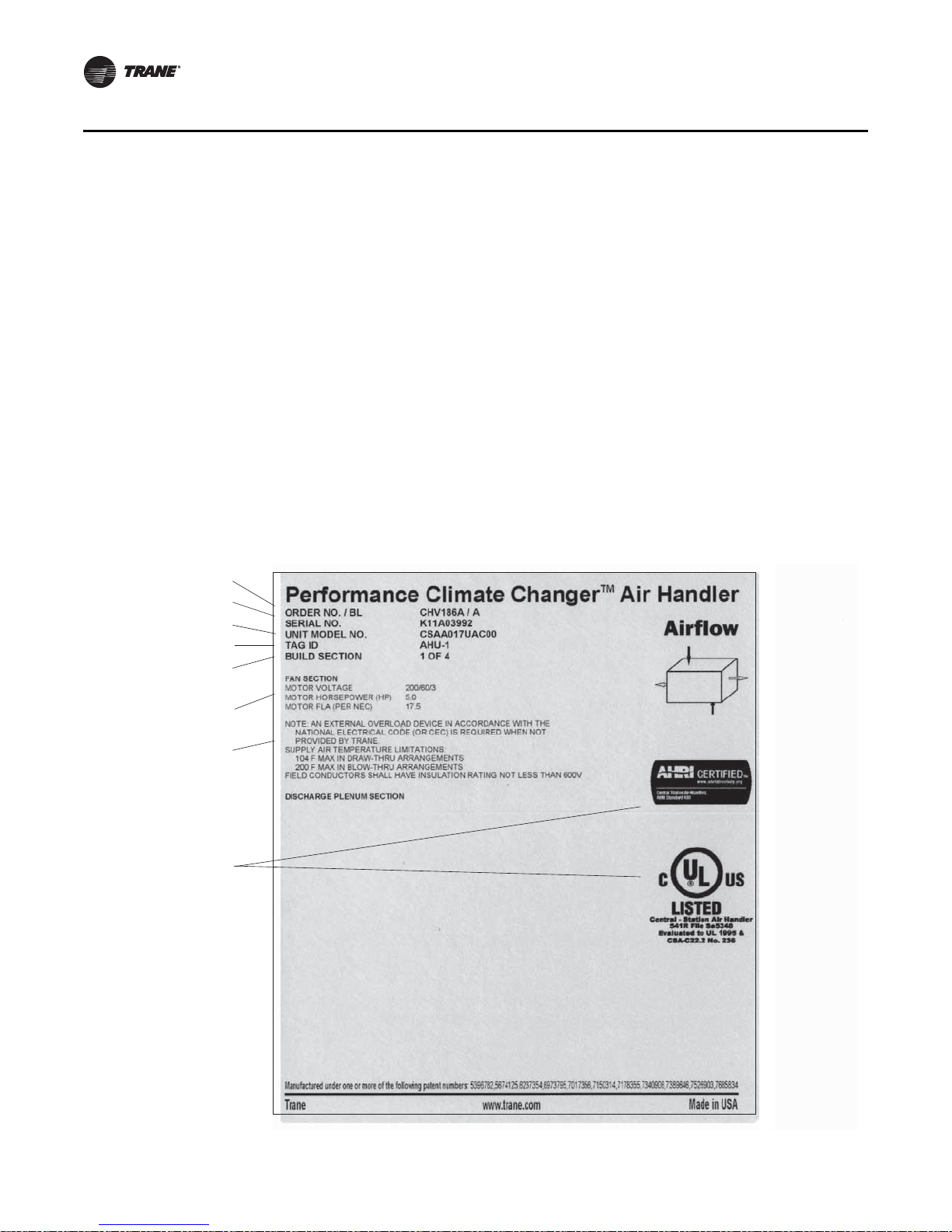
Nameplate
Each P erformance air handler section includes one or more nameplate/label (see Figure 1), which
identifies the type of section and functional components, customer tagging information, the unit
serial number, the unit order number, the build-section position for installation, and the unit model
number.
Note: The unit serial number and order number is required when ordering parts or requesting
service for a Trane air handler.
Figure 1. Performance air handler section nameplate
4 CLCH-SVX07C-EN
Page 9

Table of Contents
Introduction . . . . . . . . . . . . . . . . . . . . . . . . . . . . . . . . . . . . . . . . . . . . . . . . . . . . . . . . . . . . 4
Overview of Manual . . . . . . . . . . . . . . . . . . . . . . . . . . . . . . . . . . . . . . . . . . . . . . . . 4
Nameplate . . . . . . . . . . . . . . . . . . . . . . . . . . . . . . . . . . . . . . . . . . . . . . . . . . . . . . . . 4
General Information . . . . . . . . . . . . . . . . . . . . . . . . . . . . . . . . . . . . . . . . . . . . . . . . . . . . 9
Operating Environment . . . . . . . . . . . . . . . . . . . . . . . . . . . . . . . . . . . . . . . . . . . . . 9
Unit Description . . . . . . . . . . . . . . . . . . . . . . . . . . . . . . . . . . . . . . . . . . . . . . . . . . . 9
Pre-Installation Requirements . . . . . . . . . . . . . . . . . . . . . . . . . . . . . . . . . . . . . . . . . . 11
Receiving Checklist . . . . . . . . . . . . . . . . . . . . . . . . . . . . . . . . . . . . . . . . . . . . . . . . 11
Resolving Shipping Damage . . . . . . . . . . . . . . . . . . . . . . . . . . . . . . . . . . . . . . . 12
Storage Recommendations . . . . . . . . . . . . . . . . . . . . . . . . . . . . . . . . . . . . . . . . 12
Preparing the Unit Site . . . . . . . . . . . . . . . . . . . . . . . . . . . . . . . . . . . . . . . . . . . . 13
Roof Curb Installation Checklist . . . . . . . . . . . . . . . . . . . . . . . . . . . . . . . . . . . . . 14
Factory-Mounted Controls . . . . . . . . . . . . . . . . . . . . . . . . . . . . . . . . . . . . . . 9
Pre-Packaged Solutions for Controls . . . . . . . . . . . . . . . . . . . . . . . . . . . . . 10
Wiring . . . . . . . . . . . . . . . . . . . . . . . . . . . . . . . . . . . . . . . . . . . . . . . . . . . . . . 10
Assembly Hardware . . . . . . . . . . . . . . . . . . . . . . . . . . . . . . . . . . . . . . . . . . 12
General Storage . . . . . . . . . . . . . . . . . . . . . . . . . . . . . . . . . . . . . . . . . . . . . 13
Long-Term Storage . . . . . . . . . . . . . . . . . . . . . . . . . . . . . . . . . . . . . . . . . . . 13
Outdoor Storage Considerations . . . . . . . . . . . . . . . . . . . . . . . . . . . . . . . . 13
Unit Dimensions and Weights . . . . . . . . . . . . . . . . . . . . . . . . . . . . . . . . . . . . . . . . . . 16
Service Clearances . . . . . . . . . . . . . . . . . . . . . . . . . . . . . . . . . . . . . . . . . . . . . . . . 16
Fans/Motors . . . . . . . . . . . . . . . . . . . . . . . . . . . . . . . . . . . . . . . . . . . . . . . . . . . . . . 23
Starter/VFD Weights . . . . . . . . . . . . . . . . . . . . . . . . . . . . . . . . . . . . . . . . . . 23
Motor Weights . . . . . . . . . . . . . . . . . . . . . . . . . . . . . . . . . . . . . . . . . . . . . . . 23
Installation - Mechanical . . . . . . . . . . . . . . . . . . . . . . . . . . . . . . . . . . . . . . . . . . . . . . . 24
Lifting and Rigging . . . . . . . . . . . . . . . . . . . . . . . . . . . . . . . . . . . . . . . . . . . . . . . . 24
Remove Shipping Tie-Downs . . . . . . . . . . . . . . . . . . . . . . . . . . . . . . . . . . . 24
General Lifting Considerations . . . . . . . . . . . . . . . . . . . . . . . . . . . . . . . . . . 25
Lifting Inlet and Exhaust Hoods and External Pipe Cabinet (Chase) . . . . 27
Forklifting Considerations for Indoor Units Size 3-30 . . . . . . . . . . . . . . . 28
Unit Placement and Assembly . . . . . . . . . . . . . . . . . . . . . . . . . . . . . . . . . . . . . . 28
Unit Placement . . . . . . . . . . . . . . . . . . . . . . . . . . . . . . . . . . . . . . . . . . . . . . 29
Unit Assembly . . . . . . . . . . . . . . . . . . . . . . . . . . . . . . . . . . . . . . . . . . . . . . . 30
Ceiling Suspension for Indoor Air Handlers Sizes 3-57 . . . . . . . . . . . . . . 30
Section-to-Section Assembly . . . . . . . . . . . . . . . . . . . . . . . . . . . . . . . . . . . 32
Pipe Cabinet Installation . . . . . . . . . . . . . . . . . . . . . . . . . . . . . . . . . . . . . . . 40
Outdoor Unit Weather Hood(s) . . . . . . . . . . . . . . . . . . . . . . . . . . . . . . . . . 42
Indoor Dual-Path Split Dehumidification Unit (SDU)/Winterizer Assembly 43
Horizontal SDU/Winterizer Indoor Air Handler Assembly . . . . . . . . . . . . 44
Vertical SDU/Winterizer Indoor Air Handler Assembly . . . . . . . . . . . . . . 46
CLCH-SVX07C-EN 5
Page 10

External Raceway Assembly . . . . . . . . . . . . . . . . . . . . . . . . . . . . . . . . . . . . . . . . 48
Component Installation Requirements . . . . . . . . . . . . . . . . . . . . . . . . . . . . . . . . . . . 49
Diffuser Sections . . . . . . . . . . . . . . . . . . . . . . . . . . . . . . . . . . . . . . . . . . . . . . . . . . 49
Filter Sections . . . . . . . . . . . . . . . . . . . . . . . . . . . . . . . . . . . . . . . . . . . . . . . . . . . . 49
Filter Installation . . . . . . . . . . . . . . . . . . . . . . . . . . . . . . . . . . . . . . . . . . . . . 50
Filter Placement . . . . . . . . . . . . . . . . . . . . . . . . . . . . . . . . . . . . . . . . . . . . . . 51
Fan Sections . . . . . . . . . . . . . . . . . . . . . . . . . . . . . . . . . . . . . . . . . . . . . . . . . . . . . 61
Fan Isolation . . . . . . . . . . . . . . . . . . . . . . . . . . . . . . . . . . . . . . . . . . . . . . . . 61
Adjusting the Isolators . . . . . . . . . . . . . . . . . . . . . . . . . . . . . . . . . . . . . . . . 61
Seismic Isolation Requirements . . . . . . . . . . . . . . . . . . . . . . . . . . . . . . . . . . . . . 62
Anchor Requirements . . . . . . . . . . . . . . . . . . . . . . . . . . . . . . . . . . . . . . . . . 62
Damper Sections . . . . . . . . . . . . . . . . . . . . . . . . . . . . . . . . . . . . . . . . . . . . . . . . . 64
Damper Torque Requirements . . . . . . . . . . . . . . . . . . . . . . . . . . . . . . . . . . 64
Opposed-Blade and Parallel-Blade Dampers . . . . . . . . . . . . . . . . . . . . . . 71
Duct Connections . . . . . . . . . . . . . . . . . . . . . . . . . . . . . . . . . . . . . . . . . . . . . . . . . 71
Fan Discharge Connections . . . . . . . . . . . . . . . . . . . . . . . . . . . . . . . . . . . . 71
Damper Connections . . . . . . . . . . . . . . . . . . . . . . . . . . . . . . . . . . . . . . . . . . 72
Bottom Opening Duct Installation . . . . . . . . . . . . . . . . . . . . . . . . . . . . . . . 73
Discharge Plenum Connections . . . . . . . . . . . . . . . . . . . . . . . . . . . . . . . . . 75
Bellmouth Discharge Connections . . . . . . . . . . . . . . . . . . . . . . . . . . . . . . . 75
Traq Damper Connections . . . . . . . . . . . . . . . . . . . . . . . . . . . . . . . . . . . . . 76
External Face-and-Bypass Connections . . . . . . . . . . . . . . . . . . . . . . . . . . 76
Other Connections . . . . . . . . . . . . . . . . . . . . . . . . . . . . . . . . . . . . . . . . . . . . 78
Coil Piping and Connections . . . . . . . . . . . . . . . . . . . . . . . . . . . . . . . . . . . . . . . . . . . . 79
General Recommendations . . . . . . . . . . . . . . . . . . . . . . . . . . . . . . . . . . . . . . . . 79
Drain Pan Trapping . . . . . . . . . . . . . . . . . . . . . . . . . . . . . . . . . . . . . . . . . . . . . . . 80
Steam Coil Piping . . . . . . . . . . . . . . . . . . . . . . . . . . . . . . . . . . . . . . . . . . . . . . . . . 81
Water Coil Piping . . . . . . . . . . . . . . . . . . . . . . . . . . . . . . . . . . . . . . . . . . . . . . . . . 83
Refrigerant Coil Piping . . . . . . . . . . . . . . . . . . . . . . . . . . . . . . . . . . . . . . . . . . . . . 85
Liquid Lines . . . . . . . . . . . . . . . . . . . . . . . . . . . . . . . . . . . . . . . . . . . . . . . . . 86
Suction Lines . . . . . . . . . . . . . . . . . . . . . . . . . . . . . . . . . . . . . . . . . . . . . . . . 87
Examples of Field-Installed Evaporator Piping . . . . . . . . . . . . . . . . . . . . . . . . 89
Installation - Electrical . . . . . . . . . . . . . . . . . . . . . . . . . . . . . . . . . . . . . . . . . . . . . . . . . . 95
Quick Connects . . . . . . . . . . . . . . . . . . . . . . . . . . . . . . . . . . . . . . . . . . . . . . 99
Controls Interface . . . . . . . . . . . . . . . . . . . . . . . . . . . . . . . . . . . . . . . . . . . . . . . . . . . . . 100
Connecting the operator display . . . . . . . . . . . . . . . . . . . . . . . . . . . . . . . . . . . 100
Setting up the operator display . . . . . . . . . . . . . . . . . . . . . . . . . . . . . . . . . . . . 100
Calibrating the operator display . . . . . . . . . . . . . . . . . . . . . . . . . . . . . . . . . . . . 101
Adjusting brightness and contrast . . . . . . . . . . . . . . . . . . . . . . . . . . . . . . . . . . 101
External communications port . . . . . . . . . . . . . . . . . . . . . . . . . . . . . . . . . . . . . 101
6 CLCH-SVX07C-EN
Page 11

Start-Up . . . . . . . . . . . . . . . . . . . . . . . . . . . . . . . . . . . . . . . . . . . . . . . . . . . . . . . . . . . . . 102
Pre-Startup Checklist . . . . . . . . . . . . . . . . . . . . . . . . . . . . . . . . . . . . . . . . . . . . . 102
General Checks . . . . . . . . . . . . . . . . . . . . . . . . . . . . . . . . . . . . . . . . . . . . . . . . . . 102
Fan-Related Checks . . . . . . . . . . . . . . . . . . . . . . . . . . . . . . . . . . . . . . . . . . . . . . 103
Coil-Related Checks . . . . . . . . . . . . . . . . . . . . . . . . . . . . . . . . . . . . . . . . . . . . . . 103
Motor-Related Checks . . . . . . . . . . . . . . . . . . . . . . . . . . . . . . . . . . . . . . . . . . . . 104
Unit Operation . . . . . . . . . . . . . . . . . . . . . . . . . . . . . . . . . . . . . . . . . . . . . . . . . . . 104
Calculate Motor Voltage Imbalance . . . . . . . . . . . . . . . . . . . . . . . . . . . . . 105
Tension the Fan Belt . . . . . . . . . . . . . . . . . . . . . . . . . . . . . . . . . . . . . . . . . 106
Determine Fan Speed . . . . . . . . . . . . . . . . . . . . . . . . . . . . . . . . . . . . . . . . 107
Align Fan and Motor Sheaves . . . . . . . . . . . . . . . . . . . . . . . . . . . . . . . . . 108
Check Multiple Belts . . . . . . . . . . . . . . . . . . . . . . . . . . . . . . . . . . . . . . . . . 108
Airflow Measuring Systems . . . . . . . . . . . . . . . . . . . . . . . . . . . . . . . . . . . . . . . 109
Traq™ Dampers . . . . . . . . . . . . . . . . . . . . . . . . . . . . . . . . . . . . . . . . . . . . 109
Fan Inlet Airflow Measuring System . . . . . . . . . . . . . . . . . . . . . . . . . . . . 114
Wiring . . . . . . . . . . . . . . . . . . . . . . . . . . . . . . . . . . . . . . . . . . . . . . . . . . . . . 114
Transmitter Calibration . . . . . . . . . . . . . . . . . . . . . . . . . . . . . . . . . . . . . . . 114
Constant Factor K . . . . . . . . . . . . . . . . . . . . . . . . . . . . . . . . . . . . . . . . . . . 115
External Insulating Requirements . . . . . . . . . . . . . . . . . . . . . . . . . . . . . . . . . . 117
Troubleshooting . . . . . . . . . . . . . . . . . . . . . . . . . . . . . . . . . . . . . . . . . . . . . . . . . . . . . . 118
Routine Maintenance . . . . . . . . . . . . . . . . . . . . . . . . . . . . . . . . . . . . . . . . . . . . . . . . . 120
Maintenance Checklist . . . . . . . . . . . . . . . . . . . . . . . . . . . . . . . . . . . . . . . . . . . . 120
Air Filters . . . . . . . . . . . . . . . . . . . . . . . . . . . . . . . . . . . . . . . . . . . . . . . . . . . . . . . 121
Throwaway Filters . . . . . . . . . . . . . . . . . . . . . . . . . . . . . . . . . . . . . . . . . . . 121
Permanent Filters . . . . . . . . . . . . . . . . . . . . . . . . . . . . . . . . . . . . . . . . . . . 121
Cartridge or Bag Filters . . . . . . . . . . . . . . . . . . . . . . . . . . . . . . . . . . . . . . . 121
Drain Pans . . . . . . . . . . . . . . . . . . . . . . . . . . . . . . . . . . . . . . . . . . . . . . . . . . . . . . 121
Fans . . . . . . . . . . . . . . . . . . . . . . . . . . . . . . . . . . . . . . . . . . . . . . . . . . . . . . . . . . . . 122
Inspecting and Cleaning Fans . . . . . . . . . . . . . . . . . . . . . . . . . . . . . . . . . 122
Bearing Set Screw Alignment . . . . . . . . . . . . . . . . . . . . . . . . . . . . . . . . . 123
Fan Bearing Lubrication . . . . . . . . . . . . . . . . . . . . . . . . . . . . . . . . . . . . . . 123
Motor Bearing Lubrication . . . . . . . . . . . . . . . . . . . . . . . . . . . . . . . . . . . . 124
Fan Motor Inspection . . . . . . . . . . . . . . . . . . . . . . . . . . . . . . . . . . . . . . . . 124
Coils . . . . . . . . . . . . . . . . . . . . . . . . . . . . . . . . . . . . . . . . . . . . . . . . . . . . . . . . . . . 124
Steam and Water Coils . . . . . . . . . . . . . . . . . . . . . . . . . . . . . . . . . . . . . . . 124
Refrigerant Coils . . . . . . . . . . . . . . . . . . . . . . . . . . . . . . . . . . . . . . . . . . . . 125
Coil Winterization . . . . . . . . . . . . . . . . . . . . . . . . . . . . . . . . . . . . . . . . . . . . . . . . 126
Type D1, D2, WL, LL, UA, UW, UU, W, P2, P4, P8, WD, 5D, and 5W Coils .
127
Moisture Purge Cycle . . . . . . . . . . . . . . . . . . . . . . . . . . . . . . . . . . . . . . . . 127
Cleaning Non-Porous Surfaces . . . . . . . . . . . . . . . . . . . . . . . . . . . . . . . . 127
Cleaning Porous Surfaces . . . . . . . . . . . . . . . . . . . . . . . . . . . . . . . . . . . . . 128
CLCH-SVX07C-EN 7
Page 12

Ultraviolet (UV) Light Maintenance . . . . . . . . . . . . . . . . . . . . . . . . . . . . . . . . . 128
Cleaning the Bulbs . . . . . . . . . . . . . . . . . . . . . . . . . . . . . . . . . . . . . . . . . . 129
Replacing the Bulbs . . . . . . . . . . . . . . . . . . . . . . . . . . . . . . . . . . . . . . . . . 129
Disposal of Bulbs . . . . . . . . . . . . . . . . . . . . . . . . . . . . . . . . . . . . . . . . . . . . 130
8 CLCH-SVX07C-EN
Page 13

General Information
Operating Environment
The Performance Climate Changer™ air handler is a central station air handler for indoor
applications. When considering the placement of the air handler, it is important to consider the
operating environment. The acc ep t able ambient temperature range for unit operation is -40ºF to
140ºF (-40ºC to 60ºC).
For heating applications, a special motor may be required to withstand the higher temperatures.
Motors with Class B insulation are acceptable for ambient temperatures up to 104º F, while motors
with Class F insulation can withstand ambient temperatures to +140º F (60º C).
Note: Units with UL approval have a maximum ambient temperature requirement of 104ºF. The
customer should provide adequate freeze protectio n for the coils. See “Coil Wint erization”
on page 126 for more information.
Unit Description
The Performance Climate Changer air handler is designed for a variety of controlled-air
applications. The basic unit consists of a fan, heatin g and/or cooling coils, filters, and dampers.
T rane air handlers ship as complete assemblies or in sub-assemblies if shipping splits are required.
Some assembly is required when the unit ships in subassemblies.
A wide variety of components is available for T rane air handlers, including numerous fan, coil, and
filter options, access sections, diffusers, discharge plen ums, face-and-bypass sections, ULapproved electric heat sections, humidifiers, mixing boxes, moisture eliminator sections, exhaust
dampers, controls, blenders and airflow monitoring stations.
For more information, refer to the following documents, available from your local Trane sales
engineer:
• CLCH-PRC01 5-E N, Performance Climate Changer™air handler catalog
• CLCH-PRC01 6-EN, Performance Climate Changer™air handler quick select
• CLCH-PRG003-EN, Performance Climate Changer™air handler guide specifications
• CLCH-SLB017-EN, Performance Climate Changer™air handler sales brochure
Factory-Mounted Controls
Trane air handlers are available with a wide selection of factory-mounted controls, including
controllers, motor starters, and variable frequency drives (VFD).
Most control components are mounted inside the uni t. Depending on the system configuration,
this may include damper actuators, dirty filter switches, averaging temperature sensors, and low
limit switches. VFDs, starters, controllers, control transformers, static pressure transducers, DC
power supplies, and customer interface relays will be in enclosures mounted on the inside of the
unit.
Small items that cannot be factory-mounted, such as space temperature sensors, outside air
temperature sensors, and humidity sensors, will ship inside the control enclosures, or packaged
and shipped inside the fan or mixing box section. Larger items are shipped inside the fan section.
Note: All control valves ship directly to the “ship-to address” from the vendor unless another
address is given on the Trane sales order.
CLCH-SVX07C-EN 9
Page 14

General Information
All factory-mounted control systems (controls that are factory-wired to a unit controller or
termination strip) ordered without starters or variable-frequency drives (VFDs) are provided with
120 to 24 V ac control transformers mounted and wired in the auxiliary control panel. The customer
must provide 120 Vac control power, 50/60 Hz, typically 3 amps for unit sizes 3 to 57 and 5 amps
for unit sizes 66 to 100. A dedicated 15-amp circuit is recommended.
Factory-mounted control systems ordered with factory-mounted starters or VFDs are supplied with
line to 24 Vac control transformers. No additional power wiring is required.
Pre-Packaged Solutions for Controls
If the air handler has been selected using one of Trane’s pre-packaged solutions options for
controls, there are a number of resources available to aid in commissioning and start-up of the unit.
These resources include commissioning sheets, graphics and technical application notes. The
technical appl ication notes include the control sequencing, T rane Graphic Programming (TGP) and
Rover set-up files for the specific unit selected. These resources are available through your local
Trane sales office.
For a more in-depth understanding of controls, refer to the following manuals:
• For programmable MP580 controllers
– CNT-SVP01A-EN
• For hardware installation
– CNT-SVN01A-EN
• For Trane TR200 Drives
– BAS-SVX19A-EN
Wiring
WARNING
Proper Field Wiring and Grounding Required!
All field wiring MUST be performed by qualified personnel. Improperly installed and grounded
field wiring poses FIRE and ELECTRO CUTION hazar ds. To avoid these hazards, you MUST f ollo w
requirements for field wiring installation and grounding as described in NEC and your local/
state electrical codes. Failure to follow codes could result in death or serious injury.
Entrances are generally provided for field-installation of high and low voltage wiring through a
pipe/nipple connection in the unit depending on un it configuration with or without factorymounted controls. Before installation, consider overall unit serviceability and accessibility before
mounting, running wires (power), making penetrations, or mounting any components to the
cabinet.
Wiring to the air handler must be provided by the installer and must comply with all national and
local codes. The fan motor nameplate includes a wiring diagram. If there are any questions
concerning the wiring of the motor, write down the information on the motor nameplate and
contact your local Trane sales office.
10 CLCH-SVX07C-EN
Page 15

Pre-Installation Requirements
Based on customer requirements, Trane air handlers can ship as complete units or as individual
sections to be field assembled. Unit sizes 3-120 have an integral base frame designed with the
necessary number of lift points for safe installation. Indoor air handlers sizes 3-30 are also shipped
with a shipping skid designed for forklift transport.
Unless otherwise specified, Performance indoor air handlers ship in subassemblies if the total
length of the units exceeds 98 inches or if the total weight exceeds the limits shown in Table 1. If
either the maximum weight or maximum length is exceeded, the unit will ship in multiple pieces.
See Table 2 for limits for outdoor air handlers.
Note: These limits are based on a four-point lift.
Table 1. Shipping length and weight limitations for indoor air handlers
Unit Size Maximum Unit Weight (lb.) Maximum Unit Length (in)
3–30 <2,500 98
35 <3,900 98
40 <4,300 98
50–57 <5,100 98
66-120 <8000 98
Table 2. Shipping length and weight lim itations for outdoor air handlers
Unit Size Minimum Length (in.) Maximum Length (in.) Maximum Weight (lb.)
3–30 24.50 360.00 8,000
1
35-57
1
Notes:1Exhaust damper section can be attached to the adjacent section even if this causes length to be greater than 96
66-120
inches, up to 118.44 inches.
24.50 96.00 12,000
24.50 96.00 12,000
Receiving Checklist
Upon receipt of the air handler(s), a thorough inspection should be perfo rmed to note any shipping
damage that may have occurred and that th e shipment is complete. All factory shipping protection
should be removed immediately to allow complete access for the inspection. The shipping
protection provided by the factory is for transit protection only and should not be used as a jobsite
storage cover.
Note: Delivery cannot be refused. Trane is not responsible for shipping damage.
• Check all access doors to confirm that the latches and hinges are not damaged.
• Inspect the interior of each section for any internal damage.
Note: Concealed damage must be reported within 15 days of receipt.
• Inspect the coils for damage to the fin surface and/or coil connections.
• If the unit was ordered with factory-mounted contro ls, lo cate all sensors.
Note: Items that cannot be factory-mounted should ship inside the control enclosures or should
be packaged inside the fan or mixing box section.
• Check all control devices attached to the unit exterior and confirm that they are not damaged.
• Manually rotate the fan wheel to ensure free movement of the shaft, bearings, and drive.
• Inspect the fan housing for any foreign objects.
• If the unit is shipped in subassemblies, locate the assembly hardware, which should be
packaged and shipped inside the fan or mixing box section.
• Inspect and test all piping for possible shippi ng d amage. Nippl es m ay be i nstalled o n coi ls at
the factory but should alwa ys be tightened and tested before any connections are made. Rough
CLCH-SVX07C-EN 11
Page 16

Pre-Installation Requirements
handling during shipping, in addition to other factors can cause pipe connections to become
loose.
Note: T rane will not be responsible for any leak at the field connections. Coils have been factory
pressure tested before shipping.
Assembly Hardware
T rane air handlers ship with all necessary assembly hardware and gasket material. This hardware
is packaged in either a clear plastic envelope or cardboard box and can be found inside the fan,
mixing box, or access section. If there is not enough space inside the section, a crate or pallet will
be loaded onto the bed of the truck. Chec k the P arts List on the Field Assembly drawing against the
contents of the crate. Do not proceed with unit assembly until verification that all materials are
present. Sometimes it is necessary to use more than one section to ship hardware. Please check
all sections thoroughly before contacting your local Trane sales engineer to report missing
hardware.
Resolving Shipping Damage
T rane air handlers ship freight-on-board (FOB), meanin g that the unit belongs to the customer the
moment the delivery truck leaves the factory. If damage has occur red to the unit during shipment,
follow these instructions:
Note: Trane is not responsible for shipping da mage.
1 . Make specific notation, describing the damage, on the freight bill. Take photos of the damaged
material if possible.
2. Report all claims of shipping damage to the delivering carrier immediately and coordinate
carrier inspection if necessary.
Note: Do not attempt to repair the unit without consulting the delivering carrier.
3. Notify your Trane sales representative of the damage and arrange for repair.
Note: Do not attempt to repair the unit without consulting the Trane sales representative.
4. Keep the damaged material in the same location as it was received.
Note: It is the receiver's responsibility to provide reasonable evidence that concealed damage was
not incurred after delivery.
Storage Recommendations
NOTICE:
Corrosion!
All factory shipping protection should be removed. This wrapping is for transit protection only
and should not be used for jobsite storage.Use only canvas tarps to cover air handlers. Plastic
tarps can cause condensation to form in and on the equipment, which could result in corrosion
damage or wet storage stains.
Indoor air handlers and/or field-installed accessories that must be stored for a period of time before
installation must be protected from the elements. A controlled indoor environment is
recommended for proper storage.
Outdoor air handlers require no specia l protection for storage before installation. Keep the
equipment in the original container for protection and ease of handling.
Note: The warranty does not cover damage to the unit or controls due to negligence during
storage.
12 CLCH-SVX07C-EN
Page 17

General Storage
The unit controller and all other electrical/electroni c components should be stored in conditions of
-20ºF to 120°F and 5 to 95 percent relative humidity, non-condensing. Electrical components are
not moisture-tolerant. Factory protective coverings should be removed prior to storage.
Long-Term Storage
For longer periods of storage, allow proper clearance around the unit to perform periodic
inspection and maintenance of the equipment.
While the unit is in storage:
• Every two weeks, rotate the fan and motor shaft 30 revolutions by hand. Chec k for free rotation.
• Every six months, chec k fan shaft bearings and grease lines. Add grease using a manual grease
gun following the lubrications recommendations in “Fan Bearing Lubrication” on page 123.
• Check the motor lubrication; remove and clean grease plugs and check for the presence of
moisture in the grease. If moisture is present, remove the motor and send it to an authorized
repair shop for bearing inspection/replacement. If no moisture if present, refer to the motor
manufacturer’s lubrication reco mm end ati on for proper lu bricatio n.
Outdoor Storage Considerations
Outdoor storage is not recommended for units that will be installed indoors. However, when
outdoor storage is necessary, several things must be done to prevent damage :
Note: Keep the equipment on the o riginal wooden blocks/skid fo r protection and ease of handling.
• Select a well-drained area, preferably a concrete pad or blacktop surface.
• Place the unit on a dry surface or raised off the ground to assure adequate air circulation
beneath the unit and to assure no portion of the unit will contact standing water at any time.
• Loosen the belt tension on the drive belts.
• Cover the unit securely with a canvas tarp.
• Do not stack units.
• Do not pile other material on the unit.
Pre-Installation Requirements
Preparing the Unit Site
• Ensure the installation site can support the total weight of the unit (see “Unit Dimensions and
Weights” on page 16 for approximate section weights; refer to the unit submittals for actual
weights).
• Allow sufficient space for adequate free air and necessary service access (see “Service
Clearances” on page 16). Refer to submittals for specific minimums.
• Allow room for supply and return piping, ductwork, electrical connections, and coil removal.
• Ensure there is adequate height for condensate drain requirements. See “Drain Pan T rappi ng”
on page 80.
Note: If unit is installed in a mechanical room on a pad, inadequate height may necessitate core-
drilling the floor to attain proper trap height. Insufficient height could inhibit condensate
drainage and result in flooding the unit and/or equipment room.
CLCH-SVX07C-EN 13
Page 18

Pre-Installation Requirements
NOTICE:
Microbial Growth!
The floor or foundation must be level and the condensate drain at the proper heig ht for proper
coil drainage and condensate flow. Standing water and wet surfaces inside the equipment can
become an amplification site for microbial growth (mold), which may cause odors and damage
to the equipment and building materials.
• Confirm the roof curb or foundation of the mounting platform is level and large enough to
accommodate the unit. Refer to the unit submittals for specific dimensions.
• Provide adequate lighting for maintenance personnel to perform maintenance duties.
• Provide permanent power outlets in close proximity to the unit for installation and
maintenance.
• Depending upon job requirements, the customer may n eed to provide 120 V ac power to the unit
controller. Refer to submittals for more information. A dedicated 15-amp circuit is
recommended.
• Wiring for the air handler must be provided by the installer and must com ply with all national
and local electrical codes.
• If the unit integral base frame ceiling suspension provisions are not used, the installer/
contractor must provide a ceiling-susp ended mounting frame desig ned to support the length,
width, and weight of the entire air-handling unit. See “Ceiling Suspension for Indoor Air
Handlers Sizes 3-57” on page 30 for more information.
• Rooftop curb-mount ed units m ust be sealed tightly to the curb. Use proper sealants and roofto-curb sealing techniques to prevent water and air leakage. Refer to CLCH-SVN05A-EN Roof
Curbs for Performance Climate Changer™ Air Handlers Installation Instructions.
Note: Preparation of the roof curb or pier mount and roof openings should be completed prior to
lifting the unit to the roof.
Roof Curb Installation Checklist
See CLCH-SVN05A-EN Roof Curbs for Performance Climate Changer™ Air Handlers Installation
Instructions for information on installing roof curbs.
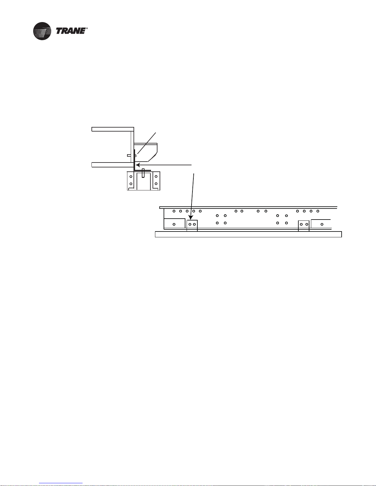
It is recommended that the curb be installed directly on the support members and fastened to the
supports using tack welds or other equivalent methods. Properly supported decking should be
installed inside the air handler section of the curb when this method is used. See Figure 2.
14 CLCH-SVX07C-EN
Page 19
Pre-Installation Requirements
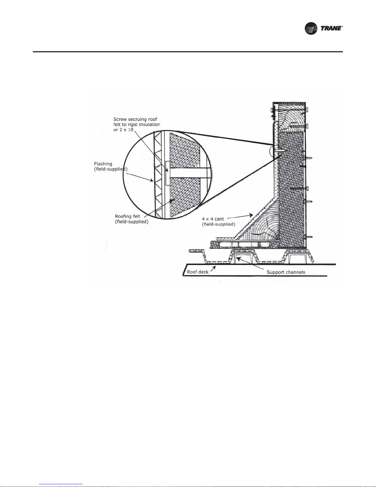
Figure 2. Cross section of typical curb installation on new construction
1 . Verify that the roof structure can adequately support the combined weight of the unit and curb
assembly.
2. Ensure that the selected installation location provides sufficient service and operational
clearances.
3. Remove any twist within the curb due to roof supports and square the curb.
4. Level the curb.
5. Secure the curb to the roof support members.
6. Install 2-inch thick boards or rigid insulation around the curb.
7. Install cant strips around the curb.
8. Bring field supplied roofing felt up to the top of the curb nailing strips. Nail felt into place.
9. Install field supplied flashing under the lip of the curb flanges and over the felt.
Apply sealant to the four corners. Caulk all joints between the curb and the roof. Attach the g asket
material to the curb’ s top flanges (entire perimeter) and to the supply and return air duct opening
panel flanges.
CLCH-SVX07C-EN 15
Page 20
Unit Dimensions and Weights
Filter mixing box
Coil
Fan
Gas heat
Access
door
UV
lights
VFD
F
E
D
C
B
A
Note: For specific dimensional and weight information, refer to the unit submittals. The
dimensions and weights in this manual are approximate. T rane has a p olicy of continuous
product and product data improvement and reserves the right to change design and
specifications without notice.
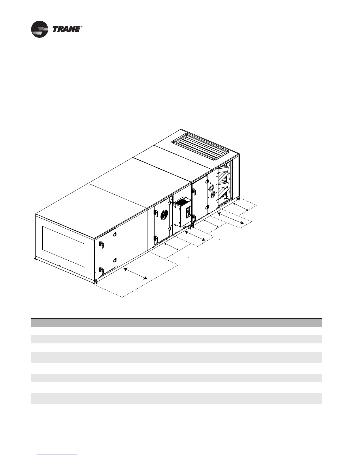
Service Clearances
Figure 3. Service Clearance
Table 3. Service clearances (inches)
Component 3 4 6 8 10 12 14 17 21 25 30 35 40 50 57 66 80 100 120
A (filter)
B (coil)
C (UV Lights)
D (external
starter or VFD)
D (internal
starter or VFD)
E (fan)
F (gas heat Ext Vestibule)
F (gas heat Int Vestibule)
Note: At a minimum, the above clearance dimensions are recommended on one side of the unit for regular service and maintenance. Refer to as-built
submittal for locations of items such as filter access doors, coil, piping connections, motor locations, hoods, pipe cabinets, etc. Sufficient clearance
must be provided on all sides of unit for removal of access panels, plug panels, or section-to-section attachment brackets. Clearance for starters, VFDs,
or other high-voltage devices must be provided per NEC requi rements.
16 CLCH-SVX07C-EN
48 48 48 48 48 48 48 48 48 48 48 48 48 48 48 52 56 58 58
48 59 59 66 77 82 87 87 95 95 109 115 128 141 141 156 156 170 197
48 48 48 48 48 48 48 48 48 48 48 48 48 48 48 52 56 58 58
61 61 61 61 61 61 61 61 64 64 64 64 64 64 64 64 64 64 64
48 48 48 48 48 48 48 48 48 48 48 48 48 48 48 48 48 48 48
48 48 48 48 51 54 58 61 60 66 66 66 70 77 77 93 93 101 101
N/A N/A 89 90 108 100 100 105 115 115 118 136 140 156 156 170 179 180 N/A
N/A N/A 56 63 74 79 84 84 92 92 106 112 125 138 138 153 153 167 194
Page 21
Unit Dimensions and Weights
Note: Add 0.19 inches to total unit length for each shipping split to account for gasketing.
Table 4. Section dimensions (inches) and weigh ts (po unds) - unit sizes 3-30
Nominal airflow
Airflow at 625 fpm
1
2
Unit size 3 4 6 8 10 12 14 17 21 25 30
Height - indoor unit (in.)
3
Height - outdoor unit (in.)4
includes base drip lip
Width (in.)
Weight add for outdoor unit
(lbs/in. of unit length)
Mixing box
-with or without angled filters
-with top Traq dampers
-with reduced length for airfoil
dampers only
Filters
-2-in. or 4-in. angled
-Cartridge 12-in. or
short bag 18-in.
-2-in. or 4-in. flat
-2-in. and 4-in. combination flat
-Long bag 30-in.
-Front-load
2-in or 4-in.flat, cartridge or HEPA
-Front-load Short Bag
Access or blank
-Small horizontal
-Medium horizontal
-Extended-medium horizontal
-Medium-large horizontal
-Large horizontal or turning
-Extra-large horizontal or turning
Note:1Nominal airflow is based on 500 fpm through a nominal coil (i.e. 500xunit size 8=4000 cfm). 2Airflow@625 fpm through the flat filter (maximum
filter velocity).
frame for sizes 3-120.
7
Nominal length and height shown for discharge plenums. Variable plenum height and length is available from 0.5 to 1.5 of nominal.
5
3
Height includes standard 2.5-inch base frame for sizes 3-57 and 6-inch base frame for sizes 66-120. 4Height includes 6-inch base
5
Variable lengths av ailable from 14-96 inches. 6Fan section weights include the heaviest fan with the largest ODP motor available.
1500 2,000 3000 4000 5000 6000 7000 8500 10,500 12,500 15,000
2169 3475 4338 4581 6075 8331 9025 11,806 13,456 16,944 19,025
29.00 29.00 35.25 37.75 37.75 41.50 41.50 49.00 52.75 61.50 61.50
37.30 37.45 43.70 46.20 46.20 50.33 50.33 57.83 61.58 70.33 70.33
31.50 44.00 44.00 50.50 61.50 66.50 72.00 72.00 80.00 80.00 93.50
1.66 1.91 1.91 2.04 2.27 2.40 2.51 2.51 2.67 2.67 2.95
34.00 34.00 34.00 36.00 36.00 36.00 36.00 36.00 34.00 46.00 46.00
192.59 219.00 237.28 277.86 313.45 346.29 365.78 391.36 423.13 539.50 595.82
36.00 41.00 41.00 44.00 42.50 42.50 42.50 44.00 50.25 56.50 56.50
199.73 245.85 265.79 313.60 345.77 381.04 402.17 438.43 527.04 610.12 672.97
23.38 23.38 23.38 23.38 23.38 23.38 28.38 28.38 28.38 28.38 32.50
132.81 150.12 164.65 185.54 210.93 231.01 273.01 293.45 326.35 352.21 424.41
24.50 24.50 24.50 26.50 26.50 26.50 26.50 24.50 24.50 24.50 24.50
129.35 155.03 166.86 192.04 215.56 236.22 250.34 286.12 316.30 356.90 398.99
24.50 24.50 24.50 26.50 26.50 26.50 26.50 24.50 24.50 24.50 24.50
101.83 121.39 130.06 152.86 171.58 192.72 204.20 203.82 222.30 249.79 275.06
14.00 14.00 14.00 14.00 14.00 14.00 14.00 14.00 14.00 14.00 14.00
68.56 82.62 88.08 99.49 111.80 124.66 131.47 136.82 152.24 164.95 183.13
19.00 19.00 19.00 19.00 19.00 19.00 19.00 19.00 19.00 19.00 19.00
86.42 103.79 110.69 124.26 139.53 161.09 171.37 179.37 198.37 224.08 247.88
36.00 41.00 41.00 44.00 42.50 42.50 42.50 44.00 50.25 46.00 46.00
133.38 174.65 187.12 219.08 237.62 268.97 283.79 306.36 369.18 379.56 415.84
40.00 40.00 40.00 40.00 40.00 40.00 40.00 40.00 40.00 40.00 40.00
198.25 220.89 244.19 268.72 292.11 320.14 333.11 370.55 401.66 433.13 470.67
45.00 45.00 45.00 45.00 45.00 45.00 45.00 45.00 45.00 45.00 45.00
218.15 242.55 268.05 294.69 320.16 350.45 364.47 404.55 438.50 473.05 513.15
10.00 10.00 10.00 10.00 10.00 10.00 10.00 10.00 10.00 10.00 10.00
48.05 57.43 60.55 66.67 74.92 80.55 84.67 88.41 96.28 100.65 110.78
14.00 14.00 14.00 14.00 14.00 14.00 14.00 14.00 14.00 14.00 14.00
59.91 71.18 75.25 82.74 92.66 99.61 104.57 109.45 119.10 124.79 136.97
19.00 19.00 19.00 19.00 19.00 19.00 19.00 19.00 19.00 19.00 19.00
74.73 88.37 93.62 102.82 114.83 123.43 129.44 135.74 147.62 154.97 169.71
24.50 24.50 24.50 26.50 26.50 26.50 26.50 24.50 24.50 24.50 24.50
111.30 124.41 131.71 154.47 173.94 187.69 197.48 195.61 214.03 225.11 248.63
34.00 34.00 34.00 36.00 36.00 36.00 36.00 36.00 34.00 46.00 46.00
145.22 160.85 170.40 196.91 221.19 238.48 250.67 263.28 274.77 369.72 406.60
36.00 41.00 41.00 44.00 42.50 42.50 42.50 44.00 50.25 56.50 56.50
152.36 187.71 198.92 232.65 253.52 273.22 287.07 310.34 378.68 369.72 406.60
CLCH-SVX07C-EN 17
Page 22
Unit Dimensions and Weights
Table 4. Section dimensions (inches) and weigh ts (po unds) - unit sizes 3-30
Unit size 3 4 6 8 10 12 14 17 21 25 30
Coil
-Small horizontal (with 4-row UW)
-Medium horizontal (with 8-row UW)
-Extended-medium horizontal
(with 8-row UW)
-Medium-large horizontal
(with 10-row W)
-Large horizontal or vertical
(with 10-row W)
6
Fan
-Belt-drive plenum fan with motor
-Housed fan (FC/AF/BC) with motor
-Direct-drive plenum fan with motor
Controls section (includes largest
available VFD)
Diffuser
Discharge plenum
-Horizontal
-Vertical
Blender
Electric Heat
7
Face-and-Bypass Dampers
-Internal face-and-bypass or
face damper only
-External face-and-bypass
Energy Wheel
CDQ Wheel
Integral-face-and-bypass coil
-Less than 4 rows
-4 rows
10.00 10.00 10.00 10.00 10.00 10.00 10.00 10.00 10.00 10.00 10.00
127.31 164.68 191.68 226.20 269.31 310.76 335.50 384.32 467.78 533.75 609.14
14.00 14.00 14.00 14.00 14.00 14.00 14.00 14.00 14.00 14.00 14.00
179.86 236.36 282.91 339.38 407.35 475.70 516.37 601.64 734.68 848.92 978.12
19.00 19.00 19.00 19.00 19.00 19.00 19.00 19.00 19.00 19.00 19.00
196.79 255.65 303.39 361.57 431.62 501.63 544.40 631.09 772.37 889.31 1021.94
24.50 24.50 24.50 26.50 26.50 26.50 26.50 26.50 26.50 26.50 26.50
281.83 375.92 450.41 575.29 681.45 802.89 912.98 1045.42 1296.51 1509.94 1738.41
34.00 34.00 34.00 36.00 36.00 36.00 36.00 36.00 34.00 46.00 46.00
313.98 412.58 489.32 617.44 727.56 852.16 966.23 1113.15 1368.11 1683.65 1926.83
36.00 41.00 41.00 44.00 42.50 42.50 42.50 44.00 50.25 56.50 56.50
406.54 537.13 625.09 674.57 864.70 936.46 1052.78 1214.74 1414.95 1495.75 1736.99
36.00 41.00 41.00 44.00 42.50 42.50 42.50 44.00 50.25 56.50 56.50
387.54 466.14 568.41 641.41 839.41 904.62 925.53 1073.07 1403.49 1535.79 1755.04
36.00 41.00 41.00 44.00 46.75 48.50 48.50 50.00 50.25 50.25 52.50
335.20 450.11 446.52 576.33 663.63 746.10 767.31 799.69 1095.84 1182.66 1263.84
24.50 24.50 24.50 24.50 24.50 24.50 24.50 24.50 24.50 24.50 24.50
234.30 247.41 276.71 299.47 318.94 332.69 414.48 423.00 442.03 463.11 486.63
10.00 10.00 10.00 14.00 14.00 14.00 14.00 14.00 14.00 19.00 19.00
53.76 63.14 68.53 90.94 100.86 116.94 121.90 129.34 143.02 185.04 199.78
34.00 34.00 34.00 36.00 36.00 36.00 36.00 36.00 34.00 46.00 46.00
150.01 185.36 196.57 230.30 251.17 270.87 284.72 307.99 376.33 367.37 404.25
36.00 41.00 41.00 44.00 42.50 42.50 42.50 44.00 50.25 56.50 56.50
177.24 209.05 221.00 259.71 285.68 308.68 325.46 351.14 429.14 497.02 549.91
19.00 24.50 24.50 26.50 36.00 36.00 36.00 36.00 34.00 46.00 46.00
94.86 132.71 146.30 173.34 238.64 264.12 276.73 303.71 323.59 427.13 470.25
36.00 41.00 41.00 44.00 42.50 42.50 42.50 44.00 50.25 56.50 56.50
261.39 309.88 335.38 449.00 471.92 500.13 513.26 627.76 705.10 857.44 898.23
19.00 19.00 19.00 19.00 19.00 19.00 19.00 19.00 19.00 19.00 19.00
122.68 155.15 167.79 190.70 219.68 241.45 255.80 270.77 300.08 317.53 353.22
19.00 19.00 19.00 19.00 19.00 19.00 19.00 19.00 19.00 19.00 19.00
105.60 129.06 141.70 157.63 178.68 199.15 209.53 224.50 248.05 265.62 291.36
n/a 52.25 52.25 52.25 54.50 57.50 57.50 57.50 55.50 55.50 57.50
n/a 364.17 378.70 457.21 561.31 676.15 766.30 786.59 879.93 917.84 1135.01
52.25 52.25 52.25 52.25 54.50 57.50 57.50 57.50 55.50 55.50 57.50
284.39 406.17 420.70 484.21 661.31 756.15 884.30 905.99 1189.41 1213.44 1310.61
n/a 26.50 26.50 26.50 26.50 26.50 26.50 26.50 26.50 26.50 26.50
n/a 355.20 367.21 470.21 541.93 585.86 619.66 733.14 792.88 805.52 940.46
n/a 43.00 43.00 43.00 43.00 43.00 43.00 4 3.00 43.00 43.00 43.00
n/a 543.54 559.47 723.32 834.36 900.62 950.23 1130.33 1220.11 1403.29 1443.62
18 CLCH-SVX07C-EN
Page 23
Unit Dimensions and Weights
Table 4. Section dimensions (inches) and weigh ts (po unds) - unit sizes 3-30
Unit size 3 4 6 8 10 12 14 17 21 25 30
Humidifier
-Direct Steam
-Atmospheric
Silencer
-3 ft
-5 ft
2-deck or 3-deck Multizone
- Horizontal discharge
- Vertical discharge
UV light
Gas heat (highest MBH) n/a n/a
Horizontal end cap
Diagonal economizer for
outdoor unit
Exhaust damper section for
outdoor unit
Hoods
- Side inlet hood (add to width) for
diagonal economizer
- Side inlet hood (add to width) for
mixing box
- Back inlet hood (add to length) for
mixing box
- Exhaust hood (add to length or
width)
Pipe cabinet weight
15 inches long, 36 inches deep 104.00 104.00 116.00 120.00 120.00 127.00 127.00 141.00 148.00 164.00 164.00
24 inches long, 36 inches deep 122.00 122.00 135.00 140.00 140.00 147.00 147.00 162.00 170.00 187.00 187.00
48 inches long, 36 inches deep 169.00 169.00 184.00 191.00 191.00 200.00 200.00 218.00 228.00 249.00 249.00
96 inches long, 36 inches deep 263.00 263.00 284.00 293.00 293.00 305.00 305.00 331.00 343.00 373.00 373.00
14.00 14.00 14.00 14.00 14.00 14.00 14.00 14.00 14.00 14.00 14.00
125.26 145.84 165.02 183.76 225.95 268.70 285.76 323.51 354.22 397.93 452.06
14.00 14.00 14.00 14.00 14.00 14.00 14.00 14.00 14.00 14.00 19.00
126.77 167.88 177.85 203.32 252.08 276.18 311.72 338.64 396.01 432.20 527.53
38.00 38.00 38.00 38.00 38.00 38.00 38.00 38.00 38.00 38.00 38.00
198.00 255.81 285.56 319.00 358.76 442.35 461.27 511.98 573.44 699.10 799.58
62.00 62.00 62.00 62.00 62.00 62.00 62.00 62.00 62.00 62.00 62.00
308.14 391.33 435.77 483.40 541.16 677.72 703.65 780.18 873.34 1072.96 1214.72
n/a n/a 52.00 52.00 52.00 57.00 57.00 57.00 72.00 72.00 72.00
n/a n/a 521.86 581.76 672.98 751.82 795.28 829.01 1074.90 1130.69 1260.57
n/a n/a 61.00 61.00 66.00 71.00 71.00 71.00 82.00 82.00 82.00
n/a n/a 615.93 676.27 832.69 922.38 966.31 1005.77 1228.90 1292.74 1418.36
14.00 14.00 14.00 14.00 14.00 14.00 14.00 14.00 14.00 14.00 14.00
76.02 93.64 98.69 120.26 135.22 146.68 155.07 162.95 179.84 188.71 218.33
69.00 69.00 67.00 65.00 64.00 73.00 76.00 76.00 75.00
884.80 934.90 1042.60 1070.00 1089.00 1420.50 1294.80 1394.50 1477.70
10.0 10.0 10.0 10.0 10.0 10.0 10.0 10.0 10.0 10.0 10.0
59.5 68.8 72.7 80.8 91.9 99.5 105.1 110.3 121.3 127.6 142.1
45.50 49.00 49.50 48.00 53.00 53.00 56.50 52.00 62.50 57.00 62.50
203.89 247.13 270.83 289.91 348.65 378.29 425.94 431.12 554.51 565.16 689.49
19.00 19.00 19.00 19.00 19.00 19.00 19.00 19.00 19.00 19.00 19.00
91.70 103.30 109.30 121.00 136.07 147.60 155.50 163.30 178.90 188.10 208.20
16.63 17.88 17.38 22.25 17.38 19.38 19.38 21.38 22.63 25.63 27.75
22.11 44.51 46.71 72.36 51.90 69.11 74.11 87.31 105.51 128.29 165.87
15.38 15.38 17.50 19.75 19.75 23.00 21.13 24.75 27.75 32.13 35.25
17.38 17.38 22.37 28.48 31.07 41.83 50.11 51.75 69.06 83.64 95.67
16.63 17.88 17.38 22.25 17.38 19.38 19.38 21.38 22.63 25.63 27.75
22.11 44.51 46.71 72.36 51.90 69.11 74.11 87.31 105.51 128.29 165.87
15.38 15.38 17.50 19.75 19.75 23.00 21.13 24.75 27.75 32.13 35.25
12.36 12.36 15.95 20.47 21.26 29.08 29.65 34.70 45.03 58.67 67.02
CLCH-SVX07C-EN 19
Page 24
Unit Dimensions and Weights
Notes: Add 0.19 inches to total unit length for each shipping split to account for gasketing.
Table 5. Section dimensions (inches) and wei gh ts (poun ds) - unit sizes 35-120
Nominal airflow
Airflow at 625 fpm
1
2
Unit size 35 40 50 57 66 80 100 120
Height - indoor unit (in.)
3
Height - outdoor unit (in.)4
includes base drip lip
Width (in.)
Weight add for outdoor unit
(lbs/in. of unit length)
Mixing box
-with or without angled filters
-with top Traq dampers
-with reduced length for airfoil
dampers only
Filters
-2-in. or 4-in. angled
-Cartridge (12-in.) or
short bag (18-in.)
-2-in. or 4-in. flat
-2-in. and 4-in. combination flat
-Long bag (30-in.)
-Front-load
2-in or 4-in.flat, cartridge or HEPA
-Front-load Short Bag
Access or blank
-Small horizontal
-Medium horizontal
-Extended-medium horizontal
-Medium-large horizontal
-Large horizontal or turning
-Extra-large horizontal or turning
Note:1Nominal airflow is based on 500 fpm through a nominal coil (i.e. 500xunit size 8=4000 cfm). 2Airflow@625 fpm through the flat filter (maximum
filter velocity).
frame for sizes 3-120.
7
Nominal length and height shown for discharge plenums. Variable plenum height and length is available from 0.5 to 1.5 of nominal.
5
3
Height includes standard 2.5-inch base frame for sizes 3-57 and 6-inch base frame for sizes 66-120. 4Height includes 6-inch base
5
Variable lengths av ailable from 14-96 inches. 6Fan section weights include the heaviest fan with the largest ODP motor available.
17,500 20,000 25,000 28,500 33,000 40,000 50,000 60,000
23,263 25,519 34,375 39,581 47,225 53,475 65,106 76,388
67.25 67.25 75.75 85.50 92.50 107.50 119.75 119.75
76.075 76.075 85.45 95.20 102.20 117.20 129.45 129.45
100.00 112.50 125.50 125.50 140.50 140.50 154.50 182.00
3.02 3.28 3.74 6.13 2.88 2.88 3.11 3.55
48.00 48.00 48.00 48.00 49.00 54.00 60.00 60.00
784.64 877.19 980.34 1055.78 1344.75 1501.00 1772.41 2016.97
48.00 48.00 48.00 48.00 84.00 92.00 96.00 96.00
917.88 1019.49 1188.45 1271.47 1812.46 2030.42 2313.89 2604.03
35.50 38.50 41.50 41.50 41.50 41.50 47.00 53.00
635.84 716.69 845.71 845.71 1183.44 1272.94 1508.57 1773.61
24.50 24.50 27.50 27.50 27.50 27.50 27.50 27.50
533.86 580.66 676.42 704.29 882.20 945.62 1032.36 1136.60
24.50 24.50 27.50 27.50 27.50 27.50 27.50 27.50
428.04 438.45 549.07 566.64 775.99 807.31 927.71 1031.64
14.00 14.00 14.00 14.00 15.00 15.00 15.00 15.00
294.60 319.13 353.93 379.91 533.87 560.15 623.46 699.50
19.00 19.00 19.00 19.00 19.00 19.00 19.00 19.00
397.10 430.77 482.70 540.44 700.68 779.12 862.09 908.32
37.25 37.25 37.25 37.25 37.25 37.25 37.25 37.25
525.02 570.65 637.71 692.97 894.76 971.09 1061.74 1125.66
40.00 40.00 40.00 40.00 40.00 40.00 40.00 40.00
636.18 676.08 763.56 806.39 1031.28 1121.46 1250.59 1368.55
45.00 45.00 45.00 45.00 45.00 45.00 45.00 45.00
684.89 727.15 821.08 867.34 1106.39 1201.85 1337.95 1461.13
10.00 10.00 10.00 10.00 n/a n/a n/a n/a
211.11 227.92 254.69 265.35 n/a n/a n/a n/a
14.00 14.00 14.00 14.00 15.00 15.00 15.00 15.00
241.53 260.24 290.28 302.41 430.36 449.60 493.59 549.13
19.00 19.00 19.00 19.00 19.00 19.00 19.00 19.00
279.57 300.64 334.76 348.74 476.36 497.88 545.85 605.56
24.50 24.50 24.50 24.50 24.50 24.50 24.50 24.50
267.55 289.53 324.20 337.75 475.62 497.08 547.88 613.24
48.00 48.00 48.00 48.00 49.00 54.00 60.00 60.00
452.37 487.88 544.19 566.43 771.76 870.43 1036.54 1146.85
63.75 63.75 68.50 n/a n/a n/a n/a n/a
367.83 397.14 443.56 n/a n/a n/a n/a n/a
20 CLCH-SVX07C-EN
Page 25
Unit Dimensions and Weights
Table 5. Section dimensions (inches) and wei gh ts (poun ds) - unit sizes 35-120
Unit size 35 40 50 57 66 80 100 120
Coils
-Small horizontal (with 4-row UW)
-Medium horizontal (with 8-row UW)
-Extended-medium horizontal
(with 8-row UW)
-Medium-large horizontal
(with 10-row W)
-Large horizontal or vertical
(with 10-row W)
6
Fan
-Belt-drive plenum fan with motor
-Housed fan (FC/AF/BC) with motor
-Direct-drive plenum fan with motor
Controls section (includes largest
available VFD)
Diffuser
Discharge plenum
-Horizontal
-Vertical
Blender
Electric Heat
7
Face-and-Bypass Dampers
-Internal face-and-bypass or
face damper only
-External face-and-bypass
Energy Wheel
CDQ Wheel
Integral-face-and-bypass coil
-Less than 4 rows
-4 rows
10.00 10.00 10.00 10.00 n/a n/a n/a n/a
679.61 743.10 915.56 1023.99 n/a n/a n/a n/a
14.00 14.00 14.00 14.00 15.00 15.00 15.00 15.00
1083.29 1208.28 1543.21 1739.24 2183.23 2518.10 3045.45 3584.41
19.00 19.00 19.00 19.00 19.00 19.00 19.00 19.00
1137.72 1267.13 1595.08 1793.51 2237.43 2574.51 3116.83 3660.64
24.50 24.50 24.50 24.50 24.50 24.50 24.50 24.50
1944.10 2204.75 2736.01 3195.47 3838.02 4447.61 5453.04 6662.13
48.00 48.00 48.00 48.00 n/a n/a n/a n/a
2140.10 2411.83 2991.25 3459.40 n/a n/a n/a n/a
53.50 53.50 57.50 59.50 61.00 63.00 73.75 82.25
2311.19 2676.28 3178.70 3496.17 3940.63 4590.36 6035.46 7133.78
63.75 63.75 68.50 68.50 84.00 92.00 96.00 96.00
2381.09 2641.30 3148.10 3211.05 4216.56 4980.29 5866.21 6705.45
55.50 60.00 65.00 65.00 54.75 54.75 54.75 54.75
1648.42 1910.99 2793.74 2851.21 3433.31 3950.32 5356.05 5525.47
24.50 24.50 24.50 24.50 24.50 24.50 24.50 24.50
574.55 596.53 631.20 644.75 782.62 804.08 854.88 920.24
24.50 24.50 24.50 24.50 27.50 37.25 37.25 37.25
365.56 389.25 428.01 445.57 664.01 809.34 876.54 955.28
48.00 48.00 48.00 48.00 49.00 54.00 60.00 60.00
474.26 511.01 570.20 594.26 773.17 810.80 891.34 989.20
63.75 63.75 68.50 n/a n/a n/a n/a n/a
779.25 840.96 989.88 n/a n/a n/a n/a n/a
48.00 48.00 48.00 48.00 49.00 54.00 60.00 60.00
540.76 593.46 675.51 731.75 970.30 1112.23 1345.03 1567.62
n/a n/a n/a n/a n/a n/a n/a n/a
n/a n/a n/a n/a n/a n/a n/a n/a
19.00 19.00 19.00 19.00 19.00 19.00 19.00 19.00
543.64 636.11 713.60 803.86 1026.07 1107.46 1236.82 1361.55
22.00 22.00 22.00 22.00 39.00 39.00 39.00 39.00
473.39 556.23 630.10 714.61 888.33 973.60 1093.88 1205.53
61.25 64.75 64.75 n/a n/a n/a n/a n/a
1497.92 1733.76 1995.01 n/a n/a n/a n/a n/a
56.25 56.25 58.75 n/a n/a n/a n/a n/a
2127.92 2323.76 3275.01 n/a n/a n/a n/a n/a
29.50 29.50 29.50 29.50 29.50 29.50 29.50 29.50
1129.66 1168.40 1793.80 1956.80 2322.61 2378.60 2865.77 2936.42
43.00 43.00 n/a n/a n/a n/a n/a n/a
1681.45 1726.58 n/a n/a n/a n/a n/a n/a
CLCH-SVX07C-EN 21
Page 26
Unit Dimensions and Weights
Table 5. Section dimensions (inches) and wei gh ts (poun ds) - unit sizes 35-120
Unit size 35 40 50 57 66 80 100 120
Humidifier
-Direct steam
-Atmospheric
Silencer
-3 ft
-5 ft
2-Deck or 3-Deck Multizone
- Horizontal discharge
- Vertical discharge
UV light
Gas heat (highest MBH)
Horizontal end cap
Diagonal economizer for
outdoor unit
Exhaust damper section for
outdoor unit
Hoods
- Side inlet hood (add to width) for
diagonal economizer
- Side inlet hood (add to width) for
mixing box
- Back inlet hood (add to length) for
mixing box
- Exhaust hood (add to length or
width)
Pipe cabinet weight
15 inches long, 36 inches deep 175.00 175.00 191.00 209.00 215.00 243.00 265.00 265.00
24 inches long, 36 inches deep 199.00 199.00 216.00 236.00 243.00 273.00 298.00 298.00
48 inches long, 36 inches deep 263.00 263.00 284.00 309.00 317.00 354.00 385.00 385.00
96 inches long, 36 inches deep 392.00 392.00 421.00 454.00 466.00 517.00 558.00 558.00
14.00 14.00 14.00 14.00 15.00 15.00 15.00 15.00
544.40 599.28 781.71 897.00 1123.05 1215.33 1362.86 1551.07
19.00 19.00 19.00 19.00 19.00 19.00 19.00 19.00
581.42 664.92 723.70 802.82 977.24 1078.41 1264.58 1491.95
38.00 38.00 38.00 38.00 38.00 38.00 38.00 38.00
918.37 973.72 1225.82 1331.88 1572.80 1741.00 2195.72 2554.94
62.00 62.00 62.00 62.00 62.00 62.00 62.00 62.00
1334.66 1439.39 1795.06 1944.98 2312.54 2555.39 3230.00 3786.24
78.00 78.00 78.00 n/a n/a n/a n/a n/a
1638.97 1760.51 2002.92 n/a n/a n/a n/a n/a
92.00 92.00 96.00 n/a n/a n/a n/a n/a
1881.25 2021.32 2466.01 n/a n/a n/a n/a n/a
14.00 14.00 14.00 14.00 15.00 15.00 15.00 15.00
325.48 352.71 394.34 419.43 574.52 604.11 667.60 758.72
94.00 91.00 100.00 100.00 101.00 101.00 102.00 102.00
2469.40 2560.00 3575.20 3285.90 3700.50 3190.80 4470.00 4426.60
10.00 10.00 10.00 10.00 10.00 10.00 10.00 10.00
246.10 267.20 301.30 315.20 429.90 452.10 502.40 565.70
75.00 83.00 72.00 75.50 83.00 86.00 93.00 93.00
973.26 1100.52 1168.76 1266.21 1722.26 1919.94 2289.68 2494.18
22.40 22.40 22.40 22.40 22.40 22.40 22.40 22.40
351.40 379.60 425.10 443.70 587.70 616.90 681.10 760.20
27.75 27.75 29.50 33.00 42.63 45.13 47.00 47.00
175.86 195.13 229.85 269.82 316.87 343.85 490.93 566.15
34.00 35.00 38.75 43.38 48.63 57.13 60.50 63.00
122.04 128.02 160.97 174.27 189.35 257.94 297.76 330.05
27.75 27.75 29.50 33.00 42.63 45.13 47.00 47.00
175.86 195.13 229.85 269.82 316.87 343.85 490.93 566.15
34.00 35.00 38.75 43.38 48.63 57.13 60.50 63.00
72.80 76.89 92.81 113.92 128.56 174.08 206.04 221.35
22 CLCH-SVX07C-EN
Page 27

Unit Dimensions and Weights
Fans/Motors
Starter/VFD Weights
Fan weights do not include starter/VFD weights. The table below gives approximate starter/VFD
weights.
Table 6. Approximate starter and VFD weights per horsepower (lbs.)
Horsepower 1 1.5 2 3 5 7.5 10 15 20 25 30 40 50 60 75 100 125
Note:1These weights represent the largest available starter. 2VFD weights include transformer, distribution block, and enclosure.
Motor Weights
Table 7. Appro x im ate motor weights (pounds)
Starter
VFD
1
2
65 65 65 65 65 65 65 65 65 97 97 97 97 97 97 97 97
123 123 132 124 125 136 151 162 177 197 241 325 332 243 258 294 314
Fan weights provided in this manual include the heaviest ODP (open drip-proof) motor.
Motor Type
Energy efficient
ODP (EEOP)
NEMA Premium
ODP (HEOP)
NEMA Premium
TEFC (HETC)
NEMA Premium
ODP (HEOP)
NEMA Premium
TEFC (HETC)
NEMA Premium
ODP (HEOP)
NEMA Premium
TEFC (HETC)
Motor
RPM
3/4 1 1-1/2 2 3 5 7-1/2 10 15 20 25 30 40 50 60 75 100 125
1800 24 29
1200/
6 pole
1800/
4 pole
3600/
2 pole
39 77 91 147 126 249 300 375 443 594 667
56 96 109 148 185 310 341 423 481 614 655
36 42 47 76 82 118 148 234 263 330 379 488 521 698 808 1114 1238
47 54 56 91 108 159 185 285 315 452 481 578 670 808 889 1239 1466
36 36 37 89 104 173 203 267 243 261 407
36 53 62 85 103 154 176 287 322 448 496
Horsepower
CLCH-SVX07C-EN 23
Page 28
Installation - Mechanical
Angle, isolator
tie-down (4 required)
Screw (4 per angle)
Lockwasher and hex nut
Lifting and Rigging
Remove Shipping Tie-Downs
Figure 4. Isolator tie-down removal for unit sizes 35-120
Prior to unit placement, remove the shipping tie-downs per the following instructions:
• Shipping tie-downs are located at each corner of the isolation base. See Figure 51, Figure 52,
Figure 53 and Figure 54.
• Access for removal of shipping tie-downs for unit sizes 3-30 is available through th e fan section
access door or opposite drive-side plug panel. See Figure 5.
• Remove the bolt. This will release the isolator and make it possible to remove the pipe or spacer .
• Replace plug panel if applicable.
Note: For outdoor air handlers, after isolator tie-down is removed, remove the paper backing from
the butyl tape around plug panel perimeter prior to replacing plug panel.
24 CLCH-SVX07C-EN
Page 29
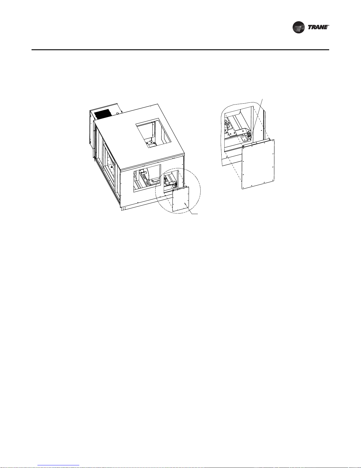
Figure 5. Plug panel plate
Remove Tie Down
Remove Plug Panel Plate
Installation - Mechanical
General Lifting Considerations
WARNING
Heavy Objects!
Always place, assemble, and suspend sections/subassemblies one at a time. Do not lift units in
windy conditions. Do not raise units o verhead with personnel below unit. F ailu r e to foll ow th ese
instructions could result in death, serious injury, or equipment damage.
WARNING
Improper Unit Lift!
Test lift unit approximately 24 inches to verify proper center of gravity lift point. To avoid
dropping of unit, reposition lifting point if unit is not level. Failure to properly lift unit could
result in death or serious injury or possible equipment or property-only damage.
NOTICE:
Equipment Damage!
Keep skid in place until unit is r eady to set. Do not mo ve unit or su bassembly without the skid in
place as shipped from the factory. Premature skid removal could result in equipment damage.
Before preparing the unit for lifting, estimate the approximate center of gravity for lifting safety.
Because of placement of internal components, the unit weight may be unevenly distributed, with
more weight in the coil and fan areas. Approximate unit weights are pro vided in “Unit Dimensions
and Weights” on page 16. Refer to the unit submit tals for actual section weights. Test the unit for
proper balance before lifting.
For outdoor air handlers, preparation of the roof curb or pier mount and roof openings must be
completed before lifting to the roof. S e e CLCH-SVN04A-EN Roof Curbs for Performance Climate
Changer Air Handlers installation instructions for details.
CLCH-SVX07C-EN 25
Page 30
Installation - Mechanical
Rigging and spreader
bars furnished
by others
WARNING
Heavy Objects!
Do not use cables (chains or slings) except as shown. Each of the cables (chains or slings) used
to lift the unit must be capable of suppor ting the enti r e w eight of the unit. Lifting cables (chains
or slings) may not be of the same length. Adjust as necessary for even unit lift. Other lifting
arrangements may cause equipment or property-only damage. Failure to properly lift unit could
result in death or serious injury.
Always rig subassemblies or sections as they ship from the factory. Never bolt sections together
before rigging.
• Make the loop of the sling parallel to the direction of airflow, if possible.
• When hoisting the unit into position, use the proper rigging method, such as straps, slings,
spreader bars, or lifting lugs for protection and safety. Use all lifting lugs provided.
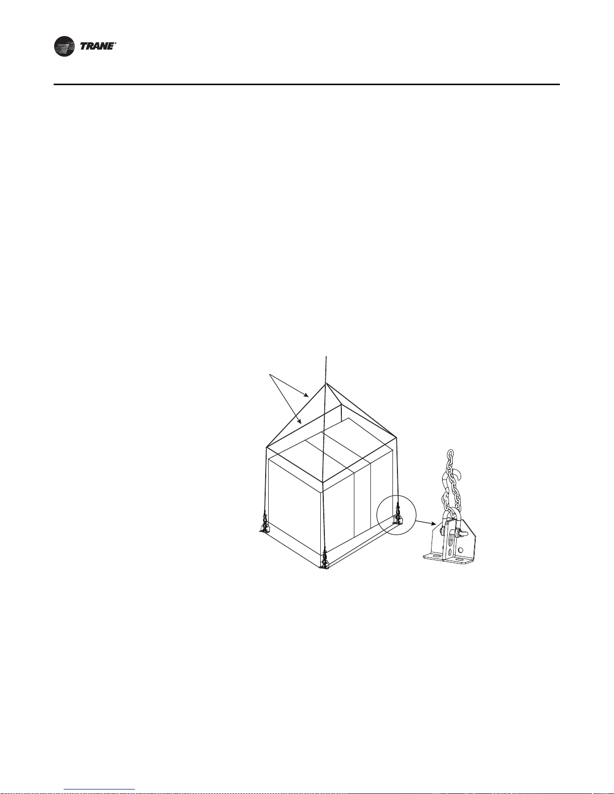
• For unit sizes 3 to 120 with integral base frame, use field-provided spreader bars and slings to
rig units and subassemblies as shown in Figure 6. The air handler is not designed to be lifted
or rigged from the top of the unit.
Figure 6. Lifting detail for unit sizes 3 to 120
26 CLCH-SVX07C-EN
Page 31

Installation - Mechanical
Unit lug
Pipe cabinet
or hood lug
Diameter
Width
Height
Figure 7. Lug holes
Table 8. Lug hole sizes
Section Location Unit Size Width Height
Indoor 3-30 0.88 1.38
Unit Lug
Hole Size
Pipe Cabinet Outdoor 3-120 2.5-in. diameter
Hood Outdoor 3-120 1-in. diameter
Indoor 35-57 1.38 1.25
Indoor 66-120 1.25 2.75
Outdoor 3-30 1.25 2.75
• \For outdoor air handlers, never stack the pipe cabinet or inlet hood on the unit as it is being
lifted.
• Do not attach the intake/exhaust hood or pipe cabinet to the unit prior to lifting the unit. Doing
so may damage the equipment. Attac h the hoods to the unit only after all sections are in place.
• For outdoor air handlers, all shipping supports and crating on the face of the sections must be
removed to permit proper fit-up and sealing of the surfaces. Dispose of properly.
Lifting Inlet and Exhaust Hoods and External Pipe Cabinet (Chase)
WARNING
Heavy Objects!
Always place, assemble, and suspend modules/subassemblies one at a ti me. Placing,
assembling, and/or suspending more than one module/subassembly at a time could result in
death, serious injury, or equipment damage.
See Figure 7 and Table 8 for lug hole sizes.
Figure 8. Inlet and exhaust hood lifting Figure 9. Pipe cabinet lifting
CLCH-SVX07C-EN 27
Recommended
attachment to
lift lugs
Rigging and spreader
bar provided by
contractor
Recommended
attachment to
lifting lugs
Page 32
Installation - Mechanical
48 in.
Wooden toe
cleat or metal
cross beam
Unfasten external bracket
to remove wooden toe cleat.
Forklifting Considerations for Indoor Units Size 3-30
NOTICE:
Equipment Damage!
Improper use of f o rk lifts could r e sul t in eq uipment damage. Fork l ifting from any location other
than that recommended by Trane and indicated on the unit labels could result in unit damage.
Trane is not responsible for equipment damage resulting from improper forklifting practices.
Note: Do not use a forklift on outdoor air handlers or indoor air handlers/subassemblies larger
than size 30.
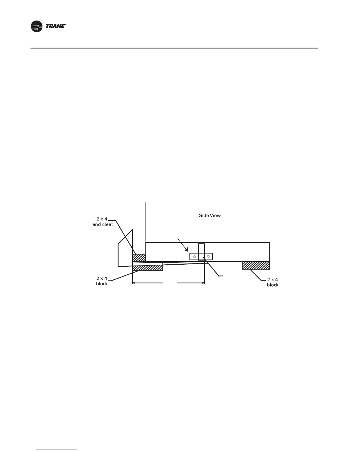
For unit sizes 3-30, a fork lift may be used to lif t a single section or smal l subassembly, provided the
forks extend under both ends of the base frame, or as indicated in Figure 10. The forks should not
contact the bottom of the air handler. Units should only be lifted from the proper end identified by
the lifting label on the unit.
A lifting crane or other means should be used for larger units where forks cannot extend under bo th
base rails.
Figure 10. Fork lift points with base rail
Unit Placement and Assembly
If the air handler ships in subassemblies or in individual sections, some assembly is required,
including:
• Ceiling-suspended indoor unit assem bly; see See “Ceiling Suspension f or Indoor Air Handlers
Sizes 3-57” on page 30.
• Section-to-section assembly; see “Section-to-Section Assembly” on page 32.
WARNING
Toxic Fumes!
Keep open flame away from unit exterior or interior. Do not weld or use cutting torch on the
28 CLCH-SVX07C-EN
exterior or interior of the unit. The unit contains polyurethane insulation. Failure to keep open
flame away form unit exterior or interior could result in the production of toxic gas that could
result in death or serious injury.
Page 33

Unit Placement
Installation - Mechanical
NOTICE:
Temperature Limit!
The internal sections of this unit containing electrical components must not exceed 104o F
operating temperature. Internal sections of the unit not containing electrical components must
not exceed 200o F temperature. Failure to comply with temperature requirements could cause
equipment damage.
WARNING
Heavy Objects!
Always place, assemble, and s uspend sections/subassemblies one at a time. Placing, assembling,
and/or suspending more than one section/subassembly at a time could result in death, serious
injury, or equipment damage.
NOTICE
Microbial Growth!
The roof curb or foundation must be level and the condensate drain at the proper height for
proper coil drainage and condensate flow. Standing water and wet surfaces inside the
equipment can become an amplification site for microbial growth (mold), which may cause
odors and damage to the equipment and building materials.
If a unit arrives in sections, then eac h section must be individually hoisted, set on the housekeeping
pad, roof curb, or pier mount and then assembled.
Refer to the unit submittals and unit tagging for co r rect placement of all sections. If there are any
discrepancies between the submi ttals and the unit tagging, contact your local T rane representative
before proceeding.
Following the order of the sections on the unit submittals and tagging, individually place each
unassembled section or subassembly in the appropriate installation location.
Note: Prior to placing fan section in the appropriate installation location, verify shipping tie-downs
have been removed.
For outdoor units, the pipe cabinet must also be mounted as an individual section. Refer to “Pipe
Cabinet Installation” on page40 for specific instructions.
When mounting the unit on a roof curb, make sure the gasketing between the roof curb and unit
base provides an airtight seal.
When mounting the unit on a pier mount, locate one pier at each corner as a minimum, directly
underneath any shipping split (ensure full support under each side) and then every four feet at
equally spaced intervals around the perimeter of the unit. Both the unit and the pipe cabinet should
be supported by their base around the entire perimeter. See Figure 11 and Figure 12.
For proper operation, the unit must be installed level (z ero tolerance) in both horizontal axes. For
vertical discharge units, allow space under the unit for supply air ductwork connections.
CLCH-SVX07C-EN 29
Page 34

Installation - Mechanical
Piers
4 ft
Figure 11. Piers located in each corner and spaced
evenly eve ry four feet
Note: Piers beneath shipping splits must be structurally sound to support the weight of the unit.
Figure 12. Side view with two shipping splits - locate one
pier directly under each shipping split
Unit Assembly
Note: Air handlers often include optional factory-provided casing penetration entry points for
field-provided wiring. Consider overall unit serviceability and accessibility before
mounting, running wires (power), making cabinet penetrations, or mounting any
components to the cabinet.
See “Component Installation Requirements” on page 49 for special assembly/installation
considerations.
Removing the Shipping Skid
Remove the wooden shipping blocks, wooden toe cleat if there is one, and end cleats prior to
lowering unit into final position or installing the unit to the roof curb.
Ceiling Suspension for Indoor Air Handlers Sizes 3-57
Note: Ceiling suspension is not recommended for units larger than size 57 unless using a field-
provided mounting frame.
Using a Field-Provided Mounting Frame
WARNING
Heavy Objects!
If a field-provided mounting frame is used for ceiling suspension, the installer/contractor must
provide a ceilin g-suspended mountin g frame d esigned t o suppor t the leng th, width, an d w eight
of the entire air-handling unit. Failure to use proper mounting frame, structural channels, and
hangers could result in unit falling from its mounting location which coul d result in death or
serious injury.
See “Unit Dimen sions and Weights” on page 16 for approximate weights.
Note: It is the building engineer’ s responsibility to size the structural c hannels and to pro vide the
appropriate hangers.
Structural channels in a field-provided frame can be mount ed parallel to airflow or perpendicular
to airflow:
30 CLCH-SVX07C-EN
Page 35

Installation - Mechanical
• For parallel-to-airflow channels, size channels based on a four-point load distribution (see
Figure 13.
• For perpendicular-to-airflow channels, size channels based on the load distribution of the
individual sections and install the channels so that both ends of every section are supported
(see Figure 14).
Figure 13. Typical suspension method using parallel
channels
Using Integral Base Frame
If using the factory-provided integral base frame for ceiling suspension, individual sections and/
or subassemblies will have base frame shipping splits and base frame lif ting lugs. When using the
base frame for ceiling suspension:
• Suspend the unit (on both sides of the unit) at each shipping split lug as well as the four corners
of the unit (see Figure 15). See Figure 7 and Table8 on page 27 for lug hole sizes.
• Bolt shipping splits together.
Note: The hanger rods must extend through the bottom of the bas e lug. It is the buil din g
engineer’s responsibi lit y to pr ovide the appropriate hangers.
Figure 15. Ceiling suspension for unit sizes 3-57
Figure 14. Typical ceiling suspension using perpendicular
channels
CLCH-SVX07C-EN 31
Hole diameter
is 0.625 inches
Page 36

Installation - Mechanical
Indoor units - Gasket
0.375 in. T x 0.750 in. W (3-30)
1.0 in. T x 1.0 in. W (35-120)
Outdoor units - Butyl tape
0.375 in. T x 0.375 in W (3-120)
Section-to-Section Assembly
Air handlers ship with all necessary assembly hardware and gasket material. The hardware should
be packaged in either a clear plastic envelope or cardboard box inside the fan section, access
section, or mixing box.
The number of sections to be assembled often makes it necessary to use more than one section
to ship the assembly material; therefore, c heck all sections thor oughly before contacting your T rane
sales representative to report missing items.
Sections are joined with gasketing applied to one of the mating surfaces and hardware to bolt the
sections together. The gasketing for section-to-section joints is a closed cell foam with adhesive
backing.
To assemble the unit:
1. Locate the mounting hardware and gasket material.
2. All shipping supports and crating on the face of the sections must be removed and discarded
to permit proper fit-up and sealing of the surfaces. R emo ve an y ship ping bol ts located on th e
mounting surfaces of the sections (see Figure16).
3. Apply the gasketing to one of the mating surfaces; see Figure 16, Figure 17, and Figure 18.
Figure 16. Section-to-section installation
32 CLCH-SVX07C-EN
Page 37
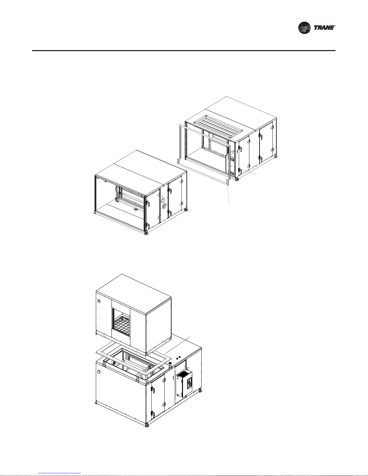
Installation - Mechanical
Butyl Tape
0.380 in. T x 0.380 in. W
Gasket
0.375 in. T
x
0.750 in. W
Gasket
1.00 inches T
x
4.00 inches W
Figure 17. Coil-section-to-downstream-section bolt up with splash guard (shown for sizes 3-30)
Figure 18. Stacked unit assembly (shown for sizes 3-50)
CLCH-SVX07C-EN 33
Page 38

Installation - Mechanical
Use 2 x 4 inch wood to protect
hands from accidental pinching
Wedge block
Figure 19. Horizontal section-to-section quick connects 4. If the unit is equipped with factory-
mounted controls, move adjacent
subassembly within six inches and fasten
quick connects where the sections bolt
together (see Figure 19).
Note: Reference the appropriate controller
manual for more details on the
installation of units with factorymounted controls.
5. Use a bar clamp to pull adjacent shipping section lifting lugs together.
Figure 20. Wedge block attachment 6. F or indoor units sizes 66-120 and for outdoor units
size 10-120, a wedge block is provided to aid in
pulling and aligning the units together . Attac h the
wedge blocks to both sides of the units being
pulled together , matching the corr ect wedge block
with the correct hole pattern. See Figure 20.
Screw
0.250-14 x 0.75
Leached self-driller
7. Verify that the subassembly with the overhang profile on the roof is higher than the mating
subassembly. If it is not, raise one end of the subassembly and bring the unit together. S e e
Figure 21. In addition, an adjustment can also be made to the height of the roof of either
subassembly by loosening the screws in the vertical channels or component structure and
adjust the height of the roof (see Figure 22 and Figure 23).
34 CLCH-SVX07C-EN
Page 39

Installation - Mechanical
At the center (widthwise) of the unit,
measure the height of each adjacent
subassembly and verify that the subassembly
with the overlap sheet metal is higher than
the mating subassembly roof. If it is not,
adjust the height of either subassembly by
loosening the screws in the vertical channels
or component structure and adjust the height
of the roof.
Loosen screws along
width of unit for roof
height adjustment.
8. Due to unlevel floor and platforms, the roof may be misaligned as shown in Figure 21. A
common solution is to raise one end of the shippi ng section to clear the hemming before pulling
the units together.
Figure 21. Roof alignment (indoor unit only)
Figure 22. Adjust height of roof by adjusting vertical channels
CLCH-SVX07C-EN 35
Page 40

Installation - Mechanical
Nut 0.313 - 18
hex flange (HW)
Bolt 5/16 x 6 inch
hex machine bolt
fully threaded zinc plated
Washer
0.375 ID x 0.875 OD
Figure 23. Adjust height of roof by loosening screws
At the center (widthwise) of the unit,
measure the height of each adjacent
subassembly and verify that the
subassembly with the overlap sheet
metal is higher than the mating subassembly
roof. If it is not, adjust the height of either
subassembly by lossening the screws in the
vertical channels or component structure
and adjust the height of the roof.
Loosen screws along
width of unit for roof
height adjustment.
9. For unit sizes 3-30, bolt the unit base frames together using 5/16-inch bolts (see Figure 24).
Figure 24. Base frame split assembly for sizes 3-30
10. For unit sizes 35-120, bolt the unit base frames together using ½-threaded rod (see Figure 25).
36 CLCH-SVX07C-EN
Page 41

11. For sizes 66-120 only, bolt through the wedge blocks using a ½-threaded rod (see Figure 25).
Wedge block
Rod
0.500-13 x 10.50 thd
Bolt
0.500-13 x 10-in hex
machine bolt
fully threaded zinc plated
Washer
0.656 id x 0.312 od
Lifting lugs
Nut
0.500-13 hex flange (HW)
Nut
0.500-13 hex mach
Washer
0.656 id x 1.312 od
Alternate between tightening on the lifting lug bolts and wedge block bolts until the shipping
section comes together.
Figure 25. Wedge block attachment used for sizes 66-120 only
Installation - Mechanical
CLCH-SVX07C-EN 37
12. Use straps and come-alongs to compress the gasketing and pull the sections together along the
height of the unit.
Page 42

Installation - Mechanical
See detail
Seam cap
Butyl tape
13. Install the section-to-section screws inser ting the appropriate screws through the o verlapping
flanges using a powered impact gun and taking care not to strip the screws. Outdoor air
handlers will ship with a seam cap that is to be installed over the section-to-section seams.
Factory-supplied butyl tape must be applied over the seam prior to seam cap being applied. See
Figure 26.
Figure 26. Section-to-section seam cap installation
38 CLCH-SVX07C-EN
Page 43
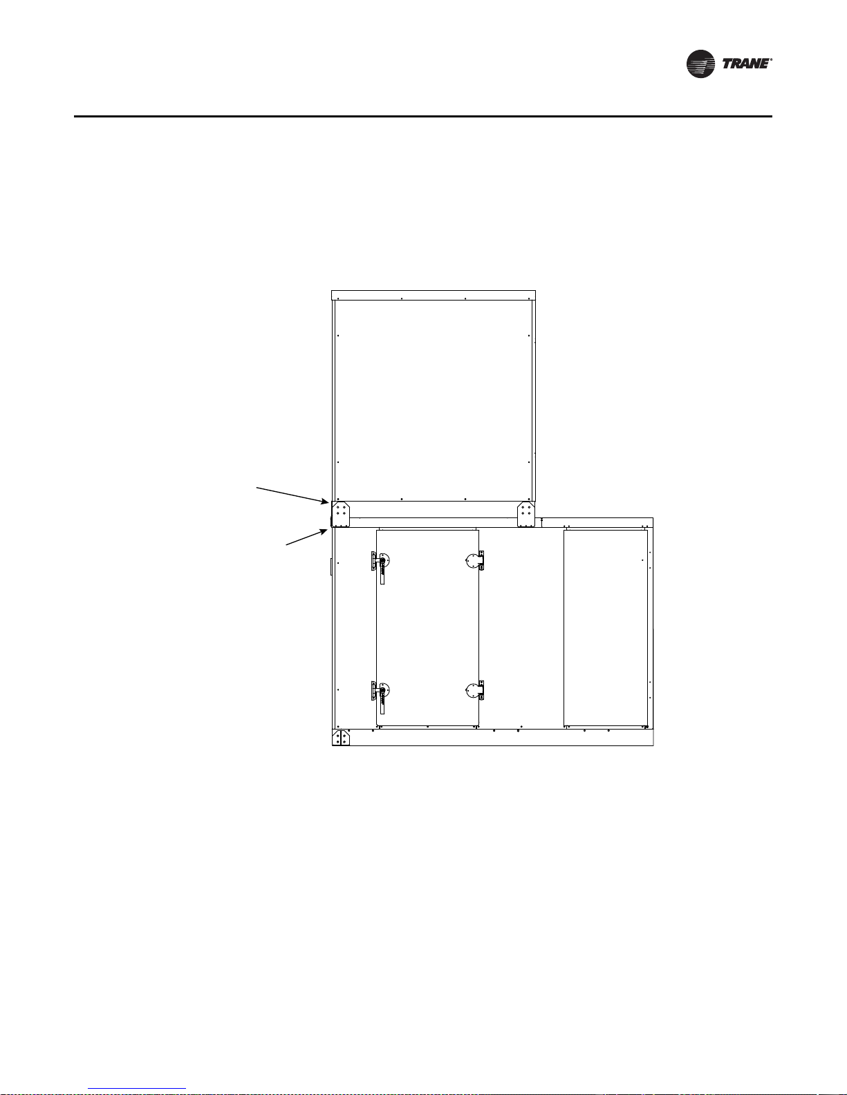
Installation - Mechanical
X25020634020
Screw: #10-16X 0.75 in.
Sheet Metal Hex Head
Qty:3
X25240049010
Screw: .313-18X0.875 in.
Sheet Metal Hex Head
Qty: 4
14. For stac ked units, remove top level lifting lugs one at a time and replace with factory-provided
stacking brackets at each shipping split corner and end of unit perpendicular to airflow after
sections are set in final position (see Figure 27). Be sure to compress the gasketing to ensure
a good air seal between the upper and lower sections.
Figure 27. Stacked unit hardware
CLCH-SVX07C-EN 39
Page 44

Installation - Mechanical
See detail
Butyl tape
15. For outdoor air handlers, attach roof overhang angle with number 10 screws. J oin outdoor roof
panels together at the seams in the direction perpendicular to airflow and secure them in place
with 5/16-inch x 3/4-inch bolts and 5/16 lock nuts. Install the roof joint strip to cover the seam
between two outdoor roof panels in the perpendicular to airflow direction of. Use 3/8-inc h butyl
tape to cover the seam between two outdoor roof panels overhang at the side the unit. Bend
joint strip over roof panel and use t wo number 10 sheet metal screws (one in eac h roof panel)
to secure joint strip. T rim the roof joint strip to insure that it does not pro trude more than 1/16inch beyond outdoor roof overhang (see Figure 28).
Figure 28. Join outdoor roof panels at the seams
Pipe Cabinet Installation
1. After air handler is completely installed and checked for accuracy of level and square, pipe
cabinet install can begin.
2. Remove pipe cabinet base cross member by removing the four bolts and nuts.
3. Check to ensure that the structure the pipe cabinet is to be installed on is square and level.
40 CLCH-SVX07C-EN
Page 45
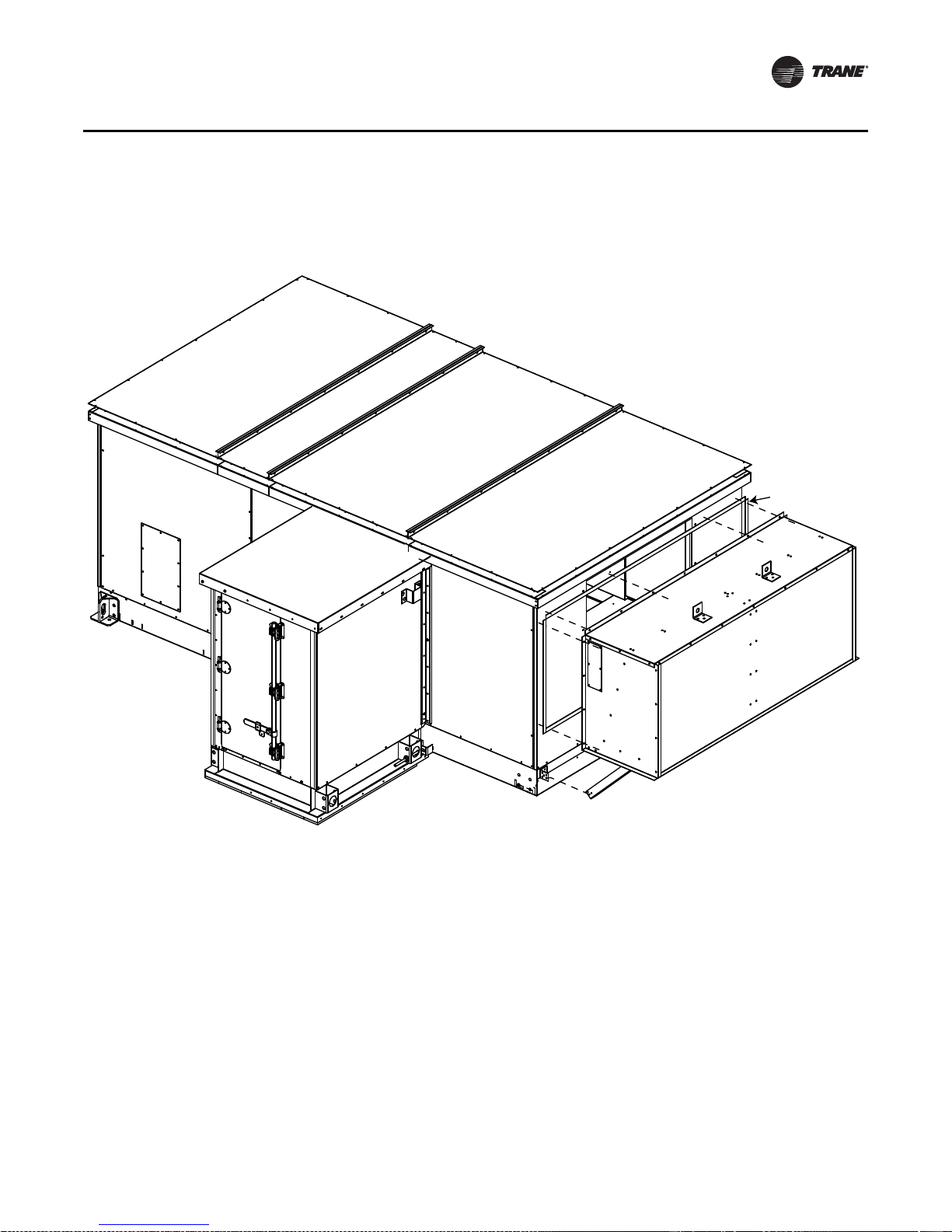
4. Install 3/8-inc h x 3/8-inch white butyl tape to flanged side of pipe cabinet wall and remove paper
Butyl tape
backing from tape. See Figure 29.
Figure 29. Pipe cabinet installation
Installation - Mechanical
5. Lift cabinet into place on to pipe cabinet curb.
6. Slide pipe cabinet tight up against the sidewall of the air handler.
7. Check pipe cabinet side walls to ensure they are plumb.
8. Apply a bead of caulk along the corner between the pipe cabinet and air handler wall prior to
installing connecting angle.
CLCH-SVX07C-EN 41
Page 46

Installation - Mechanical
TOP VIEW
A
DETAIL A
DETAIL B
See Detail B
AHU
Pipe Cabinet
Ribbed Butyl tape
Screw 10-16 x .750 self-driller
Pipe cabinet outer roof
Slots provided to allow
final adjustment of outer roof
AHU outdoor roof
Inside corner cap
Ribbed Butyl tape
(see Note 1)
Roof and base parts
removed for clarity
Ribbed Butyl tape
Ribbed Butyl tape
(see Note 1)
Inside corner cap
Pipe cabinet wall
Note:
1. Seam to be sealed with three-ribbed Butyl tape
prior to attaching inside corner cap with screws
(10-16 x .750 self-driller).
9. Install inside corner cap. See Figure 30 Detail A and B.
10. Install 3/8-inch x 3/8-inch white butyl tape to unit wall where pipe cabinet roof connects.
11. Lift pipe cabinet roof into place and attach to unit wall with screws. See Figure 30.
Figure 30. Pipe cabinet
Outdoor Unit Weather Hood(s)
1. Per the unit drawing determine mounting location of the unit weather hoods.
2. Using the factory provided screws mount the weather hoods to the unit.
3. On larger units, weather hoods may be large enough to require angled down supp orts. In those
cases, the angles are shipped attached to the hood but will need to be connected to the air
handler by the installing contractor. See Figure 31.
Note: It is required that the hoods be sealed to the unit using factory-provided butyl/caulk tape.
42 CLCH-SVX07C-EN
Page 47

Figure 31. Hood installation
AHU outdoor roof
Butyl caulk tape
1.00 W x .125T.
Hood
Nut-Hex .31-18
Detail A
Screw self-driller
10-16 x .750
Butyl caulk tape
1.00 W x .125T.
Nut-Hex .31-18
Bolt .313-18 x .750 Hex
Bracket Support
Angle Hood Support
(when required)
Bolt .313-18 x .750 Hex
Installation - Mechanical
Indoor Dual-Path Split Dehumidification Unit (SDU)/Winterizer
Assembly
WARNING
Heavy Objects!
Do NOT stack air handlers unless factory-designed and factory-approved. When stacking units,
factory-designed unit support brackets must be used. Stacking units without factory-approval
and without using factory-provided support brackets could result in the base unit collapsing
under the weight of the top unit which could result in death, serious injury and equipment
damage.
A dual-path, SDU/winterizer air handler consists of two units that are stacked together in a drawthru arrangement that share one supply fan. The unit on the first level (primary unit) is designed
to handle the return air and is larger than the unit on the second level (secondary unit), which is
designed to handle outside air.
Factory-designed unit support brackets are provided with all factory-approved, dual-path SDUs or
winterizer air handlers.
• A horizontal SDU/winterizer dual-path air han dler incorpo rates a horiz o ntal supply fan on the
first level with a top opening in the primary unit that aligns with a bottom opening in the
secondary unit.
• A vertical SDU/winterizer dual-path air handler incorporates a vertical supply fan on the second
level with a back opening that aligns with a front opening in the secondary unit.
CLCH-SVX07C-EN 43
Page 48
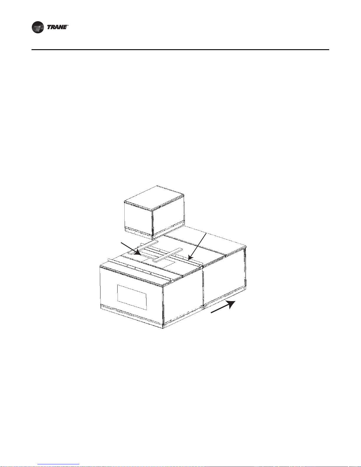
Installation - Mechanical
Unit support
brackets
Gasket
1.0 inches T x
4.0 inches W
Airflow
To assemble air handlers utilizing factory-approv ed and factory-provided dissimilar unit sizes for
horizontal SDU or winterizer applications, join all similar size shipping sections per “Section-toSection Assembly”, Step 1 through Step 13, p. 32 through p. 39.
Horizontal SDU/Winterizer Indoor Air Handler Assembly
To assemble dissimilar unit sizes in a horizontal SDU/winterizer configuration:
1. Locate the mounting hardware and gasket material.
Note: Black unit support brackets ship pre-installed on the prima ry (larger) unit section.
2. Apply gasket in direction of airflow between the black unit support brackets to the roof of the
primary unit. See Figure 32. The gasket needs to be placed such that it will be directly under the
integral base frame of the secondary (smaller) unit to be stacked on top. The secondary unit w ill
be centered along the width on the primary unit.
Figure 32. Apply gasket in direction of airflow
3. If there is an opening in the roof of the primary unit, apply gasket perpendicular to airflow on
the roof next to the opening (air entering side only).
44 CLCH-SVX07C-EN
Page 49

Installation - Mechanical
Center of units
Secondary Unit
Gasket
Primary Unit
Airflow
X25240049010
Screw: 0.313-18 x 0.875 in.
Sheet metal hex head
4. Lift the secondary unit, following instructions in “General Lif ting Considerations” on page 25
(see Figure 6), and place on the black unit support brac kets (see Figure 33). The secondary unit
must be centered on the primary unit between the black unit support brackets.
Figure 33. Place secondary unit on black unit support brackets.
5. Install screws as shown in Figure 34 inserting the appropriate screws using a powered impact
gun and taking care not to strip the screws.
Figure 34. Install screws using powered impact gun.
6. Remove the secondary unit lifting lugs one at a time and reinstall screws after sections are set
in final position.
CLCH-SVX07C-EN 45
Page 50

Installation - Mechanical
Airflow
Gasket
1.0 inches T x 1.0 inches W
Vertical SDU/Winterizer Indoor Air Handler Assembly
To assemble dissimilar unit sizes in a vertical SDU/winterizer configuration:
1. Apply gasketing to the mating surface of the secondary unit (see Figure 35).
Figure 35. Apply gasketing to mating surface of secondary unit.
46 CLCH-SVX07C-EN
Page 51

Installation - Mechanical
Airflow
Vertical and horizontal
trim angles
Airflow
2. Apply gasketing to the mating surface of the primary unit at the bottom of the opening (see
Figure 36.
Figure 36. Apply gasketing to the mating surface of the primary unit.
Gasket
1-inch T x
2 1/2 inch W
3. Lift the secondary unit, follow instructions in “General Lifting Considerations” on page 25 (see
Figure 6), and place on the blac k unit support brackets (see Figure 33, p. 45. The secondary unit
must be centered on the primary unit between the black unit support brackets.
4. Install trim angles as shown in Figure 37 inserting the 10- 16 x 3/4-inc h self-drilling screws using
a powered impact gun and taking care not to strip the screws.
Figure 37. Install trim angles
CLCH-SVX07C-EN 47
Page 52

Installation - Mechanical
Cut zip-ties
Step 1
Match connector
numbers (LV side)
Match connector
colors (HV side)
High-voltage (HV)
stacked harness
Low-voltage (LV)
stacked harness
Step 2
Verify if conduit is
1-inch or 2-inch for
stacked harness
Use for 1-inch stacked
raceway conduit
Use for 2-inch stacked
raceway conduit (requires
removal of knockout)
Cover
Conduit
Step 3
Wrap around
conduit when
attaching cover
Screw; 10-16 x 0.75
self-driller
Enclosure;
stacked raceway
Step 4
Tie; 0.25 wire screw type
Screw;
.250-14 x 0.75
self-driller
Space tie downs
no greater than
10 inches. Also
locate cut-screw
behind conduit
Step 5
External Raceway Assembly
For air handling units with factory-installed power wiring extending from the first level to the
second level, wiring must be connected and assembled in a raceway.
1. Remove protective foam cover from connectors.
2. Attach stacked raceway harness connectors, matching connector colors on th e high voltage
side and connector numbers on the low voltage side.
3. Verify conduit size.
4. Attac h covers.
5. Secure conduit.
Figure 38. External raceway
48 CLCH-SVX07C-EN
Page 53

Component Installation Requirements
Airflow
Component Installation Requirements
The components in the air handler may have installation requirements that could affect the unit’s
performance.
Diffuser Sections
Diffuser sections are usually placed between a fan and a downstream coil or filter. Because
placement is critical to unit perfor mance, verify the correct placement of the diffuser section before
assembling the unit (see Figure 39).
Figure 39. Diffuser placement sizes 3 to 120
Filter Sections
Bag and cartridge filter sections can be used as a pre-filter section, a final filter section, or both. This
use is determined by the filter’s placement in relation to the fan.
• A final filter is placed after the fan.
• A pre-filter is placed before the fan.
Note: Cartridge and bag filters provided by Trane are fit ted with a 7/8-inc h header that fits in the
filter track. If using filt ers supplied by another manufacturer, filters should be purchased
with a 7/8-inch header. In some cases it may be necessary to gasket other manufacturers’
filters to ensure a good air seal.
Filters should be installed when the unit is set. This will protect internal components, such as the
heating and cooling coils.
Final Filter Section
A final filter section should not be bolted directly to the face of a fan section. One or more
intermediate sections must be placed between the fan discharge and the filter section.
Pre-Filter Section
A pre-filter section has no special installation requirements unless placed directly upstream of a
plenum fan. In these configurations, ensure a blank s ection is placed between the fan inlet and the
filter section.
Trane recommends the use of disposable pre-filters with high-efficiency filters. Disposable prefilters slide into the mounting tracks just ahead of the bag/cartridge filters.
CLCH-SVX07C-EN 49
Page 54

Component Installation Requirements
Filter Installation
WARNING
Hazardous Voltage!
Disconnect all electric power, including remote disconnects before opening door. Follow proper
lockout/tagout procedures t o ensure the equipment cannot be inadvertently energized. Failure t o
disconnect power before servicing could result in death or serious injury.
Figure 40. Filter block-of f pl acement To install filters:
1. Disconnect the power to the unit.
2. Open the filter section access door.
3. Slide the filters into the tracks.
Note: Bag filters must be installed with the pleats in the
vertical plane.
4. The block-off is permanently installed and will create a
seal when the access door is closed.
5. Close the access door slowly to allow any gasketing to
compress.
50 CLCH-SVX07C-EN
Page 55

Filter Placement
Size 14
20
3
20
20
20 25
18.06 ft
²
Size 17
16
16
20
20 25
16
16
3
28.89 ft
²
Size 12
20
20
20
20
20 2.5
16.67 ft
²
16
25
25
25
1
Size 21
16
16
16
33.33 ft
²
Size 25
251625 25 1
16
16
16
16
16
50.00 ft
²
Size 35
25 25 25 20 1
16
16
16
16
16
16
63.33 ft
²
Size 30
16
20
16
16
16
16
16
20 20 25 4.5
56.67 ft
²
Size 40
201620 20 25 3.520
16
16
16
16
16
70.00 ft
²
Size 50
20
20 20 20 20 20 20 1.5
20
20
20
20
20
100.00 ft
²
Size 3
16
25
2.5
16
5.56 ft
²
Size 4
16
20 20
16
8.89 ft
²
20 20
Size 8
20
6.5
20
11.11 ft
²
Size 10
25 25 7.25
20
20
13.89 ft
²
Size 6
16
20 20
16
8.89 ft
²
Figure 41 . 2-inch and 4-inch angled filter placement for unit sizes 3-50
Component Installation Requirements
CLCH-SVX07C-EN 51
Page 56

Component Installation Requirements
Size 57
20
20 1.5
20
20
20
20
20
2020202020
100.00 ft
²
Size 66
20
16 .5
20
20
20
20
20
202020202020
113.33 ft
²
Size 80
16 .5
20
20
20
20
20
20
20
20
202020202020
151.11 ft
²
Size 100
20
25 25 25 25 25 25 .5
20
20
20
20
20
20
20
166.67 ft
²
Size 120
20
25 3
20
20
20
20
20
20
20
252525252525
194.44 ft
²
Figure 42. 2-inch and 4-inch angled filter placement for unit sizes 57-120
52 CLCH-SVX07C-EN
Page 57

Component Installation Requirements
Size 3
20
24
3.9
3.33 ft
²
Size 4
20
20 .8
20
5.56 ft
²
20 20
Size 6
24
.8
6.67 ft
²
12 12
Size 8
24
.112 12
8.00 ft
²
Size 10
20
20
6.45
24
12
8.67 ft
²
Size 12
12
20
20
20
20 3.7
2424 15.3
12.33 ft
²
Size 14
24
1.2
12
20
24 20
20.82424
13.44 ft
²
Size 17
20
20
24
24 20
1.2
18.89 ft
²
20
24
5.2
242424
Size 21
22.00 ft
²
24
20
20
12
24 24 5.2
Size 25
26.00 ft
²
12
20
18.7
20
20
11.1
Size 30
24 24 24
20 20 20
28.22 ft
²
Size 35
24
20
20
12
24 24 24
1.6
34.67 ft
²
Size 40
24
24
24
2.524 24 24 12
36.00 ft
²
Size 50
12
24
24
24
3.5
24 24 24 24
50.00 ft
²
Figure 43. Bag and cartridge side-loading filter placement for unit sizes 3-50
CLCH-SVX07C-EN 53
Page 58

Component Installation Requirements
Size 57
24
24
24
24
3.524 24 24 24
60.00 ft
²
Size 66
20
24
20
20
20
24 24 24 24 18.5
66.67 ft
²
Size 80
24
24 6.9
24
24
24
24 24 24 24 12
88.00 ft
²
Size 100
12
20
24
1.7
24
24
24
24 24 24 24 24 24 8.9
20 20 20 20 20 20 12
111.33 ft
²
Size 120
24
24 1.2
12
24
24
24
24 24 24 24 24 24 12
12.8
134.00 ft
²
Figure 44. Bag and cartridge side-loading filter placement for unit sizes 57-100
54 CLCH-SVX07C-EN
Page 59

Figure 45. Flat and combination filter placement for unit sizes 3-50
Size 3
20
25
2.5
3.47 ft
²
Size 4
20
20 20
5.56 ft
²
20 20
Size 6
25
6.94 ft
²
24 20
Size 8
24
2.5
7.33 ft
²
Size 10
20
20
1.25
25
16
9.72 ft
²
Size 12
16
16
20
20
20 2.5
13.33 ft
²
Size 14
20
3
16
16
20 25
14.44 ft
²
Size 17
20
20
24
24 20
18.89 ft
²
16
25
25
25
25
1
16
202020
Size 21
21.53 ft
²
24
20
20
12
16
24 24 4
202020
Size 25
27.11 ft
²
12
24
17.5
20
20
24 24 16
1.5
Size 30
30.44 ft
²
Size 35
24
20
25 25 25 20 1
20
16
24 24 24
37.22 ft
²
Size 40
20
16
20
20
20 20 25 3.520
40.83 ft
²
Size 50
16
25
20
25
25
25 25 25 20
20 20 20 20 20 1.5
55.00 ft
²
Component Installation Requirements
CLCH-SVX07C-EN 55
Page 60

Component Installation Requirements
Size 57
20
25
16
20
20
25 25 25 20
1.5
63.33 ft
²
Size 66
20
24
20
20
20
24 24 24 24 16 .5
75.56 ft
²
Size 80
20
16.5
24 24 24 24 24 16 .5
12
20
20
20
85.56 ft
²
Size 100
20
25
20
20
20
20
25 25 25 25 25 .5
104.17 ft
²
Size 120
25
20
25
25
25
20 20 20 20 20 20 20 16 2
122.22 ft
²
Figure 46. Flat and combination filter placement for unit sizes 57-120
56 CLCH-SVX07C-EN
Page 61

Figure 47. Front-loading bag and cartridge filters sizes 3-50
Size 12
10.38
Size 4
2.00 ft
²
12
24 15.88
10.38
24 12
Size 6
24
3.75
6.00 ft
²
4.63
Size 8
6.00 ft
²
24
24
10.2512
7.13
Size 10
8.00 ft
²
24 24 9.25
24
7.13
Size 25
24
24
24
6.75
24 24 3.63
24.00 ft
²
Size 26
9.2524
24
24
24
24
24.00 ft
²
6.63
Size 30
6.75
24
24
24
524 24 12
28.00 ft
²
24
24
Size 31
24
24
2412 7.63
Size 36
24
24
3.63
24
24
24 24
30.00 ft
²
36.00 ft
²
6.63
6.63
Size 35
24
24
24
12
24 2412 11.5
34.00 ft
²
.38
Size 50
12
24
24
24
.8824 24 24 24
50.00 ft
²
8.88
Size 40
24
24
12
24 24 2424 12
.38
38.00 ft
²
Size 41
24 24 24 3.63
24
24
24
24
46.00 ft
²
1
Size 14
24
7.63
24
24 12
10.00 ft
²
10.88
Size 21
12
24
3.63242424
18.00 ft
²
10
Size 17
12
24
24 24 12 7.63
14.00 ft
²
6.25
Size 22
242424129.25
24
18.00 ft
²
.38
Component Installation Requirements
Size 3
12
24 3.38
²
2.00 ft
10.88
24
24 24 12 2.13
10.00 ft
²
CLCH-SVX07C-EN 57
Page 62
Component Installation Requirements
Size 100
12
24
24
24
24
24 5.7524 24 24 24 24
1.13
106.00 ft
²
Size 120
24
24 9.125
12
24
24
24
24 24 24 24 24 24
1.13
124.00 ft
²
Size 66
10.13
24
24
24
24
24 24 24 3.7524 12
66.00 ft
²
Size 80
24
24 3.75
24
24
24
24 24 24 24 12
1
86.00 ft
²
Size 57
24
24
24
24
.8824 24 24 24
60.00 ft
²
6.63
Size 50
24
24 24 12 5
24
24
24
54.00 ft
²
24
1
Figure 48. Front-loading bag and cartridge filters sizes 57-120
58 CLCH-SVX07C-EN
Page 63

Figure 49. Front-loading HEPA filters sizes 3-50
Size 3
12
24 2.88
2.00 ft
²
Size 4
12
24 15.38
2.00 ft
²
24 12
Size 6
24
2.75
6.00 ft
²
30
Size 8
24
3.2512
7.00 ft
²
Size 10
24 24 8.25
30
10.00 ft
²
Size 12
30
24 24 13.25
10.00 ft
²
Size 14
24 18.75
30
24
10.00 ft
²
12
30
2.125242424
Size 21
21.00 ft
²
Size 17
12
24
30 6.75
14.00 ft
²
24 624
30
6
30
24
24
30 12 2.13
Size 25
24.00 ft
²
30
24
24
3.63
Size 30
30 24
28.00 ft
²
Size 35
30
30
24
30 30 4.13
9
30.00 ft
²
24 24 24
9
Size 40
24
30
24
6
30 30 12
24 24 24
30 4.0
37.00 ft
²
Size 50
12
30
24
24
5.030 30 24
46.00 ft
²
24 24 24 24 9
9
Component Installation Requirements
CLCH-SVX07C-EN 59
Page 64
Component Installation Requirements
Size 57
24
30
24
24
5.030 30 24
57.00 ft
²
Size 100
12
30
30
30
24 2.7524 24 24 24 24
102.00 ft
²
Size 120
24 5.63
12
30
30
30
119.00 ft
²
24 24 24 24 24 24
Size 66
30
24
24
24
30 30 1.38
30 12
66.00 ft
²
Size 80
12
30 1.38
24
24
24
30 30 30 12
76.00 ft
²
24 24 24 24 24 6
6
Figure 50. Front-loading HEPA filters sizes 57-120
60 CLCH-SVX07C-EN
Page 65

Fan Sections
Required
clearance
Required
clearance
The fan section can be configured as either draw-t hru or blow-thru. Review the su bmittals and unit
tagging information prior to assembly to determine placement.
Fan Isolation
The fan-and-motor assembly is internally isolated. The fan and motor bases are bolted to a
minimum of four spring isolators. The isolators are secured to the fan section support base.
Shipping tie-down bolts are bolted adjacent to the isolators between the fan isolation base and the
isolator support frame. The shipping tie-downs secure the isolation base to the support assembly
to prevent any damage to the fan section during shipment.
Note: Remove the tie-downs only if the factory-provided isolation is to be used.
Adjusting the Isolators
Note: For additional information regarding the safe discharge of capacitors, see
Once the shipping tie-downs are removed and the internal isolation is released, it may be necessary
to adjust the isolators to achieve the proper operation height of the fan and motor isolation base.
Minimum required clearances are listed in Table 9. T o determine the isolator clearances on all unit
sizes, measure between the top of the cabinet c hannel and the bottom of the isolation base channel.
See Figure 51, Figure 52, Figure 53, and Figure 54.
Component Installation Requirements
PROD-SVB06A-EN.
Table 9. Minimum isolator clearances (inches)
Unit Size Fan Type Required Clearance
3–8 FC, BC, Plenum 1.0
10–30 FC, AF, Plenum 0.5
35-57 FC, AF, Plenum 0.5
66-120 FC, AF, Plenum 1.0
Figure 51. Isolator tie-down removal for unit sizes 3-8 Figure 52. Isolator tie-down removal for unit sizes 10-30
CLCH-SVX07C-EN 61
Page 66

Component Installation Requirements
Required
clearance
Figure 53. Isolator tie-down removal for unit sizes 66-120 Figure 54. Belt-drive plenum fan tie down
Seismic Isolation Requirements
Air handling equipment manufactured by Trane is capable of structurally and operationally
withstanding the seismic response criteria as required by the International Building Codes (IBC)
2000,2003, 2006, 2009. Trane has third-party certification for IBC compliance for seismic
applications for unit sizes 3-30. Certification for larger sizes is in process.
Note: If seismic isolation has been specified, the following requirem ents must be adhered to for
installation. Failure to follow these instruction would void the warranty.
Required
clearance
Anchor Requirements
Single Level Design Break
Size 3-30 - Grade to Roof Mounted (0<=Sds<=1.85) Non-Isolated
4000 psi concrete
• 3/8-inch diameter Hilti Kwik Bolt TZ carbon steel concrete anchors attached to unit base rails.
• Quantity (2) anchors at AHU ends, (quantity (1) at each side)
• Quantity (2) anchors at AHU unit splits, quantity (1) at each side, staggered.
• 2-inch minimum anchor embedment
• 4-3/8-inch mi nimum distance to the nearest edge
• 4-inch minimum concrete slab thickness
Steel dunnage/steel curb
3/8-inch diameter ASTM A325 or SAE grade 5 bolts attached to unit base located as noted above
or 1-inch long 3/16-inch welds at unit base located as noted above.
Stacked Design Break
Size 3-30 – Grade to Roof Mounted (0<=Sds<=1.85) Non-Isolated
4000 psi concrete
• 1/2-inch diameter Hilti Kwik Bolt TZ carbon steel concrete anchors attached to unit base rails.
• Quantity (2) anchors at AHU ends (quantity (1) at each side).
• Quantity (2) anchors at AHU unit splits, (quantity (1) at each side, staggered).
• 3 1/4-inch minimum anchor embedment
62 CLCH-SVX07C-EN
Page 67
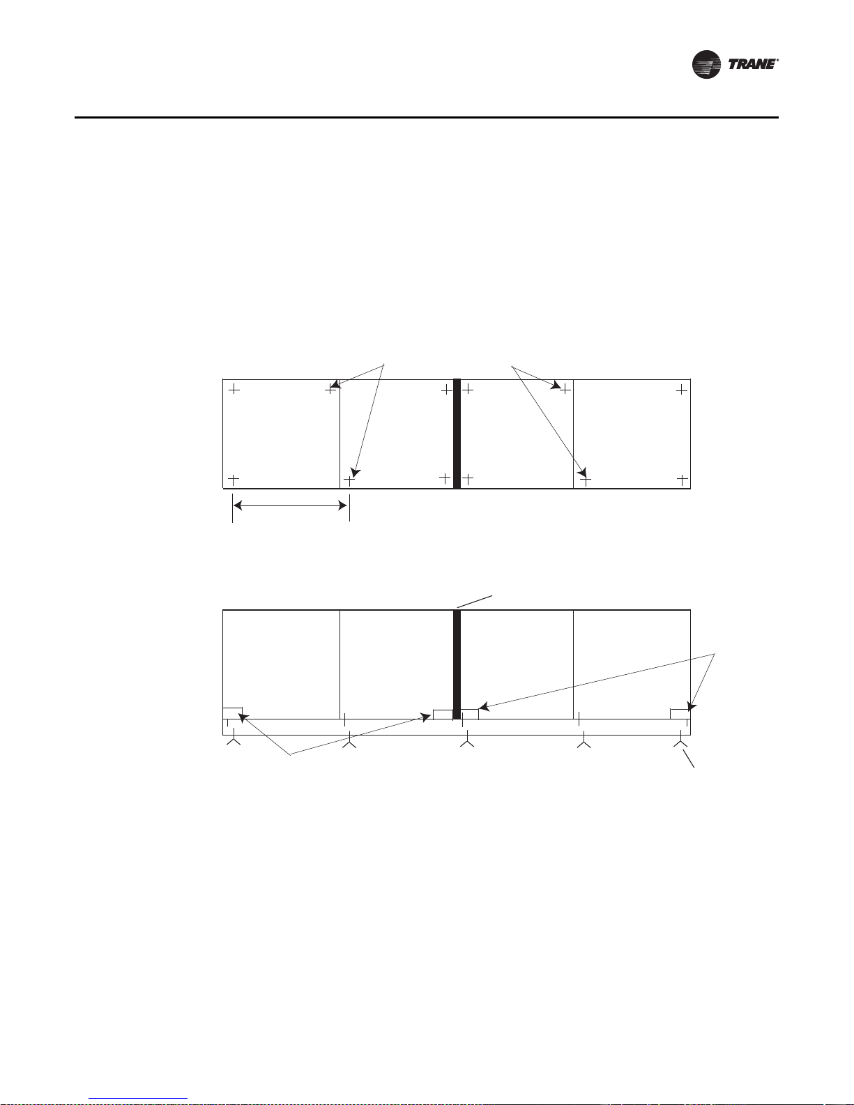
Component Installation Requirements
Section
Base rail
Staggered anchor bolt patterns
Shipping split joint
Lifting
lugs
Anchor bolt
to floor curb
Spacing <= 46 inches*
AHU Plan View
AHU Elevation View
*Only if not anchoring each functional section
Shipping split 1
Shipping split 2
Lifting lugs
Shipping split 1
Shipping split 2
• 7 1/2-inch minimum distance to the nearest edge
• 6-inch minimum concrete slab thickness
Steel dunnage/steel curb
1/2-inch diameter AS TM A325 or S AE Grade 5 bolts at tached to unit base located as noted above
or 1-inch long 3/16-inch welds at unit bases located as noted above.
Anchor Pattern
Figure 55. Seismic anchor pattern
Each module is considered a functional section; for example, fan section, coil section, access
section, etc. Anch oring of the unit needs to be p laced at the designated locations according to the
anchoring pattern for each functional section (see Figure 55).
If anchoring eac h functional section is difficult, then spacing between each anchor can be no longer
than 46 inches.
Lifting lugs can be used as locations for anchoring the unit. For locations that do not have lifting
lugs, additional anchors need to be installed at the construction site.
Anchor selection meets or exceeds IBC 2000, 2003, 2006 and 2009 compliance requirements.
CLCH-SVX07C-EN 63
Special Inspection per IBC Section 1704 is required on all installations. All anchors listed above
must be installed to meet compliance.
Page 68

Component Installation Requirements
Damper Sections
Dampers are factory-installed and adjusted and can be found in mixing box/economiz er sections.
There are two damper blade configurations available: parallel-blade and opposed-blade.
T raq™ dampers are another type of damper available in mixing box sections. Traq dampers have
only one blade configuration - opposed. They have two control applications available - standard
Traq dampers and low-flow Traq dampers. Low-flow Traq dampers are always not linked and
consist of two damper sets - one set for minimum outside air measurement and one set for
economizing. Each will have its own VCM.
The air handler is available with factory-mounted controls or end devices. If the unit is not ordered
with controls or end devices, it is the installer’s responsibility to provide and install the damper
actuators. Size the actuators according to Table 10.
Damper Torque Requirements
Table 10. Mixing box damper torque requirements (inch pound) at 1-inch w.g. air pressure drop
Parallel
Unit
Size
airfoil
damper
only
3 9.00 6.40 18.00 n/a n/a 10.30 7.70 19.30 36.00
4 13.10 9.30 36.00 18.00 18.00 14.90 11.20 37.90 72.00
6 17.10 12.20 36.00 18.00 18.00 19.60 14.70 38.40 72.00
8 23.30 16.60 54.00 18.00 36.00 26.60 19.90 57.30 108.00
10 29.00 20.70 54.00 18.00 36.00 33.20 24.90 58.10 108.00
12 35.70 25.50 67.50 22.50 45.00 40.70 30.60 72.60 135.00
14 39.50 28.20 67.50 22.50 45.00 45.20 33.90 73.10 135.00
17 48.90 34.90 67.50 22.50 45.00 55.90 41.90 74.50 135.00
21 60.40 43.10 99.00 33.00 66.00 69.00 51.80 107.60 198.00
25 72.40 51.70 99.00 33.00 66.00 82.80 62.10 109.30 198.00
30 84.20 60.10 108.00 36.00 72.00 96.20 72.20 120.00 216.00
35 100.20 71.50 108.00 36.00 72.00 114.50 85.90 122.30 198.00
40 110.20 78.70 108.00 36.00 72.00 125.90 94.50 119.60 198.00
50 126.30 90.20 112.50 37.50 75.00 144.30 108.20 135.70 216.00
57 154.80 110.60 112.50 37.50 75.00 176.90 132.70 164.20 198.00
66 177.60 126.80 150.00 37.50 75.00 202.90 152.20 187.00 264.00
80 210.30 150.20 187.50 37.50 112.50 240.30 180.20 223.10 360.00
100 272.00 194.30 225.00 37.50 150.00 310.90 233.20 284.90 396.00
120 322.40 230.30 225.00 37.50 150.00 368.50 276.30 335.20 432.00
Opposed
airfoil
damper
only
Standard
Traq
damper
only
Low-flow
minimum
OA Traq
damper only
Low-flow
econ Traq
damper
only
Parallel airfoil
damper linked
to parallel
airfoil damper
Opposed airfoil
damper linked
to opposed
airfoil damper
Standard
Traq linked
to airfoil
damper
Standard
Traq linked
to standard
Traq damper
64 CLCH-SVX07C-EN
Page 69

Table 11. Side Traq damper - standard flow mixing box
Component Installation Requirements
Unit
size
100 28.00 3 37.50 112.50 160 1 No Yes
120 24.00 4 36.00 144.00 160 1 No Yes
Damper
dia (in)
3 13.00 1 18.00 18.00 42 1 No No
4 13.00 1 18.00 18.00 42 1 No No
6 13.00 1 18.00 18.00 42 1 No No
8 13.00 1 18.00 18.00 42 1 No No
10 16.00 1 22.50 22.50 42 1 No No
12 16.00 1 22.50 22.50 42 1 No No
14 13.00 2 18.00 36.00 42 1 No Yes
17 13.00 2 18.00 36.00 42 1 No Yes
21 16.00 2 22.50 45.00 160 1 No Yes
25 16.00 2 22.50 45.00 160 1 No Yes
30 20.00 2 33.00 66.00 160 1 No Yes
35 20.00 2 33.00 66.00 160 1 No Yes
40 20.00 2 33.00 66.00 160 1 No Yes
50 24.00 2 36.00 72.00 160 1 No Yes
57 24.00 2 36.00 72.00 160 1 No Yes
66 24.00 2 36.00 72.00 160 1 No Yes
80 28.00 2 37.50 75.00 160 1 No Yes
D a m pe r
qty
Damper torque
(in-lb.)
Total torque
(in-lb.)
Actuator torque
(max) (in-lb.) Actuator qty
Face-to-face
linkage
Linkage on
Table 12. Side Traq damper - standard flow diagonal economizer
Unit
sizes
3 13.00 1 18.0 18.0 42 1 No No
4 13.00 2 18.0 36.0 42 2 No No
6 13.00 2 18.0 36.0 42 1 No Yes
8 13.00 2 18.0 36.0 42 1 No Yes
10 16.00 2 22.5 45.0 160 1 No Yes
12 16.00 2 22.5 45.0 160 1 No Yes
14 16.00 2 22.5 45.0 160 1 No Yes
17 13.00 4 18.0 72.0 160 1 No Yes
21 20.00 2 33.0 66.0 160 1 No Yes
25 16.00 4 22.5 90.0 160 1 No Yes
30 20.00 3 33.0 99.0 160 1 No Yes
35 28.00 2 37.5 75.0 160 2 No No
40 28.00 2 37.5 75.0 160 1 No Yes
50 24.00 3 36.0 108.0 160 1 No Yes
57 24.00 4 36.0 144.0 160 1 No Yes
66 28.00 3 37.5 112.5 160 1 No Yes
80 28.00 4 37.5 150.0 160 1 No Yes
100 28.00 5 37.5 187.5 160 2 No Yes
120 28.00 5 37.5 187.5 160 2 No Yes
Damper
dia (in)
D a m p e r
qty
Damper
torque (in-lb.)
Total torque
(in-lb.)
Actuator torque
(max) (in-lb.)
Actuator
qty
Face-to-face
linkage
Linkage on
face
face
CLCH-SVX07C-EN 65
Page 70
Component Installation Requirements
Table 13. Single -Side Traq low flow mixing box
Damper
size
Dia (in)
14 13.00 2 18.0 18.00 18.00 1 1 2 No No
17 13.00 2 18.0 18.00 18.00 1 1 2 No No
21 16.00 2 22.5 22.50 22.50 1 1 2 No No
25 16.00 2 22.5 22.50 22.50 1 1 2 No No
30 20.00 2 33.0 33.00 33.00 1 1 2 No No
35 20.00 2 33.0 33.00 33.00 1 1 2 No No
40 20.00 2 33.0 33.00 33.00 1 1 2 No No
50 24.00 2 36.0 36.00 36.00 1 1 2 No No
57 24.00 2 36.0 36.00 36.00 1 1 2 No No
66 24.00 2 36.0 36.00 36.00 1 1 2 No No
80 28.00 2 37.5 37.50 37.50 1 1 2 No No
100 28.00 3 37.5 37.50 75.00 1 1 2 No Yes
120 24.00 4 36.0 36.00 108.00 1 1 2 No Yes
Damper
Qty
Torque
(in-lb.)
Unit
D a m pe r
Low flow
Traq Torque
(in-lb.)
Remained
Traq Torque
(in-lb.)
Actuator
qty for low
flow Traq
Actuator qty
for remained
damper
Actuator
total Qty
Face-to-
face
Linkage
Table 14. Dual-side Traq low flow mixing box
Unit
size
D a m pe r
dia (in)
3 13.00 2 18.00 18.00 18.00 1 1 2 No No
4 13.00 2 18.00 18.00 18.00 1 1 2 No No
6 13.00 2 18.00 18.00 18.00 1 1 2 No No
8 13.00 2 18.00 18.00 18.00 1 1 2 No No
10 16.00 2 22.50 22.50 22.50 1 1 2 No No
12 16.00 2 22.50 22.50 22.50 1 1 2 No No
14 13.00 4 18.00 18.00 54.00 1 2 3 No No
17 13.00 4 18.00 18.00 54.00 1 2 3 No No
21 16.00 4 22.50 22.50 67.50 1 2 3 No No
25 16.00 4 22.50 22.50 67.50 1 2 3 No No
30 20.00 4 33.00 33.00 99.00 1 2 3 No No
35 20.00 4 33.00 33.00 99.00 1 2 3 No No
40 20.00 4 33.00 33.00 99.00 1 2 3 No No
50 24.00 4 36.00 36.00 108.00 1 2 3 No No
57 24.00 4 36.00 36.00 108.00 1 2 3 No No
66 24.00 4 36.00 36.00 108.00 1 2 3 No No
80 28.00 4 37.50 37.50 112.50 1 2 3 No No
100 28.00 6 37.5 37.5 187.5 1 2 3 No Yes
120 24.00 8 36.0 36.0 252.0 1 2 3 No Yes
Damper
qty
torque
(in-lb.)
D a m p e r
Low-flow
Traq torque
(in-lb.)
Remained
Traq torque
(in-lb.)
Actuator
qty for low-
flow Traq
Actuator qty
for remained
damper
Actuator
total qty
Face-to-
face
linkage
Linkage
on Face
Linkage
on face
66 CLCH-SVX07C-EN
Page 71

Table 15. Side Traq Low-Flow Diagonal Economizer
Component Installation Requirements
Damper
size
dia (in)
4 13.00 2 18.0 18.00 18.00 1 1 2 No No
6 13.00 2 18.0 18.00 18.00 1 1 2 No No
8 13.00 2 18.0 18.00 18.00 1 1 2 No No
10 16.00 2 22.5 22.50 22.50 1 1 2 No No
12 16.00 2 22.5 22.50 22.50 1 1 2 No No
14 16.00 2 22.5 22.50 22.50 1 1 2 No No
17 13.00 4 18.0 18.00 54.00 1 1 2 No Yes
21 20.00 2 33.0 33.00 33.00 1 1 2 No No
25 16.00 4 22.5 22.50 67.50 1 1 2 No Yes
30 20.00 3 33.0 33.00 66.00 1 1 2 No Yes
35 28.00 2 37.5 37.50 37.50 1 1 2 No No
40 28.00 2 37.5 37.50 37.50 1 1 2 No No
50 24.00 3 36.0 36.00 72.00 1 1 2 No Yes
57 24.00 4 36.0 36.00 108.00 1 1 2 No Yes
66 28.00 3 37.5 37.50 75.00 1 1 2 No Yes
80 28.00 4 37.5 37.50 112.50 1 1 2 No Yes
100 28.00 5 37.5 37.50 150.00 1 1 2 No Yes
120 28.00 5 37.5 37.50 150.00 1 1 2 No Yes
Damper
qty
torque
(in-lb.)
Unit
Damper
Low flow
Traq torque
(in-lb.)
Remainder
Traq torque
(in-lb.)
Actuator
qty for low
flow Traq
Actuator qty
for remainder
damper
Actuator
total qty
Face to face
linkage
Table 16. Side rectangle angle damper - 2000 fpm
Unit size A (in) B (in) Damper qty Torque (in-lb.)
3 11.25 13.97 1 13.1 42 1 No
4 11.25 13.97 1 13.1 42 1 No
6 15.75 13.97 1 18.3 42 1 No
8 20.25 13.97 1 23.6 42 1 No
10 20.25 16.30 1 27.5 42 1 No
12 27.00 16.30 1 36.7 42 1 No
14 23.25 19.72 1 38.2 42 1 No
17 30.50 19.72 1 50.1 160 1 No
21 36.75 19.72 1 60.4 160 1 No
25 45.75 19.72 1 75.2 160 1 No
30 48.50 20.22 1 81.7 160 1 No
35 45.50 25.47 1 96.6 160 1 No
40 48.00 28.35 1 113.4 160 1 No
50 56.75 31.22 1 147.6 160 1 No
57 65.75 31.22 1 171.1 160 2 No
66 70.50 31.22 1 183.4 160 2 No
80 85.00 31.22 1 221.1 160 2 No
100 95.00 36.97 1 292.7 160 2 No
120 96.00 42.72 1 341.8 160 3 No
Actuator torque
(max) (in-lb.) Actuator qty Linkage
Linkage
on face
CLCH-SVX07C-EN 67
Page 72

Component Installation Requirements
Table 17. Side Rectangle damper per 1200 fpm - Diagonal Economizer with OA rectangle dampers
Unit size A (in) B (in) Damper qty
3 12.50 13.97 1 14.60 42 1 No
4 13.75 19.72 1 22.60 42 1 No
6 18.75 19.72 1 30.80 42 1 No
8 24.25 19.72 1 39.90 42 1 No
10 23.50 25.47 1 49.90 160 1 No
12 29.00 25.47 1 61.60 160 1 No
14 26.00 31.22 1 67.60 160 1 No
17 32.00 31.22 1 83.30 160 1 No
21 40.00 31.22 1 104.10 160 1 No
25 48.00 31.22 1 124.90 160 1 No
30 47.00 36.97 1 144.80 160 1 No
35 48.00 42.72 1 170.90 160 2 No
40 48.00 48.47 1 193.90 160 2 No
50 57.75 48.47 1 233.30 160 2 No
57 67.50 48.47 1 272.60 160 2 No
66 69.50 28.35 2 277.10 160 2 Yes
80 83.00 28.35 2 330.90 160 3 Yes
100 95.25 31.22 2 418.20 160 3 Yes
120 95.00 36.97 2 493.90 160 4 Yes
(in-lb.)
To r q u e
Actuator torque
(max) (in-lb.) Actuator qty Linkage
Table 18. Short mixing box rectangle damper - top, back or bottom only
Unit size A (in) B (in) Damper Qty
3 13.00 8.22 1 5.2 42 1 No
4 19.75 8.22 1 7.9 42 1 No
6 27.00 8.22 1 10.8 42 1 No
8 35.00 8.22 1 14.0 42 1 No
10 43.75 8.22 1 17.5 160 1 No
12 32.00 13.97 1 21.7 160 1 No
14 60.00 8.22 1 24.0 160 1 No
17 43.50 13.97 1 29.5 160 1 No
21 53.75 13.97 1 36.5 160 1 No
25 64.50 13.97 1 43.8 160 1 No
30 55.00 19.72 1 52.7 160 1 No
35 64.00 19.72 1 61.4 160 1 No
40 56.50 25.47 1 70.0 160 1 No
50 68.00 25.47 1 84.2 160 1 No
57 66.00 31.22 1 100.2 160 1 No
66 58.50 19.72 2 112.2 160 1 No
80 54.25 25.47 2 134.3 160 1 No
100 65.25 25.47 2 161.6 160 2 No
120 66.00 31.22 2 200.3 160 2 No
lb.)
Torque (in-
Actuator Torque
(max) (in-lb.) Actuator qty Linkage
68 CLCH-SVX07C-EN
Page 73

Component Installation Requirements
Table 19. Energy recov e ry recirculation parallel damper
Unit size A (in) B (in) Damper qty Torque ( in-lb.)
3 16.00 13.97 1 10.9 42 1 No
4 28.50 13.97 1 19.4 42 1 No
6 28.50 13.97 1 19.4 42 1 No
8 35.00 13.97 1 23.8 42 1 No
10 46.00 13.97 1 31.2 42 1 No
12 51.00 13.97 1 34.6 42 1 No
14 56.50 13.97 1 38.4 160 1 No
17 56.50 13.97 1 38.4 160 1 No
21 64.50 13.97 1 43.8 160 1 No
25 64.50 13.97 1 43.8 160 1 No
30 78.00 13.97 1 53.0 160 1 No
35 84.50 13.97 1 57.4 160 1 No
40 97.00 13.97 1 65.9 160 1 No
50 110.00 13.97 1 74.7 160 1 No
Actuator torque
(max) (in-lb.) Actuator qty Linkage
Table 20. Energy recovery bypass opposed blade damper
Unit size A (in) B (in) Damper qty Torque in-lb.
3 - 8 18.00 8.22 1 5.10 42 1 No
8 - 14 32.00 8.22 1 9.10 42 1 No
10 - 17 41.75 8.22 1 11.90 42 1 No
12 - 21 53.50 8.22 1 15.30 42 1 No
21 - 50 52.50 13.97 1 25.50 160 1 No
17, 21 61.50 8.22 1 17.60 42 1 No
21 - 30 66.00 8.22 1 18.80 42 1 No
25 - 50 65.00 13.97 1 31.50 160 1 No
21 70.00 8.22 1 20.00 42 1 No
35 - 50 84.50 13.97 1 41.00 160 1 No
35 - 50 75.00 13.97 1 36.40 160 1 No
40 - 50 102.00 13.97 1 49.50 160 1 No
50 113.00 13.97 1 54.80 160 1 No
Actuator Torque
(max) (in-lb.) Actuator qty Linkage
CLCH-SVX07C-EN 69
Page 74

Component Installation Requirements
Table 21. Internal face-and-bypass torque
requirements
Unit size Torque (in-lb.) Unit size
3 12.8 3 8.4 13.8
4 19.7 4 13.6 21.3
6 20.9 6 13.6 27.5
8 31.1 8 16.4 32.5
10 39.2 10 21.0 40.9
12 54.8 12 23.1 54.9
14 59.9 14 25.5 60.1
17 70.5 17 25.5 71.1
21 91.3 21 28.8 92.5
25 103.5 25 28.8 105.0
30 123.0 30 34.5 124.7
35 133.7 35 34.7 133.7
40 148.6 40 35.0 148.6
50 206.7 50 40.4 206.7
57 225.7 57 40.4 225.7
66 278.2 66 85.3 278.2
80 321.5 80 85.3 321.5
100 416.1 100 96.0 416.1
120 498.7 120 117.2 498.7
Table 22. External face-and-bypass torque
requirements
Bypass Torque
(in-lb.)
Face Torque
(in-lb.)
Mixing section and economizer dampers are designed for the damper actuators to be direct
coupled and installed in the air stream. If other provisions are required, modifications to the section
will be the responsibility of the installing contractor.
70 CLCH-SVX07C-EN
Page 75

Opposed-Blade and Parallel-Blade Dampers
Opposed-blade and parallel-blade airfoil dampers in unit sizes 3-120 have centered dampers with
an internal jack-shaft (see Figure 56). A 95-degree actuator rotation gives a 90-degree blade travel.
Note: Damper blades should be chec ked for proper operation from full open to full closed position
before unit start up. Damper blade positioning may have changed due to shipping and
handling vibrations.
Figure 56. Typical mixing box configurations for unit sizes 3 to 120
Component Installation Requirements
Duct Connections
All duct connections to the air handlers should be installed in accordance with the standards of the
National Fire Protection Association (NFPA):
• NFPA 90A for installing air conditioning and ventilating systems other than residence type.
• NFPA 90B for residence-type warm air heating and air-conditioning systems.
Fan Discharge Connections
T o ensure the highest fan efficiency , duct turns and transitions must be made carefully, minimizing
air friction losses and turbulence. Proper ductwork instal lation, as outl ined by such organizations
as SMACNA (Sheet Metal and Air Conditio ning Contractors National Association, Inc.), should be
followed closely.
Fan sections with rectangular and round openings have a one-inc h flange on the disc harge that can
be used to attach the duct. When using lined ducts, the insulation shou ld not obstruct the discharge
opening. For plenum fan sections with bellmouth fit tings, see “Bellmouth Discharge Connections”
on page 75.
CLCH-SVX07C-EN 71
Page 76
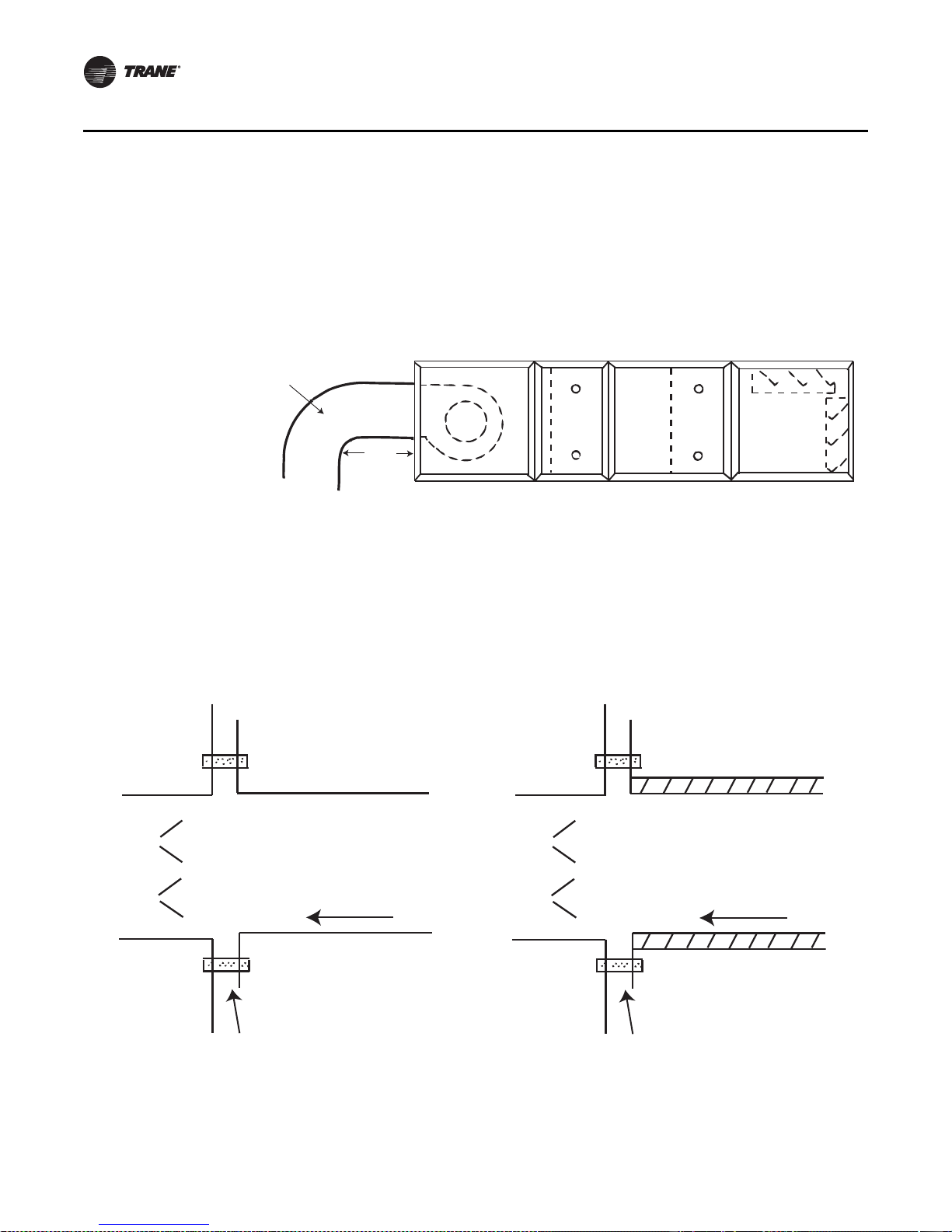
Component Installation Requirements
Unit
Section
Flat Connection
Uninsulated Duct
Airflow
Connections made directly to the discharge opening of a housed fan should have a minimum of
three fan diameters of straight duct before any turns or transitions. The ductwork should be the
same size as the fan discharge opening. The first turn of the connection should be in the same
direction as the fan rotation as shown in Figure 57. The air that the fan discharges into the duct is
extremely turbulent and requires some length of duct to stabilize. Abrupt changes in ductwork
directly off the fan discharge may adversely affect fan performance and acoustics.
Figure 57. Typical discharge ductwork recommendations
Splitters or
turning vanes
3 fan
Vane turns in same
direction as fan rotation
diameter
Damper Connections
minimum
For standard damper sections, size the at tached ductwork to fit the opening of the damper . The duct
opening dimensions should be in the unit submit tals. Ensure the insulation do es not obstruct the
damper opening when using a lined duct (see Figure 58 and Figure 59).
Figure 58. T ypical section with duc t flat/flange connection -
uninsulated or externally insulated
Figure 59. T ypical section with duct f lat/flange connection-
internally insulated
Insulated Duct
Unit
Section
Airflow
Flat Connection
72 CLCH-SVX07C-EN
Page 77

Component Installation Requirements
Bottom
supply/return
airflow
Trane AHU
base (typical)
Field-supplied
rigid duct
Trane AHU
base (typical)
Field-supplied
rigid duct
Bottom Opening Duct Installation
1. Install gasket to duct flange to ensure air tight seal.
2. Install duct into place underneath framed opening in unit base per Figure 60. Refer to factory
curb layout provided with unit submittals for duct size and location.
Figure 60. Field-supplied duct connection to AHU bottom supply/return air opening
3. Bottom of unit base elevation is flush with duct opening in bottom of unit (see Figure61 and
Figure 62).
CLCH-SVX07C-EN 73
Page 78

Component Installation Requirements
Field-supplied
duct
Gasket
Supply opening
in floor
Roof Curb
Unit
base
Unit
wall
Unit floor
Building roofing
and structure
may vary per job
Figure 61. Field-supplied duct connection details - curb mount
Figure 62. Field-supplied duct connection details - pier mount
Unit
Floor
Unit
Wall
Unit
Base
Building roong
and structure
may vary per job
Supply opening
in oor
Gasket
Field Supplied Duct
74 CLCH-SVX07C-EN
Page 79

Discharge Plenum Connections
Discharge plenum sections are available with or with out openings. Se ctions with rectangular and
round openings have a framed opening that can be used to secure the duct to the frames. If the duct
is lined, it is important the insulation does not obstruct the opening of the section.
For a discharge plenum with field-cut openings, attach the duct to the side panel.
Bellmouth Discharge Connections
Round duct connections to be fastened to plenum fan and discharge plenum sections with
bellmouth disc harge openings shoul d be siz ed to at tach to the casing or directly to the bellmouth
fitting. Attac hment to the casing requires the round duct diameter to be sized two inches larger than
the nominal bellmouth outlet. An angle ring with a flat flange should be af fixed to the roun d duct
to secure the duct to the casing (see Figure 63). Attachment to the bellmouth fitting requires the
duct and fitting to be insulated by the installing co ntractor u p to the b el lmou th radi us to preven t
condensation (see Figure 64). The bellmouth fitting extends through the casing by one inch.
Component Installation Requirements
Figure 63. Securing round duct to casing over
bellmouth outlet
Figure 64. Securing round duct t o bellm o uth outlet
CLCH-SVX07C-EN 75
Page 80

Component Installation Requirements
Traq damper
mixing box
Inlet duct
Traq damper
mixing box
Radius elbow
(sweep)
Mitered
corner
W
d
H
d = 1 hydraulic duct diameter = 2 x W x H
W + H
Traq Damper Connections
Size the duct connections to attac h to the specified por t ion on the face of the mixing box that the
duct connection completely covers all of the Traq damper.
For a mitered corner, provide one hydraulic duct diameter between the entering face of the Traq
dampers and the duct turn. For a radius e lbow, or sweep, pl ace the elbow directly ag ainst the face
of the Traq dampers (see Figure 65).
Figure 65. Traq damper duct connections
Exter nal Face-and-Bypass Connections
The external face-and-bypass damper sections will require a field-fabricated duct to direct the
bypass air into the appropriate section. Duct sizing recommendations are listed in Table 23.
Table 23. Recommended bypass duct sizes (inches)
Unit size H W L
3 162014
4 18 33 16
6 183316
8 18 39 16
10 18 50 16
12 22 55 20
14 22 61 20
17 22 61 20
21 28 69 26
25 28 69 26
30 28 82 26
35 45 80 36
40 45 93 36
50 45 106 36
57 47 106 40
66 48 121 40
80 56 121 48
100 56 135 48
120 56 162 48
76 CLCH-SVX07C-EN
Page 81

Component Installation Requirements
Fan
Coil
Coil
External
Face and Bypass
Duct
Access
When attac hing a bypass duct to a downstream fan section or access section, the section wi ll have
a factory-provided opening. (see Figure 66, Figure 67, and Figure 68.)
When bypassing into an access section, remove a panel. It is not necessary to cut an opening.
Figure 66. External face-and-bypass with duct configuration designed to bypass air into a
vertical f an section
Fan
Coil
Duct
External
Face and Bypass
Figure 67. External face-and-bypass with duct configuration designed to bypass air around one
coil
CLCH-SVX07C-EN 77
Page 82

Component Installation Requirements
Fan
Coil Coil
External
Face and Bypass
Duct
Unit Section
End of unit
2-inch panel
Thermal
break
Uninsulated Duct
2-inch panel
Thermal
break
Airflow
Unit Section
End of unit
2-inch panel
Thermal
break
Internally insulated Duct
2-inch panel
Thermal
break
Airflow
Figure 68. External face-and-bypass with duct configuration designed to bypass air into a
horizontal fan section
Other Connections
Access, filter, and other sections may have open inlets with a 2-inch (sizes 3-1 20) panel frame for
connecting the ductwork. If the duct is lined, it is important the insulation does not obstruct the
opening of the section.
Figure 69. Typical duct flat/flange end of unit connection -
uninsulated
Figure 70. Typical duct flat/flange end of unit connection -
insulated
78 CLCH-SVX07C-EN
Page 83

Coil Piping and Connections
General Recommendations
Proper installation, piping, and trappi ng is necessary to ensure satisfactory coil operation and to
prevent operational damage:
• Support all piping independently of the coils.
• Provide swing joints or flexible fit ti ngs on all connections that are adjacent to heating coils to
absorb thermal expansion and contraction strains.
• If the coil was ordered with factory-mounted controls, install the control valves. The valves ship
separately.
Note: The contractor is responsible for supplying the installation hardware.
• For best results, use a short pipe nipple on the coil headers prior to making any welded flange
or welded elbow type connections.
• Extended drain and vent connections are provided as standard on D1 and D2 coils only. If
extended drains and vents are required on other water coils, they must be field-installed or
ordered as specials from the factory.
• Pipe coils counterflow to airflow.
NOTICE:
Connection Leaks!
Use a backup wrench when attac h ing piping t o coils with copper headers to prevent damage to
the coil header. Do not use brass connectors because they distort easily and could cause
connection leaks.
• When attac hing the piping to the coil header , make the connection only tight enough to prevent
leaks. Maximum recommended torque is 200 foot-pounds.
NOTICE:
Over Tightening!
Do not use teflon-based products for any field connections because their high lubricity could
allow connections to be over-tightened, resulting in damage to the coil header.
• Use pipe sealer on all thread connections.
NOTICE:
Leakage!
Proper ly seal all penetrations in unit casing. Failure to seal penetrations from inner panel to
outer panel could result in unconditioned air entering the unit, and water infiltrating the
insulation, resulting in equipment damage.
• After completing the piping connections, seal around pipe from inner panel to outer panel.
CLCH-SVX07C-EN 79
Page 84

Coil Piping and Connections
H
J
L
Drain pan trapping for section
under negative pressure
L = H + J + pipe diameter where:
H = 1 inch for each inch of negative
pressure plus 1 inch
J = 1/2 H
Drain pan trapping for section
under positive pressure
L = H + J + pipe diameter where:
H = 1/2 inch (minimum)
J = 1/2 inch plus the unit positive static
pressure at coil discharge
(loaded filters)
Drain Pan Trapping
WARNING
No Step Surface!
Do not walk on the sheet metal dr ai n pan. Walking on the drain pan could cause the su pporting
metal to collapse. Failure of the drain pan could result in death or serious injury.
Threaded condensate drain connections are provided on only one side of the coil section. Pitch the
connection lines horizontal or downward toward an open drain. Trane recommends installing a
plug to facilitate cleaning of the trap. The drain connection sizes are:
Figure 71 illustrates the proper trapping, piping, and operation of the trap. Use the formula under
the figure to determine the correct minimum depth for the condensate trap. If a section has a drain
pan for cleaning purposes only , it does not need a trap; however , a cap or shutof f valve should be
installed on the drain connection. Only sections handling co ndensate, such as a cooling coil s ection
or moisture eliminator section, require a trap.
Unit size NPT (national pipe thread) external connection
3-30 1-inch
35-57 1 1/4 inch
66-120 1 1/2 inch
NOTICE:
Wa ter Damage!
When more than one section has a drain pain, trap each section individually. Connecting all
drains to a common line with only one trap could result in condensate retention and possible
water damage to the air handler or adjoining space.
Figure 71. Drain pan trapping for negative and positive pressure applications
80 CLCH-SVX07C-EN
Page 85

Steam Coil Piping
Air handlers fitted with steam coils have labeled holes for piping penetrations. Fi gure 72 illustrates
a typical steam coil piping configuration. S ee Table 24 for the codes of system components in these
figures.
The coil condensate return line must be piped f ull size of the condensate trap connection, except
for a short nipple screwed directly into the coil header’ s condensate return tapping. Do not b ush
or reduce the coil return trapping size.
Table 24. Code of system components for piping figures
Code System component
FT Float and thermostatic steam trap
GV Gate valve
OV Automatic two-position (ON-OFF) control valve
VB Vacuum breaker
ST Strainer
AV Automatic or manual air vent
MV Modulating control valve
Figure 72. Typical piping for Type NS steam coils and horizontal tubes for horizontal airflow
Coil Piping and Connections
Airflow
Pitch down
12 in. min.
Return main
Full size of
steam trap
connection
FT
FT
Steam main
ST
ST
VB
GV
VB
GV
Full
size
of
main
12 in. min.
MV
GV
ST
Full size of
coil connection
ST
FT
CLCH-SVX07C-EN 81
Page 86

Coil Piping and Connections
NOTICE:
Vacuum Breaker Cracking Pressure!
The 1/2-inch NPT, 15 degree swing check valve vacuum breaker is recommended because other
vacuum breakers, such as spring-loaded ball-check breakers, have cracking pressures as high as
1.25 inches Hg (1 7 inc hes of wat er). Vacuum break ers with fitting sizes smaller than 1/2 inch NPT
are too small to relieve vacuum quick enough to ensure complete condensat e dr ainage. Other
types of swing check valv e v acuum br eak ers ar e acceptable if the fittings size is not smaller than
1/2-inch NPT and the cracking pressure is not larger than 0.25 inches Hg (3.4 inches of water).
Failure to follow these instructions could result in equipment damage.
To prevent coil damage, complete the followin g recommendations:
• Install a 1/2-inch NPT, 15 degree swi ng check val ve vacuum breaker with cracking pressure of
0.25 inches Hg (3.4 inc hes water) or lower at the to p of the coil. This vacuum breaker should be
installed as close to the coil as possible.
• For coil type NS, install the vacuum breaker in the unused condensate return tapping at the top
of the coil.
• Vent the vacuum breaker line to atmosphere or connect it into the return main at the discharge
side of the steam trap
Note: V acuu m breaker relief is mandatory when the coil is controlled by a modulating steam
supply or automatic two position (ON-OFF) steam supply valve. Vacuum breaker relief is
also recommended when face-and-bypass control is used.
NOTICE:
Coil Condensate!
Condensate must flow freely from the coil at all times to prevent coil damage from water
hammer , unequal ther mal str esses, fr eeze-up and/or cor rosion. In all steam coil installations, th e
condensate return connections must be at the low point of the coil. Failure to follow these
instructions could result in equipment damage.
Proper steam trap installation is necessary for satisfactory coil performance and service life. For
steam trap installation:
1. Install the steam trap discharge 12 inches below the condensate return connection. Twelve
inches pro v ides sufficient hydrostatic head pressure to overcome trap losses and ensures
complete condensate removal.
a. Use float and thermostatic traps with atmospheric pressure gravity condensate return, with
automatic controls, or where the possibility of low-pressure supply steam exists. (Float and
thermostatic traps are recommended because of gravity drain and continuous discharge
operation.)
b. Use bucket traps only when the supply steam is not modulated and is 25 psig or higher.
Note: Trane steam coils require a minimum of 2 psi of pressure to assure even heat distribution.
2. Trap each coil separately to prevent holding up condensate in one or more of the coils.
3. Install strainers as close as possible to the inlet side of the trap.
4. If installing coils in series airflow, contro l each coil bank independently with an automatic
steam-control valve. Size the traps for each coil using the capacity of the first coil in direction
of airflow.
5. Use a modulating valve that has linear flow characteristics to obtain gradual modulation of the
coil steam supply.
Note: Do not modulate systems with overhead or pressurized returns unless the condensate is
drained by gravity into a receiver, vented to atmosphere, and returned to the condensate
pump.
82 CLCH-SVX07C-EN
Page 87

Coil Piping and Connections
AV
AV
AV
GV
Water supply
main
Water
return main
Drain
Air flow
Pitch down
6. Pitch all supply and return steam piping down 1 inch for every 10 feet in the direction of the
steam or condensate flow.
Note: Do not drain the steam mains or take-offs through the coils. Drain the mains ahead of the
coils through a steam trap to the return line.
7. Ensure overhead returns have 1 psig of pressure at the steam trap discharge for every 2 feet
of elevation for continuous condensate removal.
Water Coil Piping
Figure 73, and Figure 74 illustrate
typical water coil piping configurations.
T ype 5A, 5W, D1, W, UW , TT, P,2, P4, and
P8 water coils are self-venting only if
the water velocity exceeds 1.5 feet per
second (fps) in the coil tubes. Type D2,
UA, UU, and WD water coils are selfventing only if the water velocity
exceeds 2.5 fps in the coil tubes. See the
unit submittals for coil water velocity . If
the water velocity is below these
minimums, vent the coil by one of the
following methods:
1. Install an air vent in the top pipe
plug tapping of the return header.
2. When the return line rises above the
top of the coil, vent from the top of
the return header horizontally to the
return piping.
Note: TT coils are designed with larger
than normal end tube sheet
holes to allow for maximum
expansion. Air leakage around
tubes should be expected and
handled by capping over coil
ends or by sealing around tubes
with a pliable sealant such as
silicone.
Figure 73. Typical piping for type 5W one-row water coil
GV
GV
GV
Water supply
main
Water
return main
GV
Air flow
Level
AV
AV
Drain
Figure 74. Typical piping for type 5A, 5W two-row, W 3- to 12-row, WD, D1, and
D2 water coils
CLCH-SVX07C-EN 83
Page 88

Coil Piping and Connections
Pitch down
AV
AV
AV
Water
supply main
Water
return main
GV
Drain
Airflow
GV
MV
Figure 75. Typical piping for stacked water coils
84 CLCH-SVX07C-EN
Page 89

Refrigerant Coil Piping
Discharge
line
Manual
ball valve
Access
port
Filter
Access
port
Access
port
Filter drier
with access
port
Manual
angle valves
Check/relief
valve
Condensing unit
Condenser and
sbucooler coil
Compressors
Liquid line
Access
port
Manual
ball valve
Solenoid
valve
Moisture-
indicating
sight glass
Expansion
valves
Evaporator coil
Distriburtor
Manual ball valve
Suction lineFrostat™ control
Manual
ball valve
Kit with sensor - X13790452010 SEN-01212
Kit with switch - X13100429010 THT 02442
Note: Refer to for information on handling refrigerants.
Use Figure 76 to determine the proper, relative sequence of the components in the refrigerant lines
that connect the condensing unit to an evaporator coil. Refer to “Examples of Field-Installed
Evaporator Piping” on page 89 for more detailed schematics of evaporator piping.
Figure 76. Example of placement for split-system components
Coil Piping and Connections
CLCH-SVX07C-EN 85
Page 90

Coil Piping and Connections
Liquid Lines
Line Sizing
Properly sizing the liquid line is critical to a successful split-system application. The selected tube
diameter must provide at least 5°F [2.7°C] of subcooling at the expansion valve throughout the
operating envelope. Increasing the siz e of the liquid line will not increase the available subcooling.
Routing. Install th e liquid line with a slight slope in the direction of flow so t hat it can be routed with
the suction line. Minimize tube bends and reducers because these items tend to increase pressure
drop and to reduce subcooling at the expansion valve. Liquid line receivers, other than those that
are factory-installed, are not recommended.
Insulation
The liquid line is generally warmer than the surrounding air, so it does not require insulation. In
fact, heat loss from the liquid line improves system capacity because it provides additional
subcooling.
Components
Liquid-line refrigerant components necessary for a successful job include a filter drier , access port,
solenoid valve, moisture-indicating sight glass, expansion valve(s), and ball shutoff valves.
Figure 76 illustrates the proper sequence for positioning them in the liquid line. Position the
components as close to the evaporator as possible.
• Filter drier. There is no substitute for cleanliness during system installation. The filter drier
prevents residual contaminants, introduced during installation, from entering the expansion
valve and solenoid valve.
• Access port. The access port allows the unit to be charged with liquid refrigerant and is used
to determine subcooling. This port is usually a Schraeder
• Solenoid valve. In split systems, solenoid valves isolate the refrigerant from the evaporator
during off cycles; under cer tain conditions, they may also trim the amount of active evaporator
as compressors unload. Generally, the “trim” solenoid valve is unnecessary for variable-airvolume comfort-cooling applications, and is only required for constant-volume applications
when dehumidification is a concern.
• Moisture-indicating sight glass. Be sure to install one moisture-indicating sight glass in the
main liquid line. The only value of the sight glass is its moisture indication ability. Use actual
measurements of temperature and pressure—not the sight glass—to determine subcooling
and whether the system is properly charged. The moisture indi cator/sight glass must be sized
to match the size of the liquid line at the thermal expansion valve.
®
valve with a core.
86 CLCH-SVX07C-EN
Page 91

• Thermal expansion valve. The expansion valve is the throttling device that meters the
Cut here
for piping
Perforated plate
(packed elbow)
Panel
Venturi type
distributor
Coil
refrigerant into the evaporator coil. Metering too much refrigerant floods the compressor;
metering too little elevates the compressor temperature. Choosing the correct size and type of
expansion valve is critical to assure it will correctly meter refrigerant into the evaporator coil
throughout the entire operating envelope of the system. Correct refrigerant distribution into the
coil requires an expansion valve for each distributor.
NOTICE:
Valve Damage!
Disassemble the thermal expansion valve before completing the brazing connections. If
necessary, wrap the valve in a cool, wet cloth while brazing. Failure to protect the valve from
high temperatures could result in damage to internal components.
Figure 77. Type F refrigerant coil with packed elbow
Coil Piping and Connections
The thermal expansion valve must be selected
for proper size and capacity. The size of the
expansion valve should cover the full range of
loadings. Check that the valve will successfully
operate at the lightest load condition. For
improved modulation, choose expansion
valves with balanced port construction and
external equalization.
Cut the process tube and cap assembly from the
liquid connection as shown in Figure 77 and
install the expansion valve directly to the liquid
connections.
Suction Lines
Line sizing
Proper suction-line sizing is required to guarantee the oil returns to the compressor throughout the
system’s operating envelope. At the same time, the line must be sized so that the pressure drop
does not excessively affect capacity or efficiency. To accomplish both objectives, it may be
necessary to use two different line diameters: one for the horizontal run and for ver tical drops, and
another for the vertical lifts.
Routing
To prevent residual or condensed refrigerant from “free-flowing” toward the compressor, install
the suction line so it slopes slightly—that is, by ¼ inch to 1 inch per 10 feet of run—toward the
CLCH-SVX07C-EN 87
evaporator. When the application includes a suction riser, oil must be forced to travel the height
of the riser. Riser traps and double risers are unnecessary in the suction line when the refrigerant
coil is used with Trane condensing units.
Avoid putting refrigerant lines underground. Refrigerant condensation or installation debris inside
the line, service access, and abrasion/corrosion can quickly impair reliability.
Insulation
Any heat that transfers from the surrounding air to the cooler suction lines increases the load on
the condenser (reducing the system’s air-conditioning capacity) and promotes condensate
Page 92

Coil Piping and Connections
formation (adversely affecting indoor air quality). Af ter operating the system and testing all fittings
and joints to verify the system is leak-free, insulate the suction lines all the way to inner side panel
to prevent heat gain and unwanted condensation.
Components
Installing the suction line requires field installa tion of these components: a filter , access port , and
a Frostat™ control when the refrigerant coil is used with T rane condensing uni ts. Position them as
close to the compressor as possible.
Note: Placement of the Frostat control is illustrated in Figure 76 on page 85.
• Filter. The suction filter prevents contaminants, introduced during installation, from entering
the compressor. For this reason, the suction filter should be the replaceable-core type, and a
clean core should be installed after the system is cleaned up.
• Access port. The access port is used to determine suction pressure. This port is usually a
Schraeder valve with a core.
• Frostat™ coil frost protection. The Frostat control is the preferred method for protecting
evaporator coils from freezing when the refrigerant coil is used with Tr an e condensing units.
It senses the suction-line temperature and temporarily disables mec hanical cooling if it detects
frost conditions. The control is mec hanically attac hed to the outside of the refrigerant line, near
the evaporator, and wired to the unit control panel.
• Ball shutoff valve. Adding manual, ball-type shutoff valves upstream and downstream of the
filter simplifies replacement of the filter core.
88 CLCH-SVX07C-EN
Page 93

Examples of Field-Installed Evaporator Piping
Single-Circuit Condensing Unit: Evaporator Coil with One Distributor
Figure 78. Single-circuit evaporator coil with one distributor
Coil Piping and Connections
1. Pitch the liquid line slightly—1inch/10feet —so that the refrigerant drains toward the
evaporator.
2. Provide one expansion valve per distributor.
3. Slightly pitch the outlet line from the suction header toward the suction riser—that is, 1 inch/
10 feet in the di rection of flow. Use the tube diameter that matches the suction-header
connection.
4. For the vertical riser, use the tube diameter recommended by the condensing unit
manufacturer. Assure the top of the riser is higher than the evaporator coil.
5. Arrange the suction line so the refrigerant gas leaving the coil flows down ward, past the lowest
suction-header outlet, before turning upward.
6. Pitch the suction l ine slightly—1 in ch/1 0feet —so the refrigerant drains toward the evaporator.
7. Insulate the suction line.
CLCH-SVX07C-EN 89
Page 94

Suction line
7, 8
Liquid
line
Evaporator coil
with horizontal-split
(standard) circuiting
Evaporator coil with
intertwined circuiting
Liquid
line
‘Trim’
solenoid valve
‘Pump-down’
solenoid valve
Sight
glass
1
Filter drier
Filter drier
Solenoid
valve
Thermal
expansion
valve (TXV)
9
2
2
1
9
7, 8
3
4
4
5
5
6
6
3
3
Distributor
Thermal
expansion
valve (TXV)
Sight
glass
Distributor
S
S
S
Coil Piping and Connections
Single-Circuit Condensing Unit: Evaporator Coil with Two Distributors
Figure 79. Single-circuit evaporator coil with two distributors 1. Pitch the liquid line slightly—1 inch/10 feet
—so the refrigerant drains toward the
evaporator.
2. Provide one expansion valve per distributor.
3. Slightly pitch the outlet line from the suction
header toward the suction riser—that is,
1 inch/10 feet in the direction of flow. Use
the tube diameter that matches the suctionheader connection.
4. Arrange the suction line so the refrigerant
gas leaving the coil flows downward, past
the lowest suction-header outlet, before
turning upward. Use a double-elbow
configuration to isolate the thermal
expansion valve bulb from other suction
headers.
5. For horizontal tubing, use the tube diameter
recommended by the condensing unit
manufacturer.
6. For the vertical riser , use the tube diameter
recommended by the condensing unit
manufacturer. Assure the top of the riser is
higher than the evaporator coil.
7 . Pitch the suction line slightly—1 inc h/10 feet
—so the refrigerant drains toward the
evaporator.
8. Insulate the suction line.
9. Only use a “trim” solenoid valve for
constant-volume, humidity-sensitive
applications. For all other applications,
install a single solenoid valve (the
“pumpdown” solenoid valve) between the
liquid-line filter drier and the sight glass.
90 CLCH-SVX07C-EN
Page 95

Coil Piping and Connections
Single-Circuit Condensing Unit: Evaporator Coil with Four Distributors
Figure 80. Single-circuit evaporator coil with four distributors 1. Pitch the liquid line slightly—1 inch/
10 feet —so the refrigerant drains
toward the evaporator.
2. Provide one expansion valve per
distributor.
3. Slightly pitch the outlet line from the
suction header toward the suction
riser—that is, 1 inch/10 feet in the
direction of flow. Use the tube diameter
that matches the suction-header
connection.
4. Arrange the suction line so the
refrigerant gas leaving the coil flows
downward, past the lowest suctionheader outlet, before turning upward.
Use a double-elbow configuration to
isolate the thermal expansion valve
bulb from other suction headers.
5. For horizontal tubing, use the tube
diameter recommended by the
condensing unit manufacturer.
6. For the vertical riser, use the tube
diameter recommended by the
condensing unit manufacturer. Assure
the top of the riser is higher than the
evaporator coil.
7. Pitch the suction line slightly—1 inch/
10 feet —so the refrigerant drains
toward the evaporator.
8. Insulate the suction line.
9. Only use a “trim” solenoid valve for
constant-volume, humidity-sensitive
applications. For all other applications,
install a single solenoid valve (the
“pumpdown” solenoid valve) between
the liquid-line filter drier and the sight
glass.
CLCH-SVX07C-EN 91
Page 96

Coil Piping and Connections
Dual-Circuit Condensing Unit: Evaporator Coil with Two Distributors)
Figure 81. Dual-circuit evaporator coil with two distributors
1 . Pitch the liquid lines slightly—1 inch/1 0 feet —so the refrigerant drains toward the evaporator.
2. Provide one expansion valve per distributor.
3. Slightly pitch the outlet line from the suction header toward the suction riser—that is, 1 inch/
10 feet in the di rection of flow. Use the tube diameter that matches the suction-header
connection.
4. The top of the Circuit 1 suction riser must be higher than the bottom evaporator coil. Use the
tube diameter recommended by the condensing unit manufacturer for the riser.
5. Arrange the suction line so the refrigerant gas leaving the coil flows downward, past the lowest
suction-header outlet, before turning upward.
6. The top of the Circuit 2 suction riser must be higher than the top evaporator coil. Use the tube
diameter recommended by the condensing unit manufacturer for the riser.
7. Pitch the suction lines slightly—1 inc h/10feet —so the refrigerant drains toward the evaporator.
8. Insulate the suction lines.
92 CLCH-SVX07C-EN
Page 97

Coil Piping and Connections
Dual-Circuit Condensing Unit: Evaporator Coil with Four Distributors
Figure 82. Dual-circuit evaporator coil with four distributors 1. Pitch the liquid line slightly—1inch/10feet
—so the refrigerant drains toward the
evaporator.
2. Provide one expansion valve per
distributor.
3. Slightly pitch the outlet line from the
suction header toward the suction
riser—that is, 1 inc h/1 0 feet in the direction
of flow. Use the tube diameter that ma tches
the suction-header connection.
4. Arrange the suction line so the refrigerant
gas leaving the coil flows downward, past
the lowest suction-header outlet, before
turning upward. Use a double-elbow
configuration to isolate the thermal
expansion valve bulb from other suction
headers.
5. For horizontal tubing, use the tube diameter
recommended by the condensing unit
manufacturer.
6. For the vertical riser , use the tube diameter
recommended by the condensing unit
manufacturer. Assure the top of the riser is
higher than the evaporator coil.
7. Pitch the suction line slightly—1inch/
10 feet —so the refrigerant drains toward
the evaporator.
8. Insulate the suction line.
9. The top of the Circuit 1 suction riser must be
higher than the bottom evaporator coil. Use
the tube diameter recommended by the
condensing unit manufacturer for the riser.
10. The top of the Circuit 2 suction riser must be
higher than the top evaporator coil. Use the
tube diameter recommended by the
condensing unit manufacturer for the riser.
CLCH-SVX07C-EN 93
Page 98

Coil Piping and Connections
Dual-Circuit Condensing Unit: Evaporator Coil with Eight Distributors
Figure 83. Dual-circuit evaporator coil with eight distributors
1 . Pitch the liquid l ine slightly—1 inc h/10 feet
—so the refrigerant drains toward the
evaporator.
2. Provide one expansion valve per
distributor.
3. Slightly pitch the outlet line from the
suction header toward the suction
riser—that is, 1 inc h/10 feet in the direction
of flow. Use the tube diameter that
matches the suction-header connection.
4. Arrange the suction line so the refrigerant
gas leaving the coil flows downward, past
the lowest suction-header outlet, before
turning upward. Use a double-elbow
configuration to isolate the TXV bulb from
other suction headers.
5. For horizontal tubing, use the tube
diameter recommended by the
condensing unit manufacturer.
6. For the vertical riser , use the tube diameter
recommended by the condensing unit
manufacturer. Assure the top of the riser is
higher than the evaporator coil.
7. Pitch the suction line slightly—1 inch/
10 feet —so the refrigerant drains toward
the evaporator.
8. Insulate the suction line.
9. The top of the Circuit 1 suction riser must
be higher than the bottom evaporator coil.
Use the tube diameter recommended by
the condensing unit manufacturer for the
riser.
10. The top of the Circuit 2 suction riser must
be higher than the top evaporator coil. Use
the tube diameter recommended by the
condensing unit manufacturer for the
riser.
11. Only use a “trim” solenoid valve for
constant-volume, humidity-sensitive
applications. For all other applications,
install a single solenoid valve (the
“pumpdown” solenoid valve) between the
liquid-line filter drier and the sight glass.
94 CLCH-SVX07C-EN
Page 99

Installation - Electrical
WARNING
Hazardous Voltage w/ Capacitors!
Disconnect all electric power, including remote disconnects before servicing. Follow proper
lockout/tagout procedures to ensure the equipment cannot be inadvertently energized. For
variable frequency drives or other energy storing components provided by Trane or others, refer
to the appropriate manufacturer’s literature for allowable waiting periods for discharge of
capacitors. Verify with an appropriate voltmeter that all capacitors have discharged. Failure to
disconnect power and discharge capacitors before servicing could result in death or serious
injury.
Note: For additional information regarding the safe discharge of capacitors, see
PROD-SVB06A-EN or PROD-SVB06A-FR
WARNING
Proper Field Wiring and Grounding Required!
All field wiring MUST be performed by qualified personnel. Improperly installed and grounded
field wiring poses FIRE and ELECTRO CUTION hazar ds. To avoid these hazards, you MUST f ollo w
requirements for field wiring installation and grounding as described in NEC and your local/
state electrical codes. Failure to follow codes could result in death or serious injury.
Use Copper Conductors Only!
Unit terminals are not designed to accept other types of conductors. Use of aluminum or other
type of wiring may result in galvanic corrosion or overheating. Failure to use copper conductors
could result in equipment damage.
If the unit does not include a factory-mounted star ter, wiring to the unit fan motor must be provided
by the installer and must comply with all national and local electrical codes. The installer must also
furnish a service disconnect switch in compliance with national and local electrical codes.
Fan motors require motor overload protective devices that are rated or selected in compliance with
the National Electric Code (NEC) or Canadian Electric Code. Specific unit and motor connection
diagrams are provided on the starter/VFD if Trane-provided, or refer to the motor nameplate.
If wiring directly to the motor, a flexible connection at the motor to permit fan belt adjustment
should be provided. Fractional horsepower motors may be factory connected to a terminal box on
the unit. If this construction is provided, the in staller should complete field wiring to this connection
box. For a typical high voltage wiring schematic, see Figure 84.
CLCH-SVX07C-EN 95
Page 100

Installation - Electrical
Figure 84. Typical VFD wiring schematic
96 CLCH-SVX07C-EN
 Loading...