

Page 1
Modular
Multi-position
Air Handlers
GAT2A0B42S31SA
GAT2A0C48S41SA
GAT2A0C60S51SA
PUB. NO. 22-1857-03
Page 2

Features
and Benefits
• Unique Cabinet Design
- Double Wall Foamed and Formed
Cabinet System
- Water Proof Cabinet Design
- R-4.2 Insulating Value (Avg. Insulating
Value R-8.2)
- Composite Foamed Cabinet Doors
- Sweat Eliminating Cabinet Design
- Loose Fiber Eliminating Cabinet
Design
- Smooth Cleanable Cabinet Design
- 2% or Less air leakage
- Precision Applied Durable Door Seals
- Tool-free Fasteners on Blower/Filter
Door
- Modular Cabinet
• Multi-Position Upflow/ Horizontal Left
/ Horizontal Right
• Braze in Refrigerant Connection
• Primary/Secondary Condensate
Connections
• Premarked Conduit Connection
Locations
• Vortica Blower with Integrated Slide
Deck for Easy Removal
• Polarized Plug connections on
Blower
• Control Protection Pocket
• Aluminum Coil with Integrated Slide
Deck for Easy Removal
• Slide in Electric Heaters
• Polarized Plug connections for
Electric Heater
• Labeled Panels and connections
• 1-1/4" to 1" And 3/4" to 1/2" Conduit
connection on Left, Right and Top
• Molded in 1" Standard Filter rail
• R-410A Thermal Expansion Valve
(TXV)
• Low Voltage Terminal Connection
Point
• Enhanced Coil Fin Patented
• Blow Through Design
• PSC 3 Speed Motor on 3.5 & 4 ton
models
• Constant torque ECM Motor on 5 ton
model
• Maximum Width of 23.5"
• Compact 20.8" depth with doors
removed
• Integrated Horizontal Drain pans
• Single Color
• Fused 24V Power
• Safety Door Switch
• 5 year warranty
• 10-year warranty registered
• Optional extended warranty
available
© 2012 Trane
2 Pub. No. 22-1857-03
Page 3

Contents
Features and Benefits 2
Optional Equipment 4
Unique Cabinet Design Features and Benets 5
General Data 6
GAT2A0B42S31SA 6
GAT2A0C48S41SA 6
GAT2A0C60S51SA 6
Performance Data 7
Electrical Data 10
Wiring Diagrams 13
Field Wiring 15
Convertibility 17
Dimensions 18
Pub. No. 22-1857-03 3
Page 4
Optional Equipment
OPTIONAL EQUIPMENT FOR AIR HANDLERS
Accessory Number Description Fits Cabinet Size
BAYEAAC05BK1A Electric Heater, 5kW, Breaker, 24V Control, 1 Ph A to C
BAYEAAC05LG1A Electric Heater, 5kW, Lugs, 24V Control, 1 Ph A to C
BAYEAAC08BK1A Electric Heater, 8kW, Breaker, 24V Control, 1 Ph A to C
BAYEAAC08LG1A Electric Heater, 8kW, Lugs, 24V Control, 1 Ph A to C
BAYEAAC10BK1A Electric Heater, 10kW, Breaker, 24V Control, 1 Ph A to C
BAYEAAC10LG1A Electric Heater, 10kW, Lugs, 24V Control, 1 Ph A to C
BAYEABC15BK1A Electric Heater, 15kW, Breaker, 24V Control, 1 Ph B to C
BAYEABC20BK1A Electric Heater, 20kW, Breaker, 24V Control, 1 Ph B to C
BAYEACC25BK1A Electric Heater, 25kW, Breaker, 24V Control, 1 Ph C
BAYSUPFLGBA Supply Duct Flange B B
BAYSUPFLGCA Supply Duct Flange C C
BAYRETFLGB Return Duct Flange B B
BAYRETFLGCA Return Duct Flange C C
TASB215SB Plenum Stand B with integrated sound baffle B
TASB235SB Plenum Stand C with integrated sound baffle C
BAYSRKIT100A Side Return Kit A to C
BAYICSKIT01A Internal Condensate Switch Kit A to C
BAYHHKIT001A Horizontal Hanger Kit A to C
BAYUVCLK001A UVC Lights A to C
BAYLVKIT100A Low Voltage Conduit Entry Kit A to C
4 Pub. No. 22-1857-03
Page 5
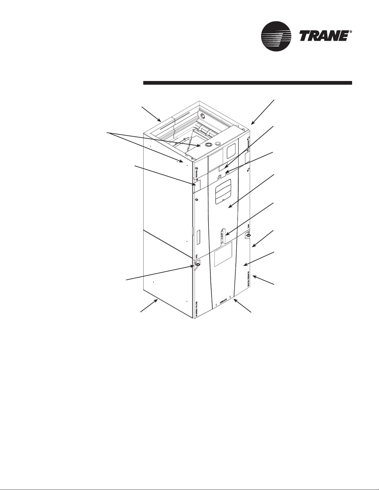
Unique Cabinet
Design Features and Benefits
1 Unique Cabinet Design
5 Conduit
Connections
e Integrated Horizontal
Drain Pans
2 Precision Durable
Door Seals
0 Thermal Expansion
Valve (TXV)
3 Refrigeration
Connections
8 All Aluminum Coil
4 Condensate
Connections
r Safety Door Switch
7 VorticaTM Blower
and Deck
6 Tool-less Door
Fasteners
w Compact 20.8” Depth
with Doors Removed
1 Unique Cabinet Design
- Double wall foamed cabinet system
- Waterproof Cabinet Design
- R-4.2 Insulating Value (Avg Insulating Value R-8.2)
- Composite Foamed Cabinet Doors
- Sweat Eliminating Cabinet Design
- Loose Fiber Eliminating Design
- Smooth Cleanable Cabinet Design
2 Precision Durable Door Seals
3 Refrigeration Connections
4 Condensate Connections
5 Conduit Connections - Conduit Connections on Left,
Right, and Top
6 Tool-less Door Fasteners
7 VorticaTM Blower and Deck - Polarized Plug on Blower
9 Labeled Panels
and Connections
q Maximum width
is 23.5”
8 All Aluminum Coil
- Integrated Slide Deck for Easy Removal
- Polarized Plug connections on Coil EEV
- Patented Enhanced Coil Fin
9 Labeled Panels and Connections
0 R-410A Thermal Expansion Valve (TXV)
q Maximum width is 23.5”
w Compact 20.8” Depth with Doors Removed
e Integrated Horizontal Drain Pans
r Safety Door Switch - Fused 24V Power
t Modular Cabinet
Pub. No. 22-1857-03 5
Page 6

General
Data
MODEL
RATED VOLTS/PH/HZ.
RATINGS 1
INDOOR COIL — Type
Rows — F.P.I.
Face Area (sq. ft.)
Tube Size (in.)
Refrigerant Control
Drain Conn. Size (in.) 2
DUCT CONNECTIONS
INDOOR FAN — Type
Diameter-Width (In.)
No. Used
Drive - No. Speeds
CFM vs. in. w.g.
No. Motors — H.P.
Motor Speed RPM
Volts/Ph/Hz
F.L. Amps - L.R. Amps
FILTER
Filter Furnished?
Type Recommended
No.-Size-Thickness
REFRIGERANT
Ref. Line Connections
Coupling or Conn. Size — in. Gas
Coupling or Conn. Size — in. Liq.
DIMENSIONS
Crated (In.)
Uncrated
WEIGHT
Shipping (Lbs.) / Net (Lbs.)
GAT2A0B42S31SA
PRODUCT SPECIFICATIONS
208-230/1/60
See O.D. Specifications
Plate Fin
3 - 14
5.04
3/8
TXV
3/4 NPT
See Outline Drawing
Centrifugal
10 X 10
1
Direct - 3
See Fan Performance Table
1 - 1/2
1075
208-230/1/60
2.7 - 5.0
No
Throwaway
1 - 20 X 20 - 1 in.
R-410A
Brazed
7/8
3/8
H x W x D
56.8 x 23.5 x 24.5
55.7 x 21.3 x 21.8
144/133
GAT2A0C48S41SA
208-230/1/60
See O.D. Specifications
Plate Fin
3 - 14
5.50
3/8
TXV
3/4 NPT
See Outline Drawing
Centrifugal
11 X 10
1
Direct - 3
See Fan Performance Table
1 - 1/2
1075
208-230/1/60
3.1 - 5.5
No
Throwaway
1 - 20 X 22 - 1 in.
R-410A
Brazed
7/8
3/8
H x W x D
58 x 25.5 x 24.5
56.9 x 23.5 x 21.8
155/143
GAT2A0C60S51SA
208-230/1/60
See O.D. Specifications
Plate Fin
4 - 14
5.50
3/8
TXV
3/4 NPT
See Outline Drawing
Centrifugal
11 X 10
1
Direct - 5 3
See Fan Performance Table
1 - 1
1050
208-230/1/60
7.6 - n/a
No
Throwaway
1 - 20 X 22 - 1 in.
R-410A
Brazed
7/8
3/8
H x W x D
62.8 x 25.5 x 24.5
61.7 x 23.5 x 21.8
171/159
1 These Air Handlers are AHRI certified with various Split System Air Conditioners
and Heat Pumps (AHRI STANDARD 210/240). Refer to the Split System Outdoor
Unit Product Data Guides for performance data.
2 3/4" Male Plastic Pipe (Ref.: ASTM 1785-76)
3 Constant torque Motor
6 Pub. No. 22-1857-03
Page 7

General
Data
GAT2A0B42 AIRFLOW PERFORMANCE TABLE
AIRFLOW PERFORMANCE
GAT2A0B42S31SA
EXTERNAL STATIC
(in w.g)
Speed Taps - 230 VOLTS Speed Taps - 208 VOLTS
3 2 † 1 3 2 † 1
0 1646 1495 1358 1522 1298 1138
0.1 1599 1464 1335 1489 1285 1137
0.2 1546 1421 1313 1449 1260 1120
0.3 1488 1380 1280 1401 1233 1099
0.4 1425 1329 1233 1348 1193 1065
0.5 1353 1264 1178 1281 1140 1023
0.6 1259 1182 1108 1202 1075 958
0.7 1145 1081 995 1102 965 868
0.8 982 909 839 926 817 753
0.9 788 759 731 761 713 N/A
1.0 563 N/A N/A 538 N/A N/A
NOTES:
1. Values are with wet coil and without filters.
2. Contact your particular filter manufacturer for pressure drop data.
3. Electric heater pressure drop is negligible and is included within the airflow data.
4. † Factory Setting
AIRFLOW (CFM)
GAT2A0B42S31SA MINIMUM HEATER AIRFLOW CFM
Heater Minimum Air Speed Tap
With Heat Pump Without Heat Pump
BAYEAAC05BK1AA
BAYEAAC05LG1AA
BAYEAAC08BK1AA
BAYEAAC08LG1AA
BAYEAAC10BK1AA
BAYEAAC10LG1AA
BAYEABC15BK1AA Tap 1 Tap 1
BAYEABC20BK1AA Tap 3 Tap 1
SEE AIR HANDLER NAMEPLATE FOR ADDITIONAL INFORMATION
Pub. No. 22-1857-03 7
Tap 1 Tap 1
Tap 1 Tap 1
Tap 1 Tap 1
Note: Heating and cooling
speeds are the same, factory
set at Speed Tap #2.
Page 8

Performance
Data
GAT2A0C48 AIRFLOW PERFORMANCE TABLE
AIRFLOW PERFORMANCE
GAT2A0C48S41SA
EXTERNAL STATIC
(in w.g)
Speed Taps - 230 VOLTS Speed Taps - 208 VOLTS
3 2 † 1 3 2 † 1
0 1904 1711 1541 1652 1455 1305
0.1 1881 1687 1529 1640 1450 1288
0.2 1844 1666 1511 1619 1425 1271
0.3 1806 1637 1485 1592 1410 1249
0.4 1766 1602 1454 1559 1381 1231
0.5 1716 1560 1420 1524 1351 1198
0.6 1659 1513 1380 1484 1321 1165
0.7 1594 1458 1333 1434 1283 1127
0.8 1525 1395 1277 1376 1229 1067
0.9 1442 1310 1194 1304 1149 N/A
1.0 1345 N/A N/A 1194 N/A N/A
NOTES:
1. Values are with wet coil and without filters.
2. Contact your particular filter manufacturer for pressure drop data.
3. Electric heater pressure drop is negligible and is included within the airflow data.
4. † Factory Setting
AIRFLOW (CFM)
GAT2A0C48S41SA MINIMUM HEATER AIRFLOW CFM
Heater Minimum Air Speed Tap
With Heat Pump Without Heat Pump
BAYEAAC05BK1AA
BAYEAAC05LG1AA
BAYEAAC08BK1AA
BAYEAAC08LG1AA
BAYEAAC10BK1AA
BAYEAAC10LG1AA
BAYEABC15BK1AA Tap 1 Tap 1
BAYEABC20BK1AA Tap 1 Tap 1
BAYEACC25BK1AA Tap 3
1 Not qualified for 208 V
SEE AIR HANDLER NAMEPLATE FOR ADDITIONAL INFORMATION
8 Pub. No. 22-1857-03
Tap 1 Tap 1
Tap 1 Tap 1
Tap 1 Tap 1
Tap 2 1
Note: Heating and cooling
speeds are the same, factory
set at Speed Tap #2.
Page 9

Performance
Data
GAT2A0C60 AIRFLOW PERFORMANCE TABLE
AIRFLOW PERFORMANCE
GAT2A0C60S51SA
EXTERNAL STATIC
(in w.g)
Speed Taps - 230 VOLTS Speed Taps - 208 VOLTS
5 4 † 3 2 1 5 4 † 3 2 1
0 2169 1956 1874 1739 1633 2165 2033 1871 1736 1629
0.1 2161 1916 1839 1696 1588 2155 1990 1833 1690 1582
0.2 2130 1889 1803 1667 1554 2121 1961 1795 1659 1545
0.3 2102 1850 1774 1628 1523 2090 1919 1763 1617 1511
0.4 2066 1818 1741 1596 1491 2052 1884 1727 1582 1477
0.5 2015 1785 1707 1564 1457 1998 1848 1690 1547 1440
0.6 1959 1754 1673 1520 1408 1939 1814 1653 1500 1389
0.7 1888 1716 1638 1477 1372 1880 1774 1615 1455 1349
0.8 1811 1680 1605 1440 1323 1820 1735 1580 1415 1298
0.9 1750 1628 1561 1403 1291 1770 1680 1533 1376 1263
1.0 1680 1604 1533 1368 1256 1725 1654 1503 1337 1226
NOTES:
1. Values are with wet coil and without filters.
2. Contact your particular filter manufacturer for pressure drop data.
3. Electric heater pressure drop is negligible and is included within the airflow data.
4. † Factory Setting
AIRFLOW (CFM)
GAT2A0C60S51SA MINIMUM HEATER AIRFLOW CFM
Heater Minimum Air Speed Tap
With Heat Pump Without Heat Pump
BAYEAAC05BK1AA
BAYEAAC05LG1AA
BAYEAAC08BK1AA
BAYEAAC08LG1AA
BAYEAAC10BK1AA
BAYEAAC10LG1AA
BAYEABC15BK1AA Tap 4 Tap 3
BAYEABC20BK1AA Tap 4 Tap 3
BAYEACC25BK1AA Tap 5 Tap 4
SEE AIR HANDLER NAMEPLATE FOR ADDITIONAL INFORMATION
Pub. No. 22-1857-03 9
Tap 2 Tap 2
Tap 3 Tap 2
Tap 3 Tap 2
Note: Heating and cooling
speeds are the same, factory
set at Speed Tap #4 for the
CTM motor.
Page 10

Performance
Data
WIRING DATA
GAT2A0B42S31SA
240 VOLT 208 VOLT
Heater
Model
No.
No Heater - - - 2.7** 3 15 - - 2.7** 3 15
BAYEAAC05++ 1 4.80 16400 20 28 30 3.60 12300 17.3 25 25
BAYEAAC08++ 1 7.68 26200 32 43 45 5.76 19700 27.7 38 40
BAYEAAC10++ 1 9.60 32800 40 53 60 7.20 24600 34.6 47 50
BAYEABC15++
circuit 1 9.60 32800 40 53 60 7.20 24600 34.6 47 50
circuit 2 4.80 16400 20 25 25 3.60 12300 17.3 22 25
No.
of
Circuits
Capacity
kW BTUH kW BTUH
Heater
Amps
per
Circuit
Minimum
Circuit
Ampacity
Maximum
Overload
Protection
Capacity
Heater
Amps
per
Circuit
Minimum
Circuit
Ampacity
Maximum
Overload
Protection
BAYEABC20++
circuit 1 9.60 32800 40 53 60 7.20 24600 34.6 53 60
circuit 2 9.60 32800 40 50 50 7.20 24600 34.6 43 45
Note: ** Motor Amps
10 Pub. No. 22-1857-03
Page 11

Performance
Data
WIRING DATA
GAT2A0C48S41SA
240 VOLT 208 VOLT
Heater
Model
No.
No Heater - - - 3.1** 4 15 - - 3.1** 4 15
BAYEAAC05++ 1 4.80 16400 20.0 29 30 3.60 12300 17.3 26 30
BAYEAAC08++ 1 7.68 26200 32.0 44 45 5.76 19700 27.7 38 40
BAYEAAC10++ 1 9.60 32800 40.0 54 60 7.20 24600 34.6 47 50
BAYEABC15++
circuit 1 9.60 32800 40.0 54 60 7.20 24600 34.6 47 50
circuit 2 4.80 16400 20.0 25 25 3.60 12300 17.3 22 25
No.
of
Circuits
Capacity
kW BTUH kW BTUH
Heater
Amps
per
Circuit
Minimum
Circuit
Ampacity
Maximum
Overload
Protection
Capacity
Heater
Amps
per
Circuit
Minimum
Circuit
Ampacity
Maximum
Overload
Protection
BAYEABC20++
circuit 1 9.60 32800 40.0 54 60 7.20 24600 34.6 53 60
circuit 2 9.60 32800 40.0 50 50 7.20 24600 34.6 43 45
BAYEABC25++ 1
circuit 1 9.60 32800 40.0 54 60 7.20 24600 34.6 47 50
circuit 2 9.60 32800 40.0 50 50 7.20 24600 34.6 43 45
circuit 3 4.80 16400 20.0 25 25 3.60 12300 17.3 22 25
Note: ** Motor Amps
1 Not qualified for 208 V without Heat Pump
Pub. No. 22-1857-03 11
Page 12

Performance
WHEEL
BLOWER HOUSING
BELLY BAND
MOTOR
A
A is determined per chart
Wheel is centered in
Blower Housing
Data
WIRING DATA
GAT2A0C60S51SA
240 VOLT 208 VOLT
Heater
Model
No.
No Heater - - - 7.6** 10 15 - - 7.6** 10 15
BAYEAAC05++ 1 4.80 16400 20.0 35 35 3.60 12300 17.3 31 35
BAYEAAC08++ 1 7.68 26200 32.0 50 50 5.76 19700 27.7 44 45
BAYEAAC10++ 1 9.60 32800 40.0 60 60 7.20 24600 34.6 53 60
BAYEABC15++
circuit 1 9.60 32800 40.0 60 60 7.20 24600 34.6 53 60
circuit 2 4.80 16400 20.0 25 25 3.60 12300 17.3 22 25
BAYEABC20++
circuit 1 9.60 32800 40.0 60 60 7.20 24600 34.6 53 60
circuit 2 9.60 32800 40.0 50 50 7.20 24600 34.6 43 45
No.
of
Circuits
Capacity
kW BTUH kW BTUH
Heater
Amps
per
Circuit
Minimum
Circuit
Ampacity
Maximum
Overload
Protection
Capacity
Heater
Amps
per
Circuit
Minimum
Circuit
Ampacity
Maximum
Overload
Protection
BAYEABC25++
circuit 1 9.60 32800 40.0 60 60 7.20 24600 34.6 53 60
circuit 2 9.60 32800 40.0 50 50 7.20 24600 34.6 43 45
circuit 3 4.80 16400 20.0 25 25 3.60 12300 17.3 22 25
Note: ** Motor Amps
DISTANCE FROM BELLY BAND TO SHAFT FACE OF MOTOR FOR MINIMUM VIBRATION
MODEL DIM "A"
GAT2A0B42S31SA 3
GAT2A0C48S41SA 2-13/16
GAT2A0C60S51SA 2-1/4
12 Pub. No. 22-1857-03
Page 13

WIRING DIAGRAM FOR GAT2A0B42 AND GAT2A0C48 AIR HANDLERS
Page 14

WIRING DIAGRAM FOR GAT2A0C60 AIR HANDLERS
Page 15

GAT2 AIR HANDLERS WITH SINGLE SPEED COOLING
Air Handler Hook-up Diagram
Cooling
W2 Pink
W3 Brown
W1 White
Field
Wiring
Comfort Control
White
Green
Yellow
Orange
Red
Blue
Field wiring
W
Green
White
G
Y
O
R
B
Green
Yellow
Red
Blue
Red
Blue
Air Handler
B - Blue
Y - Yellow
• * For multiple stages of electric heat, jumper W1, W2, and W3 together if comfort control has only one stage of heat.
Air Conditioner
Blue
Yellow
Pub. No. 22-1857-03 15
Page 16

GAT2 AIR HANDLERS WITH SINGLE SPEED HEAT PUMP
Air Handler Hook-up Diagram
HP
W2 Pink
W3 Brown
W1 White
Field
Wiring
Heat Pump
Comfort Control
White
Green
Yellow
Orange
Red
Blue
Field wiring
W
Green
White
G
Y
O
R
B
Green
Yellow
Orange
Red
Blue
Red
Blue
Air Handler
R - Red
B - Blue
Y - Yellow
• * For multiple stages of electric heat, jumper W1, W2, and W3 together if comfort control has only one stage of heat
Black
Orange
(X2)
Red
Yellow
Blue
16 Pub. No. 22-1857-03
Page 17

GAT2
Convertibility
* Note: No internal modifications required for any position.
1 Badge rotation will keep brand in correct position
Multi-position
Air Handler
Refrigerant
Connections
1
Airflow
Vertical Upflow*
(as shipped)
Refrigerant
Connections
Upflow
Condensate
Drains
Refrigerant
Connections
1
Horizontal Left
Condensate
Drains
Airflow
Horizontal Left*
Pub. No. 22-1857-03 17
1
Airflow
Horizontal Right
Condensate
Drains
Horizontal Right*
Page 18

Dimensions
GAT2 AIR HANDLER DIMENSIONAL DATA
W
Model No. H W D
GAT2A0B42 55.7 21.3 21.75
GAT2A0C48 56.9 23.5 21.75
GAT2A0C60 61.7 23.5 21.75
GAT2 AIR HANDLERS ARE ALL TWO
PIECE CABINETS.
H
D
18 Pub. No. 22-1857-03
Page 19

GAT2 OUTLINE DRAWING
MODEL NO. A B C D E F H FLOW
CONTROL
GAT2A0B42 55.7 45.5 18.4 21.3 18.4 9.2 24.8 TXV 7/8
GAT2A0C48 56.9 46.7 20.5 23.5 20.5 10.3 24.2 TXV 7/8
GAT2A0C60 61.7 51.5 20.5 23.5 20.5 10.3 27.0 TXV 7/8
Pub. No. 22-1857-03 19
GAS LINE
BRAZE
Page 20

Trane
6200 Troup Highway
Tyler, TX 75707
www.trane.com
03/12
The manufacturer has a policy of continuous product and product data improvement and it reserves the right
to change design and specifications without notice.
 Loading...