

Page 1
Modular
Multi-position
Air Handlers
Air Handler - Convertible
Model: Series 2 Air Handlers 1.5 - 3 ton
GAF2A0A18S11SA
GAF2A0A24S21SA
GAF2A0A30S21SA
GAF2A0A36S31SA
PUB. NO. 22-1858-02
Page 2

Features
and Benefits
• Unique Cabinet Design
- Double Wall Foamed and Formed
Cabinet System
- Water Proof Cabinet Design
- R-4.2 Insulating Value (Avg. Insulating
Value R-8)
- Composite Foamed Cabinet Doors
- Sweat Eliminating Cabinet Design
- Loose Fiber Eliminating Cabinet
Design
- Smooth Cleanable Cabinet Design
- 2% or Less air leakage
- Precision Applied Durable Door Seals
• Multi-Position Upflow/ Horizontal Left
/ Horizontal Right
• Front Return Option
• Braze in Refrigerant Connection
• Primary/Secondary Condensate
Connections
• Vortica Blower with Integrated Slide
Deck for Easy Removal
• Polarized Plug connections on
Blower
• Aluminum Coil with Integrated Slide
Deck for Easy Removal
• Slide in Electric Heaters
• Polarized Plug connections for
Electric Heater
• Labeled Panels and connections
• Guide for 1-1/4" to 1" And 3/4" to
1/2" Conduit connection on Top
• R-410A Thermal Expansion Valve
(TXV)
• Low Voltage Color Coded Wires
• Enhanced Coil Fin Patented
• Blow Through Design
• PSC 3 Speed Motor
• Maximum Width of 17.5"
• Compact 20.8" depth with doors
removed
• Integrated Horizontal Drain pans
• Single Color
• Fused 24V Power
• Optional extended warranty available
© 2011 Trane
2 Pub. No. 22-1858-02
Page 3

Contents
Features and Benefits 2
Optional Equipment 4
Unique Cabinet Design Features and Benefits 5
General Data 6
GAF2A0A18S11SA 6
GAF2A0A24S21SA 6
GAF2A0A30S21SA 6
GAF2A0A36S31SA 6
Performance Data 7
Electrical Data 11
Wiring Diagrams 13
Field Wiring 14
Convertibility 16
Dimensions 17
Pub. No. 22-1858-02 3
Page 4
Optional Equipment
OPTIONAL EQUIPMENT FOR GAF2 AIR HANDLERS
Accessory Number Description Fits Cabinet Size
BAYECAA05LG1A Electric Heater, 5kW, Lugs, 24V Control, 1 Ph A
BAYECAA08LG1A Electric Heater, 8kW, Lugs, 24V Control, 1 Ph A
BAYECAA10LG1A Electric Heater, 10kW, Lugs, 24V Control, 1 Ph A
BAYSFSCABAA
BAYRETFLGAA Return Duct Flange A A
TASB175SB Plenum Stand with Sound Baffle A A
BAYFRKIT100 Front Return Kit A
BAYBRFBX100 Bottom Return Filter Box A
BAYWMKIT001 Wall Mount Kit A
BAYLVKIT100A Low Voltage Conduit Entry Kit A
BAYAHTXV1836 R-22 TXV Conversion Kit A
1 GAF2A0A18-36 Cabinet is one piece 17.5” wide
Supply Duct Flange A1 1 A1 1
4 Pub. No. 22-1858-02
Page 5
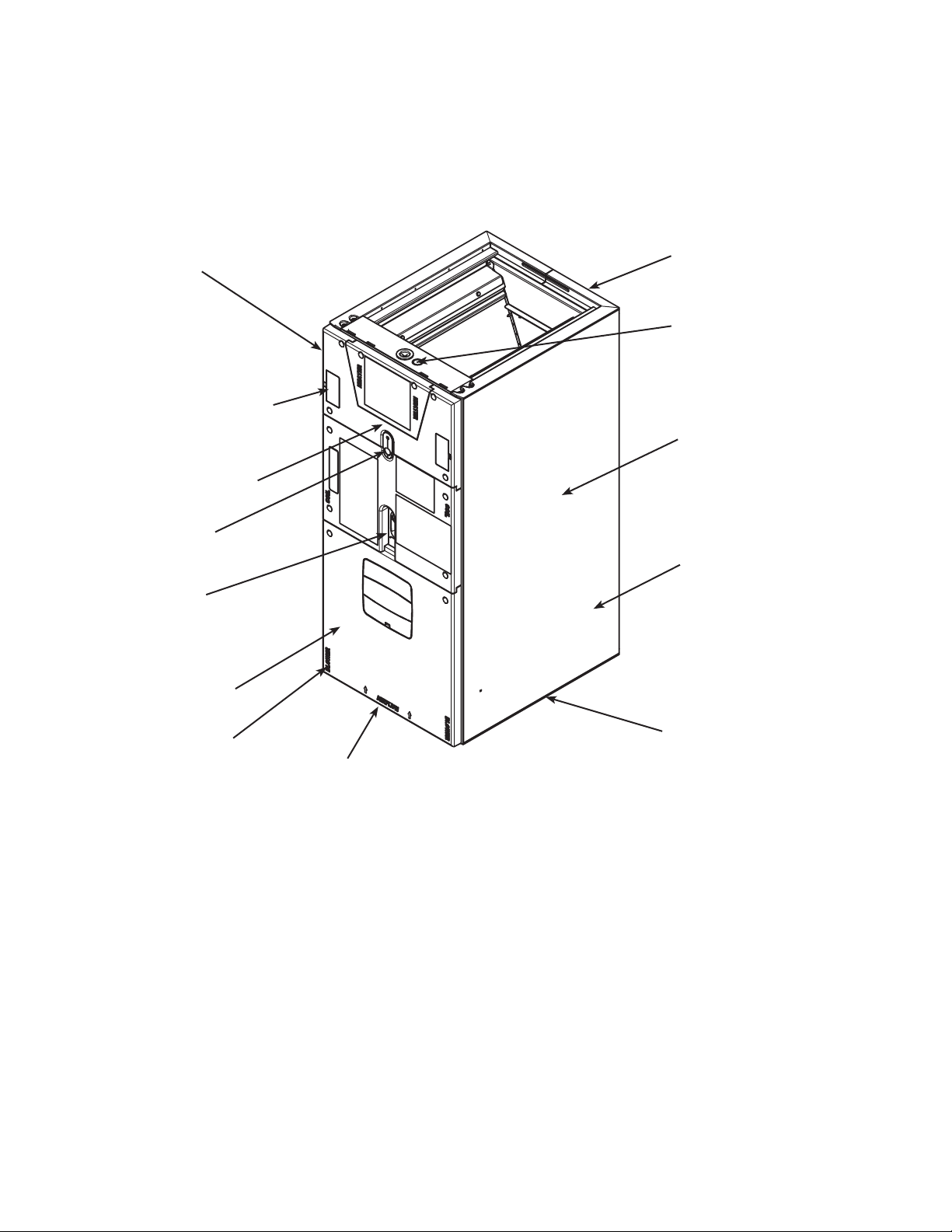
Unique Cabinet Design
Features and Benefits
2 Precision Durable
Door Seals
r Integrated Horizontal
Drain Pans
q Thermal Expansion
Valve (TXV)
3 Refrigeration
Connections
4 Condensate
Connections
8 VorticaTM Blower
and Deck
1 Unique Cabinet
Design
5 Conduit
Connection
Location
9 All Aluminum Coil
7 PSC 3 Speed
Motor
0 Labeled Panels
and Connections
1 Unique Cabinet Design
- Double wall foamed cabinet system
- Waterproof Cabinet Design
- R-4.2 Insulating Value (Avg. Insulating Value R-8)
- Composite Foamed Cabinet Doors
- Sweat Eliminating Cabinet Design
- Loose Fiber Eliminating Design
- Smooth Cleanable Cabinet Design
- 2% or Less air leakage
2 Precision Durable Door Seals
3 Brazed Refrigeration Connections
4 Primary/Secondary Condensate Connections
5 Conduit Connection - Conduit Connection on Top
7 PSC 3 Speed Motor
8 VorticaTM Blower and Deck - Polarized Plug on Blower
w Maximum width
is 17.5”
e Compact 20.8” Depth
with Doors Removed
9 All Aluminum Coil
- Integrated Slide Deck for Easy Removal
- Polarized Plug connections on Coil TXV
- Patented Enhanced Coil Fin
0 Labeled Panels and Connections
q R-410A Thermal Expansion Valve (TXV)
w Maximum width is 17.5”
e Compact 20.8” Depth with Doors Removed
r Integrated Horizontal Drain Pans
Pub. No. 22-1858-02 5
Page 6
General
Data
MODEL
RATED VOLTS/PH/HZ.
RATINGS 1
INDOOR COIL — Type
Rows — F.P.I.
Face Area (sq. ft.)
Tube Size (in.)
Refrigerant Control
Drain Conn. Size (in.) 2
DUCT CONNECTIONS
INDOOR FAN — Type
Diameter-Width (In.)
No. Used
Drive - No. Speeds
CFM vs. in. w.g.
No. Motors — H.P.
Motor Speed RPM
Volts/Ph/Hz
F.L. Amps - L.R. Amps
FILTER
Filter Furnished?
Type Recommended
No.-Size-Thickness
REFRIGERANT
Ref. Line Connections
Coupling or Conn. Size — in. Gas
Coupling or Conn. Size — in. Liq.
DIMENSIONS
Crated (In.)
Uncrated
WEIGHT
Shipping (Lbs.) / Net (Lbs.)
See Fan Performance Table
GAF2A0A18S11SA
208-230/1/60
See O.D. Specifications
Plate Fin
3 - 14
3.21
3/8
TXV
3/4 NPT
See Outline Drawing
Centrifugal
11 X 8
1
Direct - 3
1 - 1/3
825
208-230/1/60
2.0 - 4.1
No
Throwaway
1 - 16 X 20 - 1 in.
R-410A
Brazed
3/4
3/8
H x W x D
40.5 x 20 x 24.5
39.5 x 17.5 x 21.8
117/107
PRODUCT SPECIFICATIONS
GAF2A0A24S21SA
208-230/1/60
See O.D. Specifications
Plate Fin
3 - 14
3.21
3/8
TXV
3/4 NPT
See Outline Drawing
Centrifugal
10 X 8
1
Direct - 3
See Fan Performance Table
1 - 1/4
1075
208-230/1/60
1.3 - 2.6
No
Throwaway
1 - 16 X 20 - 1 in.
R-410A
Brazed
3/4
3/8
H x W x D
40.5 x 20 x 24.5
39.5 x 17.5 x 21.8
120/110
GAF2A0A30S21SA
208-230/1/60
See O.D. Specifications
Plate Fin
3 - 14
3.21
3/8
TXV
3/4 NPT
See Outline Drawing
Centrifugal
10 X 8
1
Direct - 3
See Fan Performance Table
1 - 1/3
1075
208-230/1/60
1.7 - 3.5
No
Throwaway
1 - 16 X 20 - 1 in.
R-410A
Brazed
3/4
3/8
H x W x D
40.5 x 20 x 24.5
39.5 x 17.5 x 21.8
121/111
GAF2A0A36S31SA
208-230/1/60
See O.D. Specifications
Plate Fin
3 - 14
3.21
3/8
TXV
3/4 NPT
See Outline Drawing
Centrifugal
11 X 8
1
Direct - 3
See Fan Performance Table
1 - 1/2
1075
208-230/1/60
2.4 - 3.8
No
Throwaway
1 - 16 X 20 - 1 in.
R-410A
Brazed
3/4
3/8
H x W x D
40.5 x 20 x 24.5
39.5 x 17.5 x 21.8
122/112
1 These Air Handlers are AHRI certified with various Split System Air Conditioners
and Heat Pumps (AHRI STANDARD 210/240). Refer to the Split System Outdoor
Unit Product Data Guides for performance data.
2 3/4" Male Plastic Pipe (Ref.: ASTM 1785-76)
6 Pub. No. 22-1858-02
Page 7

General
Data
GAF2A0A18 AIRFLOW PERFORMANCE TABLE
AIRFLOW PERFORMANCE
GAF2A0A18S11SA
EXTERNAL STATIC
(in w.g)
Speed Taps - 230 VOLTS Speed Taps - 208 VOLTS
3 2 † 1 3 2 † 1
0 952 768 710 940 654 598
0.1 894 741 687 885 636 581
0.2 845 704 658 831 610 558
0.3 785 662 620 775 577 526
0.4 724 607 568 714 529 477
0.5 652 531 494 640 460 415
0.6 557 441 404 543 378 347
0.7 428 346 N/A 418 244 N/A
0.8 284 N/A N/A 225 N/A N/A
0.9 N/A N/A N/A N/A N/A N/A
1.0 N/A N/A N/A N/A N/A N/A
NOTES:
1. Values are with wet coil and without filters.
2. Contact your particular filter manufacturer for pressure drop data.
3. Electric heater pressure drop is negligible and is included within the airflow data.
4. † Factory Setting
AIRFLOW (CFM)
GAF2A0A18S11SA MINIMUM HEATER AIRFLOW CFM
Heater Minimum Air Speed Tap
Without Heat Pump With Heat Pump
BAYECAA05LG1AA Tap 1 Tap 3
BAYECAA08LG1AA Available soon Available soon
BAYECAA10LG1AA Available soon Available soon
SEE AIR HANDLER NAMEPLATE OR PRODUCT DATA FOR EXCEPTIONS
Note: Heating and cooling speeds are the same, factory
set at Speed Tap #2.
Pub. No. 22-1858-02 7
Page 8

Performance
Data
GAF2A0A24 AIRFLOW PERFORMANCE TABLE
AIRFLOW PERFORMANCE
GAF2A0A24S21SA
EXTERNAL STATIC
(in w.g)
Speed Taps - 230 VOLTS Speed Taps - 208 VOLTS
3 2 † 1 3 2 † 1
0 998 848 771 899 737 658
0.1 949 816 745 868 710 630
0.2 911 784 711 834 683 602
0.3 869 750 679 794 650 567
0.4 825 708 638 756 611 524
0.5 772 659 586 704 547 476
0.6 707 591 518 641 499 415
0.7 614 513 444 555 420 346
0.8 533 416 356 465 339 268
0.9 413 309 218 351 203 138
1.0 241 130 N/A 167 N/A N/A
NOTES:
1. Values are with wet coil and without filters.
2. Contact your particular filter manufacturer for pressure drop data.
3. Electric heater pressure drop is negligible and is included within the airflow data.
4. † Factory Setting
AIRFLOW (CFM)
GAF2A0A24S21SA MINIMUM HEATER AIRFLOW CFM
Heater Minimum Air Speed Tap
Without Heat Pump With Heat Pump
BAYECAA05LG1AA Tap 1 Tap 2
BAYECAA08LG1AA Available soon Available soon
BAYECAA10LG1AA Available soon Available soon
SEE AIR HANDLER NAMEPLATE OR PRODUCT DATA FOR EXCEPTIONS
Note: Heating and cooling speeds are the same, factory
set at Speed Tap #2.
8 Pub. No. 22-1858-02
Page 9

Performance
Data
GAF2A0A30 AIRFLOW PERFORMANCE TABLE
AIRFLOW PERFORMANCE
GAF2A0A30S21SA
EXTERNAL STATIC
(in w.g)
Speed Taps - 230 VOLTS Speed Taps - 208 VOLTS
3 2 † 1 3 2 1
0 1052 967 932 1024 877 826
0.1 1012 929 898 980 846 800
0.2 963 888 861 934 814 771
0.3 914 849 823 885 777 738
0.4 865 805 784 837 739 703
0.5 816 759 741 788 697 663
0.6 759 698 681 739 640 602
0.7 690 622 592 668 559 515
0.8 589 503 463 559 423 395
0.9 389 336 318 375 285 259
1.0 179 149 119 175 NA NA
NOTES:
1. Values are with wet coil and without filters.
2. Contact your particular filter manufacturer for pressure drop data.
3. Electric heater pressure drop is negligible and is included within the airflow data.
4. † Factory Setting
GAF2A0A30S21SA MINIMUM HEATER AIRFLOW CFM
Heater Minimum Air Speed Tap
Without Heat Pump With Heat Pump
BAYECAA05LG1AA Tap 1 Tap 1
BAYECAA08LG1AA Available soon Available soon
BAYECAA10LG1AA Available soon Available soon
SEE AIR HANDLER NAMEPLATE OR PRODUCT DATA FOR EXCEPTIONS
Note: Heating and cooling speeds are the same, factory
set at Speed Tap #2.
Pub. No. 22-1858-02 9
Page 10

Performance
Data
GAF2A0A36 AIRFLOW PERFORMANCE TABLE
AIRFLOW PERFORMANCE
GAF2A0A36S31SA
EXTERNAL STATIC
(in w.g)
Speed Taps - 230 VOLTS Speed Taps - 208 VOLTS
3 2 † 1 3 2 1
0 1191 1146 1094 1040 1015 964
0.1 1180 1132 1085 1033 1004 959
0.2 1158 1110 1065 1014 984 942
0.3 1119 1082 1035 979 958 916
0.4 1079 1045 1003 942 923 887
0.5 1040 1005 969 907 886 857
0.6 993 960 927 864 843 818
0.7 934 910 877 808 795 772
0.8 880 855 816 758 742 715
0.9 815 786 748 696 675 650
1.0 744 715 677 629 607 583
NOTES:
1. Values are with wet coil and without filters.
2. Contact your particular filter manufacturer for pressure drop data.
3. Electric heater pressure drop is negligible and is included within the airflow data.
4. † Factory Setting
GAF2A0A36S31SA MINIMUM HEATER AIRFLOW CFM
Heater Minimum Air Speed Tap
Without Heat Pump With Heat Pump
BAYECAA05LG1AA Tap 1 Tap 1
BAYECAA08LG1AA Available soon Available soon
BAYECAA10LG1AA Available soon Available soon
SEE AIR HANDLER NAMEPLATE OR PRODUCT DATA FOR EXCEPTIONS
Note: Heating and cooling speeds are the same, factory
set at Speed Tap #2.
10 Pub. No. 22-1858-02
Page 11

Electrical
Data
WIRING DATA
GAF2A0A18S11SA
240 VOLT 208 VOLT
Heater
Model
No.
No Heater - - - 2.0** 3 15 - - 2.0** 3 15
BAYECAA05++ 1 4.80 16400 20 28 30 3.60 12300 17.3 24 25
BAYECAA08++ 1 7.68 26200 32 43 45 5.76 19700 27.7 37 40
BAYECAA10++ 1 9.60 32800 40 53 60 7.20 24600 34.6 46 50
Note: ** Motor Amps
No.
of
Circuits
Capacity
kW BTUH kW BTUH
Heater
Amps
per
Circuit
Minimum
Circuit
Ampacity
GAF2A0A24S21SA
Maximum
Protection
WIRING DATA
Overload
Capacity
Heater
Amps
per
Circuit
Minimum
Circuit
Ampacity
Maximum
Overload
Protection
240 VOLT 208 VOLT
Heater
Model
No.
No Heater - - - 1.3** 2 15 - - 1.3** 2 15
BAYECAA05++ 1 4.80 16400 20 27 30 3.60 12300 17.3 23 25
BAYECAA08++ 1 7.68 26200 32 42 45 5.76 19700 27.7 38 40
BAYECAA10++ 1 9.60 32800 40 52 60 7.20 24600 34.6 45 45
Note: ** Motor Amps
Heater
Model
No.
No Heater - - - 1.7** 2 15 - - 1.7** 2 15
BAYECAA05++ 1 4.80 16400 20 27 30 3.60 12300 17.3 24 25
BAYECAA08++ 1 7.68 26200 32 42 45 5.76 19700 27.7 38 40
BAYECAA10++ 1 9.60 32800 40 52 60 7.20 24600 34.6 45 45
Note: ** Motor Amps
No.
of
Circuits
No.
of
Circuits
Capacity
kW BTUH kW BTUH
Capacity
kW BTUH kW BTUH
Heater
Amps
per
Circuit
Heater
Amps
per
Circuit
Minimum
Circuit
Ampacity
GAF2A0A30S21SA
240 VOLT 208 VOLT
Minimum
Circuit
Ampacity
Maximum
Overload
Protection
WIRING DATA
Maximum
Overload
Protection
Capacity
Capacity
Heater
Amps
per
Circuit
Heater
Amps
per
Circuit
Minimum
Circuit
Ampacity
Minimum
Circuit
Ampacity
Maximum
Overload
Protection
Maximum
Overload
Protection
Pub. No. 22-1858-02 11
Page 12

Electrical
WHEEL
BLOWER HOUSING
BELLY BAND
MOTOR
A
A is determined per chart
Wheel is centered in
Blower Housing
Data
WIRING DATA
GAF2A0A36S31SA
240 VOLT 208 VOLT
Heater
Model
No.
No Heater - - - 2.4** 3 15 - - 2.4** 3 15
BAYECAA05++ 1 4.80 16400 20 28 30 3.60 12300 17.3 25 25
BAYECAA08++ 1 7.68 26200 32 43 45 5.76 19700 27.7 38 40
BAYECAA10++ 1 9.60 32800 40 53 60 7.20 24600 34.6 46 50
Note: ** Motor Amps
No.
of
Circuits
Capacity
kW BTUH kW BTUH
Heater
Amps
per
Circuit
Minimum
Circuit
Ampacity
Maximum
Overload
Protection
Capacity
Heater
Amps
per
Circuit
Minimum
Circuit
Ampacity
Maximum
Overload
Protection
DISTANCE FROM BELLY BAND TO SHAFT FACE OF MOTOR FOR MINIMUM VIBRATION
MODEL DIM "A"
GAF2A0A18S11SA 1-1/8
GAF2A0A24S21SA 2-11/16
GAF2A0A30S21SA 1-9/16
GAF2A0A36S31SA 1-11/16
12 Pub. No. 22-1858-02
Page 13

WIRING DIAGRAM FOR GAF2A0A18S, GAF2A0A24S, GAF2A0A30S, AND GAF2A0A36S AIR HANDLERS
Pub. No. 22-1858-02 13
Page 14

Air Handler Hook-up Diagram
Cooling
Field
Wiring
GAF2 AIR HANDLERS WITH SINGLE SPEED COOLING
W1 White
Comfort Control
White
Green
Yellow
Orange
Red
Blue
W
G
Y
O
R
B
Field wiring
Green
White
Green
Yellow
Red
Blue
Red
Blue
Air Handler
B - Blue
Y - Yellow
Air Conditioner
Blue
Yellow
14 Pub. No. 22-1858-02
Page 15

Field
Air Handler Hook-up Diagram
Wiring
GAF2 AIR HANDLERS WITH SINGLE SPEED HEAT PUMP
HP
Comfort Control
White
Green
Yellow
Orange
Red
Blue
W
G
Y
O
R
B
W1 White
Green
White
Green
Yellow
Orange
Red
Blue
Red
Blue
Air Handler
R - Red
B - Blue
Y - Yellow
Heat Pump
Black
(X2)
Orange
Red
Yellow
Blue
Field wiring
Pub. No. 22-1858-02 15
Page 16

GAF2
Convertibility
* Note: No internal modifications required for any position.
1 Badge rotation will keep brand in correct position
Multi-position Air Handler
Refrigerant
Connections
Low Voltage
Connections
inside unit
Upflow Configuration
1
Upflow
Condensate
Drains
Refrigerant
Connections
Horizontal Left
Condensate
Drains
Horizontal Left*
1
Low Voltage
Connections
inside unit
Airflow
Airflow
Airflow
Low Voltage
Connections
inside unit
1
Horizontal Right
Condensate
Drains
Refrigerant
Connections
Horizontal Right*
16 Pub. No. 22-1858-02
Page 17

Dimensions
GAF2 AIR HANDLER DIMENSIONAL DATA
W
H
Model
Number
GAF2A0A18S11SA 39 x 22 x 17.5 107
GAF2A0A24S21SA 39 x 22 x 17.5 110
GAF2A0A30S21SA 39 x 22 x 17.5 111
GAF2A0A36S31SA 39 x 22 x 17.5 112
H x D x W
in.
Unit
Net Weight
lbs.
GAF2 AIR HANDLERS ARE ALL ONE
PIECE CABINETS.
Pub. No. 22-1858-02 17
D
Page 18

GAF2 OUTLINE DRAWING
18 Pub. No. 22-1858-02
Page 19

Pub. No. 22-1858-02 19
Page 20

Trane
6200 Troup Highway
Tyler, TX 75707
www.trane.com
11/11
The manufacturer has a policy of continuous product and product data improvement and it reserves the right
to change design and specifications without notice.
 Loading...