

Page 1
Electric Wall Fin
Model EWFB — Electric Wall Fin
FIN-PRC003-ENOctober 2001
Page 2
Features
Trane electric natural convection heavy
duty wall fin has been designed to be
securely attached to the wall or as an
option floor mounted on pedestals.
Trane wall fin is ideally suited as a
primary heating source, a supplement in
high heat loss areas or as a draft barrier
to help minimize cold wall and window
conditions. Because of its rugged
construction, wall fin is especially
recommended for public areas in
commercial and institutional
applications such as offices, schools,
hospitals, transportation terminals,
churches, dormitories and nursing
homes.
The range of sizes and heat outputs can
be individually combined to form a truly
custom comfort system. The wide
variety of colors, materials and
accessories become architecturally
compatible with any interior concept and
design.
and
Benefits
Enclosure Options
Enclosures ranging from 2 5/8" (67 mm),
•
1
/2" (89 mm), 5" (127 mm) and
3
5 1/2" (140 mm) depths and 4" (102
mm), 4
7" (178 mm) heights. Model ASHDB is
available in 8" (203 mm) through
20" (508 mm) heights.
Front intake models may be installed
•
directly on finished floors.
2’ (.61 M) to 15’ (4.57 M) lengths.
•
1
•
extruded aluminum grilles and
extruded aluminum back.
One-piece front and top panel snap fits
•
to back cover for two-piece
construction.
Totally-enclosed junction boxes.
•
Full length thermal overload
•
protection.
Bonded aluminum fins for cool surface
•
temperatures.
Standard 1/2" (13 mm) EMT raceway
•
between junction boxes.
1
/2" (114 mm), 6" (152 mm),
/4" (6.4 mm) pencil-proof top discharge
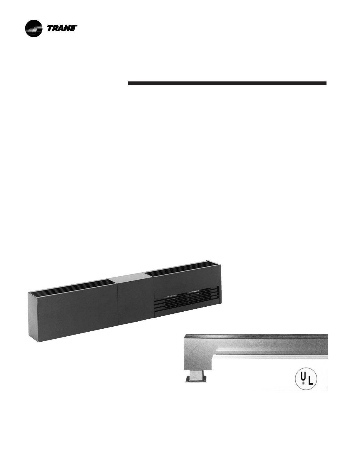
Model EWFB
Electric Wall Fin
Thermostats single or double-pole.
•
Disconnect switch, double-pole.
•
Transformer relay single-pole and
•
power relays.
Custom lengths to 1' (4.57 M).
•
6" (152 mm) and 12" (305 mm) control
•
sections for factory mounting of one to
two controls.
Extended enclosures extend heater’s
•
length in 6" (152 mm) increments to a
maximum length of 60" (1524 mm).
Blank enclosure sections for all models
•
to allow branch circuit wiring. Can be
modified for use with hydronic heating
elements.
Full line of field adjustable accessories
•
for virtually perfect wall-to-wall or
mullion-to-mullion fit without field
cutting. Approved as 40 ampere
wireways.
UL Listed.
•
1
/4" (6.4 mm) wire mesh, factory
•
installed on enclosure.
No visible mounting screws.
•
Pedestal brackets available for floor
•
mounting in lobbies or in front of
windows.
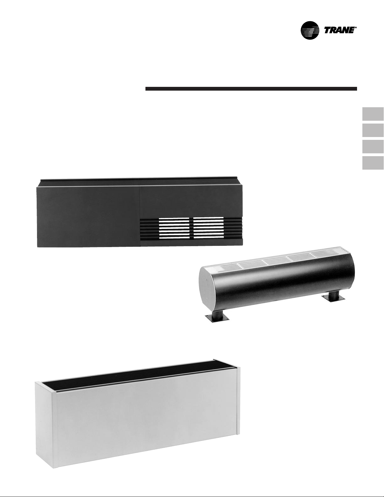
DBT — Wall Mount (Bottom Inlet)
1
/2" Deep x 6" High — 12-Gauge
3
Extruded Aluminum Front and Grille
DBF — Floor Mount (Front Inlet) for zero
clearance mounting
CB — Wall Mount (Bottom Inlet)
5
/8" Deep x 4 1/2" High —
2
14-Gauge Extruded Aluminum Front
and Grille
FIN-PRC003-EN© 2001 American Standard Inc. All rights reserved.
Page 3
Contents
DBCT — Bottom Inlet (Top Discharge)
DBCF — Front Inlet (Top Discharge)
5" Deep x 7" High — 10-Gauge Extruded
Aluminum Front and Grille
Features and Benefits
Dimensional Data
Wiring Diagrams
Mechanical Specifications
2
4
9
14
FIN-PRC003-EN
RDBT-PD Architectural Draft Barrier
6" Deep x 5" High — 12-Gauge Extruded
Pedestal Mount
ASHDB — 8 through 20
1
/2" Deep x 8" thru 20" High
5
Front Cover 16-Gauge Steel with
12-Gauge Extruded Aluminum Grille
3
Page 4
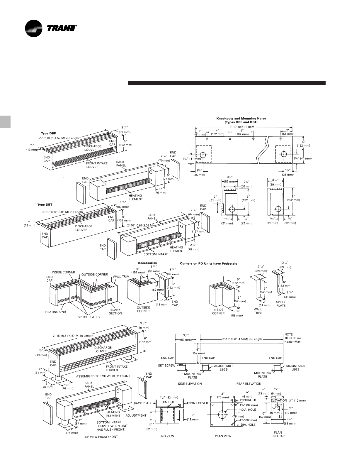
Dimensional Data Model EWFB
Type DBF Wall Mounted (Bottom Louver)
15' (4.57 M) Length DBF and DBT Only Wall Mounted
Architectural Pedestal Heaters
Series DBT and DBF
100-250 Watt Per Foot
FIN-PRC003-EN4
Page 5
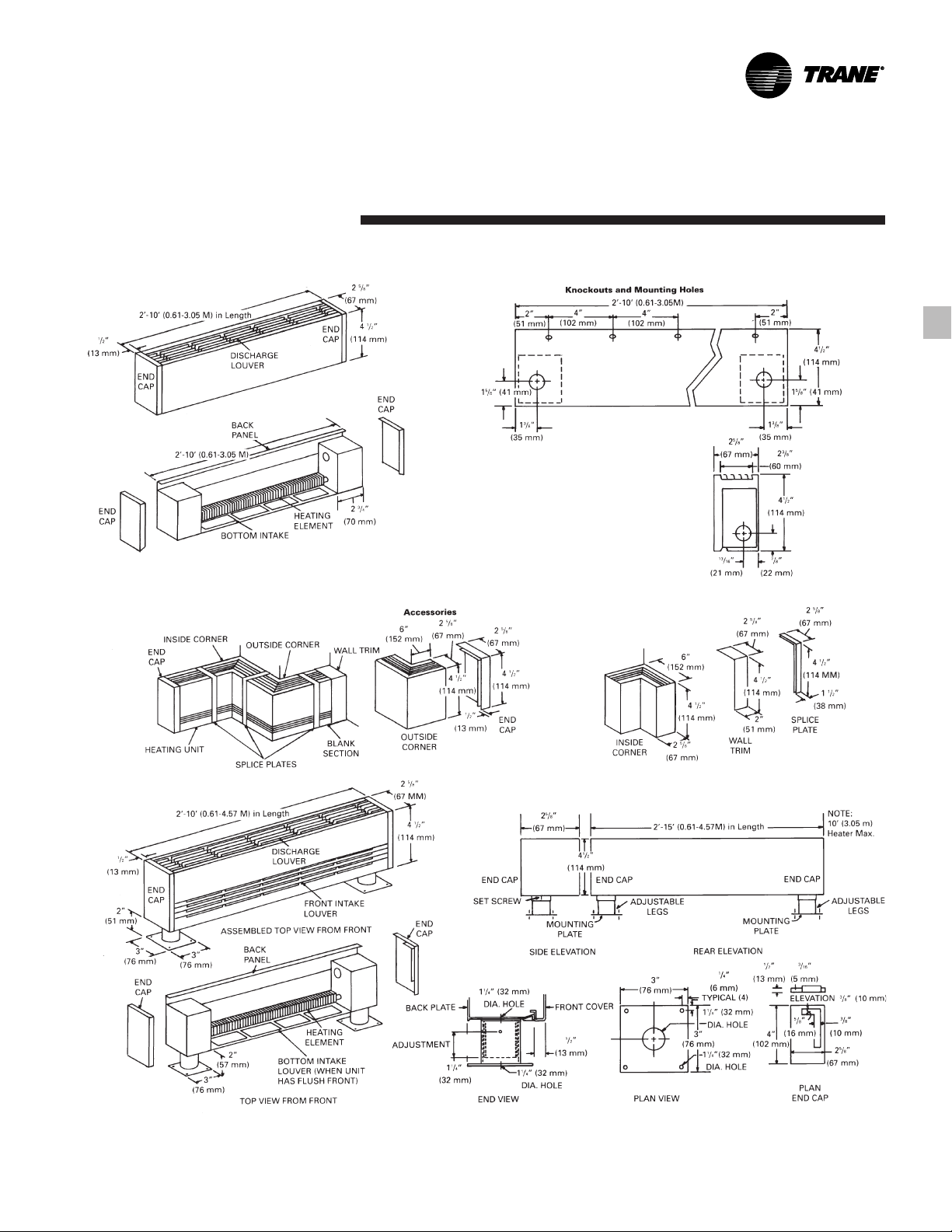
Dimensional
Type CB Wall Mounted
Typical Installation
Data
Model EWFB
FIN-PRC003-EN
Pedestal Heaters – Series CB
250 Watts Per Foot – Element Pedestals
5
Page 6
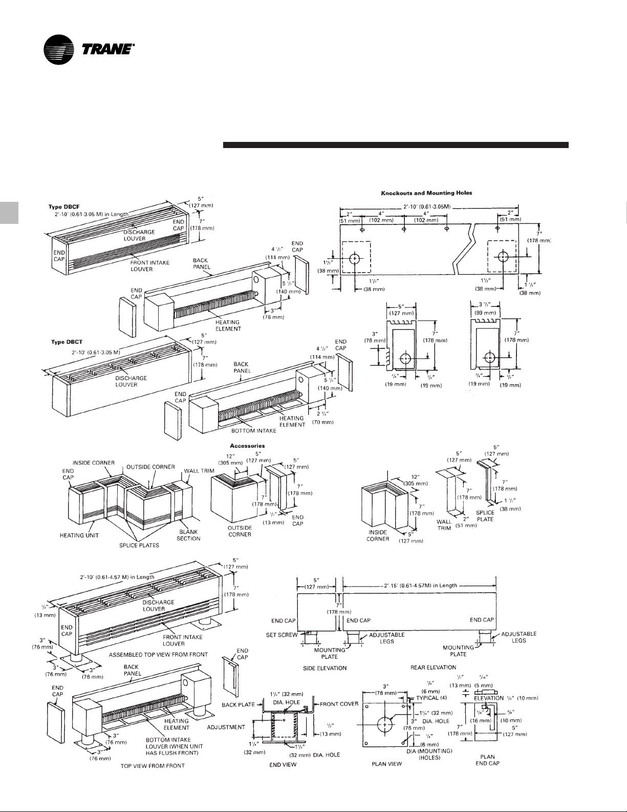
Dimensional
Data Model EWFB
Type DBCT and DBCF (Bottom Louver) Wall Mounted
Typical Installation
Architectural Pedestal Heaters
Series DBCF, DBCT
NOTE:
Front covers available as standard through 15’.
Backplate available as option through 15’.
FIN-PRC003-EN6
Page 7

Dimensional
Data
Model RDBT-PD Pedestal Floor Mounted
Unit Length
Dimension “A” Dimension “A”
2 Ft. 0.61
3 Ft. 0.91
4 Ft. 1.22
5 Ft. 1.52
6 Ft. 1.83
7 Ft. 2.13
8 Ft. 2.44
9 Ft. 2.74
Feet Meters
10 Ft. 3.05
Model EWFB
FIN-PRC003-EN
7
Page 8

Dimensional
Type ASHDB-8 thru 20 Wall Mounted
Knockouts and Mounting Holes
Data
Model EWFB
Typical Installation
*Architectural Pedestal Heaters –
Series ASHDB-8 8” High
100-500 Watts Per Foot
*8" high ASHDB unit is the only size that can be mounted on pedestals.
FIN-PRC003-EN8
Page 9

Wiring
Diagrams Model EWFB
Controls
Description — Single Pole
Catalog Number – DBF-ITS, DBT-ITS,
CDF-ITS, CDT-ITS
Rated 25 amps at 120-277 VAC. 50-110°F
temperature range. Tamperproof and
adjustable through discharge louver.
Description – Double Pole Thermostat
Catalog Number – DBF-ITD, DBT-ITD,
CDF-ITD, CDT-ITD
Rated 25 amps at 120-277 VAC. 50-110°F
temperature range. Tamperproof and
adjustable through discharge louver.
Description – Disconnect Switch
Catalog Number – DBF-IDS, DBT-IDS,
CDF-IDS, CDT-IDS
Double pole rated 20 amps at 120-277
VAC.
Wiring Diagrams
Field Wiring With Integral Controls
Integral thermostats: wire entry from
•
either end.
Disconnect switch: right hand wire
•
entry.
Thermostat and disconnect: right hand
•
wire entry.
Relays: right hand wire entry – control
•
section.
Thermostat – disconnect and relay:
•
right hand wire entry – control section.
When heaters are furnished with
controls, make certain that the heater or
heaters do not exceed the lowest
amperage rating of the controls
furnished. For example, if a thermostat
and disconnect are furnished, the
thermostat is rated at 25 amps 240 and
277, the disconnect is rated 20 amps 240
and 277. Therefore, the combination of
heaters should not exceed 20 amps at
277 or 240.
Wiring Diagrams – Control Section
FIN-PRC003-EN
9
Page 10

Wiring
Controls
Description – Single Pole
Catalog Number – CB-ITS
Rated 25 amps at 120-277 VAC. 50-110°F
temperature range. Tamperproof and
adjustable through discharge louver.
Description – Double Pole Thermostat
Catalog Number – CB-ITD
Rated 25 amps at 120-277 VAC. 50-110°F
temperature range. Tamperproof and
adjustable through discharge louver.
Description – Disconnect Switch
Catalog Number – CB-IDS
Double pole rated 20 amps at 120-277
VAC.
Wiring Diagrams
Diagrams
Field Wiring With Integral Controls
Integral thermostats: wire entry from
•
either end.
Disconnect switch: mount either end.
•
Thermostat and disconnect: mount
•
either end.
Relays: control section.
•
Thermostat – disconnect and relay:
•
control section
Note: Control section is attached on
either side.
Model EWFB
When heaters are furnished with
controls, make certain that the heater or
heaters do not exceed the lowest
amperage rating of the controls
furnished. For example, if a thermostat
and disconnect are furnished, the
thermostat is rated at 25 amps 240 and
277, the disconnect is rated 20 amps 240
and 277 VAC. Therefore, the combination
of heaters should not exceed 20 amps at
277 or 240 VAC.
Wiring Diagrams – Control Section
FIN-PRC003-EN10
Page 11

Wiring
Controls
Description – Single Pole
Catalog Number – DBCF-ITS, DBCT-ITS
Rated 25 amps at 120-277 VAC. 50-110°F
temperature range. Tamperproof and
adjustable through discharge louver.
Description – Double Pole Thermostat
Catalog Number – DBCF-ITD, DBCT-ITD
Rated 25 amps at 120-277 VAC. 50-110°F
temperature range. Tamperproof and
adjustable through discharge louver.
Description – Disconnect Switch
Catalog Number – DBCF-IDS, DBCT-IDS
Double pole rated 20 amps at 120-277
VAC.
Wiring Diagrams
Diagrams
Field Wiring With Integral Controls
Integral thermostats: wire entry from
•
either end.
Disconnect switch: right hand wire
•
entry.
Thermostat and disconnect: right hand
•
wire entry.
Relays: right hand wire entry – control
•
section.
Thermostat – disconnect and relay:
•
right hand wire entry – control section.
Model EWFB
When heaters are furnished with
controls, make certain that the heater or
heaters do not exceed the lowest
amperage rating of the controls
furnished. For example, if a thermostat
and disconnect are furnished, the
thermostat is rated at 25 amps 240 and
277, the disconnect is rated 20 amps 240
and 277. Therefore, the combination of
heaters should not exceed 20 amps at
277 or 240.
Wiring Diagrams – Control Section
FIN-PRC003-EN
11
Page 12

Wiring
Controls
Description – Single Pole
Catalog Number – RDBT-ITS
Rated 25 amps at 120-277 VAC. 50-110°F
temperature range. Tamperproof and
adjustable through discharge louver.
Description – Double Pole Thermostat
Catalog Number – RDBT-ITD
Rated 25 amps at 120-277 VAC. 50-110°F
temperature range. Tamperproof and
adjustable through discharge louver.
Description – Disconnect Switch
Catalog Number – RDBT-IDS
Double pole rated 20 amps at 120-277
VAC.
Wiring Diagrams
Diagrams
Field Wiring With Integral Controls
Integral thermostats: wire entry from
•
either end.
Disconnect switch: right hand wire
•
entry.
Thermostat and disconnect: right hand
•
wire entry.
Relays: right hand wire entry – control
•
section.
Thermostat – disconnect and relay:
•
right hand wire entry – control section.
Model EWFB
When heaters are furnished with
controls, make certain that the heater or
heaters do not exceed the lowest
amperage rating of the controls
furnished. For example, if a thermostat
and disconnect are furnished, the
thermostat is rated at 25 amps 240 and
277 VAC, the disconnect is rated
20 amps 240 and 277 VAC. Therefore, the
combination of heaters should not
exceed 20 amps at 277 or 240 VAC.
Wiring Diagrams – Control Section
FIN-PRC003-EN12
Page 13

Wiring
Diagrams
Catalog Number ASHDB
Heaters Over 5' (1.52 M) Long May Have Two Heating Elements
Wiring Diagram – Heater Only
Wiring Diagrams
Model EWFB
Wiring Diagrams – Control Section
FIN-PRC003-EN
13
Page 14

Mechanical
Specifications
Natural convection heavy-duty electric
wall fin are furnished to meet the
specified wattage, voltage and size. Units
installed and wired in accordance with
the manufacturer’s recommendations
and applicable national and local codes.
Mounting: Electric wall fin heaters
designed to be securely attached to the
wall (or optional floor mounted on
pedestals) per manufacturer’s
instructions. Heaters are wired for either
right or left hand entry where there are
no controls, otherwise entry will be in
the junction box containing controls.
Heaters with bottom air intake and top
air exit and front air intake (inlet grille)
and top air exit (both wall and pedestal
styles) must be mounted a minimum of
3" (76 mm) off the finished floor.
Heaters with front air intake (inlet grille)
and top air exit can be wall mounted at
the finished floor level and are approved
for zero clearance at the bottom.
Specifications
Heater Design: Units are of modern
square design, constructed of specified
materials and contain totally enclosed
junction boxes at both ends, aluminum
fin tube element(s), thermal overload
1
/2" (13 mm) EMT prewired
and a
40 ampere wireway. Heater lengths
furnished in 2 foot (0.6 M) through
10 foot (3.0 M) in 1 foot (0.3 M)
increments.
(19 mm) knockouts are provided on the
side and rear of the heaters junction box
to allow end to end wiring for wall
mounted units and in the bottom of the
junction box only for floor mounted
heaters.
Enclosure front panel are of one piece
construction suitable for architectural,
commercial and industrial use, with
1
/4" (6.4 mm) pencil-proof top air
discharge and or front air intake louvers.
Louvers discharge heated air at a 15
degree angle for cleaner operation. The
one-piece front panel is extruded for
maximum strength and is available in
1
/2" (13 mm) and 3/4"
Model EWFB
lengths to 15 feet (4.6 M). Front panel
snap fit to the back panel with out
fasteners for two-piece construction.
Back panel is pre-punched for easy
installation and is suitable for mullion to
mullion installation for wall mounted
heaters only.
Extended Enclosures: Are manufactured
with solid metal grilles and extends the
enclosure length another 6" (152 mm),
12" (305 mm), 18" (457 mm), 24" (610
mm), 30" (762 mm), 36" (914 mm), 42"
(1067 mm), 48" (1219 mm), 54" (1372
mm) and 60" (1524 mm). Heater and
Extended Enclosure are furnished as a
one piece unit. Used to factory mount 6"
(152 mm) and 12" (305 mm) Control
Sections. Left or right hand mounting of
the Control Section must be specified.
Maximum Length with Extended
Enclosures are 15 feet (4.6 M) for heater
models DBT, DBF and CB, 12 feet (3.7 M)
for heater models DBCT, DBCF and
RDBT-PD and 10 feet (3.04 M) for heater
model ASHDB.
FIN-PRC003-EN14
Page 15

Mechanical
Enclosure Models and Type:
Model DBT – Wall mounted (bottom air
•
inlet and top air outlet) are snap fit twopiece construction, 6" (152 mm) high x
1
/2" (89 mm) deep manufactured from
3
12-gauge (2.7 mm thickness) extruded
aluminum. Extrusion are .100" (2.5
mm) thick 6063 aluminum heat treated
to T-5 hardness. Backplates are 12gauge (2.7 mm thickness) extruded
aluminum. Maximum wattage is 300
watts per foot (984 watts per meter).
Model DBF – Wall mounted (bottom
•
front air inlet grille and top air outlet) is
snap fit two-piece construction,
6" (152 mm) high x 3
manufactured from 12-gauge (2.7 mm
thickness) extruded aluminum.
Extrusion is .100" (2.5 mm) thick 6063
aluminum heat treated to T-5 hardness.
Backplates are 12-gauge (2.7 mm
thickness) extruded aluminum for zero
clearance mounting. Maximum
wattage is 250 watts per foot (820
watts per meter).
1
/2" (89 mm) deep
Specifications
Model CB – Wall mounted (bottom air
•
inlet and top air outlet) are snap fit
two-piece construction, 4
high x 2
manufactured from 14-gauge (1.9 mm
thickness) extruded aluminum.
Extrusion is .70" (1.8 mm) thick 6063
aluminum heat treated to T-5 hardness.
Backplates are 14-gauge (1.9 mm
thickness) extruded aluminum.
Maximum wattage is 250 watts per
foot (820 watts per meter).
Model DBCT – Wall mounted (bottom
•
air inlet and top air outlet) are snap fit
two-piece construction, 7" (178 mm)
high x 5" (127 mm) deep manufactured
from 10-gauge (3.4 mm thickness)
extruded aluminum. Extrusion is .100"
(2.5 mm) thick 6063 aluminum heat
treated to T-5 hardness. Backplates are
10-gauge (3.4 mm thickness) extruded
aluminum. Maximum wattage is 750
watts per foot (2460 watts per meter).
Model DBCF – Wall mounted (front air
•
inlet grille and top air outlet) are snap
fit two-piece construction, 7" (178 mm)
high x 5" (127 mm) deep manufactured
from 10-gauge (3.4 mm thickness)
extruded aluminum. Extrusion is .100"
(2.5 mm) thick 6063 aluminum heat
treated to T-5 hardness. Backplates are
10-gauge (3.4 mm thickness) extruded
aluminum. Maximum wattage is 650
watts per foot (2133 watts per meter).
5
/8" (67 mm) deep
1
/2" (114 mm)
Model EWFB
Model RDBT-PD – Pedestal mounted
•
(bottom air intake and top air outlet)
enclosure are rounded with a flat top
air discharge, 5" (127 mm) high x
6" (152 mm) deep manufactured from
12-gauge (2.7 mm) thick extruded
aluminum. Extrusion is .100" (2.5 mm)
thick heat treated to T-5 hardness.
Pedestals are 2" (51 mm) high for
overall height of 7" (178 mm) from the
floor to the top of the enclosure.
Maximum wattage is 300 watts per
foot (984 watts per meter).
Model ASHDB – Wall mounted
•
(bottom air inlet and top air outlet) are
available in 8" (203 mm), 10" (254 mm),
12" (305 mm), 14" (356 mm), 16" (406
mm) 18" (457 mm) and 20" (508 mm)
heights in a 5
Enclosure front and back panel are
manufactured from 16-gauge (1.5 mm
thickness) steel and is snap fit twopiece construction. Discharge grille is
12-gauge (2.7 mm thickness) one piece
continuous extruded aluminum,
.100" (2.5 mm) thick 6063 aluminum
heat treated to T-5 hardness.
Maximum wattage is 500 watts per
foot (1640 watts per meter).
1
/2" (140 mm) depth.
FIN-PRC003-EN
15
Page 16

Mechanical
Heating Elements: Element(s) consist of
high quality nickel chromium alloy
resistance wire embedded and
completely surrounded by magnesium
oxide, enclosed and swaged in an
aluminum sheath. Aluminum fins are
mechanically bonded to the sheath for
efficient heat transfer. The element
fin temperature will not exceed
330°F (166°C) to help assure long
element life. The heating element is
center anchored and free floating at each
end on nylon bushings for quiet
operation.
Thermal Overload: A full length tubular
automatic reset thermal overload
disconnects the heating element(s) in the
event normal operating temperatures
are exceeded.
Volts/Phase: All models available in the
following volts and phase 208/1, 240/1,
277/1 or 120/1.
Specifications
Control Options: Built-in thermostat and
disconnect are rated for 20 amps, 120277 VAC. Transformer relay are rated 25
amp, 120-277 VAC and power relays
rated for 18 amps. They are factory
installed with one device per junction
box or a 6" (152 mm) long or 12" (305
mm) long control section can be used
due to the heaters size or more than two
controls are required per heater.
ITS – Single pole thermostat, 20 amp,
•
is adjustable thru discharge grille
factory mounted and wired in left hand
junction box.
ITD – Double pole thermostat, 20 amp,
•
is adjustable thru discharge grille
factory mounted and wired in left hand
junction box.
IDS – Double pole disconnect switch,
•
20 amp, is adjustable thru discharge
grille factory mounted and wired in
right hand junction box.
Model EWFB
ATR – Transformer relay single pole,
•
rated 25 amp 120-277 VAC contacts
rated up thru 277 volt and must be
specified. Coils are 24 volt and 120 volt
and must be specified.
PR 208/24, 18 amp power relay
•
contactor.
PR 240/24, 18 amp power relay
•
contactor.
PR 277/24, 18 amp power relay
•
contactor.
ATR – Transformer relays and all
•
PR-power relays require a control
section and a 12" (305 mm) long
extended enclosure for installation.
Watts/Foot
Models (Single Element Heaters) (Double Element Heaters)
DBT & 93, 125, 141, 188, 250 & 282 282
RDBT
DBF & 93, 125, 141, 188 & 250 None
CB
DBCF & 93, 125, 141, 188, 250, 282, 282, 376, 438 & 500
ASHDB 333 & 375
DBCT 93, 125, 141, 188, 250, 282, 282, 376, 438, 500, 564, 625,
Watts Per Foot Watts Per Foot
333 & 375 666 & 750
FIN-PRC003-EN16
Page 17

Mechanical
Control Sections:
6" (152 mm) long control section for
•
factory mounting of 1 or 2 controls.
Right or left side mounting are
available with right side being
standard. Requires one foot (0.3048 M)
of extended enclosure for installation.
Control sections are field wired to the
heater.
12" (305 mm) long control section for
•
factory mounting of 1, 2 or 3 controls.
Right or left side mounting are
available with right side being
standard. Requires one foot (0.3048 M)
of extended enclosure for installation.
Control sections are field wired to the
heater.
Accessories: Accessories are approved
as 40 ampere wireways and are of the
same material and compatible design
as the heater section.
Inside corners 90 - 180 degrees.
•
Outside corners 180 - 270 degrees.
•
End caps left or right hand.
•
2" (51 mm) and 6" (152 mm) wall trims.
•
1 1/2" (38 mm) splice plates.
•
1/4" (6.4 mm) wire mesh factory
•
installed under outlet grille on
enclosure and blank enclosure sections
and extended enclosure sections.
Specifications
Pedestals – Pedestal brackets are
•
available for floor mounting in lobbies
and in front of windows for all models
except ASHDB 10" (254 mm), 12" (305
mm), 14" (356 mm), 18" (457 mm) and
20" (508 mm) high heaters. Factory
installed to the bottom of the unit for
field furnished power wiring to be run
through the center of the pedestal into
the bottom of the units junction box for
connection to the heater.
The knockouts that are provided in the
side and rear of each heaters junction
box and the back panel mounting
holes for wall mounting of units are
not furnished when pedestals are
ordered.
2' to 6' (0.6 to 1.83 M) heaters require
two pedestals, 6' to 8' (1.83 to 2.44 M)
heaters require three pedestals,
9' (2.74 M) and 10' (3.05 M) heaters
require four pedestals.
Finished Back Panels – Finished back
•
panels either painted or anodized in
the same color as the heater are
available for pedestal floor mounted
heaters to be installed in front of
windows and in lobbies.
Blank enclosure sections manufactured
•
of solid metal grilles and are
independent pieces of enclosure not
joined to the heater and are fully
enclosed to allow branch circuit wiring.
Available in 1 foot (0.3048 M) through
10 foot (3.048 M) lengths in 1 foot
(0.3048 M) increments. Can be
modified for use with hydronic heating
elements for models DBT, DBF, DBCT,
DBCF and ASHDB only.
Model EWFB
Color Finish Options
•
- Clear Anodized
- Bronze Anodized
- Black Anodized
- Beige Baked Enamel* 2-7-2894
- White Baked Enamel* 2-1-5098
- Brown Baked Enamel* 2-7-3894
- Black Baked Enamel* 2-6-5054
*Colors per Electric Wall Fin Color
Selection Chart FIN-S-3.
Anodized colors available for all
•
models except Model ASHDB.
Hydronic Heating Units
Blank enclosure sections for use with
hydronic heating elements are modified
to have the air outlet grille and bottom
air inlet or bottom front air inlet grille in
the same configuration as listed above
for each model electric heater.
Maximum Element Fin Size per Model
Model Maximum Fin Size
DBT & 23/4" x 4" and 31/4" x 31/4"
DBCT 70 mm x 102 mm and 83 mm x 83 mm
DBF & 23/4" x 4" and 23/4" x 3"
DBCF 70 mm x 102 mm and 70 mm x 76 mm
ASHDB 41/4" x 41/4"
Note:
31/4" (83 mm) x 51/4" (133 mm) fin size and
23/4" (70 mm) x 5" (127 mm) fin size cannot be used with
these size enclosures.
108 mm x 108 mm
FIN-PRC003-EN
17
Page 18

Page 19

Page 20

The Trane Company
An American Standard Company
www.trane.com
For more information contact
your local sales office or
e-mail us at comfort@trane.com
Literature Order Number
File Number
Supersedes
Stocking Location
FIN-PRC003-EN
PL-TD-FIN-000-PRC003-EN-1001
FIN-DS-5 0798
La Crosse
Since The Trane Company has a policy of continuous product and product data improvement, it reserves the
right to change design and specifications without notice.
 Loading...