

Page 1
Installation, Operation,
and Maintenance
UniTrane™ Fan Coil and Force-Flo™ Cabinet Heater
200-1200 CFM
Models FC and FF
Low Vertical Models FCKB and FCLB
SAFETY WARNING
Only qualified personnel should install and service the equipment. The installation, starting up, and servicing
of heating, ventilating, and air-conditioning equipment can be h azardous an d r equir es specific kno wledg e and
training. Impro perly installed, adjusted or altered equipment b y an unqualified person could r esult in death or
serious injury. When working on the equipment, observe all precautions in the literature and on the tags,
stickers, and labels that ar e attached to the equipment.
June 2018
UNT-SVX07J-EN
Page 2
Introduction
Read this manual thoroughly before operating or servicing
this unit.
Warnings, Cautions, and Notices
Safety advisories appear throughout this manual as
required. Y our personal safety and the proper operation of
this machine depend upon the strict observance of these
precautions.
The three types of advisories are defined as follows:
WARNING
Proper Field Wiring and Grounding
Required!
Failure to follow code could result in death or serious
injury. All field wiring MUST be performed by qualified
personnel. Improperly installed and grounded field
wiring poses FIRE and ELECTROCUTION hazards. To
avoid these hazards, y ou MUST f ollow r equir ements for
field wiring installation and grounding as described in
NEC and your local/state electrica l codes.
WARNING
CAUTIONs
NOTICE:
Indicates a potentially hazardous
situation which, if not avoided, could
result in death or serious injury.
Indicates a potentially hazardous
situation which, if not avoided, could
result in minor or moderate injury. It
could also be used to alert against
unsafe practices.
Indicates a situation that could result in
equipment or property-damage only
accidents.
Important Environmental Concerns
Scientific research has shown that certain man-made
chemicals can affect the earth’s naturally occurring
stratospheric ozone layer when released to the
atmosphere. In particular, several of the identified
chemicals that may af fect the ozone layer are refrigerants
that contain Chlorine, Fluorine and Carbon (CFCs) and
those containing Hydrogen, Chlorine, Fluorine and
Carbon (HCFCs). Not all refrigerants containing these
compounds have the same potential impact to the
environment. T rane advocates the responsible handling of
all refrigerants-including industry replacements for CFCs
and HCFCs such as saturated or unsaturated HFCs and
HCFCs.
Important Responsible Refr igerant
Practices
Trane believes that responsible refrigerant practices are
important to the environment, our customers, and the air
conditioning industry. All technicians who handle
refrigerants must be certified according to local rules. F or
the USA, the Federal Clean Air Act (Section 608) sets for th
the requirements for handling, reclaiming, recovering and
recycling of certain refrigerants and the equipment that is
used in these service procedures. In addition, some states
or municipalities may have additional requirements that
must also be adhered to for responsible management of
refrigerants. Know the applicable laws and follow them.
WARNING
Personal Protective Equipment (PPE)
Required!
Failur e t o w ear pro per PPE f or the job being under taken
could result in death or serious injury. Technicians, in
order to protect themselves from potential electrical,
mechanical, and chemical hazards, MUST follow
precautions in this manual and on the tags, stickers,
and labels, as well as the instructions below:
• Before installing/servi cin g th is un it, technicians
MUST put on all PPE required for the work being
undertaken (Examples; cut r esistant glo v es/sleeves,
butyl gloves, saf ety glasses, hard hat/bump cap, fall
protection, electrical PPE and arc flash clothing).
ALWAYS refer to appropriate Material Safety Data
Sheets (MSDS)/Safety Data Sheets (SDS) and OSHA
guidelines for proper PPE.
• When working with or ar ound hazar dous chemi cals,
ALWAYS refer to the appropriate MSDS/SDS and
OSHA/GHS (Global Harmonized System of
Classification and Labelling of Chemicals) guidelines
for information on allowable personal exposure
levels, proper respiratory protection and handling
instructions.
• If there is a risk of ener gized electr ical contac t, arc, or
flash, technicians MUS T put on all PPE in accor dance
with OSHA, NFPA 70E, or other country-specific
requirements for arc flash protection, PRIOR to
servicing the unit. NEVER PERFORM ANY
SWITCHING, DISCONNECTING, OR VOLTAGE
TESTING WITHOUT PROPER ELECTRICAL PPE AND
ARC FLASH CLOTHING. ENSURE ELECTRICAL
METERS AND EQUIPMENT ARE PROPERLY RATED
FOR INTENDED VOLTAGE.
© 2018 Ingersoll Rand UNT-SVX07J-EN
Page 3
WARNING
Follow EHS Policies!
Failure to follow instructions below could result in
death or serious injury.
• All Ingersoll Rand personnel must f ol low Ingersoll
Rand Environmental, Health and Safety (EHS)
policies when performing work such as hot work,
electrical, fall protection, lockout/tagout, refrigerant
handling, etc. All policies can be found on the BOS
site. Where local regulations ar e more str ingent than
these policies, those regulations supersede these
policies.
• Non-Ingersoll Rand personnel should always follow
local regulations.
Copyright
This document and the information in it are the property of
Trane, and may not be used or reproduced in whole or in
part without written permission. Trane reserves the right
to revise this publication at any time, and to make changes
to its content without obligation to notify any person of
such revision or change.
Introduction
Trademarks
All trademarks referenced in this document are the
trademarks of their respective owners.
Revision History
Updated for valve change.
UNT-SVX07J-EN 3
Page 4

Table of Contents
Model Number Descriptions . . . . . . . . . . . . . . 5
UniTrane™ Fan Coil/ Force Flo™ Cabinet
Heater
UniTrane™ Fan Coil Low Vertical Model . . 8
. . . . . . . . . . . . . . . . . . . . . . . . . . . . . . . . 5
General Information . . . . . . . . . . . . . . . . . . . . 10
Pre-Installation . . . . . . . . . . . . . . . . . . . . . . . . . 11
Receiving and Handling . . . . . . . . . . . . . . . 11
Jobsite Storage . . . . . . . . . . . . . . . . . . . . . . 11
Site Preparation . . . . . . . . . . . . . . . . . . . . . . 12
Dimensions and Weights . . . . . . . . . . . . . . . . 13
Service Clearances . . . . . . . . . . . . . . . . . . . . 13
Component Data . . . . . . . . . . . . . . . . . . . . . 14
Available Models . . . . . . . . . . . . . . . . . . . . . 15
Coil Connections . . . . . . . . . . . . . . . . . . . . . 41
Fresh Air Opening Locations . . . . . . . . . . . 45
Wall Box . . . . . . . . . . . . . . . . . . . . . . . . . . . . 47
Projection Panel . . . . . . . . . . . . . . . . . . . . . . 48
Installation—Mechanical . . . . . . . . . . . . . . . . 49
Installation Checklist . . . . . . . . . . . . . . . . . . 49
Installing the Unit . . . . . . . . . . . . . . . . . . . . . 50
Duct Connections . . . . . . . . . . . . . . . . . . . . . 52
Coil Piping and Connections . . . . . . . . . . . . . 53
Piping Package Components . . . . . . . . . . . 54
Hydronic Coil Piping . . . . . . . . . . . . . . . . . . 54
Water Piping Connections . . . . . . . . . . . . . 54
Condensate Drain Connections . . . . . . . . . 55
External Insulating Requirements . . . . . . . 56
Balancing Manual Circuit Setter Valve . . . 57
Installation - Electrical . . . . . . . . . . . . . . . . . . . 60
Unit Wiring Diagrams . . . . . . . . . . . . . . . . . 60
Supply Power Wiring . . . . . . . . . . . . . . . . . 60
Electrical Grounding Restrictions . . . . . . . 60
Interconnection Wiring . . . . . . . . . . . . . . . . 60
MCA and MOP Calculations . . . . . . . . . . . . 61
ECM Overview and Setup . . . . . . . . . . . . . . . 65
Overview . . . . . . . . . . . . . . . . . . . . . . . . . . . . 65
Electronically Commutated Motor (ECM) 65
VelociTach Motor Control Board . . . . . . . . 66
Installation and Initial Setup . . . . . . . . . . . .67
Adjustments . . . . . . . . . . . . . . . . . . . . . . . . . .72
Configurations . . . . . . . . . . . . . . . . . . . . . . . .75
Installation - Controls . . . . . . . . . . . . . . . . . . . .80
Control Options . . . . . . . . . . . . . . . . . . . . . . .80
Installation - Controllers . . . . . . . . . . . . . . . . . .84
Tracer® ZN010 and ZN510 Controllers . . .84
Tracer® ZN520 Controller . . . . . . . . . . . . . .84
Tracer® UC400-B Controller . . . . . . . . . . . .85
Air-Fi® Wireless Communications System 89
Zone Sensor Options . . . . . . . . . . . . . . . . . . . .91
Zone Sensor Installation . . . . . . . . . . . . . . . .92
Zone Sensor Settings . . . . . . . . . . . . . . . . . .95
Sensor Operations . . . . . . . . . . . . . . . . . . . . .97
Wireless Sensor Specifications . . . . . . . . . .98
Agency Compliance . . . . . . . . . . . . . . . . . . .99
Wireless Display Sensor (WDS) . . . . . . . . .99
Startup . . . . . . . . . . . . . . . . . . . . . . . . . . . . . . . .103
Pre-Startup Checklist . . . . . . . . . . . . . . . . . .103
Unit Startup . . . . . . . . . . . . . . . . . . . . . . . . .104
Tracer® ZN010/ZN510 Controllers . . . . . .104
Tracer® ZN520 Controllers . . . . . . . . . . . .106
Tracer® UC400-B Controller . . . . . . . . . . .114
Routine Maintenance . . . . . . . . . . . . . . . . . . .122
Maintenance Checklist . . . . . . . . . . . . . . . .122
Air Filters . . . . . . . . . . . . . . . . . . . . . . . . . . . .122
Coils . . . . . . . . . . . . . . . . . . . . . . . . . . . . . . . .123
Control Device Replacement . . . . . . . . . . .125
Drain Pans . . . . . . . . . . . . . . . . . . . . . . . . . . .125
Fans . . . . . . . . . . . . . . . . . . . . . . . . . . . . . . . .127
Diagnostics and Troubleshooting . . . . . . . .130
Fan Coil and Cabinet Heater . . . . . . . . . . .130
Wireless Zone Sensors (WZS) . . . . . . . . . .131
Servicing/Testing Wireless Zone Sensors 136
ZN010, ZN510, and ZN520 Controllers . . .137
Tracer® UC400-B Controller . . . . . . . . . . .143
ECM Motors . . . . . . . . . . . . . . . . . . . . . . . . .150
Wiring Diagrams . . . . . . . . . . . . . . . . . . . . . . .156
4 UNT-SVX07J-EN
Page 5

Model Number Descriptions
UniTrane™ Fan Coil/ Force Flo™ Cabinet Heater
Following is a complete description of
the UniTrane fan coil and Force Flo
cabinet heater model number. Each digit
in the model number has a
corresponding code that identifies
specific unit options.
Note: Not all options are available on all
cabinet styles. Contact your local
Trane sales representative for
more information.
Digits 1, 2 — Unit Type
FC = Fan Coil
FF = Force Flo
Digit 3 — Model
A = Vertical concealed
B = Vertical cabinet
C = Horizontal concealed
D = Horizontal cabinet
E = Horizontal recessed
F = Vertical Wall-hung
H = Vertical recessed
J = Vertical slope-top
M = Inverted vertical cabinet
N = Inverted vertical recessed
P = Compact concealed
Digit 4 — Development
Sequence
B = Development B
Digits 5, 6, 7 — Unit Cabinet
Size
020= 200 cfm
030= 300 cfm
040= 400 cfm
060= 600 cfm
080= 800 cfm
100 = 1000 cfm
120 = 1200 cfm
Digit 8 — Unit Voltage
1 = 115 V/60 Hz/1 PH
2 = 208 V/60 Hz/1 PH
3 = 277 V/60 Hz/1 PH
4 = 230 V/60 Hz/1 PH
5 = 208 V/60 Hz/3 PH
6 = 230 V/60 Hz/3 PH
7 = 480 V/60 Hz/3 PH
8 = 115 V/50 Hz/1 PH (SOS ONLY)
9 = 220-240 V/50 Hz/1 PH
A = 220-240 V/50 Hz/3 PH
B = 380-415 V/50 Hz/3 PH
Digit 9 — Piping System /
Placement
A = Without pipe, RH, Without
auxiliary
B = Without pipe, LH, Without
auxiliary
C = Without pipe, RH, With auxiliary
D = Without pipe, LH, With auxiliary
E = Without pipe, RH, Without
auxiliary, Extended end
F = Without pipe, LH, Without
auxiliary, Extended end
G = Without pipe, RH, With auxiliary,
Extended end
H = Without pipe, LH, With auxiliary,
Extended end
J = With pipe, RH
K = With pipe, LH
L = With pipe, RH, Extended end
M = With pipe, LH, Extended end
N = Without pipe, RH, With auxiliary,
Extended end pipe and control
side
P = Without pipe, LH, With auxiliary,
Extended end pipe and control
side
Q = With pipe, RH, With auxiliary,
Extended end pipe and control
side
R = With pipe, LH, With auxiliary,
Extended end pipe and control
side
Digits 10, 11 — Design
Sequence
***= Factory assigned
AW = AW design
Digit 12 — Inlet Style
A = Front toe space
B = Front bar grille
C = Front stamped louver
D = Bottom stamped louver
E = Bottom toe space
F = Back duct collar
G = Back exposed fan
H = Back stamped louver
J = Top duct collar
K = Exposed fan
L = Bottom filter
Digit 13 — Outside Air Damper
0=None
A = Manual, Bottom opening
B = Manual, Back opening
C = Manual, Top opening
D = Auto, 2-position, Bottom
opening
E = Auto, 2-position, Back opening
F = Auto, 2-position, Top opening
G = Economizer, Bottom
opening
H = Economizer, Back opening
J = Auto, Economizer, Top opening
K = No damp, Bottom opening
L = No damp, Back opening
M = No damp, Top opening
Digit 14 — Outlets Style
A = Front duct collar
B = Front bar grille
C = Front stamped louver
D = Front quad grille
E = Bottom duct collar
F = Bottom stamped louver
G = Top quad grille
H = Top bar grille
J = Top duct collar
K = Bottom bar grille
Digit 15 — Paint Cabinet Color
0 = None (Not painted unit)
1 = Deluxe beige
2=Soft dove
3=Cameo white
4 = Driftwood grey
5 = Stone grey
6=Rose mauve
Digit 16 — Tamperproof Locks /
Leveling Feet
0=None
A = Locking panel
B = Keylock access door
C = Locking panel, Keylock access
door, Secure grille
D = Leveling feet
E = Locking panel with
leveling feet
F = Keylock door with
level feet
G = Locking panel, Key access door,
Secure grille, Leveling feet
Digit 17 — Motor Types
A = Free discharge
B = High static
Digit 18 — Main Coil
A = 2-row cooling/heating
B = 3-row cooling/heating
C = 4-row cooling/heating
D = 2-row cooling, 1-row heating
E = 2-row cooling, 2-row heating
F = 3-row cooling, 1-row heating
G = 2-row cooling only or heating
only
H = 3-row cooling only or heating
only
J = 4-row cooling only or heating
only
K = 2-row cooling/heating, Electric
heat
L = 3-row cooling/heating, Electric
heat
M = 4-row cooling/heating, Electric
heat
N = Electric heat only, 1 stage
P = 2-row cooling/heating, 1-row
heating
Q = 2-row cooling/heating, 2-row
heating
R = 3-row cooling/heating, 1-row
heating
U = Electric heat only, 2 stage
V = Electric heat, Low kW, 1 stage
W = Steam coil
X = 2-row cooling only, Electric
heat
Y = 3-row cooling only, Electric
heat
Z = 4 -row cooling only, Electric
heat
1 = 3-row cooling, 1-row heating
with high capacity
2 = 3-row cooling/
heating, 1-row heating with high
capacity
3 = Heat pump
UNT-SVX07J-EN 5
Page 6

Model Number Descriptions
4 = Heat pump, Auxiliary electric
heat
5 = DX cooling
6 = DX cooling, Electric preheat
Digit 19 — Drain Pan
0 = None - Electric heat only
3 = Polymer drain pan
4 = Stainless steel drain pan
Digit 20 — Air Vent
0=None
A = Automatic
M= Manual
Digits 21, 22, 23 — Electric Heat
kW
000 = None
010 = 1.0 kW (0.75 kW 208 V)
015= 1.5 kW (1.1 kW 208 V)
020= 2.0 kW (1.5 kW 208 V)
025= 2.5 kW (1.9 kW 208 V)
030= 3.0 kW (2.2 kW 208 V)
040= 4.0 kW (3.0 kW 208 V)
045= 4.5 kW (3.3 kW 208 V)
050= 5.0 kW (3.7 kW 208 V)
060= 6.0 kW (4.4 kW 208 V)
070= 7.0 kW (5.3 kW 208 V)
075= 7.5 kW (5.7 kW 208 V)
080= 8.0 kW (6.0 kW 208 V)
090= 9.0 kW (6.6 kW 208 V)
100 = 10.0 kW (N/A 208 V)
105= 10.5 kW (7.9 kW 208 V)
110 = 11.0 kW (9.0 kW 208 V)
120= 12.0 kW (N/A 208 V)
135= 13.5 kW (10.2 kW 208 V)
150= 15.0 kW (N/A 208 V)
180= 18.0 kW (13.5 kW 208 V)
200= 20.0 kW (15.0 kW 208 V)
200= 21.0 kW (15.0 kW 208 V)
220= 22.0 kW (16.4 kW 208 V)
Digit 24 — Reheat Coil
0 = Without reheat
A = Steam reheat (4 FPI)
B = Hot water reheat (4 FPI)
D = High capacity hot water reheat
(12 FPI)
Digit 25 — Unit Mounted
Disconnect Switc h
0=None
D = With disconnect switch
Digit 26 — Filter Type
0=None
1 = 1-in. throwaway
2 = 1-in. throwaway MERV 8
3 = 1-in. throwaway, one extra
4 = 1-in. throwaway MERV 8,
one extra
5 = 1-in. throwaway, two extras
6 = 1-in. throwaway MERV 8,
two extras
7 = 1-in. throwaway, three extras
8 = 1-in. throwaway MERV 8,
three extras
A = 1-in. throwaway MERV 13
B = 1-in. throwaway MERV 13,
one extra
C = 1-in. throwaway MERV 13,
two extras
D = 1-in. throwaway MERV 13,
three extras
6 UNT-SVX07J-EN
Digit 27 — Future Option
0=None
Digit 28 — Future Option
0=None
Digit 29 — Piping Packages
0=None
A = Basic - Ball valve supply and
B = Basic - Ball valve supply and
E = Deluxe - Ball valve supply and
F = Deluxe - Ball valve supply and
return
manual circuit setter return
manual circuit setter return
return with auto flow
Digit 30 — Control Type
A = Fan speed control
E = Tracer® ZN010
F = Tracer® ZN510
G = Tracer® ZN520
H = Customer Supplied Terminal -
STAT Interface (CSTI)
L = Tracer® UC400-B
M = Tracer® UC400-B with
N = CSTI with fan status
Wireless Communications
Interface (WCI)
Digit 31 — Control Options
0=None
V = Unit-mounted zone sensor
module (OALMH and Setpoint
dial)
W = Wall-mounted zone sensor
X = Unit-mounted fan mode switch,
Y = Unit-mounted fan mode switch,
Z = Unit-mounted zone sensor
1 = Wall-mounted zone sensor
2 = Wall-mounted zone sensor
4 = Wall-mounted digital zone
6 = Wireless zone sensor (Setpoint
7 = Wireless display sensor, Unit8 = Unit-mounted variable speed
9 = Wall-mounted variable speed
module (OALMH and Setpoint
dial)
Wall-mounted zone sensor
(Setpoint dial)
Wall-mounted zone sensor
(Setpoint dial, On/CANCEL,
Comm. jack)
module (OALMH, Setpoint dial,
On/CANCEL buttons)
module (On/CANCEL buttons,
Comm. jack)
module (OALMH, Setpoint dial,
On/CANCEL, Comm. jack)
sensor (O/A/H/M/L, Setpoint dial,
On/CANCEL, Comm. jack)
dial, Occupied/Unoccupied
buttons)
receiver (OALMH)
control
control
Digit 32 — IAQ Options
0=None
1 = Dehumidification
2 = VOC/CO
3 = Dehumidification and VOC/CO
4 = Dehumidification with sensor
2
2
5 = Air-Fi® Dehumidification and
6 = Air-Fi® Dehumidification with
7=Air-Fi® CO
VOC/CO
sensor
2
2
Digit 33 — FLA Motor Options
0 = Standard ECM
A = Reduced FLA
Digit 34 - Control Options
0 = None
A = Low limit sensor
B = Condensate overflow
C = Low limit and condensate
overflow
Digit 35 — Main Valve Type
0=None
A = 2-way, 2-position N.C
B = 2-way, 2-position N.O
C = 3-way, 2-position N.C
D = 3-way, 2-position N.O
E = 2-way, Modulating
F = 3-way, Modulating
G = 2-way, Analog (2-10 VDC)
H = 3-way, Analog (2-10 VDC)
J = Field supplied, 2-position N.C
K = Field supplied, 2-position N.O
L = Field supplied, Modulating
M = Field supplied, Analog (2-10
VDC)
Digit 36 — Cv Main Valve
0=None
A = 2-way 1.4 Cv
B = 2-way 2.4 Cv
C = 2-way 3.4 Cv
D = 3-way 1.0 Cv
E = 3-way 2.7 Cv
F = 3-way 4.6 Cv
Digits 37 — Auxiliary Valve Type
0=None
A = 2-way, 2-position N.C.
B = 2-way, 2-position N.O.
C = 3-way, 2-position N.C.
D = 3-way, 2-position N.O.
E = 2-way, Modulating
F = 3-way, Modulating
G = 2-way, Analog (2-10 VDC)
H = 3-way, Analog (2-10 VDC)
J = Field supplied, 2-position N.C.
K = Field supplied, 2-position N.O.
L = Field supplied, Modulating
M = Field supplied, Analog (2-10
VDC)
Digits 38 — Cv Auxiliary Valve
0=None
A = 2-way 1.4 Cv
B = 2-way 2.4 Cv
C = 2-way 3.4 Cv
D = 3-way 1.0 Cv
E = 3-way 2.7 Cv
F = 3-way 4.6 Cv
Page 7

Model Number Descriptions
Digit 39 — Recessed Options
0=None
A = 5/8 in. standard recessed panel
B = 2 in. projection panel
C = 2.5 in. projection panel
D = 3 in. projection panel
E = 3.5 in. projection panel
F = 4 in. projection panel
G = 4.5 in. projection panel
H = 5 in. projection panel
J = 5.5 in. projection panel
K = 6 in. projection panel
L = 2 in. Falseback
M = 3 in. Falseback
N = 4 in. Falseback
P = 5 in. Falseback
Q = 6 in. Falseback
R = 7 in. Falseback
T = 8 in. Falseback
Digit 40 — Main Auto Flow GPM
0=None H=3.5
B = 0.75 J = 4.0
C=1.0 K=4.5
D=1.5 L=5.0
E=2.0 M=6.0
F=2.5 N=7.0
G=3.0 P= 8.0
Digit 41 — Auxiliary Auto Flow
GPM
0=None H=3.5
B = 0.75 J = 4.0
C=1.0 K=4.5
D=1.5 L=5.0
E=2.0 M=6.0
F=2.5 N=7.0
G=3.0 P=8.0
Digit 42 — Subbases
0=None
A = 2 in. height
B = 3 in. height
C = 4 in. height
D = 5 in. height
E = 6 in. height
F = 7 in. height
Digit 43 — Recessed Flange
0=None
A = With recessed flange
Digit 44 — Wall Box
0=None
A = Clear anodized
UNT-SVX07J-EN 7
Page 8

Model Number Descriptions
UniTrane™ Fan Coil Low Vertical Model
Following is a complete description
of the UniTrane fan coil low height
vertical model.
Digits 1, 2 — Unit Type
FC = Fan Coil
Digit 3 — Unit Model Type
K = Low vertical concealed
L = Low vertical cabinet
Digit 4 — Development
Sequence
B = Development B
Digit 5, 6, 7— Unit cfm
030= 300 cfm
040= 400 cfm
060= 600 cfm
Digit 8 — Unit Voltage
1 = 115 V/60 Hz/1 PH
2 = 208 V/60 Hz/1 PH
3 = 277 V/60 Hz/1 PH
4 = 230 V/60 Hz/1 PH
Digit 9 — Piping system
placement
C = Without piping, Right hand, With
aux drain pan
D = Without piping, Left hand, With
aux drain pan
J = With piping, Right hand, With
aux drain pan
K = With piping, Left hand, With
aux drain pan
Digit 10, 11— Design Sequence
** = Factory assigned
Digit 12 — Inlet
A = Front toe space
B = Front bar grille
Digit 13 — Outside Air Damper
0=None
B = Manual, Back opening
E = Auto, 2-position, Back
opening
Digit 14 — Outlet
G = Top quad grille
H = Top bar grille
J = Top duct collar
Digit 15 — Unit Color
0=None
1 = Deluxe beige
2=Soft dove
3=Cameo white
4 = Driftwood grey
5 = Stone grey
6=Rose mauve
7 = To be selected later
Digit 16 — Tamperproof Locks/
Leveling Feet
0=None
B = Keylock access door
D = Leveling feet
F = Keylock access door with
leveling feet
Digit 17 — Coil Type
A = 2-row cooling/heating
B = 3-row cooling/heating
C = 4-row cooling/heating
D = 2-row cooling, 1-row heating
E = 2-row cooling, 2-row heating
F = 3-row cooling, 1-row heating
K = 2-row cooling/heating, Electric
P = 2-row cooling/heating, 1-row
Q = 2-row cooling/heating
R = 3-row cooli ng/heating,1-row
X = 2-row cooling only, Electric heat
heat
heating
heating
heating
,
2-row
Digit 18 — Air Vent (Coil)
0=None
A=Auto
M= Manual
Digit 19, 20, 21 — Electric Heat
kW
000= None
010 = 1.0 kW (0.75 kW 208 V)
015= 1.5 kW (1.1 kW 208 V)
020= 2.0 kW (1.5 kW 208 V)
025= 2.5 kW (1.9 kW 208 V)
030= 3.0 kW (2.2 kW 208 V)
040= 4.0 kW (3.0 kW 208 V)
Digit 22 — Reheat
0=None
C = Electric Heat (N/A)
Digit 23 — Disconnect Switch
0=None
D = With disconnect switch
Digit 24 — Filter Type
0=None
1 = 1 in. throwaway filter
Digit 25 — Future Option
0=None
Digit 26 — Future Option
0=None
Digit 27 — Piping Packages
0=None
A = Basic - Ball valve supply and
B = Basic - Ball valve supply and
E = Deluxe - Ball valve supply and
F = Deluxe - Ball valve supply and
return
manual circuit setter return
manual circuit setter return
return with auto flow
Digit 28 — Control Type
0=None
A = Fan speed switch
D = Tracer®ZN010
E = Tracer® ZN510
F = Tracer® ZN520
H = Customer Supplied Terminal -
STAT Interface
L = Tracer® UC400-B
M = Tracer® UC400-B with Wireless
Communications Interface
(WCI)
N = CSTI with fan status
P = Tracer® UC400-B - WCI and CO
Digit 29 — Control Options
0=None
V = Unit-mounted zone sensor
module (OALMH and Setpoint
dial)
W = Wall-mounted zone sensor
module (OALMH and Setpoint
dial)
X = Unit-mounted fan mode switch,
Wall-mounted (Setpoint dial)
Y = Unit-mounted fan mode switch,
Wall-mounted zone senor
(Setpoint dial, ON/CANCEL,
Comm. jack)
Z = Unit-mounted zone sensor
module (OALMH, Setpoint dial,
ON/CANCEL buttons)
1 = Wall-mounted zone sensor
module (ON/CANCEL buttons,
Comm. jack)
2 = Wall-mounted zone sensor
module (OALHMH, Setpoint dial,
ON/CANCEL, Comm. jack)
4 = Wall-mounted digital zone
sensor (OALMH, Setpoint,
ON/CANCEL, Comm. jack)
6 = Wireless zone sensor (Setpoint
dial, Occupied/Unoccupied
buttons)
7 = Wireless display sensor, unit
receiver (OALMH)
8 = Unit-mounted variable speed
control
9 = Wall-mounted variable speed
control
Digit 30 — IAQ (N/A)
0=None
1 = Dehumidification
3 = Polymer drain pan
4 = Stainless steel drain pan
Digit 31 — FLA Motor Option
0 = Standard ECM
A = Reduced FLA
Digit 32 - Control Option
0 = None
A = Low limit sensor
B = Condensate overflow
C = Low limit and condensate
Overflow
Digit 33 — Main Valve Type
0=None
A = 2-way, 2-position N.C.
B = 2-way, 2-position N.O.
C = 3-way, 2-position N.C.
D = 3-way, 2-position N.O.
E = 2-way, Modulating
F = 3-way, Modulating
G = 2-way, Analog (2-10 VDC)
H = 3-way, Analog (2-10 VDC)
J = Field supplied, 2-position N.C.
2
8 UNT-SVX07J-EN
Page 9

Model Number Descriptions
K = Field supplied, 2-position N.O.
L = Field supplied, Modulating
M = Field supplied, Analog (2-10
Digit 34 — Cv Main Valve
0=None
A = 2-way 1.4 Cv
B = 2-way 2.4 Cv
C = 2-way 3.4 Cv
D = 3-way 1.0 Cv
E = 3-way 2.7 Cv
Digits 35 — Auxiliary Valve Type
0=None
A = 2-way, 2-position N.C.
B = 2-way, 2-position N.O.
C = 3-way, 2-position N.C.
D = 3-way, 2-position N.O.
E = 2-way, Modulating
F = 3-way, Modulating
G = 2-way, Analog (2-10 VDC)
H = 3-way, analog (2-10 VDC)
J = Field supplied, 2-position N.C.
K = Field supplied, 2-position N.O.
L = Field supplied, Modulating
M = Field supplied, Analog (2-10
Digits 36 — Cv Auxiliary Valve
0=None
A = 2-way 1.4 Cv
B = 2-way 2.4 Cv
C = 2-way 3.4 Cv
D = 3-way 1.0 Cv
E = 3-way 2.7 Cv
Digit 37 — Main Auto Flow GPM
0=None
A = 0.75
B=1.0
C=1.5
D=2.0
E=2.5
F=3.0
G=3.5
H=4.0
J=4.5
Digit 38 — Auxiliary Auto Flow
GPM
0=None
A = 0.75
B=1.0
C=1.5
D=2.0
E=2.5
F=3.0
G=3.5
H=4.0
J=4.5
VDC)
VDC)
UNT-SVX07J-EN 9
Page 10
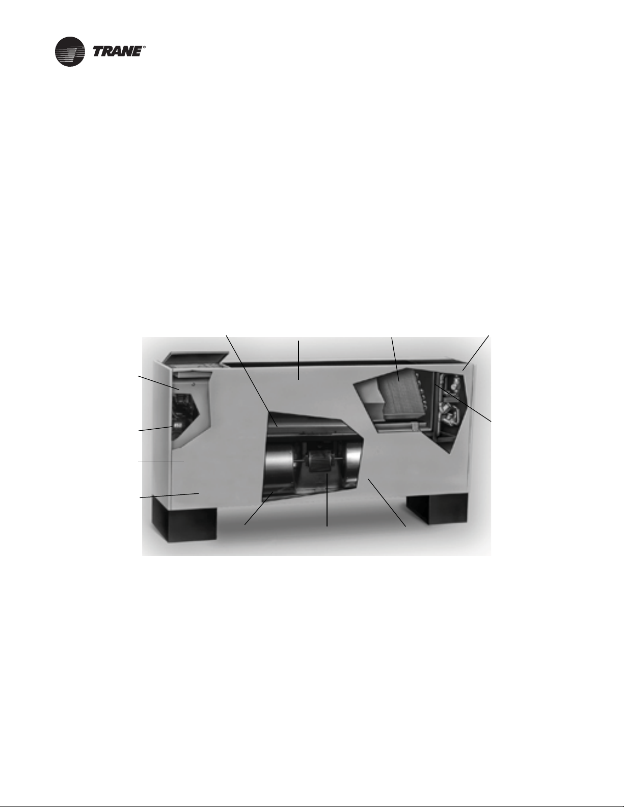
General Information
Smaller unit footprint
Factory-installed and
tested controls
Removable, noncorrosive,
positively-sloped drain pan
Built-in field service
tool with real
language LED
Easy-to-remove
fan assembly
18 gauge steel
construction
Easy filter access
with front panel
removal
Energy efficient
electronically commutated
motor (ECM)
Damper allows up to
100 percent fresh air
Cleanable closedcell insulation
(non-fiberglass)
Factory-assembled, -installed, and
-tested piping package with IAQ
drain pan to collect condensate
Two-, three-, or
four-row coils
Quiet operation
UniTrane™ fan coils and Force Flo™ cabinet heaters are
intended for single zone applications. These units have
load capabilities of 200 to 1200 cfm. See Figure 1 for unit
components.
Fan coils provide cooli ng and heating, and are available as
two-pipe, with or without electric heat (one hydronic
circuit) or four-pipe (two hydronic circuits).
Cabinet heaters are for heating only, and feature two-pipe
hydronic, electric heat only, or steam only.
These units feature a variety of factory mounted piping
packages.
variable speed switch option, which ships separately,
comes with a low voltage (24 volt AC) transformer.
The Tracer® ZN010, ZN510, ZN520, and UC400-B
controllers are included inside the units control box
assembly . These contr olle rs utilize analog signals from a
unit-mounted control device or from a control device
mounted in the occupied space.
The Customer Supplied Terminal Interface (CSTI) option,
includes a 24 volt AC transformer, and an interface
terminal board. Controls provided by an external source
can be tied into the interface terminal board utilizing the
integrated terminal block with 3mm screw connections.
Units with the variable speed fan switch only, are available
with the switch mounted on the unit, or shipped
separately, to be mounted in the occupied space. The
Figure 1. UniTrane fan-coil and Force Flo cabinet heater components (vertical cabinet model shown)
10 UNT-SVX07J-EN
Page 11
Pre-Installation
WARNING
Hazardous Vo ltage w/Capacitors!
Failure to disconnect power and discharge capacitors
before servicing could result in death or serious injury.
Disconnect all electric power, including remote
disconnects and discharge all motor start/run
capacitors before servicing. Follow proper lockout/
tagout procedures to ensure the power cannot be
inadvertently energized. For variable frequency drives
or other energy storing components provided by Trane
or others, refer to the appropriate manuf a cturer’s
literature f or allowable waiting periods for discharge of
capacitors. V e r ify with an appropr iate v oltmeter that all
capacitors have discharged.
For additional information regarding the safe discharge
of capacitors, see PROD-SVB06A-EN
Receiving and Handling
Inspection
Upon delivery, thoroughly inspect all components for any
shipping damage that may have occurred, and confirm
that the shipment is complete. See the Receiving Checklist
section below for detailed instructions.
Note: Delivery cannot be refused. All units are shipped
F.O.B. factory. Trane is not responsible for shipping
damage.
Packaging/Shipping
UniTrane fan coils and Force-Flo cabinet heaters ship in
individual cartons for handling and storage ease.
Field-installed sensors ship separately inside the unit’s
main control panel.
Identification
Each carton has tagging information such as the model
number, sales order number, serial number, unit size,
piping connections, and unit style to help properly locate
the unit in the floor plan. If specified, the un it will ship with
tagging designated by the customer.
Handling
Receiving Checklist
Complete the following checklist immediately after
receiving shipment to detect possible shipping damage.
Check to ensure that the sh ipment is co mplete. Small
components may ship inside the unit or ship
separately. Check the parts list to ensure all materials
are present.
Check all units, components , connections, and piping.
Check fan wheel for free rotation by spinning
manually. Chec k all doors, latches and hinges. Inspect
interior of each unit or section. Inspect coils for
damage to fin surface and coil connections. Check for
rattles, bent corners, or other visible indications of
shipping damage. Tighten loose connections.
If a unit is damaged, make specific notations
concerning the damage on the freight bill. Do not
refuse delivery.
Notify the carrier’s terminal of the damage
immediately by phone and mail. Request an
immediate joint inspection of the damage by the
carrier and consignee.
Notify your Trane sales representative of the damage
and arrange for repair . Do not attempt to repair the unit
without consulting the Trane representative.
Inspect the unit for concealed damage as soon as
possible after delivery. Report concealed damage to
the freight line. It is the receiver’s responsibility to
provide reasonable evidence that concealed damage
did not occur after delivery. Take photos of damaged
material if possible.
Note: Concealed damage must be reported within 15
days of receipt.
Jobsite Storage
This unit is intended for indoor use only. It is the sole
responsibility of the customer to provide the necessary
protection to prevent vandalism and weather protection of
the equipment. Under no circumstance should the unit be
left unprotected from the elements.
T r ane recommends leaving units and acces sories in their
shipping packages/skids for protection and handling ease
until installation. Remove the skid s before placing the unit
in its permanent location.
UNT-SVX07J-EN 11
Microbial Growth! (1 of 2)
Wet interior unit insulation can become an
amplification site for microbial growth (mold), which
could result in odors an d damage t o the equipment and
building materials. If there is evidence of microbial
growth on the int erior insulation, it should be removed
and replaced prior to operating the system.
If indoor storage is not possible, Trane makes the
following recommendations to prevent damage:
NOTICE:
Page 12
Pre-Installation
Note: Keep the equipment on the original wooden blocks/
skid for protection and ease of handling.
• Select a well-drained area, preferably a concrete pad or
blacktop surface.
• Place the unit on a dry surface or raised off the ground
to assure adequate air circulation beneath the unit and
to assure no portion of the unit will contact standing
water at any time.
• Cover the unit securely with a canvas tarp.
NOTICE:
Corrosion!
To prevent corrosion damage or wet stains, use only
canvas tarps to cover air handlers. Plastic tarps can
cause condensation to form in and on the equipment.
• Do not stack units.
• Do not pile other material on the unit.
Site Preparation
• Ensure the installation site can support the total weight
of the unit (see the Dimensions and Weights chapter
for approximate section weights; refer to the unit
submittals for actual weights).
• Allow sufficient space for adequate free air and
necessary service access as shown in the Dimensions
and Weights chapter. Refer to submittals for specific
minimums.
• Allow one and one half fan diameters above the unit
before the discharge ductwork makes any turns.
• Allow room for supply and return piping, ductwork,
electrical connections, and coil removal. Support all
piping and ductwork independently of the unit to
prevent excess noise and vibration.
• Ensure there is adequate height for coil piping and
condensate drain requirements. See “Condensate
Drain Connections,” p. 55.
• Consider coil piping and condensate drain
requirements. Verify condensate line is continuously
pitched one inch per 10 feet of condensate line run to
adequately drain condensate.
• Confirm the floor or foundation is level. For proper unit
operation, the unit must be level (z ero tolerance) in
both horizontal axis.
NOTICE:
Microbial Growth! (2 of 2)
Failure to follow instructions below could result in
odors and damage to the equipment and building
materials.The floor or foundation must be level and the
condensate drain at the proper height for proper coil
drainage and condensat e flow. Standing water and wet
surfaces inside the equipment can become an
amplification site for microbial growth (mold).
• If the unit is to be ceiling mounted, the installer/
contractor must provide threaded suspension rods. All
units must be installed level.
• Vertical recessed/concealed units require wall/ceiling
openings. Refer to submit tal for specific dimensions
before attempting to install.
• Horizontal recessed/concealed units must meet the
requirements of the National Fire Protection
Association (NFPA) Standard 90A or 90B concerning
the use of concealed ceiling spaces as return air
plenums. Refer to the submittal for specific
dimensions of ceiling openings.
• Touch up painted panels if necessary. If panels need
paint, sanding is not necessary. However, clean the
surface of any oil, grease, or dirt residue so the paint
will adhere. Purchase factory approved touch up epoxy
paint from your local Trane Service Parts Center and
apply.
• Units have either right or left hand piping. Reference
piping locations by facing the front of the unit (airflow
discharges from the front). Th e control panel is always
on the end opposite the piping.
• The fan board assembly and main drain pan are easily
removable for cleaning. See the Routine Maintenance
chapter for more details on servicing.
12 UNT-SVX07J-EN
Page 13
Dimensions and Weights
Model A Vertical Concealed
Model K Low Vertical Concealed
Model H Vertical Recessed
36 in.
8.5 in.
both sides
12 in.
both sides
24 in.
3 in.
Model B Vertical Cabinet
Model L Low Vertical Cabinet
Model D Horizontal Cabinet
Model C Horizontal Concealed
Model E Horizontal Recessed
8.5 in.
both sides
12 in.
both sides
28 in.
24 inches
front discharge
28 in.
Service Clearances
Service access is available from the front on vertical units
and from the bottom on horizontal units. Cabinet and
recessed units have removable front or bot tom panels to
Figure 2. Recommende d serv i c e clearances for vertical units
allow access into the unit. See the figures below for
recommended service and operating clearances.
Figure 3. Recommended serv ice clearances for horizontal units
UNT-SVX07J-EN 13
Page 14
Dimensions and Weights
Component Data
Table 1. Fan coil and cabinet heater component data
Unit Size 02 03 04 06 08 10 12
Coil Data
Face Area (ft2) 0.80 0.80 1.10 1.60 2.10 3.20 3.20
L x D x H (in.)
2-Row 15 x 1.7 x 8 15 x 1.7 x 8 20 x 1.7 x 8 29.5 x 1.7 x 8 38 x 1.7 x 8 57 x 1.7 x 8 57 x 1.7 x 8
3-Row 15 x 2.6 x 8 15 x 2.6 x 8 20 x 2.6 x 8 29.5 x 2.6 x 8 38 x 2.6 x 8 57 x 2.6 x 8 57 x 2.6 x 8
4-Row 15 x 3.5 x 8 15 x 3.5 x 8 20 x 3.5 x 8 29.5 x 3.5 x 8 38 x 3.5 x 8 57 x 3.5 x 8 57 x 3.5 x 8
Volu me (g al .)
1-Row (Heat) 0.06 0.06 0.08 0.11 0.14 0.21 0.21
2-Row 0.120.120.150.220.280.420.42
3-Row 0.18 0.18 0.23 0.33 0.42 0.62 0.62
4-Row 0.240.240.300.440.560.830.83
Refrigerant volume (cubic in.)
3-Row ---- ---- ---- 76.23 97.02 143.22 --- 4-Row ---- ---- ---- ---- ---- ---- 191.73
Fins per inch
2-Row 12121212121212
3-Row 12 12 12 12 12 12 12
3/1-Row high capacity 16 16 16 16 16 16 16
4-Row 12121212121212
Reheat Coil Data (1-Row), Standard, or High-Capacity
Hot Water or Steam
Face Area (ft2) 0.60 0.60 0.80 1.20 1.60 2.40 2.40
L x D x H (in.) 15 x 1.5 x 6 15 x 1.5 x 6 20 x 1.5 x 6 29.5 x 1.5 x 6 38 x 1.5 x 6 57 x 1.5 x 6 57 x 1.5 x 6
Volu me (g al .) 0.12 0.12 0.15 0.22 0.28 0.42 0.42
Standard Capacity
in.
High-Capacity Fins/in. 12 12 12 12 12 12 12
Fan/Motor Data
Fan Quantity 1 1 1 2 2 3 3
Size — Dia x Width (in.) 6.31 x 4 6.31 x 6.5 6.31 x 7.5 6.31 x 6.5 6.31 x 7.5 (1) 6.31 x 7.5 6.31 x 7.5
Size — Dia x Width (in.) (2) 6.31 x 6.5
Motor Quantity 1111122
Filter Data
1-in. Throwaway and Pleated Media
Quantity 1 1 1 1 1 1 1
Size (in.) 8-7/8 x 19-1/8 8-7/8 x 19-1/8 8-7/8 x 24-1/8 8-7/8 x 33-5/8 8-7/8 x 42-1/8 8-7/8 x 61-1/8 8-7/8 x 61-1/8
1-in. Fresh Air Filter (only on cabinet styles D, E, and H with bottom return and fresh air opening)
Quantity 1111111
Size (in.) 5-1/2 x 19-1/8 5-1/2 x 19-1/8 5-1/2 x 24-1/8 5-1/2 x 33-5/8 5-/2 x 42-1/8 5-1/2 x 61-1/8 5-1/2 x 61-1/8
(a) Standard and high-capacity reheat coils share the same component data except that standard capacity reheat coils have 4 fins/in. while high-capacity
reheat coils have 12 fins/in
(a)
Fins/
4444444
1
Table 2. Low vertical fan coil component data
Unit Size 03 04 06
Coil Data
Face Area (ft2) 1.10 1.60 2.10
L x D x H (in.)
2-Row 20 x 1.7 x 8 29.5 x 1.7 x 8 38 x 1.7 x 8
3-Row 20 x 2.6 x 8 29.5 x 2.6 x 8 38 x 2.6 x 8
Volu me (g al .)
1-Row (Heat) 0.08 0.11 0.14
2-Row 0.15 0.22 0.28
3-Row 0.230.330.42
Fins per inch
2-Row 121212
3-Row 12 12 12
Fan/Motor Data
Fan Quantity 1 1 1
Size — Dia x Width (in.) 5.00 x 23.00 5.00 x 32.00 5.00x 41.00
Motor Quantity 1 1 1
Filter Data
1-in. Throwaway
Quantity 111
Size — in. 8-7/8 x 24-1/8 8-7/8 x 33-5/8 8-7/8 x 42-1/8
Note: Low vertical model not available for Force Flo cabinet heaters.
14 UNT-SVX07J-EN
Page 15
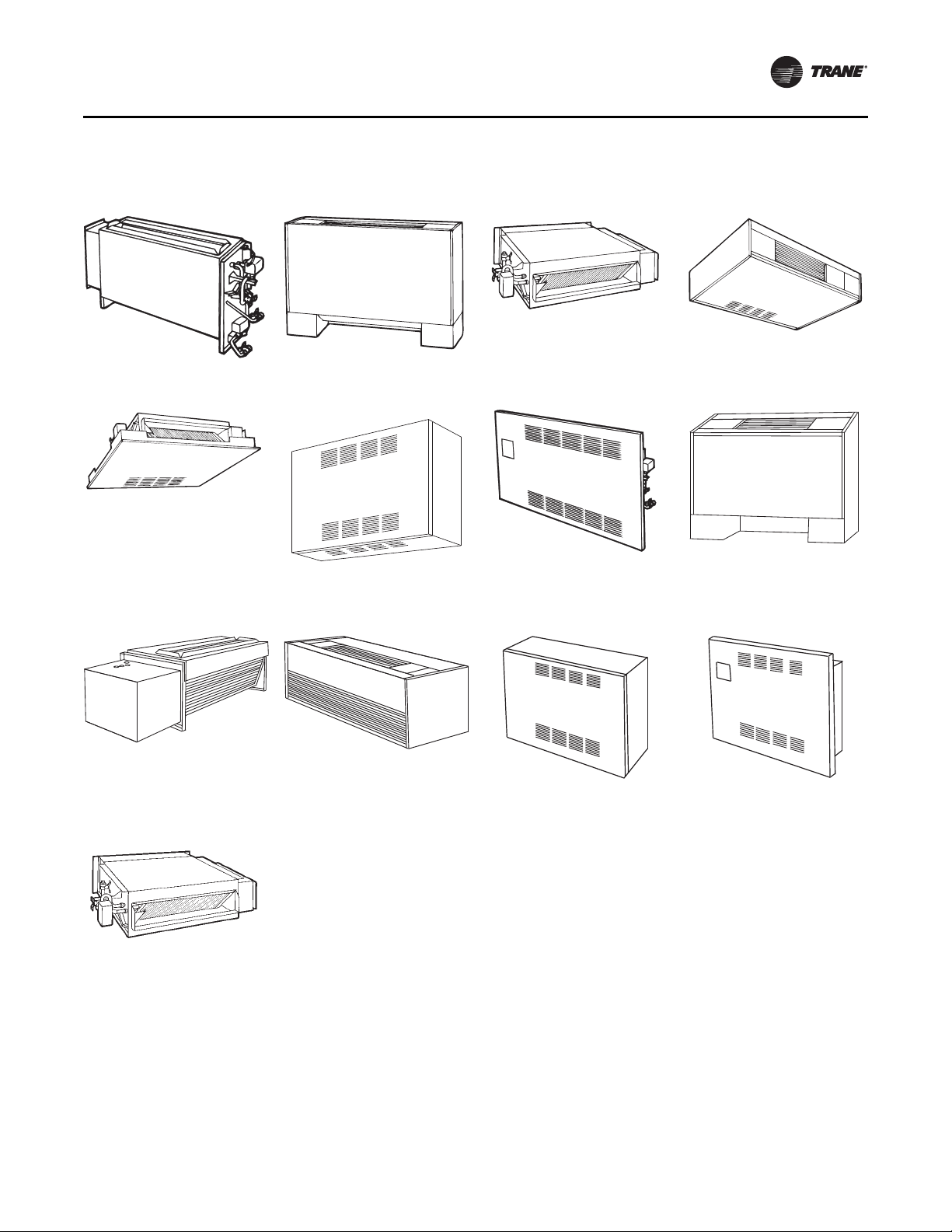
Available Models
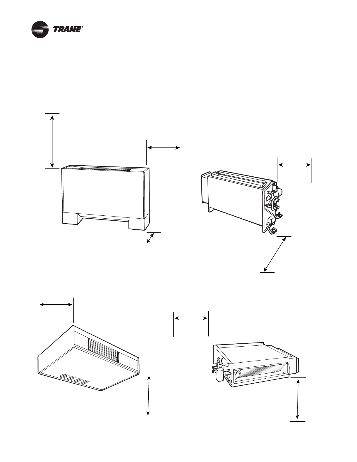
Figure 4. Available UniTrane fan coils and Force Flo cabinet heaters
Dimensions and Weights
Model A:
Vertical Concealed
Model E:
Horizontal Recessed
Model K:
Low Vertical Concealed
Model B:
Vertical Cabinet
Model F:
Wall Hung Cabinet
(Force-Flo units only)
Model L:
Low Vertical Cabinet
Model C:
Horizontal Concealed
Model H:
Vertical Recessed
Model M:
Inverted Vertical Cabinet
(Force-Flo units only)
Model D:
Horizontal Cabinet
Model J:
Vertical Slope Top Cabinet
Model N:
Inverted Vertical Recessed
(Force-Flo units only)
Model P:
Compact Concealed
UNT-SVX07J-EN 15
Page 16

Dimensions and Weights
Top V i e w
C
1 3/4 in. 1 3/4 in.
3 3/8 in.
5 5/16 in.
D
1 in.
1 in.
Top Outlet
Duct Collar
Bottom View
Front View
RH Piping
Side View
Front View
LH Piping
Power
wiring
bottom
only
Power
wiring
bottom
and side
Electric heat only Non-electric heat only
1 3/32 in. KO
7/8 in. KO
7/8 in. KO
6 1/2 in.
Back
Front
1 3/8 in.
2 7/8 in.
Front
1 in.
2 5/8 in.
Detail A Detail B
Back
6 1/4 in.
10 1/16 in.
Air
Flow
Secondary drain
connection for
3/8 in. ID tube
Main drain
connection for
7/8 in. OD copper
tube and clamp
5 7/16 in.
1 9/16 in.
10 1/16 in.
Coil connections
Auxiliary
drain pan
1 1/8 in.
Control
box
Aux box ((EH only)
Junction box
(non EH only)
Filters
3/4 in.
(2) 5/8 in. Bolt hole
7/8 in. KO
Control wiring
Control
box
Junction box
(non EH only)
Auxiliary
control box
(electric heat only)
10 in.
6 7/8 in.
See Detail A and B
for Field power
connnections
6 15/16 in. E
A
6 7/16 in.
9/16 in.
4 7/16 in.
Front inlet
open
4 1/2 in.
7 in.
15 1/2 in.
26 1/4 in.
1 5/8 in.
1 in. duct collar
(4) 5/8 in. dia. keyslot
hanger holes
3/4 in.
1 3/4 in.1 3/4 in.
B
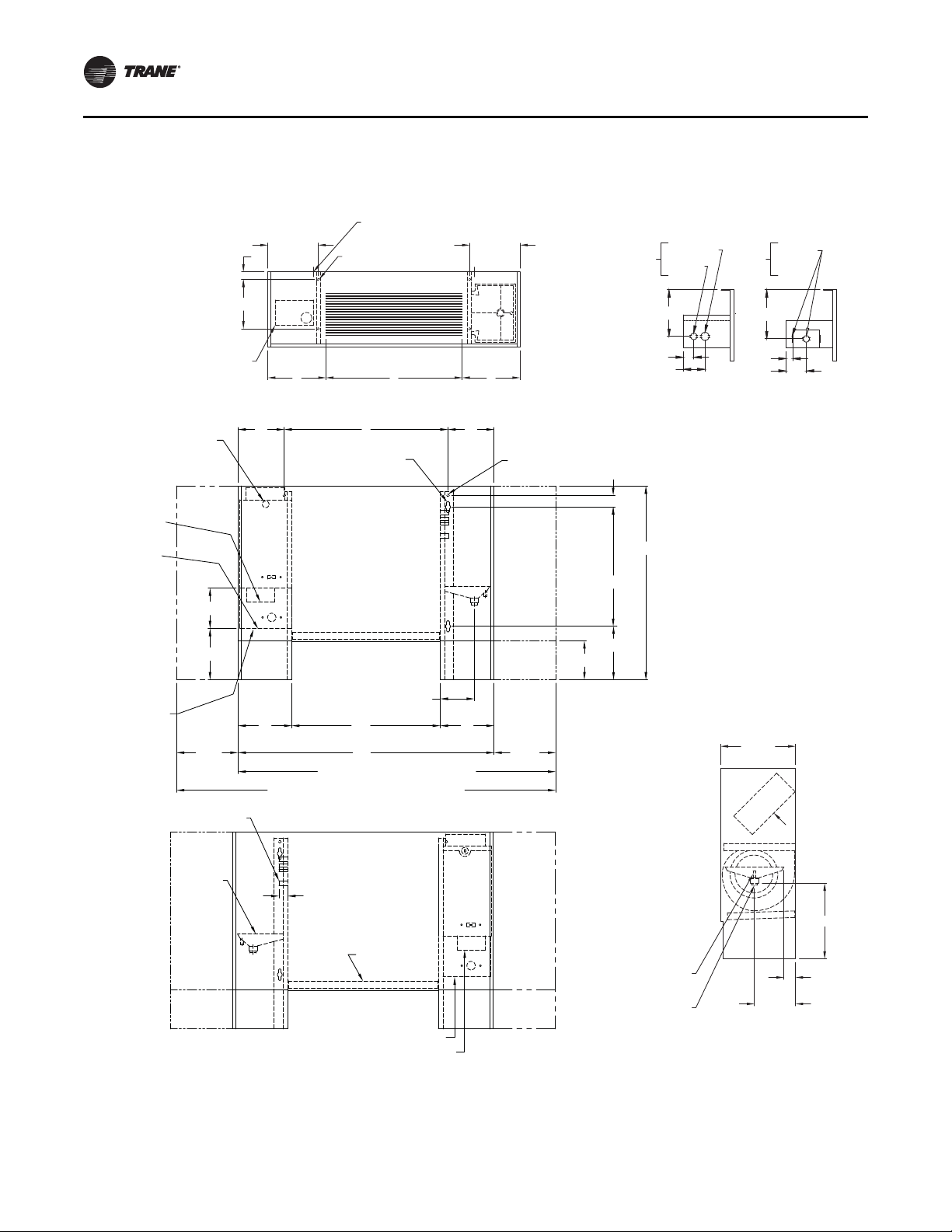
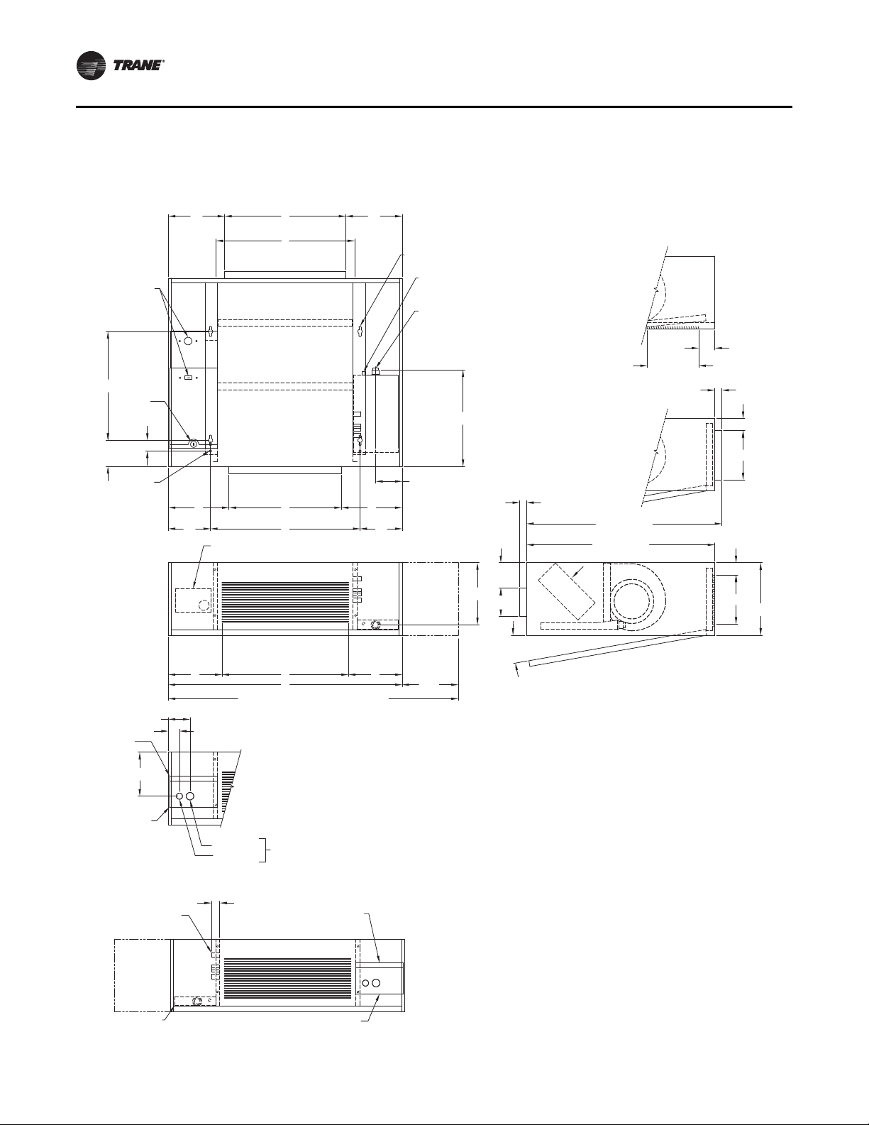
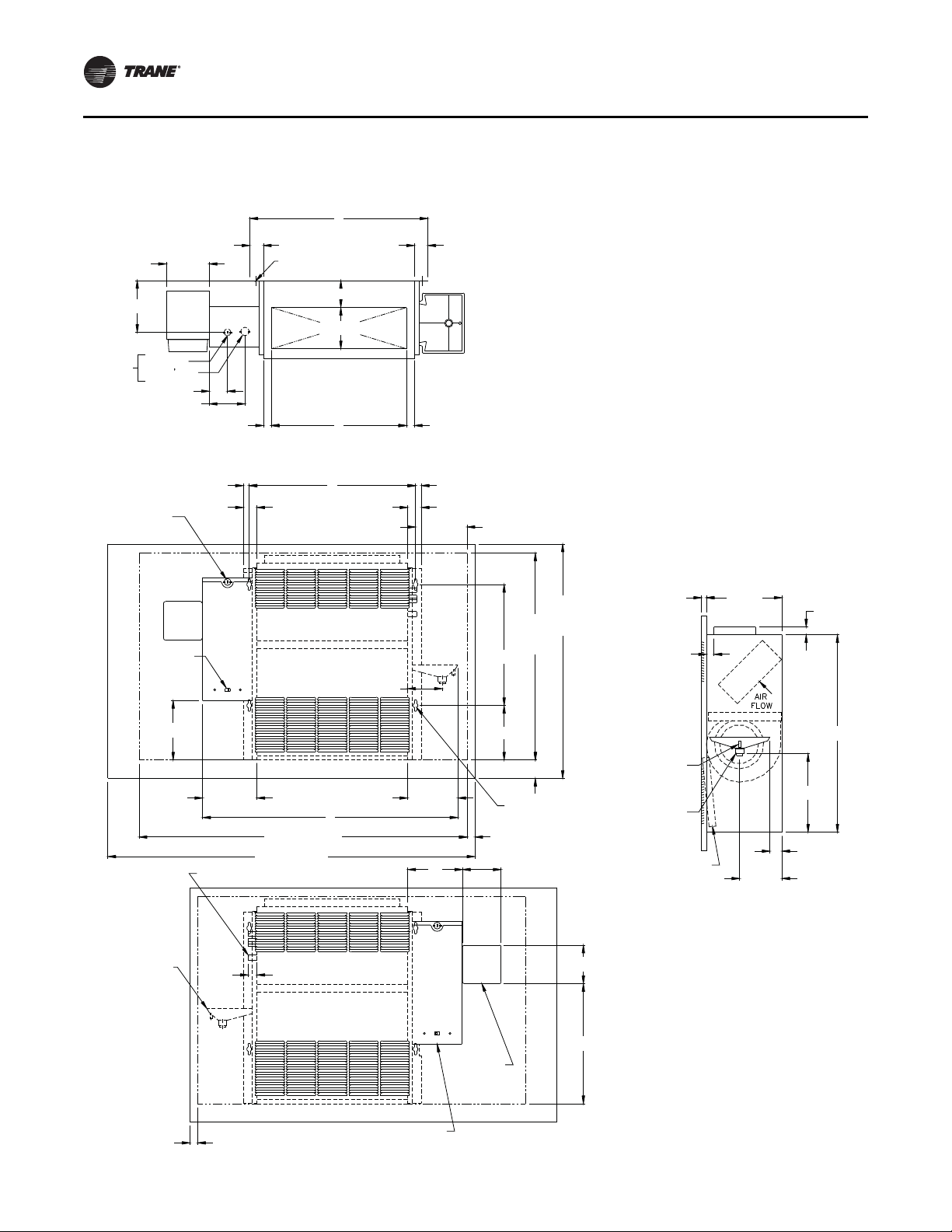
Model A Vertical Concealed
Figure 5. Model A Vertical Concealed
16 UNT-SVX07J-EN
Page 17

Dimensions and Weights
Ta ble 3. Model A Vertical concealed unit dimensions (inches)
Unit Size 200-300 400 600 800 1000-1200
No. Fans1122 3
No. Motors 1 1 1 1 2
A 32 11/16 37 11/16 47 3/16 55 11/16 74 11/16
B 21 5/16 26 5/16 35 13/16 44 5/16 63 5/16
C 22 13/16 27 13/16 37 5/16 45 13/16 64 13/16
D 17 5/16 22 5/16 2’-7 13/16 40 5/16 59 5/16
E 19 5/16 24 5/16 33 13/16 42 5/16 61 5/16
Notes: Coil connections are always on the drain pan side and opposite the control box. Coil connections are 5/8-in. O.D. sweat. See the Coil Connections
section for locations. All duct collar dimensions are to the outside of the collar. See the Fresh Air Openings Locations section for dimensions.
UNT-SVX07J-EN 17
Page 18
Dimensions and Weights
Top View
(4) 5/8 in dia keyslot
hanger holes
(4) Unit leveling devices
(optional)
6 5/8 in.
1 in.
6 5/8 in.
6 1/2 in.
Unit control
top
Top outlet quadrifuser
or bar grille
CD
C
(2) 5/8 in. bolt holes
6 in.
6 in.B
(4) 5/8 in. dia keyslot
hanger holes
7/8 in. KO
Control
wiring
Front View
RH Piping
Auxiliary
control box
optional
5 1/4 in.
6 11/16 in.
Front inlet
open or bar grille
4 7/16 in.
7 in.
E
A
7 in.
8 in.
Control
box
F Optional extended end pocket
Front View
LH Piping
Coil connections
Auxiliary
drain pan
1 1/8 in.
Filters
Control
box
1 5/8 in.
25 3/16 in.
15 1/2 in.
6 15/16 in.
5 1/16 in.
Secondary drain
connection for
3/8 in. ID tube
Main drain connection
for 7/8 in. OD copper
tube and clamp
5 7/16 in.
1 9/16 in.
10 in.
Air
flow
9 7/8 in.
Side
View
Power
wiring
bottom
only
2 7/8 in.
1 3/8 in.
7/8 in.
KO
1 3/32 in.
KO
Bottom View
Power
wiring
bottom
and side
7/8 in.
KO
6 1/4 in.
6 1/2 in.
Back
Front
1 in.
2 5/8 in.
Front
Back
DETAIL A
Electric heat only
DETAIL B
Non-electric heat only
G Optional double extended end pocket
8 in.
See Detail A
and Detail B
for field power
connections
Junction box
(non-EH only)
Auxiliary box (EH only)
Junction box (Non-EH only)
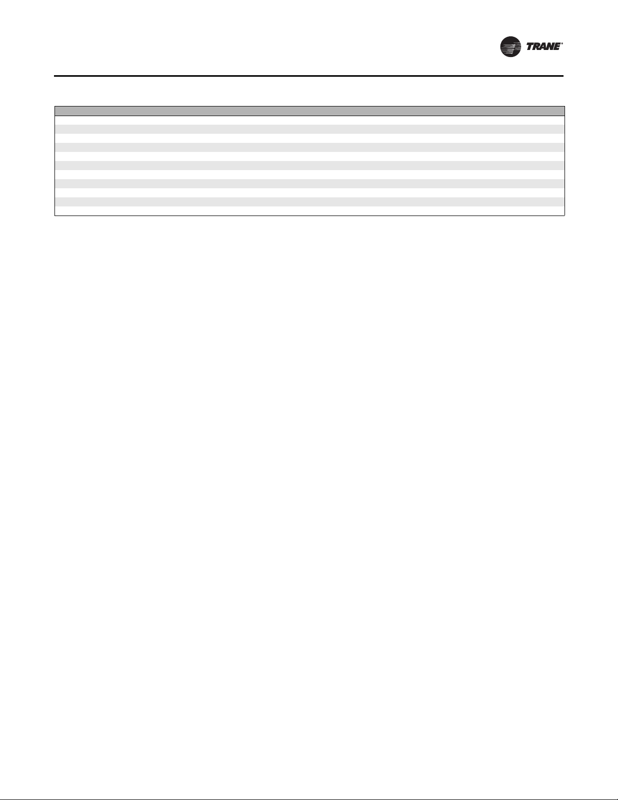
Model B Vertical Cabinet
Figure 6. Model B vertical cabinet
18 UNT-SVX07J-EN
Page 19
Dimensions and Weights
Table 4. Model B Vertical cabinet unit dimensions (inches)
Unit Size 200-300 400 600 800 1000-1200
No. Fans1122 3
No. Motors 1 1 1 1 2
A 33 5/16 38 5/16 47 13/16 56 5/16 75 5/16
B 21 5/16 26 5/16 35 13/16 44 5/16 63 5/16
C 7 5/8 7 1/8 8 7/8 7 1/8 7 5/8
D 18 24 30 42 60
E 19 5/16 24 5/16 33 13/16 42 5/16 61 5/16
F 41 5/16 46 5/16 55 13/16 64 5/16 83 5/16
G 49 5/16 54 5/16 63 13/16 72 5/16 n/a
Notes: Coil connections are always on the drain pan side and opposite the control box. Coil connections are 5/8-in. O.D. sweat. See the Coil Connections
section for locations. All duct collar dimensions are to the outside of the collar. See the Fresh Air Openings Locations section for dimensions.
UNT-SVX07J-EN 19
Page 20
Dimensions and Weights
Top V i e w
2 5/16 in.
E
Back inlet duct collar
9/16 in.
9/16 in.
Optional
disconnect
switch
Aux
box
5 1/4 in.
15 1/2 in.
7/8 in. KO
control
wiring
1 5/8 in.
3 1/4 in.
2 in.
1 3/4 in.
1 3/4 in.
2 5/16 in.
3 1/4 in.
(4) 5/8 in. dia keyslot
hanger holes
Secondary drain connection
for 3/8 in. ID tube
Main drain connection
for 7/8 in. OD copper
tube and clamp
Control
box
(2) 5/8 in. bolt holes
3/4 in. 3/4 in.
Front View
RH Piping
6 15/16 in.
B
C
D
1 11/16 in. 1 11/16 in.
6 3/8 in.
Aux box
optional
6 1/4 in.
Control box
1 3/8 in.
2 7/8 in.
1 3/32 in. KO
7/8 in. KO
Power
wiring
bottom
only
A
2 7/16 in.
8 7/8 in.
5 5/16 in.
Front outlet
duct collar
Front View
LH Piping
1 1/8 in.
Aux box optional
Control box
Auxiliary
drain pan
Coil connections
26 3/4 in.
4 7/8 in. x F
Bottom inlet
open
10 1/16 in.
Filters
Air
flow
1 in. duct collar
27 3/16 in.
Back duct collar
5/8 in.
Filter door used with
back duct collar only
Back inlet duct collar
14 1/8 in.
6 1/8 in.
5/8 in.
1 in. duct collar
Side View
Inlet Options
Model C Horizontal Concealed
Figure 7. Model C Horizontal concealed unit
Table 5. Model C Horizontal concealed unit dimensions (inches)
Unit Size 200-300 400 600 800 1000-1200
No. Fans1122 3
No.Motors 1 1 1 1 2
A 32 11/16 37 11/16 47 3/16 55 11/16 74 11/16
B 21 5/16 26 5/16 35 13/16 44 5/16 63 5/16
Notes: Coil connections are always on the drain pan side and opposite the control box. Coil connections are 5/8-in. O.D. sweat. See the Coil Connections
section for locations. All duct collar dimensions are to the outside of the collar. See the Fresh Air Openings Locations section for dimensions.
20 UNT-SVX07J-EN
Page 21

Dimensions and Weights
Table 5. Model C Horizontal concealed unit dimensions (inches)
Unit Size 200-300 400 600 800 1000-1200
C 22 13/16 27 13/16 37 5/16 45 13/16 64 13/16
D 19 3/8 24 3/8 33 7/8 42 3/8 61 3/8
E 18 1/8 23 1/8 32 5/8 41 1/8 60 1/8
F 19 5/16 24 5/16 33 13/16 42 5/16 61 5/16
Notes: Coil connections are always on the drain pan side and opposite the control box. Coil connections are 5/8-in. O.D. sweat. See the Coil Connections
section for locations. All duct collar dimensions are to the outside of the collar. See the Fresh Air Openings Locations section for dimensions.
UNT-SVX07J-EN 21
Page 22
Top View
E
Back inlet duct collar
8 in. 8 in.
J
Back and bottom
inlet louvers
Optional
disconnect
switch
Aux
box
Control
box
(4) 5/8 in. dia keyslot
hanger holes
Secondary drain
connection for
3/8 in. ID tube
Main drain connection
for 7/8 in. OD copper
tube and clamp
15 1/2 in.
7/8 in.
KO control
wiring
(2) 5/8 in.
bolt holes
Front View
RH Piping
Unit control
front
Front outlet
duct collar (optional)
H
B
G
6 in.
G
6 in.
3 3/4 in.
13 3/4 in.
3 3/4 in.
1 5/8 in.
Front outlet
quadrifuser or bar grille
C
D
C
A
8 in.
F Optional extended end pocket
2 7/8 in.
1 3/8 in.
Aux box opt.
6 1/4 in.
Control box
1 3/32 in.
KO
7/8 in. KO
Power
wiring
bottom
only
Front View
LH Piping
Coil connections
1 1/8 in.
Aux Box
optional
Control boxAuxiliary
drain pan
Filters
2 1/4 in.
Bottom inlet
louvers
7 5/16 in.
1 in. duct
collar
Side View
Inlet and outlet
options
1 3/4 in.
7 in.
Filters
Back inlet
duct collar
1 in. front outlet
duct collar
27 13/16 in.
26 13/16 in.
1 3/4 in.
7 in.
10 5/16 in.
Back inlet
louvers
Bottom access panel - all units
90° to fully open
8 7/8 in.
3 5/8 in.
4 in.
Air
flow
Filters
Dimensions and Weights
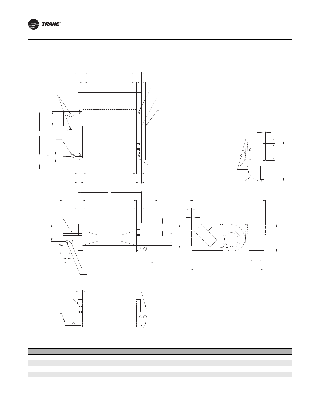
Model D Horizontal Cabinet
Figure 8. Model D Horizontal Cabinet
22 UNT-SVX07J-EN
Page 23
Dimensions and Weights
Table 6. Model D Horizontal cabinet dimensions (inches)
Unit Size 200-300 400 600 800 1000-1200
No. of Fans 1 1 2 2 3
No. of Motors 1 1 1 1 2
A 33 5/16 38 5/16 47 3/16 56 5/16 75 5/16
B 21 5/16 26 5/16 35 13/16 44 5/16 63 5/16
C 7 5/8 7 1/8 8 7/8 7 1/8 7 5/8
D 18 24 30 42 60
E 17 1/4 22 1/4 19 3/4 40 1/4 40 1/4
F 41 1/4 46 5/16 55 3/16 64 5/16 83 5/16
G 8 5/8 8 1/8 9 7/8 8 1/8 8 5/8
H 16 22 28 40 58
Notes: Coil connections are always on the drain pan side and opposite the control box. Coil connections are 5/8-in. O.D. sweat. See the Coil Connections
J 19 3/4 23 3/4 31 3/4 39 3/4 59 3/4
section for locations. All duct collar dimensions are to the outside of the collar. See the Fresh Air Openings Locations section for dimensions.
UNT-SVX07J-EN 23
Page 24
Dimensions and Weights
Top View
8 13/16 in.
(4) 5/8 in. dia
keyslot hanger holes
Optional
disconnect
switch
5 1/4 in.
Aux
box
3 1/4 in.
15 1/2 in.
Control
box
E
Back inlet duct collar
H
Bottom inlet louvers
8 13/16 in.
1 1/2 in.
3/4 in.
29 7/8 in.
1 5/8 in.
5 5/16 in.
2 in.
7/8 in. KO
control wiring
1 11/16 in.
3/4 in.
3/4 in.
1 3/4 in.
1 3/4 in.
3/4 in.
B
F Access Panel
G Ceiling opening
Secondary drain
connection for
3/8 in. ID tube
Main drain
connection for
7/8 in. OD copper
tube and clamp
28 3/8 in.
ceiling
opening
26 7/8 in.
bottom
access panel
Side View
Inlet Options
15 5/16 in.
Front View
RH Piping
1 1/2 in.
3/4 in.
1 11/16 in.
3/4 in.
2 7/8 in.
1 3/8 in.
Aux box
optional
6 1/4 in.
Control
box
8 3/16 in.
1 7/16 in.
7/8 in. KO
1 3/32 in. KO
Power wiring
back only
1 1/8 in.
Coil connections
Auxiliary
drain pan
Front View
LH Piping
Ctrl
box
A
C
1 11/16 in.1 11/16 in.
(4) 5/8 in. dia keyslot
hanger holes
2 7/16 in.
8 7/8 in.
5 5/16 in.
8 3/16 in.
1 7/16 in.
Bottom access panel - all units
90° to
full open
Back inlet
duct collar
1 7/16 in.
1 1/8 in.
D
Front outlet
duct collar
1 in. duct collar
27 3/16 in.
back duct collar
26 3/16 in.
bottom inlet louvers
2 3/16 in.
1 in. duct collar
5/8 in.
6 1/8 in.
Filters
Air
flow
7 5/16 in.
Bottom inlet
louvers
3 13/16 in.
11 1/2 in. - 12 3/4 in.
bottom inlet
10 1/2 in. - 12 1/2 in.
back inlet
Filters
Model E Horizontal Recessed
Figure 9. Model E Horizontal Recessed
24 UNT-SVX07J-EN
Page 25

Dimensions and Weights
Ta ble 7. Model E Horizontal recessed unit dimensions (inches)
Unit Size 200-300 400 600 800 1000-1200
No. Fans 1 1 2 2 3
No. Motors 1 1 1 1 2
A 35 13/16 40 13/16 50 5/16 58 13/16 77 13/16
B 21 5/16 26 5/16 35 13/16 44 5/16 63 5/16
C 22 13/16 27 13/16 37 5/16 45 13/16 64 13/16
D 19 3/8 24 3/8 33 7/8 42 3/8 61 3/8
E 18 1/8 23 1/8 32 5/8 41 1/8 60 1/8
F 32 7/16 37 7/16 46 15/16 55 7/16 74 7/16
G 34 5/16 39 5/16 48 13/16 57 5/16 76 5/16
H 19 3/4 23 3/4 31 3/4 39 3/4 59 3/4
Notes: Coil connections are always on the drain pan side and opposite the control box. Coil connections are 5/8-in. O.D. sweat. See the Coil Connections
section for locations. All duct collar dimensions are to the outside of the collar. See the Fresh Air Openings Locations section for dimensions.
UNT-SVX07J-EN 25
Page 26
Dimensions and Weights
Top V i e w
Bottom View
Front View
RH Piping
Side View
Front View
LH Piping
Unit control
top
Top outlet quadrifuser
or bar grille
C
D
C
Detail A Detail B
Power
wiring
bottom
only
1 3/32 in. KO
7/8 in. KO
Power
wiring
bottom
and side
7/8 in. KO
Back
Front
Back
Front
6 1/4 in.
1 3/8 in.
2 7/8 in.
6 1/2 in.
1 in.
2 5/8 in.
Electrical heat only Non electric heat only
10 5/16 in.
Air
flow
1 1/4 in.
4 in.
Bottom inlet
louvers
6 in. B
6 in.
7 in.
E
7 in.
(4) 5/8 in. dia Keyslot
hanger holes
(2) 5/8 in.
Bolt holes
Front outlet louvers
(optional)
Front inlet louvers
Junction box
(non EH only)
Auxiliary control box
(electric heat only)
5 1/4 in.
Control
box
8 5/16 in.
See Detail A and B
for Field power
connections
A
F
Bottom and front
inlet and outlet louvers
8 9/16 in.
26 13/16 in.
15 1/2 in.
1 5/8 in.
Coil connections
7/8 in. KO
Control wiring
Control
box
1 1/8 in.
Filters
Auxiliary box (EH only)
Junction Box (non EH only)
Model F Vertical Wall Hung Cabinet
Force Flo Units Only
Figure 10. Model F Vertical Wall Hung Cabinet (Force Flo only)
26 UNT-SVX07J-EN
Page 27

Dimensions and Weights
Table 8. Model F Vertical wall hung cabinet unit dimensio ns (inches)
Unit Size 200-300 400 600 800 1000-1200
No. Fans 1 1 2 2 3
No. Motors 1 1 1 1 2
A 33 5/16 38 5/16 47 13/16 56 5/16 75 5/16
B 21 5/16 26 5/16 35 13/16 44 5/16 63 5/16
C 7 5/8 7 1/8 8 7/8 7 1/8 7 5/8
D 18 24 30 42 60
E 19 5/16 24 5/16 33 13/16 42 5/16 61 5/16
F 19 3/4 23 3/4 31 3/4 39 3/4 59 3/4
Notes: Coil connections are always on the drain pan side and opposite the control box. Coil connections are 5/8-in. O.D. sweat. See the Coil Connections
section for locations. All duct collar dimensions are to the outside of the collar. See the Fresh Air Openings Locations section for dimensions.
UNT-SVX07J-EN 27
Page 28
Dimensions and Weights
Top V i e w
Front View
RH Piping
Front View
LH Piping
Side
View
5 1/2 in.
C
1 3/4 in. 1 3/4 in.
(4) 5/8 in. dia keyslot
hanger holes
3 7/16 in.
5 5/16 in.
Top outlet
duct collar (optional)
6 5/8 in.
Power
wiring
bottom
only
7/8 in. KO
1 3/32 in. KO
2 5/16 in.
4 9/16 in.
1 in.
D
1 in.
3/4 in.
1 3/4 in.
3/4 in.
1 3/4 in.
6 5/8 in.
7/8 in. KO
control wiring
Front outlet louvers
Control
box
Optional
disconnect
switch
7 5/8 in.
4 7/16 in.
6 15/16 in.
Front inlet louvers
6 7/16 in.
A
H Wall opening
F
Front
panel
J
Wall
opening
15 1/2 in.
7 in.
G
B
(4) 5/8 in. dia keyslot
hanger holes
1 in.
4 15/16 in.
7 in.
E Front panel
Coil connections
Auxiliary
drain pan
1 1/8 in.
1 in.
Wall opening
Power wiring 7/8 in.
or 1 3/32 in. KOs
Front
control
access
(optional)
15 3/8 in.
4 15/16 in.
Control
box
5/8 in.
1 in. duct
collar
25 1/4 in.
10 1/16 in.
1 9/16 in.
5 7/16 in.
Filters
Main drain connection
for 7/8 in. OD copper
tube and clamp
Secondary
drain connection
for 3/8 in. ID tube
9 3/4 in.
1 in.
Model H Vertical Recessed
Figure 11. Model H Vertical Recessed
28 UNT-SVX07J-EN
Page 29
Dimensions and Weights
Ta ble 9. Model H Vertical Recessed Unit
Unit Size 200-300 400 600 800 1000-1200
No. Fans 1 1 2 2 3
No. Motors 1 1 1 1 2
A 32 11/16 37 11/16 47 3/16 55 11/16 74 11/16
B 21 5/16 26 5/16 35 13/16 44 5/16 63 5/16
C 22 13/16 27 13/16 37 5/16 45 13/16 64 13/16
D 17 5/16 22 5/16 31 13/16 40 5/16 59 5/16
E 47 51 63 65 1/2 89 1/2
F 30 30 30 33 1/2 33 1/2
G 2 3/8 2 3/8 2 3/8 4 1/8 4 1/8
H 42 48 57 63 87
J 26 1/2 26 1/2 26 1/2 27 1/2 27 1/2
Notes: Coil connections are always on the drain pan side and opposite the control box. Coil connections are 5/8-in. O.D. sweat. See the Coil Connections
section for locations. All duct collar dimensions are to the outside of the collar. See the Fresh Air Openings Locations section for dimensions.
UNT-SVX07J-EN 29
Page 30
Dimensions and Weights
Top V i e w
6 5/8 in.
1 1/16 in.
6 1/2 in.
(4) Unit leveling devices
(optional)
6 5/8 in.
2 7/8 in.
1 3/8 in. KO
6 1/4 in.
Power
wiring
bottom
only
7/8 in. KO
1 3/32 in. KO
Unit control
top
C
D
Top outlet
Quadrifuser or bar grille
C
Front View
LH Piping
Coil connections
Auxiliary
drain pan
1 1/8 in.
Filters
Control
box
Aux
box
Power wiring 7/8 in.
or 1 3/32 in. KOs
10 in.
Side
View
Air
flow
24 7/8 in.
Secondary drain
connection
for 3/8 in ID tube
Main drain connection
for 7/8 in. OD copper
tube and clamp
5 7/16 in.
1 9/16 in.
10 in.
Bottom View
Back
Back
Front
Front
Power
wiring
bottom
and side
7/8 in. KO
6 1/2 in.
1 in.
2 5/8 in.
DETAIL A
Electric heat only
DETAIL B
Non-electric heat only
Front View
RH Piping
6 in. B
6 in.
Auxiliary
control box
(electric heat only)
5 1/4 in.
6 11/16 in.
Control
box
Front inlet
open or bar grille
7 in.
E
A
7 in.
8 in.
F Optional extended end pocket
(4) 5/8 in. dia keyslot
hanger holes
(2) 5/8 in. bolt holes
15 1/2 in.
6 15/16 in.
5 1/16 in.
1 5/8 in.
Front outlet louvers
(optional)
8 in.
See Detail A
and Detail B
for field power
connections
G Optional double extended end pocket
Junction box
(non-electric heat only)
Model J Vertical Slope Top Cabinet
Figure 12. Model J Vertical Slope Top
30 UNT-SVX07J-EN
Page 31

Dimensions and Weights
Table 10. Model J Vertical slope top cabinet unit dimensions
Unit Size 200-300 400 600 800 1000-1200
No. Fans 1 1 2 2 3
No. Motors 1 1 1 1 2
A 33 5/16 38 5/16 47 13/16 56 5/16 75 5/16
B 21 5/16 26 5/16 35 13/16 44 5/16 63 5/16
C 7 5/8 7 1/8 8 7/8 7 1/8 7 5/8
D 18 24 30 42 60
E 19 5/16 24 5/16 33 13/16 42 5/16 61 5/16
F 41 5/16 46 5/16 55 13/16 64 5/16 81 5/16
G 49 5/16 54 5/16 63 13/16 72 5/16 n/a
Notes: Coil connections are always on the drain pan side and opposite the control box. Coil connections are 5/8-in. O.D. sweat. See the Coil Connections
section for locations. All duct collar dimensions are to the outside of the collar. See the Fresh Air Openings Locations section for dimensions.
UNT-SVX07J-EN 31
Page 32

Dimensions and Weights
Top V i e w
(2) 5/8-in. dia Keyslot
hander holes
C
9 1/4 in.
Power wiring
bottom only
3 in. x 3 in.
opening
8 5/16 in.
1 1/16 in.
D
1 1/16 in.
Top outlet
duct collar
6 1/4 in.
6 in.
11 5/8 in. HR
10 3/4 in. HS
9 5/8 in. CR
8 5/16 in. CS
Side
View
HR
HS
9 3/16 in.
HR
6 7/8 in.
HS
CS
CR
9 3/16 in.
CS
8 11/16 in.
CR
Right hand coil connections
shown. Left hand connection
locations are mirror image.
14 1/2 in.
16 in.
5/8 in.
duct collar
14 9/16 in.
1 15/16 in.
2 in.
Main drain connection
for 7/8 in. OD copper
tube and clamp
14 in.
1 5/16 in.
15 1/8 in.
13 1/4 in.
Filters
Airflow
Front View
RH Piping
7/8 in.
7/8 in. KO
Control wiring
1 13/16 in.
B
1 13/16 in.
7/8 in.
(2) 5/8 in. dia keyslot
hanger holes
3 9/16 in.
7 1/4 in.
3 1/4 in.
6 7/16 in.
A
E
10 3/4 in.
Front inlet
open
Main
power
access
Control
box
12 3/16 in.
9/16 in.
1 1/8 in.
Front View
LH Piping
Coil connections
Auxiliary
drain pan
Control
box
CS Cooling coil supply
CR Cooling coil return
HS Heating coil supply
HR Heating coil return
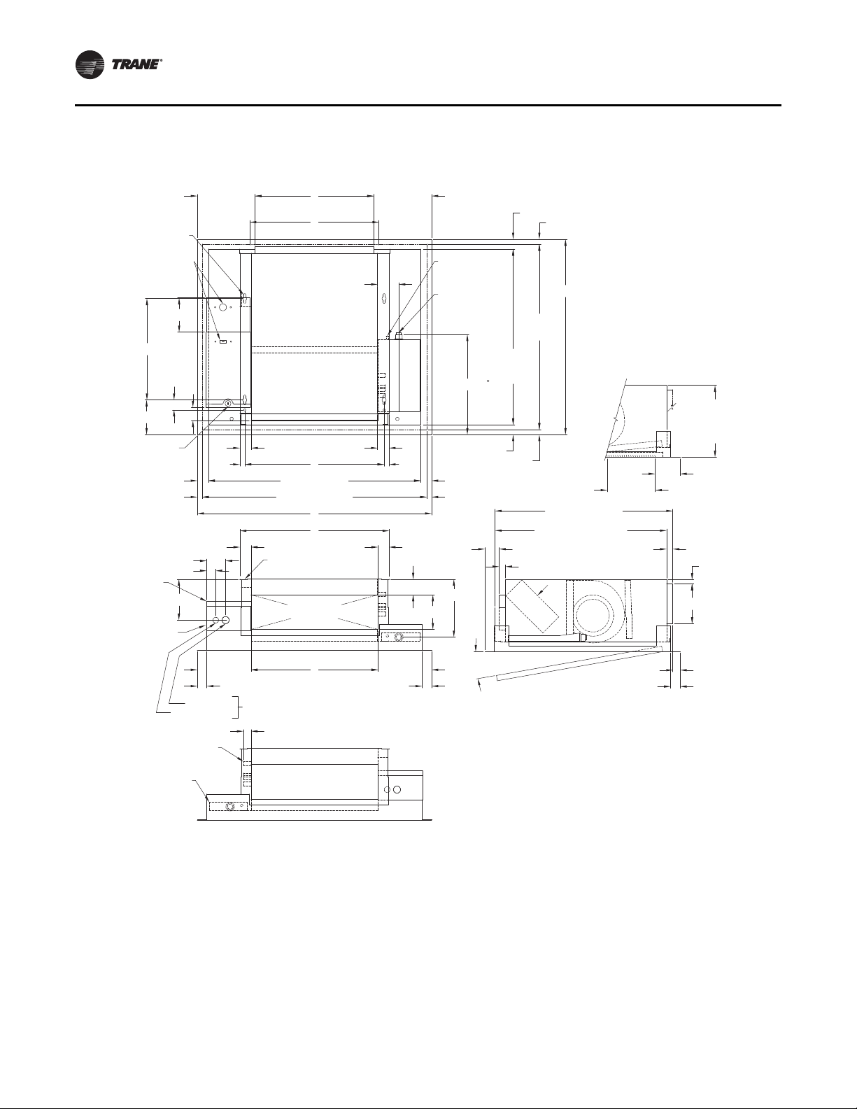
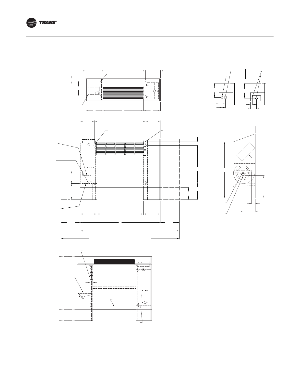
Model K Low Vertical Concealed
Figure 13. Model K Low Vertical Concealed
32 UNT-SVX07J-EN
Page 33

Dimensions and Weights
Table 11. Model K Low vertical concealed unit dimensions (in.) and weights (lb)
Unit Size 03 04 06
A 41-7/16 50-15/16 59-7/16
B 26-1/4 35-3/4 44-1/4
C 27-15/16 36-13/16” 45-15/16
D 22-5/16 31-13/16 40-5/16
E 24-1/4 33-3/4 42-1/4
Operating Weight 109 139 147
Shipping Weight 96 123 131
Notes: Coil connections are always on the drain pan side and opposite the control box. Coil connections are 5/8-in. O.D. sweat. See the Coil Connections
section for locations. All duct collar dimensions are to the outside of the collar. See the Fresh Air Openings Locations section for dimensions.
Serviceability for some components within this unit may require panel or drain pan removal.
UNT-SVX07J-EN 33
Page 34

Dimensions and Weights
11 5/8 in. HR
10 3/4 in. HS
9 5/8 in. CR
8 5/16 in. CS
HR
HS
CS
CR
9 3/16 in.
HR
6 7/8 in.
HS
9 3/16 in.
CS
8 11/16 in.
CR
Right hand coil connections shown.
Left hand connection locations
are mirror image.
HR-heating coil return
HS-heating coil supply
CR-cooling coil return
CS-cooling coil supply
Main drain connection for
7/8 in. OD copper tube and clamp
Air
flow
14 9/16 in.
1 15/16 in.
2 in.
14 1/2 in.
1 5/16 in.
Filters
9 11/16 in.
Power
wiring
bottom
only
7/8 in. KO
6 7/8 in.
1 1/8 in.
Coil connections
Auxiliary
drain pan
Control
box
Front View
LH Piping
Front View
RH Piping
7/8 in.
B
7/8 in.
7/8 in. KO Control wiring
1 13/16 in.
1 13/16 in.
(2) 5/8 in dia Keyslot
hanger holes
Control
box
Main power
access
Bottom of
control box
2 11/16 in.
Front inlet bar grille
3 1/4 in.
6 7/16 in.
11 5/16 in.
E
A
11 5/16 in.
13 3/16 in.
Top V i e w
(2) 5/8 in. dia Keyslot
hanger holes
10 15/16 in.
(4) Unit leveling devixces
(optional)
10 15/16 in.
4 7/16 in.
8 1/2 in.
Unit control
top
C CD
Top outlet quadrifuser
or bar grille
Side View
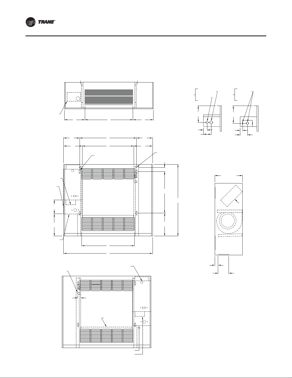
Model L Low Vertical Cabinet
Figure 14. Model L Low vertical cabinet
34 UNT-SVX07J-EN
Page 35

Dimensions and Weights
Ta ble 12. Model L Low vertical cabinet unit dimensions (in.) and weights (lb)
Unit Size 03 04 06
A 46 15/16 56 7/16 64 15/16
B 26 1/4 35 3/4 44 1/4
C 11 7/16 13 5/16 11 7/16
D 24 30 42
E 24 1/4 33 3/4 42 1/4
Operating Weight 125 155 164
Shipping Weight 112 139 148
Notes: Coil connections are always on the drain pan side and opposite the control box. Coil connections are 5/8-in. O.D. sweat. See the Coil Connections
section for locations. All duct collar dimensions are to the outside of the collar. See the Fresh Air Openings Locations section for dimensions.
Serviceability for some components within this unit may require panel or drain pan removal.
UNT-SVX07J-EN 35
Page 36

Dimensions and Weights
Model M Inverted Vertical Cabinet
Force-Flo Unit Only
Figure 15. Model M inverted vertical cabinet (Force-Flo unit only)
Top Vie w
Unit control
top
Front View
RH Piping
See Detail A and B
for Field power connections
7 5/16 in.
5 1/4 in.
Auxiliary control box
(electric heat only)
Junction box
(non electric heat only)
Front View
LH Piping
Top outlet quadrifuser
C
GHG
Control
box
7 1/8 in.
6 in.
or bar grille
D
Front inlet and
outlet louvers
F
Top inlet duct collar
(optional)
Bottom outlet
duct collar (optional)
E
B
A
Junction box (Non EH only)
Auxiliary box (EH only)
C
7 1/8 in.
6 in.
Bottom View
Power
wiring
bottom
only
1 3/8 in.
2 7/8 in.
Side View
Inlet and outlet
(4) 5/8 in. dia Keyslot
hanger holes
15 1/2 in.
1 5/8 in.
3 11/16 in.
(2) 5/8 in. bolt holes
Front
28 3/4 in.
Power
wiring
bottom
and side
6 1/2 in.
1 in.
2 5/8 in.
7/8 in. KO
10 5/16 in.
4 in.
Air
flow
6 in.
1 3/32 in. KO
7/8 in. KO
6 1/4 in.
Detail A Detail B
Electric heat only Non electric heat only
options
BackBack
Front
Top inlet
duct collar
3 11/16 in.
26 13/16 in.
2 5/8 in.
Bottom inlet
duct collar
Filters
Control
box
Coil connections
1 1/8 in.
36 UNT-SVX07J-EN
Page 37

Dimensions and Weights
Ta ble 13. Model M Inverted vertical cabinet unit dimensions (in.) and weights (lb)
Unit Size 02–03 04 06 08 10–12
A 33 5/16 38 5/16 47 13/16 56 5/16 75 5/16
B 21 5/16 26 5/16 35 13/16 44 5/16 63 5/16
C 7 5/8 7 1/8 8 7/8 7 1/8 7 5/8
D 18 24 30 42 60
E 19 5/16 24 5/16 33 13/16 42 5/16 61 5/16
F 19 3/4 23 3/4 31 3/4 39 3/4 59 3/4
Operating Weight 97 125 155 164 218
Shipping Weight 84 112 139 148 200
Notes: Coil connections are always on the drain pan side and opposite the control box. Coil connections are 5/8-in. O.D. sweat. See the Coil Connections
section for locations. All duct collar dimensions are to the outside of the collar. See the Fresh Air Openings Locations section for dimensions.
UNT-SVX07J-EN 37
Page 38

Dimensions and Weights
Top Vie w
Front View
RH Piping
Side View
Front View
LH Piping
Bottom View
9 3/4 in.
5/8 in.
25 1/4 in.
Air
flow
Power
wiring
bottom
only
Power
wiring
bottom
and side
7/8 in. KO
Back
Front
Non electric heat onlyElectric heat only
Detail A Detail B
Back
Front
1 3/8 in.
2 7/8 in.
1 in.
2 5/8 in.
6 1/2 in.
6 1/4 in.
1 3/32 in. KO
7/8 in. KO
1 in. Wall opening
4 15/16 in.7 in.
See Detail A and B
for Field power
connections
4 15/16 in.
15 3/8 in.
Front
control
access
(optional)
1 1/8 in.
Control
box
Coil connections
Filters
3/4 in.
1 3/4 in.
3/4 in.
1 3/4 in.
6 5/8 in.
Auxiliary box
(EH only)
Junction box
(non EH only)
Control
box
7/8 in. KO
Control
wiring
6 15/16 in.
(2) 5/8 in. Bolt holes
A
H Wall opening
E Front panel
1 in.
(4) 5/8 in. dia Keyslot
hanger holes
Front outlet louvers
1 5/8 in.
2 1/8 in.
D
G
Wall
opening
F
Front
panel
15 12 in.
1 3/4 in. 1 3/4 in.
C
5 7/8 in.
Model N Inverted Vertical Recessed
Force-Flo Unit Only
Figure 16. Model N inverted vertical recessed (Force-Flo unit only)
38 UNT-SVX07J-EN
Page 39

Dimensions and Weights
Table 14. Model N Inverted vertical recessed unit dimensions (in.) and weights (lb)
Unit Size 02–03 04 06 08 10–12
Notes: Coil connections are always on the drain pan side and opposite the control box. Coil connections are 5/8-in. O.D. sweat. See the Coil Connections
A 27 7/8 32 7/8 42 3/8 50 7/8 69 7/8
B 21 5/16 26 5/16 35 13/16 44 5/16 63 5/16
C 22 13/16 27 13/16 37 5/16 45 13/16 64 13/16
D 2 3/8 2 3/8 2 3/8 4 1/8 4 1/8
E 47 51 63 65 1/2 89 1/2
F 30 30 30 33 1/2 33 1/2
G 26 1/2 26 1/2 26 1/2 27 1/2 27 1/2
H 42 48” 57 63 87
Operating Weight 78 88 128 139 253
Shipping Weight 68 78 118 129 243
section for locations. All duct collar dimensions are to the outside of the collar. See the Fresh Air Openings Locations section for dimensions.
UNT-SVX07J-EN 39
Page 40

Dimensions and Weights
Top View
Front View
RH Piping
Front View
LH Piping
Side View
Inlet Options
2 5/16 in.
E
Back inlet duct collar
9/16 in. 9/16 in.
Optional
discoonect
switch
15 1/2 in.
7/8 in.
KO control
wiring
3 1/4 in.
2 in.
3/4 in.
1 3/4 in. 1 3/4 in.
B
C
D6 15/16 in.
Control
box
2 5/16 in.
3 1/4 in.
(4) 5/8 in. dia keyslot
hanger holes
Secondary drain
connection for 3/8 in. ID tube
Main drain connection
for 7/8 in. OD copper
tube and clamp
1 in. duct collar
5/8 in.
6 1/8 in.
14 1/8 in.
Back inlet
duct collar
Filter door used with
back duct collar only
Filters
3/4 in.
1 11/16 in. 1 11/16 in.
6 3/8 in.
2 7/16 in.
8 7/8 in.
5 5/16 in.
6/5/8 in.
Control
box
2 5/16 in.
4 9/16 in.
1 3/32 in.
KO
7/8 in. KO
A
Power wiring
bottom only
1 1/8 in.
Coil connections
Auxiliary
drain pan
Control
box
27 3/16 in.
Back duct collar
5/8 in.
1 in. duct collar
Air
flow
10 1/16 in.
4 7/8 in. x F
26 3/4 in.
Bottom
inlet open
Filters
(4) 5/8 in. dia keyslot
hanger holes
Front outlet
duct collar
Mode P Compact Concealed
Figure 17. Model P Compact Concealed
40 UNT-SVX07J-EN
Page 41

Dimensions and Weights
8 3/16 in. RHS
5 5/16 in. CS
4 7/8 in. RHR
4 3/8 in. CR
4 in. HS
2 5/16 in. HR
Dimensions are typical
to vertical unit styles.
Vertical Concealed
Vertical Recessed
(recess panel not shown)
Vertical Cabinet
Vertical Slope
Top
RHS
CS
RHS
CR
HR
HS
CS
RHR
CR
HR
HS
RHR
RHR
RHS
23 1/4 in.
RHR
19 15/16 in.
RHS
18 11/16 in.
HS
20 1/2 in.
HR
20 13/16 in.
CR
21 13/16 in.
CS
Bottom of Vertical Units
CS
CR
HR
HS
Table 15. Compact concealed unit dimensions (in.)
Unit Size 200-300 400 600 800 1000-1200
A 32 11/16 37 11/16 47 3/16 55 11/16 74 11/16
B 21 5/16 26 5/16 35 13/16 44 5/16 63 5/16
C 22 13/16 27 13/16 37 5/16 45 13/16 64 13/16
D 19 3/8 24 3/8 33 7/8 42 3/8 61 3/8
E 18 1/8 23 1/8 32 5/8 41 1/8 60 1/8
F 19 5/16 24 5/16 33 13/16 42 5/16 61 5/16
Notes: Coil connections are always on the drain pan side and opposite the control box. Coil connections are 5/8-in. O.D. sweat. See the Coil Connections
section for locations. All duct collar dimensions are to the outside of the collar. See the Fresh Air Openings Locations section for dimensions.
Coil Connections
Fan Coil Vertical Units
Figure 18. Coil connections for fan coil vertical units
UNT-SVX07J-EN 41
Page 42

Dimensions and Weights
Horizontal Concealed
Horizontal Recessed
(Recess panel not shown)
HR
HS
CR
RHS
CS
RHR
1 in.
7/16 in.
22 3/8 in. CS
21 3/8 in. CR
21 1/16 in. HR
19 5/16 in. HSDimensions are typical
to horizontal unit styles.
5 5/16 in.
CS
4 7/8 in.
RHS
4 3/8 in.
CR
8 3/16 in.
RHS
Horizontal Cabinet
HR
HS
CR
RHR
CS
RHS
20 9/16 in. RHS
23 7/8 in. RHR
2 5/16 in. HR
4 in. HS
Fan Coil Horizontal Units
Figure 19. Coil connections for fan coil horizontal units
42 UNT-SVX07J-EN
Page 43

Force Flo Vertical Units
5 5/16 in. HS
4 3/8 in. HR
5 5/16 in. HS
4 3/8 in. HR
5 3/8 in. HS
4 7/16 in. HR
5 5/16 in. HS
4 3/8 in. HR
23 3/8 in.
HS
22 3/8 in.
HR
20 13/16 in.
HR
21 13/16 in.
HS
HS
HR
HS
HR
HS
HR
HS
HR
Vertical Concealed
Vertical Recessed
(recess panel not shown)
Vertical Cabinet Vertical Slope
Top Cabinet
Vertical Wall
Hung Cabinet
Bottom of
Vertical Units
Figure 20. Coil connections for Force Flo cabinet heater vertical units
Dimensions and Weights
UNT-SVX07J-EN 43
Page 44

Dimensions and Weights
Horizontal Concealed
Horizontal Recessed
(recess panel not shown)
1 in.
4 3/8 in.
HR
5 5/16 in.
HS
7/16 in.
22 3/8 in. HS
21 3/8 in. HR
HR
HS
Horizontal Cabinet
4 3/8 in.
HR
5 5/16 in.
HS
Inverted Vertical
Cabinet
HR
HS
4 7/16 in.
HS
5 7/16 in.
HR
4 3/8 in. HR
5 5/16 in. HS
Inverted Vertical
Recessed
HR
HS
2 13/16 in.
HS
3 13/16 in.
HR
Force Flo Horizontal and Inverted Units
Figure 21. Coil connections for Force Flo cabinet heater horizontal units and inverted vertical units
44 UNT-SVX07J-EN
Page 45

Dimensions and Weights
1 5/8 in.
B
A
Outside air
opening - back
Outside air
opening - top
A
Keyslot hanger holes
B
A
Outside air
opening - back
1 5/8 in.
Outside air
opening - top
Keyslot hanger holes
1 5/8 in.
2 15/16 in.
Top V i e w
Horizontal
Cabinet
Horizontal Concealed
and Recessed
Outside air
opening - top
3 in.
1 in.
11/16 in.
3 in.
Side View
Outside air
opening - top
3 in.
1 5/8 in.
11/16 in.
A
1 5/8 in.
2 15/16 in.
Side View
Outside air
opening - back
3 in.
Outside air
opening - back
Fresh Air Opening Locations
Horizontal Units
Figure 22. Fresh air openings for horizontal units (models C, D, E, and P (back duct collar only)
Table 16. Fresh air opening dimensions (inches) for horizontal units
Unit Size 02–03 04 06 08 10–12
A 18 23 32 1/2 41 60
B 21 5/16 26 5/16 35 13/16 44 5/16 63 5/16
UNT-SVX07J-EN 45
Page 46

Dimensions and Weights
1 5/8 in.
B
A
Outside air
opening - back
Outside air
opening - back
A
Outside air
opening - bottom
B
1 5/8 in.
A
Outside air
opening - back
Outside air
opening - back
A
Outside air
opening - bottom
2 15/16 in.
Keyslot hanger holes
1 5/8 in.
Vertical Cabinet and
Vertical Slope Top Cabinet
Front View
Side View
Vertical Concealed
and Recessed
Keyslot hanger holes
2 15/16 in.
1 5/8 in.
3 in. 3/4 in.
1 in.
3 in.
Outside air
opening - back
Outside air
opening - bottom
Outside air
opening - bottom
3 in.
11/16 in.
1 in.
Outside air
opening - back
3 in.
Vertical Units
Figure 23. Fresh air openings for vertical units (models A, B, F, H, J, K, L, M, and N
Table 17. Fresh air opening dimensions (inches) for v e rtical units
46 UNT-SVX07J-EN
Unit Size 02–03 04 06 08 10–12
A 18 23 32 1/2 41 60
B 21 5/16 26 5/16 35 13/16 44 5/16 63 5/16
Page 47

Wall Box
Figure 24. Wall box
1/8 in.
1/2 in.
Dimensions and Weights
Continuous mortar
ribs top and bottom
1/8 in.
1/2 in.
3/4 in.
1 3/8 in.
4 in.
Clearance for
drainage
Continuous drip lip
top and bottom
1/8 in.
Woven aluminum
insect screen
A
Additional internal
supports equally spaced
not to exceed 12 inches O.C.
B
5/8 in.
Table 18. Wall box dimensions (inches)
Unit Size (ref. only) Dimensions A x B Internal Supports
UNT-SVX07J-EN 47
02–03 24 3/8 x 4 3/4 1
04 24 3/8 x 7 1/2 1
06 33 1/8 x 7 1/2 2
08 37 1/2 x 7 1/2 3
10–12 58 1/4 x 7 1/2 4
Page 48

Dimensions and Weights
Projection Panel
Figure 25. Projection panel
Unit chasis end panel
A
Front View ISO
B
2 in. min.
6 in. max.
Projection panel
7/8 in.
D
C
Rear view ISO
E
Finished wall
Table 19. Projection panel dimensions (inches)
Unit Size 02–03 04 06 08 10–12
A 47 51 63 65 1/2 89 1/2
B 30 30 30 33 1/2 33 1/2
Table 20. Projection panel dimensions (inches)
Unit Size All sizes
C 2 2-1/2 3 3 1/2 4 4 1/2 5 5 1/2 6 2
D 1 1/8 1 5/8 2 1/8 2 5/8 3 1/8 3 5/8 4 1/8 4 5/8 5 1/8 1 1/8
E 8 5/8 8 1/8 7 5/8 7 1/8 6 5/8 6 1/8 5 5/8 5 1/8 4 5/8 8 5/8
48 UNT-SVX07J-EN
Page 49

Installation—Mechanical
Installation Checklist
The following checklist is only an abbreviated guide to the
detailed installation procedures given in this manual. Use
this list to ensure all necessary procedures are co mplete.
For more detailed information, refer to the appropriate
sections in this manual.
WARNING
Hazardous Vo ltage w/Capacitors!
Failure to disconnect power and discharge capacitors
before servicing could result in death or serious injury.
Disconnect all electric power, including remote
disconnects and discharge all motor start/run
capacitors before servicing. Follow proper lockout/
tagout procedures to ensure the power cannot be
inadvertently energized. For variable frequency drives
or other energy storing components provided by Trane
or others, refer to the appropriate manuf a cturer’s
literature f or allowable waiting periods for discharge of
capacitors. V e r ify with an appropr iate v oltmeter that all
capacitors have discharged.
For additional information regarding the safe discharge
of capacitors, see PROD-SVB06A-EN
Inspect the unit for shipping damage.
1. Inspect the unit for shipping damage.
2. Level installation location to support the unit
weight adequately. Make all necessary wall or
ceiling openings to allow adequate air flow and
service clearances.
3. Ensure the unit chassis is installed level.
NOTICE:
Unit Leveling!
The unit must be installed level (zero tolerance) in both
horizontal axis f or pr oper oper ation. Do not use the coil
or drain pan as the ref er ence point because the coil ma y
be pitched and the drain pan has an inherent positive
slope to provide proper drainage.
6. Complete all piping connections correctly.
7. Check field sweat connections for leaks and tighten
the valve stem packing, and piping pac kage unions
if necessary.
8. Install the auxiliary drain pan, if ordered, properly
under piping package on fan-coil units.
9. Complete condensate drain line connections on
fan-coil units.
10. Pitch condensate drain line away from fan-coil oneinch drop per ten feet of pipe.
11. Install entering water temperat ure senso r on the
supply water line, if applicable.
12. Install condensate overflow switc h option correctly
on the auxiliary drain pan, if applicable.
13. Ensure the low temperature detection device
option is correctly installed.
14. Complete all necessary duct connections.
15. Complete all interconnection wiring for the wallmounted fan mode switch or zone sensor per the
wiring schematic and guidelines established in
“Interconnection Wiring,” p. 60.
16. Install the wall-mounted fan mode switc h, or zone
sensor module options properly.
For wireless zone sensors, be sure to set the
address (see “Address Setting,” p. 95).
17. Make field mounted controller / fan speed switch
connections to CSTI / FSS as indicated on unit
schematic.
18. Connect electrical supply power according to the
NEC and unit wiring diagrams.
19. Remove any miscellaneous debris, such as
sheetrock dust, that may have infiltrated the unit
during construction.
20. Replace the air filter as required.
4. Verify that wall and ceiling openings are properly
cut per the unit submittals.
5. Verify that installation of horizontal concealed units
meets the national Fire Protection Association
(N.F.P .A.) Standard 90A or 90B concerning the use of
concealed ceiling spaces as return air plenums.
Verify correct ceiling opening dimensions on unit
submittals.
Secure the unit and any accessory items properly to
the wall or ceiling support rods.
UNT-SVX07J-EN 49
Page 50

Installation—Mechanical
Installing the Unit
Follow the procedures below to install the unit properly.
Refer to for specific unit dimensions and mounting hole
locations.
Note: Any modifications, additions or changes to the
control box could void the factory warranty and UL
certification. Such modification, additions or
changes will become the responsibly of the
modifying contractor.
Vertical Units
NOTICE:
Electrical Wiring!
Failure to comply may result in electrical shorts or
difficulty accessing wires. Do not allow electrical wire
to fall between the unit and installation surface.
Note: Any modifications, additions or changes to the
control box could void the factory warranty and UL
certification. Such modification, additions or
changes will become the responsibly of the
modifying contractor.
Install vertical units in an upright position using the 5/8inch diameter double key slot hanger holes or 5/8-inch bolt
holes, located on the bac k of unit. The hanger holes allow
a maximum shank size of 5/16-inch diameter threaded
rods or lag screws (installer provides).
1. Prepare wall openings for recessed units. Reference
unit submittal for each unit size dimensions. When
installing vertical units, consideration should be given
for units with an outside air intake.
2. If the unit has leveling legs, adjust them correctly to
level unit.
3. Mar k the position of the hanger holes on the wall
according to the dimensions given in the Dimensions
and Weights chapter for each unit model and size.
Align the hole locations evenly.
4. Insert the threaded rods or lag screws in the wall before
setting the unit in place.
5. Remove the front panel (cabinet unit only) by lifting it
upward.
6. Position the hanger holes, located on the back of the
unit, over the rod or lag screw heads, pushing the unit
downward to properly position.
7 . Complete piping and wiring connections, in addition t o
any necessary ductwork to the unit as instructed in the
following sections. Ensure that the auxiliary drain pan
is in position on fan-coil units.
8. Install the front panel before starting the unit.
On cabinet units, replace the front panel by aligning the
bottom tabs on the unit with the respective slots on the
panel bottom. Slide the front panel down onto the tabs
while holding the panel close as possible to the cabinet.
While the bottom tabs are engaged, slide the front panel
upward enough to allow the top eng aging edge of the front
panel to lap over the engaging edge of the unit. This
should allow the panel to drop down and lock into
position.
On recessed units, install the front panel by aligning and
locking together the interlocking support channel of the
panel and unit. While holding the panel against the unit,
tighten the screws at the top of the panel until it fits tight
against the unit’s front. Do not over tighten the screws.
NOTICE:
Motor Overload!
Failure to have panels and filters in place may cause
motor overload. All unit panels and filters must be in
place prior to unit startup.
Horizontal Units
Install horizontal units suspended from the ceili ng using
the four 5/8-inch diam eter double key slot hanger holes or
the 5/8-inch bolt holes located on the top of the unit. The
hanger holes allow a maximum shank size of
5/16-inch diameter threaded rods or lag screws (installer
provided). Follow the installation procedure below.
Note: Follow the requirements of Na tional Fire Protection
Association (NFPA) Standard 90A or 90B,
concerning the use of concealed ceiling spaces as
return air plenums.
1. Prepare the ceiling opening for recessed units.
Reference the unit submittals for dimensions.
2. Position and install the suspension rods or a
suspension device (supplied by installer) according to
the unit model and size in the Dime nsions and Weights
chapter.
3. On cabinet units, remove the bottom panel by using a
5/32-inch Al len wren ch to unscrew fasteners. Swing
the panel down and lift outward.
4. Level the unit by referencing the chassis end panels.
Adjust the suspension device.
5. Complete piping and wiring connections, in addition to
any necessary ductwork as instructed in the following
sections. Ensure that the auxiliary drain pan is in
position on fan-coil units.
6. Install the bottom panel before starting the unit.
7. Ensure condensate drain line is pitched one inch per
ten feet of pipe away from the fan-coil unit.
50 UNT-SVX07J-EN
Page 51

Installation—Mechanical
Horizontal
recessed unit
(front discharge
unit shown)
0.25-20 x 0.50 in.
retaining screw
See notes
0.25-20 x 3.50 in.
mounting bolt
Trim ring
assembly
S-hook
Retaining ring
Bottom panel door
Panel brackets
1 in. x 1 in.
open cell insulation
Expansion
collar assembly
(See notes)
Typical
opposite side
Angle bracket (2)
See notes
S-hook
Tinnerman
clips
Cabinet Units
Install the bottom panel by p lacing the hinged end o n the
unit’s hinged end (always at the return end of the unit).
Refer to the Dimensions and Weights chapter for keyslot
hanger hole locations. Swing the panel upward into
position. Secure the panel with the fasteners provided. Do
not overtighten the fasteners.
Recessed Units
Refer to the Dimensions and Weights c hapter for mounting
locations and unit weights. Follow the procedure below
and see the figure below.
1 . Insert the mounting bolts through the panel brackets of
the trim ring and secure to the hanger holes on the unit.
Tighten the mounting bolts to pull the trim ring snug
against the finished ceiling.
2. Install the bottom panel by placing the hinged end on
the trim ring hinged end (always at the unit’s return
end).
3. Adjust the expansion collar’s inner duct (onl y on fancoil units with a bottom return) to ensure a tight fit
against the insulation located on the perimeter of the
bottom panel’s return louver.
4. Close the s-hook on each end of safety chain assembly .
Insert s-hooks through holes in unit and door. Close shook on door.
5. Insert retaining screws through bottom panel door and
place retaining rings on screws.
6. Swing the bottom panel upward into position. Hook
the safety chain to the bottom panel and the unit.
Tighten the panel to the unit with the fasteners
provided.
Figure 26. Installing the trim ring assembly on
horizontal recessed units
Notes:
• The trim ring assembly cannot accommodate unlevel ceilings.
• On sizes 8, 10, and 12 center installation position and use 2- or 3.5-inch
bolts, whichever is best suited for installation. Also, install two safety
chains assemblies on these sizes.
• Expansion collar is furnished with fan-coil with bottom return only. The
collar is not necessary for Force-Flo units.
NOTICE:
Unit Leveling!
All unit panels and filters must be in place prior to unit
start-up. Failure to have panels and filters in place may
cause motor overload.
Table 21. Parts list for trim ring assembly
Part description Quantity
Bottom panel door 1
Trim ring assembly 1
Installation drawing 1
Unit size 02-06 08-12
0.25 - 20 x 0.50 in. retaining screw 2 3
Retaining ring 23
Safety chain assembly 1 2
0.25-20 x 3.50 in. bolt 4 5
0.25-20 x 2.00 in. bolt 0 1
Tinnerman clip 4 5
UNT-SVX07J-EN 51
Page 52

Installation—Mechanical
Duct Connections
Install all air ducts according to National Fire Protection
Association standards for the Installation of Air
Conditioning and Ventilating Systems (NFPA 90A and
90B).
Install all air ducts according to the National Fire Protection
Association standards for the “Installation of Air
Conditioning and Ventilation Systems other than
Residence T ype (NFP A 90A) and Residence T ype W arm Air
Heating and Air Conditioning Systems (NFPA 90B).
WARNING
Hazardous Vo ltage w/Capacitors!
Failure to disconnect power and discharge capacitors
before servicing could result in death or serious injury.
Disconnect all electric power, including remote
disconnects and discharge all motor start/run
capacitors before servicing. Follow proper lockout/
tagout procedures to ensure the power cannot be
inadvertently energized. For variable frequency drives
or other energy storing components provided by Trane
or others, refer to the appropriate manuf a cturer’s
literature f or allowable waiting periods for discharge of
capacitors. V e r ify with an appropr iate v oltmeter that all
capacitors have discharged.
For additional information regarding the safe discharge
of capacitors, see PROD-SVB06A-EN
The unit’s airflow configuration varies dependent on the
model and options ordered. A one-inch duct collar is
provided on units with a ducted return and/or discharge to
attach ductwork to the unit.
Trane recommends using galvanized sheet metal
ductwork with fan-coil and cabinet heater units. Slide the
sheet metal duct over the duct collar flange of the unit, seal
the joint and fasten with sheet metal screws.
Note: Do not run screws through the removable front
panel on concealed units.
Ductwork Recommendations
Follow the general recommendations listed below when
installing ductwork for the unit.
• Discharge ductwork should run in a straight line,
unchanged in size or direction, for a minimum
equivalent distance of three fan diameters from the
unit (approximately 20 inches).
• When making duct turns and transitions avoid sharp
turns and use proportional splits, turning vanes, and
air scoops when necessary.
• When possible, construct, and orient supply ductwork
turns in the same direction as the fan rotation.
52 UNT-SVX07J-EN
Page 53

Coil Piping and Connections
Figure 27. Piping package arrangements
Basic
2-way
Typical coil
2-way
Typical coil
2-way
Union
Union
Typical coil
2-way
Union
2-way main or
auxilliary
water valve
2-way main or
auxilliary
water valve
2-way main or
auxilliary
water valve
P/T port
2-way main or
auxilliary
water valve
Strainer
Ball valve
Return
connection
Ball valve
Supply connection
Basic with manual circuit setter
Circuit
setter
Return
connection
Ball valve
Supply connection
Deluxe with manual circuit setter
Circuit
setter
Return
connection
Ball valve
Supply
connection
Deluxe with autoflow
P/T port
Ball valve
3-way
3-way
3-way
3-way
Typical
coil
Typ ic a l
coil
Union
Union
Typical
coil
Union
3-way main or
auxilliary
water valve
3-way main or
auxilliary
water valve
3-way main or
auxilliary
water valve
Balancing fitting
3-way main or
auxilliary
water valve
Balancing
fitting
Ball valve
Supply
connection
Return connection
Balance fitting
Ball valve
Supply
connection
P/T port
Strainer
Ball valve
Return
connection
Ball valve
Supply
connection
Circuit setter
Return
connection
Circuit
setter
Union
Typical coil
P/T port
Autoflow
Strainer
Return
connection
Ball valve
Supply
connection
Union
Typical
coil
Autoflow
Balancing fitting
P/T port
Strainer
P/T port
Ball valve
Supply
connection
Return
connection
Circuit
setter
UNT-SVX07J-EN 53
Page 54

Coil Piping and Connections
Piping Package Components
Control valves are mounted in all factory piping packages.
All piping packages are factory installed and come in a
variety of options:
• Basic: Shut-off ball valve on the supply line, control
valve and shut-off ball valve on the return line.
• Basic with manual circuit setter: Shut-off ball valve on
the supply line, control valve and manual circuit setter
on the return line.
• Deluxe with manual circuit setter: Union, strainer , P/T
port, and shut-off ball valve on the supply line. Union,
control valve, and manual circuit setter on the return
line.
• Deluxe with auto flow: Union, strainer, P/T port, and
shut-off ball valve on the supply line. Union, control
valve, auto flow valve, P/T port, and shut-off b all valve
on the return line.
Hydronic Coil Piping
Before installing field piping to the coil, consider the
following:
• All coil connections are 5/8-inch O.D. (or 1/2-inch
nominal) female copper connections.
• The supply and return piping should not interfere with
the auxiliary drain pan or condensate line. See
“Connecting the Condensate Drain” section for more
detailed information.
• The installer must provide adequate piping system
filtration and water treatment.
• Exterior condensate may be an issue (fan-coils only) if
field piping does not have a control valve. R efer to the
supply and return header locations in the “Dimensions
and Weights” section.
Note: When using a field supplied piping package in a
fan-coil unit, allow sufficient room to install the
auxiliary drain pan. In addition, piping package
must not extend over edges of auxiliary drain pan.
Connecting Field Piping to Coil
1. Remove the auxiliary drain pan, if it is in place, to
prevent exposure to dripping solder or excessive
temperatures.
2. Slide a 1/2-inch sweat connection coupling (installer
provided) onto the coil headers.
Note: For vertical fan-coil units, push the main
condensate drain hose and overflow
condensate drain hose through the inside of the
chassis end panel to prevent them from getting
burned when making sweat connections. Be
sure to pull the hoses back through and route to
the auxiliary drain pan whe n the end panel has
cooled.
3. Solder the joint using bridgit lead-free solder (ASTM
B32-89) to provide a watertight connection. Avoid
overheating factory soldered joints when soldering
field connections to the coil to prevent leakage from
occurring.
4. Insulate all piping to coil connections as necessary
after connections are complete.
Note: Maintain a minimum distance of one foot
between the reduction fitting for the
diameter line and the fan-coil unit piping
connections.
5. Install the optional auxiliary drain pan, which ships in
the accessory packet.
1
/2-inch
Water Piping Connections
Before installing water piping supply and return lines to
factory piping package, note the following items.
• All piping connections are 5/8-inch O.D. (1/2-inch
nominal) female copper connections.
• The fan-coil supply and return piping should not
interfere with the auxiliary drain pan or condensate
line. See the Condensate Drain Connections section
below for more information.
• The installer must provide adequate piping system
filtration and water treatment.
• If the unit has a factory deluxe piping package, the
piping includes a strainer with a 20-mesh size screen,
which allows minimal protection from debris.
Therefore, clean the strainer regularly.
Note: Maintain a minimum distance of one foot between
the reduction fitting for the
and the fan-coil piping connections.
Connecting to Factory Piping
1. The factory installed piping package ships with
brackets to adequately support the piping during
shipment. Remove these brackets before connecting
water piping to the unit.
2. Turn the piping end valves to the fully open position to
prevent damage to the valve seat during brazing.
3. Remove the auxiliary drain pan, if it is in place, to
prevent exposure to dripping solder or excessive
temperatures.
4. Solder water piping connections to supply and return
end connections. Av o id overheating factory soldered
joints to prevent the possibility of leakage.
5. Insu late fan-coil piping to auxiliary drain pan
connections and any piping that is not above the
auxiliary drain pan.
1
/2-inch diameter lin e
54 UNT-SVX07J-EN
Page 55

Coil Piping and Connections
Condensate Drain Connections
1. Connect a 3/4-inch I.D. rubber or plastic hose to the
auxiliary drain pan. This should be a mechanical
connection that allows easy removal of the auxiliary
drain pan when servicing the piping end pocket.
2. Slide the hose over the drain pan nipple and tighten the
hose on the nipple with a hose clamp (installer
supplied).
3. Maintain a continuous drain line pitch of one inch per
ten feet of drain line run to provide adequate
condensate drainage. Extend the drain line straight
from the drain pan a minimum distance of six i nches
before making any turns. The installer must provide
proper support for the drain line to prevent undue
stress on the auxiliary drain pan.
4. Install a secondary overflow drain line if necessary by
punching out the overflow drain nipple on the auxiliary
drain pan. Next, place a 3/8-inch inside diameter
flexible plastic tube over the nipple and secure with a
field supplied hose clamp.
Note: The installer is responsible for adequately
insulating field piping. See “External Insulating
Requirements,” p. 56 for more information.
Condensate Overflow Detection Device
The condensate overflow detection device is an option on
fan-coil units with either a Tracer® ZN01 0, ZN510, ZN520,
UC400-B, or the customer-supplied control interface. The
float switch, mounting bracket, and coiled leads ship
attach ed inside the piping end pocket of the unit. Install the
switch by placing the hole or slot in the bracket over the
condensate overflow drain (of the auxiliary drain pan) with
the switch float extending over the pan. Secure the drain
pan by attaching the pan’s bracket with the factory
provided clip. See the figures below.
Figure 29. Condensate float switch installed in vertical
auxiliary drain pan
Entering Water Temperature Sensor
T wo-pipe changeover units with either the T racer® ZN01 0,
ZN510, ZN520, and UC400-B and CSTI controls have an
entering water temperature sensor that senses supply
water temperature. On units with a factory piping package,
the factory straps the entering water temperature sensor
to the piping supply water pipe.
Tracer® Controls use entering water temperature
sampling eliminating the need for entering water
temperature sensor relocation. If there are problems
sensing accurate temperature for non-flowing water,
move entering water temperature sensor as far down the
supply line as possible to get accurate water temperatures.
See the figures below.
Figure 30. Attach the entering water temperature
sensor to the entering water pipe as shown
for changeover to work properly
Figure 28. Condensate float switch installed in
horizontal auxiliary drain pan
UNT-SVX07J-EN 55
Page 56

Coil Piping and Connections
Figure 31. Close-up view of the entering water
temperature sensor
If the unit does not have a factory piping package, the
factory attaches the sensor and coiled lead wires to the
piping side end panel. The installer should attach the
sensor parallel to and in direct contact with the supply
water pipe.
Note: The installer is responsible to ensure the entering
water temperature sensor is installed in a location
that can sense active water temperature.
Otherwise, the unit may fail to sense the correct
operating mode and disable temperature control.
When using field supplied three-way valves, install the
entering water temperature sensor upstream of the valve
on the supply water pipe. When using field supplied twoway control valves, install the entering water temperature
sensor in a location that will detect active water
temperature. The unit must always be able to sense the
correct system water temperature, regardless of the
control valve position.
Note: The maximum length of the automatic changeover
wire cannot exceed ten feet from the control panel.
If the sensor extends beyond the unit c hassis, use
shielded conductors to eliminate radio frequency
interference (RFI).
Figure 32. Manual coil air vent with set screw
Figure 33. Manual coil air vent with Shrader fitting
Venting the Hydronic Coil
The hydronic coil contains a vent, either manual or
automatic, to release air from the unit. This vent is not
sufficient for venting the water piping system in the
building.
The coil air vent is on the piping side, above the coil
connections on the unit. See the figures below. Perform
the following steps to vent the coil after installing the unit.
1. Pressurize the building piping system with water an d
vent any trapped air at system vents.
2. For units with manual air vents, back the set screw out
to expel air from the unit and then re-tighten the set
screw.
The automatic air vent should require no adjustment for
the coil to vent. However, if the coil does not vent
immediately, unscrew the outer portion of the fitting to
expel air from the port.
If debris has become trapped in the vent, completely
remove the outer portion of the fitting and clean.
External Insulating Requirements
Insulate and vapor seal surfaces colder than surrounding
air dew-point a to prevent unplan ned condensation. T rane
recommends field-insulation of the following areas to
prevent potential condensate problems:
56 UNT-SVX07J-EN
Page 57

Coil Piping and Connections
• Supply and return water piping connections
• Condensate drain lines and connections
• Fresh air intake duct connections
• Discharge duct conn ect ion s
• Wall boxes
Balancing Manual Circuit Setter Valve
The manual circuit setter valve is an optional end valve
supplied on the return pipe of the factory piping pac kage.
The valve allows the operator to regulate water flow
through the hydronic coil, balance the w ater flow through
the unit with other units in the piping system, and serves
as a shutoff or end valve. See the figure below.
Figure 34. Manual circuit setter valve
6. After achieving the proper setting, slightly loosen the
two socket head cap screws and rotate the memory
stop around until it touches the back side of the
indicator. Then tighten the screws to securely set the
open memory position. The memory stop indicates the
last set open position.
7 . If using a three-way valve: close the control valve to the
coil, with the differential pressure meter still
connected. This will divert flow to the bypass side of a
three-way valve.
Adjust the balancing fitting to obtain the same pressure
drop across the circuit setter valve as in step two when the
control valve was open to the coil.
Figure 35. Manual circuit setter valve, differential
pressure vs. flow
Perform the following procedure to set maximum water
flow through the coil:
1 . Establish water flow through the coil. P erform an open
override of the v alve if the control valve is closed to the
coil, either manually or by Tracer®.
If the piping package has two-position, normally
closed valves: Drive open the valve using a 24 V signal.
If the piping pac kage has two-position, normally op en
valves: Manually drive open the valve by removing
power to the valve.
If the piping package has modulating valves: To
manually drive the valve open, lift off the actuator and
turn the valve stem. Actuator can be used to turn the
valve stem.
2. For presetting, use the appropriate valve curve shown
in Figure 35, p. 57 to determine which setting is
necessary to achieve the appropriate pressure drop.
The “M” line is the appropriate line.
3. Carefully remove the Schrader pressure port
connection caps on the manual circuit setter , since they
will be at the same temperature as the pipeline.
4. Bleed all air from the hoses and meter before reading
the pressure drop. Refer to the gauge operating
instructions.
5. Adjust the circuit setter valve by turning the valve stem
until the appropriate pressure drop is achieved.
Note: Instructions for using this chart appear on the
preceding page. For the manual circuit setter
provided with fan-coil or Force-Flo units, use the
‘M’.
UNT-SVX07J-EN 57
Page 58

Coil Piping and Connections
Valve and Actuator Operation
• T wo position actuators are different for normally open
(N.O) and normally closed (N.C) and are capacitor
discharge return.
• Valve operation is the same.
• All actuators are clockwise to close and
counterclockwise to open with wire harness facing you
and looking at the top of the actuator.
Table 22. Valve stroke time (continued)
Valve Selection
1/2 in. 3-way 2.7 Cv No end stop 75
3/4 in. 3-way 4.6 Cv No end stop 75
End Stop
Position
Stroke Time
(Seconds)
Field-Set Flow Capacity Adjustment
• If a different Cv is required, align the clip to the notch
scale found on the underside of the actuator to the
Valve Stroke Time
Table 22. Valve stroke time
Valve Selection
1/2 in. 2-way 1.4 Cv No end stop 75
1/2 in. 2-way 2.4 Cv 5 55
3/4 in. 2-way 3.4 Cv 6 62
1/2 in. 3-way 1.0 Cv No end stop 75
End Stop
Position
Stroke Time
(Seconds)
corresponding Cv in the table below.
• For 3-point floating, control signals adjust the
controller stroke time parameter to match the stroke
time of the final clip position.
• For all 3-way valves, the stroke time is 75 seconds and
there is no end stop on the actuator.
• The Cv can not be changed for 3-way valves.
Table 23. Actuator clip setting
2-way Valve Body 1 2 3- 3+ 4 4+ 5 5+ 6 N No End Stop
1/2 in. Z2050QS-F Cv 0.1 0.2 0.4 0.6 0.8 1.2 1.4(a)
1/2 in. Z2050QS-J Cv 0.5 0.7 1.2 1.7 2.4
3/4 in. Z2075QS-K Cv 0.5 1 1.5 2.3 3.3 4.6 6.6 9.8
Stroke time (seconds) 30 37 41 43 49 51 55 58 62 68 75
(a) This Cv shows the standard Cv offering for 2-way valves.
(a)
3.4(a) 4.8 5.9
Figure 36. Cv adjustments
Notice
Coil Damage!
Failure to do so could cause physical coil damage from
water hammer, unequal thermal stresses, freeze-up
and/or corrosion. In all steam coil installations, the
condensate return connections must be at the low
point of the coil to ensure condensate flo ws fr eely from
the coil at all times.
58 UNT-SVX07J-EN
Page 59

Coil Piping and Connections
Full size of
coil connection
ST
GV
MV
Steam main
Pitch down
VB
GV
Airflow
12 in. min.
FT
ST
12 in. min.
Full
size
of
main
VB
GV
ST
FT
Return main
Full size of
steam trap
connection
ST
FT
1 . Making piping connections to the steam coil as shown
in the figure below. Cap the unused connections.
Figure 37. Main steam coil connection diagram
d. Always install strainers as close as possible to the
trap inlet side. See the following figure for an
example of a properly piped steam coil.
Figure 38. Typical piping for steam coils
Vacuum breaker (if desired)
Steam supply
Plugged
Condensate return
2. The coil is already pitched within the unit to provide
proper pitch to drain co ndensate out of the coil. Verify
that the unit has been properly leveled.
3. Install a 1/2-inch, 15-degree swing check vacuum
breaker in the unused condensate return tapping as
close as possible to the coil.
4. Vent the vacuum breaker line to atmosphere or
connect it into the return main at the disc harge side of
the steam trap.
5. Pitch all steam supply and return mains down a
minimum of one inch per ten feet in the direction of
flow.
6. Do not drain the steam mains or take-off through the
Table 24. Code of system components in piping diagram
FT Float and thermostatic steam trap
BT Bucket steam trap
GV Gate valve
OV Automatic two-position (on-off) control valve
TV Automatic three-way control valve
VB Vacuum breaker
CV Check valve
ST Strainer
AV Automatic or manual air vent
coils. Drain the mains ahead of the coils through a
steam trap to the return line.
7. Overhead returns require one psig of pressure at the
steam trap discharge for eac h two-feet elevation to
ensure continuous condensate removal.
8. Proper steam trap selection and installation is
necessary for satisfactory coil performance and
service life. For installation, use the following steps:
a. Position the steam trap discharge at least 12 inc hes
below the condensate return connection. This
provides sufficient hydrostatic head pressure to
overcome trap losses and ensure complete
condensate removal.
b. Trane recommends using flat and thermostatic
traps because of gravity drain and continuous
discharge operation.
c. Use float and thermostatic traps with atmospheric
pressure gravity condensate return, with automatic
controls or where the possibility of low pressure
supply steam exists.
UNT-SVX07J-EN 59
Page 60

Installation - Electrical
Note: Any modifications, additions or changes to the
control box could void the factory warranty and UL
certification. Such modification, additions or
changes will become the responsibly of the
modifying contractor.
Unit Wiring Diagrams
Specific unit wiring diagrams, based on unit options
ordered, are provided inside each unit and can be easily
removed for reference. Use these diagrams for
connections or trouble analysis. Wiring diagrams are
attached on the inside of the front panel of vertical cabinet
and recessed models and on the fan and motor panel of
vertical concealed and all horizontal models. For typical
wiring information, see the Wiring Diagrams chapter.
Note: Any modifications, additions or changes to the
control box could void the factory warranty and UL
certification. Such modification, additions or
changes will become the responsibly of the
modifying contractor.
Supply Power Wiring
WARNING
Hazardous Vo ltage w/Capacitors!
Failure to disconnect power and discharge capacitors
before servicing could result in death or serious injury.
Disconnect all electric power, including remote
disconnects and discharge all motor start/run
capacitors before servicing. Follow proper lockout/
tagout procedures to ensure the power cannot be
inadvertently energized. For variable frequency drives
or other energy storing components provided by Trane
or others, refer to the appropriate manuf a cturer’s
literature f or allowable waiting periods for discharge of
capacitors. V e r ify with an appropr iate v oltmeter that all
capacitors have discharged.
For additional information regarding the safe discharge
of capacitors, see PROD-SVB06A-EN
Refer to the unit nameplate to obtain the minimum circuit
ampacity (MCA) and maximum overcurrent protection
(MOP) to properly size field supply wiring and fuses or
circuit breakers.
Refer to the unit operating voltage listed on the unit wiring
schematic, submit tal, or nameplate. R eference the wiring
schematic for specific wiring connections.
NOTICE:
Use Copper Conductors Only!
Failure to use copper conductors could result in
equipment damage as unit terminals are not designed
to accept other types of conductors.
Note: All field wiring should conform to NEC and all
applicable state and local code requ irements. The
control panel box is always on the end opposite the
piping connections. Access the control box by
removing the two screws that secure the front
cover. This will allow the panel to be removed, to
provide access to the electrical components.
WARNING
Hazardous Electrical Shorts!
Insulate all power wire from sheet metal ground.
Failure to do so may cause electrical shorts that could
result in death or serious injury.
If the unit does not have electric heat, the power leads and
capped ground wire are inside the junction box directly
beneath the control panel.
If the unit has electric heat, the power leads are in the
electric heat control box directly beneath the control panel.
Lowboy power leads are in the compartment to the side of
the control box.
Electrical Grounding Restrictions
All sensor and input circuits are normally at or near ground
(common) potential. When wiring sensors and other input
devices to the Tracer® controller, avoid creating ground
loops with grounded conductors external to the unit
control circuit. Ground loops can affect the measurement
accuracy of the controller.
NOTICE:
Equipment Damage!
Unit transformer IT1 provides power to fan-coil unit
only. Field connections directly to the transformer IT1
may create immediate or premature unit component
failure.
All input/output circuits (except isolated relay contacts and
optically isolated inputs) assume a grounded source,
either a ground wire at the supply transformer to control
panel chassis, or an installer supplied ground.
Interconnection Wiring
The installer must provide interconnection wiring to
connect wall-mounted devices suc h as a fan control switch
or zone sensor module.
Refer to the unit wiring schematic for specific wiring
details and point-to-point wiring connections. Dashed
lines indicate field wiring on the unit wiring schematics. All
interconnection wiring must conform to NEC Class 2
wiring requirements and any state and local requirements.
Refer to the table below for the wire size range and
maximum wiring distance for each device.
60 UNT-SVX07J-EN
Page 61

Installation - Electrical
Table 25. Maximum wiring distances for low voltage
controls (ft)
Device Wire Size Range
Fan Control Switch 14–22 AWG 500
Zone Sensor 16–22 AWG 200
Recommendation: Do not bundle or run interconnection
wiring in parallel with or in the same conduit with any
high-voltage wires (110 V or greater). Exposure of
interconnection wiring to high voltage wiring, inductive
loads, or RF transmitters may cause radio frequency
interference (RFI). In addition, improper separation may
cause electrical noise problems. Therefore, use shielded
wire (Belden 83559/83562 or equivalent) in applications
that require a high degree of noise immunity . Connect the
shield to the chassis ground and tape at the other end.
Note: Do not connect any sensor or input circuit to an
external ground connection.
Table 26. Free discharge and high static ECMs
programmed to standard ECM mode
Unit
Size
2 2.2 0.13 1.4 0.13 1.6 0.24
3 2.2 0.13 1.4 0.13 1.6 0.24
4 2.2 0.13 1.4 0.13 1.6 0.24
6 3.1 0.22 1.8 0.22 1.6 0.24
8 3.1 0.22 1.8 0.22 1.6 0.24
10 3.1 2.2 0.22 0.13 1.8 1.4 0.22 0.13 1.6 1.6 0.24 0.24
12 3.1 2.2 0.22 0.13 1.8 1.4 0.22 0.13 1.6 1.6 0.24 0.24
115 Volt 208–230 Volt 277 Volt
FLA HP FLA HP FLA HP
1 2 1 2 1 2 1 2 1 2 1 2
Table 27. Free discharge ECMs programmed to reduced
FLA mode
Unit
Size
2 0.6 0.13 0.4 0.13 0.3 0.24
3 0.6 0.13 0.4 0.13 0.3 0.24
4 0.8 0.13 0.6 0.13 0.4 0.24
6 1.1 0.22 0.8 0.22 0.6 0.24
8 1.6 0.22 1.1 0.22 0.8 0.24
10 0.7 1.2 0.22 0.13 0.5 0.8 0.22 0.13 0.4 0.6 0.24 0.24
12 0.7 1.3 0.22 0.13 0.5 0.9 0.22 0.13 0.4 0.7 0.24 0.24
115 Volt 208–230 Volt 277 Volt
FLA HP FLA HP FLA HP
1 2 1 2 1 2 1 2 1 2 1 2
Table 28. High static ECMs programmed t o redu ced FLA
mode
Unit
Size
2 1.3 0.13 0.9 0.13 0.7 0.24
3 1.3 0.13 0.9 0.13 0.7 0.24
4 1.7 0.13 1.2 0.13 0.9 0.24
6 2.3 0.22 1.6 0.22 1.2 0.24
8 3.1 0.22 1.8 0.22 1.5 0.24
10 1.4 2 0.22 0.13 1 1.4 0.22 0.13 0.7 1.1 0.24 0.24
12 1.5 2.8 0.22 0.13 1.1 1.8 0.22 0.13 0.8 1.4 0.24 0.24
115 Volt 208–230 Volt 277 Volt
FLA HP FLA HP FLA HP
1 2 1 2 1 2 1 2 1 2 1 2
Table 29. Low vertical free discharge ECMs
Unit Size
3 3.1 0.22 1090 770 560
4 3.1 0.22 1090 750 560
6 3.1 0.22 1115 760 560
Note: Actual rpm will vary with application and configuration.
115 Volt RPM
FLA HP H M L
Table 30. Lowboy ver tical free discharge ECMs
programmed with reduced FLA mode
Unit Size
3 0.5 0.22 1090 770 560
4 0.8 0.22 1090 750 560
6 1 0.22 1115 760 560
Note: Actual rpm will vary with application and configuration.
115 Volt RPM
FLA HP H M L
Table 31. Unit RPM
Unit
Free Discharge—Units
Size
2 980 840 655 980 840 655
3 980 780 580 1080 800 600
4 1050 780 580 1080 800 600
6 1030 780 580 1080 800 600
8 1080 800 600 1080 800 600
10
12
Unit
Size
2 1480 1110 865 1480 1110 865
3 1400 1175 860 1500 1355 1110
4 1475 1315 1070 1580 1375 1240
6 1400 1070 855 1475 1285 975
8 1475 1285 975 1475 1285 975
10 1475 1315 1070 1580 1375 1240
12 1475 1315 1070 1580 1375 1240
Note: Actual rpm will vary with application and configuration.
with 2-Row Coils
H M L H M L
1050 780 580 1080 800 600
1030 780 580 1080 800 600
1050 780 580 1080 800 600
1080 800 600 1080 800 600
High Static—Units with
2-Row Coils
H M L H M L
1400 1070 855 1475 1285 975
1475 1285 975 1475 1285 975
Free Discharge—Units with
3- and 4-Row Coils
High Static—Units with 3-
and 4-Row Coils
Table 32. Electric heat kW, low vertical fan-coil
Unit Size Unit Voltage kW kW kW kW
3.0 115 1.00 1.50 2.00
4.0 115 1.00 1.50 2.00 2.50
6.0 115 1.00 1.50 2.00 2.50
Note: Low vertical units are only available with electric heat in combination
with the two-row cooling coil.
MCA and MOP Calculations
Minimum circuit ampacity (MCA) and Maximum
Overcurrent Protection (MOP) calculations for units with
single-phase electric heat:
Heater amps = (heater kW x 1000)/heater voltage
Note: Use 120 V heater voltage for 1 15 V units. Use 240 V
heater voltage for 230 V units.
UNT-SVX07J-EN 61
Page 62

Installation - Electrical
MCA = 1.25 x (heater amps + all motor FLAs)
MOP = (2.25 x largest motor FLA) + second motor FLA +
heater amps (if applicable)
Select a standard fuse equal to or less than the MOP. The
selected fuse must be larger than the MCA.
Standard fuse sizes are: 15, 20, 25, 30, 35, 40, 45, 50, 60
amps
Fan-coil electric heat MBh = (heater kW) (3.413)
Table 33. Force-Flo single-stage, max kW electric heat
Unit
Size
02
03
04
Voltag e # Wires Heater kW
208/60/1 2 2.25 10.90
240/60/1 2 3.00 12.50
277/60/1 2 3.00 10.90
208/60/3 3 2.25 6.30
240/60/3 3 3.00 7.30
480/60/3 4 3.00 3.70
220-240/50/1 2 3.00 12.50
220-240/50/3 3 3.00 7.30
380-415/50/3 4 3.00 4.20
208/60/1 2 4.50 21.70
240/60/1 2 6.00 25.00
277/60/1 2 6.00 21.70
208/60/3 3 4.50 12.60
240/60/3 3 6.00 14.50
480/60/3 4 6.00 7.30
220-240/50/1 2 6.00 25.00
220-240/50/3 3 6.00 14.50
380-415/50/3 4 6.00 8.40
208/60/1 2 5.70 27.50
240/60/1 2 7.50 31.30
277/60/1 2 7.50 27.10
208/60/3 3 5.70 15.90
240/60/3 3 7.50 18.10
480/60/3 4 7.50 9.10
220-240/50/1 2 7.50 31.30
220-240/50/3 3 7.50 18.10
380-415/50/3 4 7.50 10.50
Heater amps/
ph
Table 33. Force-Flo single-stage, max kW electric heat
208/60/1 2 7.90 38.00
240/60/1 2 10.50 43.80
277/60/1 2 10.50 38.00
208/60/3 3 7.90 21.90
06
240/60/3 3 10.50 25.30
480/60/3 4 10.50 12.70
220-240/50/1 2 10.50 43.80
220-240/50/3 3 10.50 25.30
380-415/50/3 4 10.50 14.70
62 UNT-SVX07J-EN
Page 63

Installation - Electrical
Table 34. Force-Flo single stage, low kW electric heat
Unit
Size
Voltag e
208/60/1 2 0.8 3.7 1.5 7.3
240/60/1 2 1.0 4.2 2.0 8.4
2
277/60/1 2 1.0 3.7 2.0 7.3
220-240/50/1 2 1.0 4.2 2.0 8.4
208/60/1 2 2.3 10.9
240/60/1 2 3.0 12.5
277/60/1 2 3.0 10.9
208/60/3 3 2.3 6.3
3
240/60/3 3 3.0 7.3
480/60/3 4 3.0 3.7
220-240/50/1 2 3.0 12.5
220-240/50/3 3 3.0 7.3
380-415/50/3 4 3.0 4.2
208/60/1 2 2.3 10.9
240/60/1 2 3.0 12.5
277/60/1 2 3.0 10.9
208/60/3 3 2.3 6.3
4
240/60/3 3 3.0 7.3
480/60/3 4 3.0 3.7
220-240/50/1 2 3.0 12.5
220-240/50/3 3 3.0 7.3
380-415/50/3 4 3.0 4.2
208/60/1 2 2.3 10.9 3.3 15.9
240/60/1 2 3.0 12.5 4.5 18.8
277/60/1 2 3.0 10.9 4.5 16.3
208/60/3 3 2.3 6.3 3.3 9.2
6
240/60/3 3 3.0 7.3 4.5 10.9
480/60/3 4 3.0 3.7 4.5 5.5
220-240/50/1 2 3.0 12.5 4.5 18.8
220-240/50/3 3 3.0 7.3 4.5 10.9
380-415/50/3 4 3.0 4.2 4.5 6.3
208/60/1 2 2.3 10.9 3.3 15.9 5 21.7
240/60/1 2 3.0 12.5 4.5 18.8 6 25.0
277/60/1 2 3.0 10.9 4.5 16.3 6 21.7
208/60/3 3 2.3 6.3 3.3 9.2 5 12.5
8
240/60/3 3 3.0 7.3 4.5 10.9 6 14.5
480/60/3 4 3.0 3.7 4.5 5.5 6 7.3
220-240/50/1 2 3.0 12.5 4.5 18.8 6 25.0
220-240/50/3 3 3.0 7.3 4.5 10.9 6 14.5
380-415/50/3 4 3.0 4.2 4.5 6.3 6 8.4
#
Wires
kW
amps/
ph
kW
amps/
ph
kW
amps/
ph
Table 34. Force-Flo single stage, low kW electric heat
208/60/1 2 2.3 10.9 3.3 15.9 6 27.5
240/60/1 2 3.0 12.5 4.5 18.8 8 31.3
277/60/1 2 3.0 10.9 4.5 16.3 8 27.1
208/60/3 3 2.3 6.3 3.3 9.2 6 15.9
10
240/60/3 3 3.0 7.3 4.5 10.9 8 18.1
480/60/3 4 3.0 3.7 4.5 5.5 8 9.1
220-240/50/1 2 3.0 12.5 4.5 18.8 8 31.3
220-240/50/3 3 3.0 7.3 4.5 10.9 8 18.1
380-415/50/3 4 3.0 4.2 4.5 6.3 8 10.5
208/60/1 2 2.3 10.9 4.5 21.9 7 31.8
240/60/1 2 3.0 12.5 6.0 25.2 9 37.5
277/60/1 2 3.0 10.9 6.0 21.9 9 32.5
208/60/3 3 2.3 6.3 4.5 12.5 7 18.4
12
240/60/3 3 3.0 7.3 6.0 14.5 9 21.7
480/60/3 4 3.0 3.7 6.0 7.3 9 10.9
220-240/50/1 2 3.0 12.5 6.0 25.2 9 37.5
220-240/50/3 3 3.0 7.3 6.0 14.5 9 21.7
380-415/50/3 4 3.0 4.2 6.0 8.4 9 12.6
Note: All data based on individual units.
Unit
Size
Voltag e
#
Wires
kW
amps/
ph
kW
amps/
ph
kW
amps/
ph
UNT-SVX07J-EN 63
Page 64

Installation - Electrical
Table 35. Force-Flo two-stage electric heat
Unit
Size
02
03
04
06
Voltag e # Wires 1st Stage kW Tot a l kW
208/60/1 2 0.8 2.3 10.9
240/60/1 2 1.0 3.0 12.5
277/60/1 2 1.0 3.0 10.9
208/60/3 3 0.8 2.3 6.3
240/60/3 3 1.0 3.0 7.3
480/60/3 4 1.0 3.0 3.7
220-240/50/1 2 1.0 3.0 12.5
220-240/50/3 3 1.0 3.0 7.3
380-415/50/3 4 1.0 3.0 4.2
208/60/1 2 1.5 4.5 21.7
240/60/1 2 2.0 6.0 25.0
277/60/1 2 2.0 6.0 21.7
208/60/3 3 1.5 4.5 12.6
240/60/3 3 2.0 6.0 14.5
480/60/3 4 2.0 6.0 7.3
220-240/50/1 2 2.0 6.0 25.0
220-240/50/3 3 2.0 6.0 14.5
380-415/50/3 4 2.0 6.0 8.4
208/60/1 2 1.9 5.7 27.5
240/60/1 2 2.5 7.5 31.3
277/60/1 2 2.5 7.5 27.1
208/60/3 3 1.9 5.7 15.9
240/60/3 3 2.5 7.5 18.1
480/60/3 4 2.5 7.5 9.1
220-240/50/1 2 2.5 7.5 31.3
220-240/50/3 3 2.5 7.5 18.1
380-415/50/3 4 2.5 7.5 10.5
208/60/1 2 2.2 7.9 38.0
240/60/1 2 3.0 10.5 43.8
277/60/1 2 3.0 10.5 38.0
208/60/3 3 3.4 7.9 21.9
240/60/3 3 4.5 10.5 25.3
480/60/3 4 4.5 10.5 12.7
220-240/50/1 2 3.0 10.5 43.8
220-240/50/3 3 4.5 10.5 25.3
380-415/50/3 4 4.5 10.5 14.7
Tot a l a m p s /
ph
Table 35. Force-Flo two-stage electric heat
Unit
Size
08
10
12
Note: When both stages are on, the electric heat will operate only when fan
Volt ag e # Wires 1st Stage kW Tot a l k W
208/60/3 3 4.5 10.1 28.2
240/60/3 3 6.0 13.5 32.5
480/60/3 4 6.0 13.5 16.3
220-240/50/3 3 6.0 13.5 32.5
380-415/50/3 4 6.0 13.5 18.8
480/60/3 4 8.0 18.0 21.7
380-415/50/3 4 8.0 18.0 25.1
480/60/3 4 9.0 20.0 24.1
380-415/50/3 4 9.0 20.0 27.9
is in high speed. All data based on individual units.
Tot al a m p s /
ph
64 UNT-SVX07J-EN
Page 65

ECM Overview and Setup
Overview
This section addresses integrating the new Trane
electronically commutated motor (ECM) and VelociTach™
motor control board. This exciting new series del ivers
outstanding comfort, safety , and performance with greatly
reduced energy consumption compared to traditional
units with induction AC motors.
The new series of units will provide a long service life with
proper installation and operation. The new system
provides a high degree of flexibility and configurability,
but the simplicity of customized factory configuration
appropriate to most installations.
Very little intervention is needed by service and
installation personnel in most applications; however,
installers must read through the entire document before
beginning installation of the new equipment.
This literature focuses on unit motors and controls,
including three new circuit modules developed
specifically for this series.
Figure 39. UniTrane fan-coil with Trane ECM motor
Electronically Commutat ed Motor (ECM)
Figure 40. Trane ECM
• The ECM has integrated electronics, overload
protection and short circuit protection. The motor
contains no user-serviceable components inside.
NOTICE:
Equipment Damage!
Failure to follow this instruction could result in
equipment damage. The motor harness attached to the
single plug to which the mo tor mat es contains the v ery
important motor voltage jumper and should not be
modified or substituted.
• The motor mates to the unit electrically via a single
There are four primary components that enable the
technology on your product:
•Trane ECM
• VelociTach motor control board
• Standard adapter board
• CSTI adapter board
The motors and modules are combined as systems, and
cannot work without each other.
UNT-SVX07J-EN 65
plug that contains both the operating voltage and the
control signals that are needed for correct operation.
Page 66

ECM Overview and Setup
VelociTach Motor Control Board
The VelociTachTM motor control board controls and
reports the performance of up to two Trane brushless DC
(BLDC) motors.
Figure 41 . V elociTach motor control board
The motor control board also:
• Coordinates the operation of the fan in response to
electric heat behavior and electric behavior in
response to hydronic heat behavior.
• Incorporates a user interface that allows adjustment of
certain unit parameters and provides constant
feedback on motor operation.
Figure 43. Screen representation of alphabetic al characters
• Integrates service and troubleshooting tools.
• Integrates a versatile configurable auxiliary
temperature sensor.
• Incorporates various safety and lockout features, such
as maintaining proper fan speeds if electric heat is
called for.
Status Display
Figure 42. Status display
The motor control board contains a four-digit, sevensegment display that is used to present information in a
format close to real-world language, while having a smallform factor. Most characters are immediately
recognizable; however, refer to the figures below for the
graphical representation of each alphanumeric character.
Figure 44. Screen representation of numerical characters
66 UNT-SVX07J-EN
Page 67

ECM Overview and Setup
Installation and Initial Setup
WARNING
Hazardous Vo ltage w/Capacitors!
Failure to disconnect power and discharge capacitors
before servicing could result in death or serious injury.
Disconnect all electric power, including remote
disconnects and discharge all motor start/run
capacitors before servicing. Follow proper lockout/
tagout procedures to ensure the power cannot be
inadvertently ener gized. For v ar iable frequency dr ives or
other energy storing compo nents provided by Trane or
others, refer to the appropr iate manuf acturer’ s liter ature
for allowable waiting periods for discharge of
capacitors. Verify with an appropriate voltmeter that all
capacitors have discharged.
For additional information regarding the safe discharge
of capacitors, see PROD-SVB06A-EN
WARNING
Hazardous Service Procedures!
Failure to follow all precautio ns in this manual and on the
tags, stickers, and labels could result in death or serious
injury. Technicians, in order to protect themselves from
potential electrical, mechanical, and chemical hazards,
MUST follow precautions in this manual and on the tag s,
stickers, and labels, as well as the foll owing instructions:
Unless specified otherwise, disconnect all electrical
power including remote disconnect and discharge all
energy storing devices such as capacitors before
servicing. Follow proper lockout/tagout procedures to
ensure the power can not be inadvertently energized.
When necessary to work with live electrical components,
have a qualified licensed electrician or other individual
who has been trained in handling live electrical
components perform these tasks.
Safety Requirements
Follow all recommendations below. Failure to do so could
result in death or serious injury.
• The ECM motors contain capacitors which store
residual energy. Please keep clear of the fan wheels for
5 minutes after the power has been removed from th e
system, as a power request with the motor powered
off, could result in a very short period of actuation.
• All settings take effect immediately, including fan
startup and enabling of electric heat. Caution should be
taken to stay clear of hazardous voltages, moving parts
and electric heat elements while making adjustments
to the VelociTach motor control board. If it is not
practical to stay clear of these areas during adjustment
of the motor control board, please contact Trane
Global Parts for configuration kit that allows easy
powering of the motor control board outside of the unit
with a 9V battery.
• Changes to switch set ting s on the CS TI adapter board
take effect immediately. Changes should be made to
the CSTI configuration switches with the power off.
• Initial hookups to the CSTI and Standard Adapter
board, including low voltage interconnections , mu st
be made with the power off.
• Do not make connections to the motors or the adapter
boards while power is ON. Do not remove connections
to the motor or the adapter boards while the power is
ON.
• Do not free spin the fan wheels with your hands while
the unit is powered on. The system is constantly
scanning and responding to the operational status of
the motors.
Setup
Note: Normally, Trane ECMs are configured for soft
ramps and transitions between speeds. However,
to aid in commissioning of the unit, for
approximately 10–15 minutes, the ramps will be
shortened to quickly observe proper unit behavior
and response to speeds.
For new installations, all boards and motors are preinstalled and pre-configured according to the unit
configuration, indicated by its model number.
Under normal and intended operation, the only required
intervention specific to the new ECM units is the wiring of:
• Wall-mounted low -v oltage fan speed switch inputs to
the adapter boards’ terminal strips and 24 Vac tap to
field-installed fan speed switch.
• Field-supplied controllers/thermostats to the adapter
boards’ terminal strips and 24 Vac power tap to
field-supplied controller/thermostat.
• Adjustment and calibration of the variable speed
inputs (VSP/0–10V) on the system.
• Adjustment, calibration or disabling of the optional
auto-changeover function on CSTI units.
Otherwise, proceed with the mechanical, electrical and
controls installations as defined in other sections of this
manual, following all warnings and cautions.
After installation, turn power on.
Note: Specifications subject to change without notice.
Consult the unit submittals and unit schematics
before determining hookup requirements.
Terminal block positions, polarities and
assignments are determined for specific unit
configurations only. Signal assignments are
indicated, for reference only.
Both adapter boards come equipped with integrated
terminal blocks to hook up to the field supplied/mounted
fan speed switches and external controls. Connections
should be made to the screw terminals with wires between
16 AWG and 24 AWG, with a ~4–5-mm wire strip length.
The terminal bloc ks have 5-mm spacing, and are equipped
UNT-SVX07J-EN 67
Page 68

ECM Overview and Setup
with 3-mm screws. The field-supplied wires should have
an insulation rating of 600 V.
VelociTach Motor Control Board
WARNING
Safety Aler t!
You MUST follow all recommendations below. Failure
to do so could result in death or serious injury.
All settings take effect immediately, including fan
startup and enabling of electric heat. Caution should be
taken to stay clear of hazar dous v oltag es, mo ving par ts
and electric heat elements while making adjustments
to the motor control board. If it is not practical to stay
clear of these areas during adjustment of the motor
control board, please contact Trane Global Parts for
configuration kit that allows easy powering of the
motor control board outside of the unit with a
9V battery.
CAUTION
Burn Hazard!
Failure to follow this instruction could result in the unit
overheating and becoming hot to the touch, which
could result in minor or modera te injury, and/or
equipment damage. On electric heat units, certain
parameter values ar e loc ked out to prevent overheating
of the unit. These functions will appear to be saved;
howev e r, they will not be accepted if the Electric Heat
Protection setting is “On”. Do not change the Electric
Heat Protection setting to “Off” and make changes to
the protected settings unless you are programming an
unconfigured service replacement board to match the
unit settings on a ECM configur atio n label.
The motor control board functions and unit specific
settings are summarized on the motor control board
configuration label affixed to the back side of the control
panel low voltage lid on every unit.
T o chec k status, configuration, or to c hange settings on the
motor control board with the power on the unit, remove
the two screws at the top of the low voltage a ccess lid and
open.The motor control board will be visible. See the
figure below.
Figure 45. VelociTach motor control board
The motor control board features a nested menu
integrated user interface (UI) that supports:
• Status display for instant touch-free confirmation of
unit operation.
• Configuration parameter and value display and
modification changes (using integrated menu/set
buttons).
• Error code prioritized reporting.
Note: Characters on the VelociTach motor control board
display appear in red, on a black background.
The display contains decimal positions as well that c hange
position with each parameter, as appropriate. Under
normal conditions (i.e., with no error code displayed), the
status will loop the following message:
68 UNT-SVX07J-EN
Page 69

Figure 46. Operational Status Codes
RPM Mode
RUNNING/ FAN STATUS
CONTINUOUS LOOP
Displayed when:
1) No error codes are present
2) Motor has completed ramping
(a) Motor 1 is the only motor in fan coil units.
mtr1
0000 → 2000
mtr2
0000 → 2000
Fst1
yes / no
Fst2
yes / no
EhEn
yes / no
ECM Overview and Setup
Indicates the current rpm of Motor 1 in the system. “0” rpm
here indicate that no fan speed has been requested.
Indicates the current rpm of Motor 2 in the system. “0” rpm
here indicate a fan off condition OR a fan “missing”
condition
Indicates the status being calculated or Fan M otor 1 . If “ off ,”
this indicates that either:
1) No fan speed is being requested or
2) The fan performance is failing to meet the request; refer
to “ECM Motors,” p. 150 for additional troubleshooting
information.
If “ on,” this indicates that the fan is performing correctly and
will be used to report fan status correctly, depending on
(a)
.
FPRV mode.
Indicates the status being calculated or F an Motor 2. If “ off ,”
this indicates that either:
1) No fan speed is being requested or
2) The fan performance is failing to meet the request; refer
to “ECM Motors,” p. 150 for additional troubleshooting
information.
3) If the target speed for Motor 2 is “0,”this is used to
indicate a missing motor
If “ on,” this indicates that the fan is performing correctly and
will be used to report fan status correctly, depending on
(a).
FPRV mode.
Indicates that the temperature sensing circuit has calculated
a logical “on” based on the settings of the following
parameters:
Ai2m / ai2b / aipu
User Interface
The VelociTach motor control board’s on-board user
interface is easy to use and supports:
• Verification/auditing of on-board parameter settings
(read-only)
• Adjustment of the on-board settings (write)
The user interface has three input buttons (see the figure
below), from left to right:
• Menu/Set
•Decrement
• Increment
UNT-SVX07J-EN 69
Figure 47. User interface input buttons
Each button has several different actuation levels
depending on length of press, and what the UI is currentl y
displaying.
Page 70

ECM Overview and Setup
Table 36. Button actuation le vels
Button
Short Press in
Status Display
Short Press in Configuration Display
Long Press/Hold
in Status Display
Long Press/Hold
in Configuration Display
Button
Short Press in
Status Display
Short Press in Configuration Display <1 sec Scrolls through parameter names, or decreases value of parameter.
Long Press/Hold
in Status Display
Long Press/Hold
in Configuration Display
Button
Short Press in
Status Display
Short Press in Configuration Display <1 sec Scrolls through parameter names, or increases value of parameter.
Long Press/Hold
in Status Display
Long Press/Hold
in Configuration Display
Duration Action
<1 sec None
Toggles between parameter name and value without saving
(abandons value if changed).
>3 sec Enters the configuration menu
If on a parameter name, toggles to the value. If on a parameter value,
>3 sec
Duration Action
<1 sec None
>3 sec n/a
>3 sec
Duration Action
<1 sec None
>3 sec n/a
saves the value settings and returns to the parameter name as
confirmation.
Faster scroll through parameter name, or faster decrease of values of
parameters.
Faster scroll through parameter name, or faster increase of values of
parameters.
Menu/Set
Decrement
Increment
Configuration Examples
Example 1
To view the value of parameter s without saving. In this
case we wish to verify that the “Low Speed Value” for
Motor 1 is set correctly to 800 rpm.
Figure 48. Verify low speed value
Example 2
We wish to change the change the value of Low Speed to
820 rpm:
We will continue from the previous example as shown
below, using a long press to “save” the new desired value.
If the display has timed out and returned to the status loop,
repeat Example 1 to arrive back at this example’s starting
point.
We start with the motor control board scrolling status
display and proceed as follows:
70 UNT-SVX07J-EN
Page 71

ECM Overview and Setup
Figure 49. Change value of low speed value
Example 3
We wish to double check to see if the value of “820 rpm”
has been saved.
If the display has timed out and returned to the status loop,
repeat Example 1 and Example 2 to arrive back at this
example’s starting point.
Figure 51. Change value on electric heat unit
Figure 50. Verify value of 820 rpm
Example 4
We wish to change the value of a protected value on an
electric heat unit. See Figure 51.
It would appear that the value has been changed, but if we
chec k the value, we notice that the original value has been
retained.
Priority/Error Display
Under special conditions, the status display will interrupt
briefly to prioritize display of events:
Notes:
• During error displays, the user interface will be
disabled, until the error is removed or resolved.
• If changes are made to parameters and saved, most
settings take effect immediately. Any change to fan
speeds will take effect and cause the configuration
menu to exit immediately to begin tracking speeds via
the on-board tachometer.
• If a error occurs while the configuration menu is in
effect, all unsaved values will be discarded and the
error codes will be displayed.
UNT-SVX07J-EN 71
Page 72

ECM Overview and Setup
Table 37. Error Codes
Displayed
during
abnormal
operation.
mtr1 Indicates a locked rotor condition of Motor 1. The motor will be locked out until the
LOCK
cause has been resolved, and the power cycled; refer to “ECM Motors,” p. 150 for
resolution details.
Fan Status function, if bein g used, w ill repo r t an inoperative motor. Electric heat and
changeover heat will be shut down.
mtr2 Indicates a locked rotor condition of Motor2. The motor will be locked out until the
LOCK
cause has been resolved, and the power cycled; refer to “ECM Motors,” p. 150 for
resolution details.
Motor 1 will continue to operate, but will not be monitored. Fan Status function, if
being used, will report an inoperative motor. Electric heat and changeover heat will be
shut down.
mtr1 Indicates that Motor 1 has experienced a run-away or over speed condition, and has
Ospd
been shutdown. The unit will offer limited “limp-in” performance, and Motor 2 will
continue to operate, but will not be monitored. Fan Status function, if being used, will
report an inoperative motor.
Refer to “ECM Motors,” p. 150 to reset, the cause must be resolved and the power to
the unit cycled. Electric heat and changeover heat will be shut down.
mtr2 Indicates that Motor 2 has experienced a run-away or over speed condition, and has
Ospd
been shutdown. The unit will offer limited “limp-in” performance, and Motor 1 will
continue to operate, but will not be monitored. Fan Status function, if being used, will
report an inoperative motor.
Refer to “ECM Motors,” p. 150 to reset, the cause must be resolved and the power to
the unit cycled. Electric heat and changeover heat will be shut down.
Ramp Indicates the motor is transitioning between speeds, ramping up or down. The
0000 → 2000
2000 → 0000
message “RAMP” is briefly displayed, followed by the target speed for “Motor 1” only.
Once the target speed has been reached, the status display will resume operation.
v123 On power on, the version of software is briefly displayed, followed by the results of a
POST (power on self test).
Note: Fan coil units have only Motor 1 installed.
Adjustments
After connections of power and hookup of customer
installed controls/fan speed control and unde r normal
operative conditions, the only adjustme nts needed to be
made to the motor control board during commissioning of
the unit are:
• Adjustment and calibration of the variable speed
inputs (VSP/0–10V) on the system, where applicable.
• Adjustment, calibration or disabling of the optional
auto-changeover function on CSTI units, where
applicable.
In addition, the CSTI adapter board offers configurability
that can be used in special cases to adjust the following
operation of the unit:
• Courtesy cooling/main valve logic inversion relays for
use with normally open valves
• Courtesy heating/auxiliary valve logic inversion relays
for use with normally open valves
• Changeover function for use with changeover coils (in
conjunction with the motor control board)
The switches are factory-set based on the model number
configuration as ordered; however, the information is
provided below to aid in the understanding of the
operation of the system.
Adjusting Variable Speed Inputs
WARNING
Hazardous Voltage w/Capacitors!
Failure to disconnect power and discharge capacitors
before servicing could result in death or serious injury.
Disconnect all electric power, including remote
disconnects and discharge all motor start/run
capacitors before servicing. Follow proper lockout/
tagout procedures to ensure the pow er cannot be
inadvertently energize d. For var iable frequency dr ives or
other energy storing components provided by Trane or
others, refer t o the appropr iate manuf actur er’ s liter ature
for allowable waiting periods for discharge of
capacitors. Verify with an appropriate voltmeter that all
capacitors have discharged.
For additional information regarding the safe discharge
of capacitors, see PROD-SVB06A-EN
72 UNT-SVX07J-EN
Page 73

WARNING
Safety Aler t!
You MUST follow all recommendations below. Failure
to do so could result in death or serious injury. All
settings take effect immediately, including fan startup
and enabling of electric heat. Caution should be taken
to stay clear of hazardous voltages, moving parts and
electric heat elements while making adjustments to the
motor control boar d. If it is not practical to stay clear of
these areas during adjustment of the motor control
board, please contact Trane Global Parts for
configuration kit that allows easy powering of the
motor control board outside of the unit with a
9V battery.
CAUTION
Burn Hazard!
Failur e t o follow this instruction could r esu lt in the unit
overheating and becoming hot to the touch, which
could result in minor or modera te injury, and/or
equipment damage. On electric heat units, certain
parameter values ar e loc k ed out t o pr ev ent o v er heating
of the unit. These functions will appear to be saved;
howev e r, they will not be accepted if the Electric Heat
Protection setting is “On”. Do not change the Electric
Heat Protection setting to “Off” and make changes to
the protected settings unless you are programming an
unconfigured service replacement board to match the
unit settings on a motor control board configuration
label.
NOTICE:
Equipment Damage!
You MUST follow all recommendations below. Failure
to do so could result in equipment damage.
• Care should be taken in the system to use a single
24 Va c supply system to av oid damage to equipment.
• Care should be taken to observe pr oper polar ity and
grounding in the hookup of the 0–10V system to
avoid damage to equipment.
Note: Configuration adjustments to the motor control
board should be made through the SMALLER of
the two low-voltage li ds on the front of the control
panel, through the low-voltage insulation/
shielding.
• The 0–10 V (variable speed) inputs are available for
use, but are not mandatory. The ECM system comes
standard with three to five field-accessible
thermostatic inputs (with adjustable speed), so the use
of the 0–10 V inputs is optional.
• All inputs are independently configurable and
simultaneously accessible, and the motor control
board will choose the highest user (configured and
ECM Overview and Setup
requested) speed. However, care should be taken with
customer controls to avoid contention of signals.
The motor control board and adapter boards offer
standard, normalizing 0–1 0V V ariable speed fan inputs for
use with field supplied controllers or thermostats. These
inputs can be used as the only input to the system , used in
addition to the thermostatic (H, M, L) inputs, or not used at
all. The inputs are accessible via 1TB4 on the adapter
boards.
The motor control board is factory configured to drive the
unit to a minimum speed (catalogue “low speed” value),
defined as
input is honored. As a default, the noise floor/threshold is
set to 3 percent (0.3V). At 0.3V, the system will drive the
motors to the speeds defined in defined as
AlM1 and AlM2 once the analog (0–10V)
AlM1 and
AlM2. If the analogue input goes to 10V, the motor
control board will drive the motor to maximum speed
(normally catalogue “high speed” value), defined as
AhM1 and ahm2, and will change speed in response.
Although the VelociTach motor control board ships with
settings that will work with most 0–10 VDC outputs,
calibration should be performed to maximize response
range and controller authority. T ypicall y , the only settings
needed for the VSP inputs are calibration of the signal to
ensure that the system obeys the following rules:
• The minimum output from the field supplied controller
is met with a positive fan response. That is, we do not
want the
higher than the minimum output of the field su pplied
controller, as the motor control board will “ignore” a
portion of the usable range of the customer fan
variable speed output.
• The minimum output from the field supplied controller
is not significantly greater than the floor setting
floor. If the minimum output of the controller is
significantly greater than the floor setting, the first
point that the motor will turn on will be above the
vflr setting on the motor control board to be
vflr
AlM1 and AlM2 value. The full range of motor
control will not be fully utilized in this case, as the
motor will never reach the low speed motor analogue
input scaling value for Motor 1 and Motor 2 (
AlM2)
and
• The maximum output of the controller needs to be 10V ,
or if lower, needs to be compensated using the analog
input scaling value,
range. As a default, the scaling value is set to 1.00 (so
a voltage of 5V will be graded as 5V); however, to
compensate for long runs or lower max voltages (i.e.,
lower than 10.00), the scaling value can be increased
accordingly to maximize operational range.
For example, if the voltage is only reac hing a value of
9.0V at the adapter boards, then the
should be set to (10/9=) 1.111 . If left un-calibrated, the
unit will never attain maximum speeds, defined as
Aisc to normalize the operational
Aisc parameter
AlM1
AhM1 and ahm2.
UNT-SVX07J-EN 73
Page 74

ECM Overview and Setup
• The motor control board can accept slightly overbiased inputs up to 12 VDC, and the
can be set to a value less than 1.0 to compensate.
Aisc parameter
VSP Setup Examples
Figure 52. Example 1:
too high
Figure 53. Example 2:
correctly
vflr set too high and Aisc set
vflr set too high but Aisc set
Potentiometer/Rheostat For VSP
WARNING
Hazardous Voltage w/Capacitors!
Failure to disconnect power and discharge capacitors
before servicing could result in death or serious injury.
Disconnect all electric power, including remote
disconnects and discharge all motor start/run
capacitors before servicing. Follow proper lockout/
tagout procedures to ensure the pow er cannot be
inadvertently energize d. For var iable frequency dr ives or
other energy storing components provided by Trane or
others, refer t o the appropr iate manuf actur er’ s liter ature
for allowable waiting periods for discharge of
capacitors. Verify with an appropriate voltmeter that all
capacitors have discharged.
For additional information regarding the safe discharge
of capacitors, see PROD-SVB06A-EN
WARNING
Safety Alert!
You MUST follow all recommendations below. Failure
to do so could result in death or serious injury. All
settings take effect immediately, including fan startup,
enabling of electric heat. Caution should be taken to
stay clear of hazardous voltages, moving parts and
electric heat elements while making adjustments to the
motor control board. If it is not practical to stay clear of
these areas during adjustment of the motor control
board, please contact Trane Global Parts for
configuration kit that allows easy powering of the
motor control board outside of the unit with a
9V battery.
A courtesy 10 VDC supply is provided that can support a
10-mA draw. The use of a 1K or a 10K potentiometer is
recommended, and only a stand-alone potentiometer (not
shared with any other electrical system) should be
employed. When a simple potentiometer is used as
Figure 54. Example 3:
correctly
74 UNT-SVX07J-EN
vflr set correctly and Aisc set
depicted in Figure 55, the
zone (off).
The typical connection is depicted in Figure 55; however,
please consult the unit schematic for the most updated
instruction, as this is provided as reference only.
vflr setting will define a null-
Page 75

ECM Overview and Setup
Figure 55. Typical connection
Adjusting Optional Auto-Changeover Function on CSTI Units
WARNING
Hazardous Vo ltage w/Capacitors!
Failure to disconnect power and discharge capacitors
before servicing could result in death or serious injury.
Disconnect all electric power, including remote
disconnects and discharge all motor start/run
capacitors before servicing. Follow proper lockout/
tagout procedures to ensure the power cannot be
inadvertently ener gized. For v ar iable frequency dr ives or
other energy storing compo nents provided by Trane or
others, refer to the appropr iate manuf acturer’ s liter ature
for allowable waiting periods for discharge of
capacitors. Verify with an appropriate voltmeter that all
capacitors have discharged.
For additional information regarding the safe discharge
of capacitors, see PROD-SVB06A-EN
The motor control board provides additional temperature
controlled logic to help coordinate certain electric-heat
and valve logic functions:
• On units with electric heat and a changeover coil, the
motor control board and adapter boards are preconfigured to cause hydronic heat and electric heat to
be mutually exclusive:
– On units with ComfortLink™ controls (Tracer® ZN
controllers) or BacNet™ controls (UC400-B), the
Tracer® ZN controller board will serve as the
primary logic to select the electric heat only if hot
water is not available, but the motor control board
will service as a backup lockout.
– On units with Customer Supplied Controllers (CSTI
units), the motor control board and CSTI board will
serve as the primary lockout.
• On CSTI units selected with a changeover coil
configuration, the motor control board is factory
configured to work in conjunction with the CSTI
adapter board to provide a useful auto-changeover
function. T raditionally, a fixed setpoint bi-metallic disc
temperature switc h is used to provide c hangeover with
customer controls; however, the motor control board
has defeatable and configurable bi-metallic disc
temperature switch emulation when combined with
the CSTI adapter board. The motor control board is
pre-configured for typical values, so changeover
settings do not necessarily need to be changed.
Note: CSTI board does not support changeover function
with modulating valves.
– An NTC thermistor is supplied and affixed to the
supply pipes where applicable. The motor control
board has several settings that affect the operation
of the changeover function:
Fprv parameter should normally be set to EHl
•
or Ehfs to use the changeover functions.
Ehl parameter should be c hosen if the unit has
•
a changeover coil without electric heat.
EhFs parameter should be chosen if the unit
•
has a changeover coil with electric heat.
Generally, this will perform the same as the Ehl
parameter but in addition, will disable heating
function on electric heat and on the c hangeov er
coil if there are fan failures. The auxiliary heating
coil function will continue to operate and
respond to the customer heating request.
AiPU parameter should be set to In for CSTI units
•
and to Out for Comfor tLink or BacNet controller units.
Ai2M parameter defines the temperature at whic h
•
the motor control board will close the triac onboard the
motor control board (if
correctly).
Ai2b parameter defines the temperature at which the
•
motor control board will open the triac onboard the
motor control board (if
correctly). By leaving a “gap” between the make and
break value, we will simulate hysteresis of a real bimetallic disc temperature switch.
• When combined with the CSTI adapter board, the bimetallic disc temperature switch emulation and the
electric heat lockout function will work when the
switches are set cor rectly.
Fprv parameter is set
Fprv parameter is set
Configurations
Every Trane unit with ECM motors will have modules
specifically configured at the factory for the operation of
that unit. The motor control board configuration label is
affixed to the low-voltage access lid on the outside of the
control panel (see Figure 45, p. 68 and Figure 56, p. 76).
The VelociTach motor control board label may be on the
back-side of the low voltage access lid, depending on the
unit configuration.
UNT-SVX07J-EN 75
Page 76

ECM Overview and Setup
The serial number of each unit and the custom
configuration settings specific to that unit will be printed
on the label for convenient matching of labels/settings to
specific units. Programming a unit wi th the settings from
another unit will result in abnormal operation. The label
contains four important sections:
• How to enter the configuration menu
• The description and meaning of the error codes
• The description and meaning of the status display
• The parameter names and values specific to that unit
Figure 56. Motor control board label
Motor Control Board Settings
WARNING
Safety Alert!
You MUST follow all recommendations below. Failure
to do so could result in death or serious injury. All
settings take effect immediately, including fan startup
and enabling of electric heat. Caution should be taken
to stay clear of hazardous voltages, moving parts and
electric heat elements while making adjustments to the
motor control board. If it is not practical to stay clear of
these areas during adjustment of the motor control
board, please contact Trane Global Parts for
configuration kit that allows easy powering of the
motor control board outside of the unit with a
9V battery.
CAUTION
Burn Hazard!
Failure to f ollo w this instr uction could r esult in the unit
overheating and becoming hot to the touch, which
could result in minor or moderate injury, and/or
equipment damage. On electric heat units, certain
parameter values ar e loc k ed out t o pr ev ent o verheating
of the unit. These functions will appear to be saved;
however, they will not be accepted if the Electric Heat
Protection setting is “On”. Do not change the Electric
Heat Protection setting to “Off” and make changes to
the protect ed settings unless you are progr amm in g an
unconfigured service replacement board to match the
unit settings on a ECM configuration label.
NOTICE:
Equipment Damage!
Do not change the PWM output voltage settings as
motor damage could occur.
Note: The motor control board functions and unit specific
settings are summarized on the motor control
board configuration label affixed to the back side of
the control panel low voltage lid, on every unit.
Table 38 lists the parameter names and typical settings of
the motor control board, for reference only.
Do not change the electric heat protection set tings if your
Note: This label is provided for reference only, as an
example, and should not be used to configure the
unit.
76 UNT-SVX07J-EN
unit has electric heat.
If the format setting for rpm values are not correct (i.e., not
four -digit: XXXX), please c hec k the operation mode of the
motor control board
output format
Note: The following notes are provided for reference
only, and the motor control board label must be
used as the ultimate guide for setting up an motor
control board on specific units.
mod1 and mod 2 and motor signal
SIG1 and SIG2.
Page 77

ECM Overview and Setup
Table 38. Configuration settings of the motor control board (for reference only)
Description on
Unit Label
Mtr 1 High Spd Hi 1 1080 Sets the high-speed rpm for Motor 1. Do not exceed 2300 rpm.
Mtr 1 Med Spd md 1 777 Sets the medium-speed rpm for Motor 1.
Mtr 1 Low Spd lo 1 632 Sets the low-speed rpm for Motor 1. Do not set under 600 rpm.
EHStg1 Mtr1 Spd E1m1 0
EH Stg 2 Mtr 1 Spd
AI High Spd Mtr 1 ahm1 0
AI Low Spd Mtr 1
Mtr 2 Hgh Spd Hi 2 0 Sets the high-speed rpm for Motor 2. Blower coils have only one motor.
Mtr 2 Med Spd
Mtr 2 Low Spd Lo 2 0 Sets the low-speed rpm for Motor 2.
EHStg1 Mtr2 Spd E1m2 0
User
Interface
Name
E2m1 0
alm1 0
Md 2 0 Sets the medium-speed rpm for Motor 2.
Typical User
Interface
Value Description
Assigns an rpm to be associated with a call for
st
1
stage electric heat, for Motor 1 (only on units
equipped with electric heat).
Assigns an rpm to be associated with a call for
nd
2
stage electric heat, for Motor 1 (only on
electric heat equipped units).
Sets the maximum rpm for Motor 1 for the
maximum input value of the analog input.
Sets the minimum turn-on rpm for Motor 1,
when the analog input becomes active.
Assigns an rpm to be associated with a call for
st
1
stage electric heat, for Motor 2 (only on
electric heat equipped units).
E1M1, E1M2, E2M1, E2M2 settings
are locked out on units with electric heat.
Analog inputs below the vFlr setting will be
rejected.
If the unit has only one motor, all seven speed
settings for the second motor
(Hi 2, Md 2, Lo 2, E1M2, E2M2,
ALM2,
Assigns an rpm to be associated with a call for
nd
EH Stg 2 Mtr 2 Spd E2m2 0
AI High Spd Mtr 2 ahm2 0
AI Low Spd Mtr 2 alm2 0
Op Mode Mtr 1 mod1 rpm Sets the operational mode for Motor 1.
Op Mode Mtr 2 mod2 rpm Sets the operational mode for Motor 2.
Mtr 1 Out Format
Mtr 2 Out Format sig2 pwM Sets the interface type for Motor 2
Mtr 1/2 PWM Freq.
Mtr 1 PWM Volt M1vl 5
Mtr 2 PWM Volt
Mt1 Hgh PWM Lt M1hi 90
Mt1 Low PWM Lt
Mt2 Hgh PWM Lt M2hi 90
Mt2 Low PWM Lt
Mt1 Ovspd RPM rpm1 2500
Mt2 Ovspd RPM
Fan Proving Fct FPrv Fnst
sig1 pwM
freq 100
M2vl 5
M1Lo 14.5
M2Lo 14.5
rpm2 2500
2
stage electric heat, for Motor 2 (only on
electric heat equipped units).
Sets the maximum rpm for Motor 2 for the
maximum input value of the analog input.
Sets the minimum turn-on rpm for Motor 2,
when the analog input becomes active.
Sets the interface type for Motor 1.
Sets the PWM frequency, for cases when the
PWM outputs are used.
Sets the PWM voltage, for cases when the PWM
outputs are used.
Sets the PWM voltage, for cases when the PWM
outputs are used.
Sets the maximum output percentage that the
controller will request from Motor 1.
Sets the minimum maximum output percentage
that the controller will request from Motor 1.
Sets the maximum output percentage that the
controller will request from Motor 2.
Sets the minimum maximum output percentage
that the controller will request from Motor 2.
Selects the rpm above which the Motor 1 will be
assumed to be in an overspeed condition and will
need to be shut down.
Selects the rpm above which the Motor 2 will be
assumed to be in an overspeed condition and will
need to be shut down.
Selects which mode should be assigned to the
Binary output circuit, depending on unit type.
AHM2) should be set to zero.
Must be set to
Must be set to rpm for blower coil units.
Must be set to
Must be set to PWM for blower coil units.
On blower coil units, the
changed.
This setting must NOT be changed, as damage to
the motor may occur!
This setting must NOT be changed, as damage to
the motor may occur!
This envelope protection value should not be
altered.
This envelope protection value should not be
altered.
This envelope protection value should not be
altered.
This envelope protection value should not be
altered.
This envelope protection value should not be
altered.
This envelope protection value should not be
altered.
This setting has to be correct for proper unit
operation of electric heat and changeover units.
rpm for blower coil units.
PWM for blower coil units.
PWM must not be
UNT-SVX07J-EN 77
Page 78

ECM Overview and Setup
Table 38. Configuration settings of the motor control board (for reference only) (continued)
Description on
Unit Label
User
Interface
Name
Typical User
Interface
Value Description
AI Boost Amp AiSc 1
AI Floor
PulsePerRev Fdbk 18
P Value Mtr 1
I Value Mtr 1 Ivl1 0.03
P Value Mtr 2
I Value Mtr 2 Ivl2 0.03
Ht Sens Mk Val F
Ht Sens Bk Val F Ai2b 90
Ht Sens Resistor
Mt 1 Ramp %/sec M1rp 3 Sets the ramp rate for Motor 1, in % per second.
Mt 2 Ramp %/sec m2rp 3 Sets the ramp rate for Motor 2, in % per second
EH Ramp Accel Ehrp 2
vFlr 0.5
pvl1 0.03
pvl2 0.03
Ai2m 85
AiPu out
Boosts or attenuates the analog input signal to
compensate for long wire runs.
Rejects noise on the analog input lines and sets
up the motor control board to turn on if the
thermostat or controller is commanding its
analog outputs on.
Sets up the tachometer function to be
compatible with the on-board motor and for
correct speed calculation and calibration.
Sets up the on board closed loop control to
control Motor 1 with proper stability.
Sets up the on board closed loop control to
control Motor 1 with proper stability.
Sets up the on board closed loop control to
control Motor 2 with proper stability.
Sets up the on board closed loop control to
control Motor 2 with proper stability.
Sets the make value for the motor control board
triac output based on the thermistor input.
Sets the break value for the motor control board
triac output based on the thermistor input.
Sets the input impedance of the thermistor
input.
Sets the acceleration factor for the electric heat
inputs.
A value of
compensation is needed (i.e., voltage peak is at
10 VDC).
Do not change this setting as this is critical to
proper unit operation.
Do not change this setting.
Do not change this setting.
Do not change this setting.
Do not change this setting.
Operation also depends on
1 should be used if no voltage level
Fprv, Ai2B , and
Aipu settings.
Operation also depends on Fprv, Ai2m, and
Aipu settings.
Should be pre-set to “OUT” for Tracer® ZN
controllers.
Is used to force faster ramps when electric heat
is requested.
Ramp MAX Time
EH Fan off delay EHdl 15
Lck Rtr Protect
Protect Funct
Rmp dft (auto rst) rpdf off
Soft Rev
Mhrp 15
Lrpt on
Ehpt on
soft vx.xx Displays the software version.
Sets the maximum ramp time for both Motor 1
and Motor 2 (in seconds).
Selects how long the fan needs to stay on after
an electric heat request has been turned off.
Selects whether to use the on-board locked
rotor protection function.
This function protects settings on the board that
affect the safety of the electric heat system.
This function shortens the ramps for faster unit
commissioning and auto-resets to off after
approximately 15 minutes of power-on
operation.
Overrides the ramp rates
the
calculated ramp time exceeds
Not used on fan-coil unit.
This will shut down the affected motor, if
rotational response is not detected.
Do NOT change this setting. This setting locks out
the following parameters from being changed, for
safe operation of the unit.
M1rp and M2rp if
Mhrp.
AiPU
FPrv
AiMK
AiBK
E1M1
E1M2
E2M1
E2M2
Sig
Mod1
Mod2
M1Hi
M1Lo
To aid in commissioning of the unit, for
approximately 10–15 minutes, the ramps will be
shortened to quickly observe proper unit
behavior and response to speeds.
Module should be received with most recent
version.
78 UNT-SVX07J-EN
Page 79

ECM Overview and Setup
Fan Speed Response Verification
1. After performing controller specific commissioning,
observe the display on the motor control board with
the power on, to the unit. The motor control board
display should display a looping status indicator as
follows:
Mtr1 → 0 → Mtr2 → 0 → FSt1 → Off →
Fst2 →
Off → EhEn → On
Notes:
• The
• A representative fan speed of “1080” rpm are shown in
EhEn indicator is unit-specific and may indicate
“Of f” at this point; refer to thermistor function for more
information.
the example below. Each unit is factory-configured
differently and will have different settings for different
fan speeds.
2. While the unit remains on, exercise the fan controls on
the unit, either directly or indirectly through request for
unit heat/cool. Observe the fan spinning, and then
observe the fan display on the motor control board. It
should display a looping status indicator as follows:
For a size 200, 300, 400, 600, or 800 unit (using typical
unit operating fan speeds):
Mtr1 → 1080 → Mtr2 → 0 → FSt1 → On
→ Fst2 →
Off → EhEn → On
For a size 1000 or 1200 unit (using typical unit
operating fan speeds):
Mtr1 → 1080 → Mtr2 → 1080 → FSt1 →
On → Fst2 →
on → EhEn → On
Note: The
3. OPTIONAL:
While the fan is running, if practical, change the fan
speeds and observe the display temporarily indicate:
ramp
Exercise all fan speeds to ensure positive unit
response and to validate any field wiring.
EhEn indicator is unit-specific and may
indicate “Off” at this point; refer to thermistor
function for more information.
UNT-SVX07J-EN 79
Page 80

Installation - Controls
X1361617010
X13651617020
Customer low-voltage
interface for fan speeds,
variable fan speed, and
24 Vac supply
Control Options
Available con tr ol options are:
• Fan speed control (provided when no control pac kage
is selected)
• Customer-supplied terminal interface (CSTI)
®
• Tracer
Figure 57. Fan speed control The fan speed control is available for units that do not have T rane factory-
Figure 58. Standard adapter board
ZN010 controller
mounted control packages. This variable fan speed option is low-voltage
and has three 24-volt relays using a factory-wired transformer and relays
to control the fan motor.
The adapter allows direct customer interfacing through the use of
terminal strips. Standard interfacing includes:
Variable speed (0–10V) inputs.
The standard adapter boar d elim inates man y separate wiring harnesses
in the panel and allows simple, mistake-proofed single-plug interfacing
of:
• VelociTach motor control board
•Transformers
•Motors
• Valves
•Dampers
• Electric heat control
• Fan speed control
• Tracer
• Tracer
• Tracer
Fan Speed Contr o l with Standard Adapter Board
®
ZN510 controller
®
ZN520 controller
®
UC400-B controller with Air-Fi® Wireless
Communications Interface
Customer Supplied Terminal Interface (CSTI)
The control interface is intended to be used with a fieldsupplied, low-voltage thermostat or controller . The control
box contains a relay board which includes a line voltage to
24-volt transformer, quiet contactors (for electric heat
units), and an optional disconnect switch. All end devices
are wired to a low-voltage terminal block and are runtested, so the only a power connection and thermostat
connection is needed to commission the unit. Entering
water temperature sensors and controls are provided
whenever a change-over coil is selected. When N.O . valves
are selected, inverting relays are provided for use with
standard thermostats.
80 UNT-SVX07J-EN
Page 81

Figure 59. CSTI adapter board and field connections
Customer low-voltage
interface for fan speeds,
variable fan speed, and
24 Vac supply, valve control,
EH control, damper control,
condensate overflow status
Valve(s), electric heat, and
changeover configuration
switches (factory-set)
3
2 1 13 12 11 10 9 8 7 6 5 4 3 2 1
Installation - Controls
1. VSP 10V
2. VSP 0–10V
3. VSP DC COM
1. 24 Vac B (hot)
2. 24 Vac Y (gnd)
3. High
4. Medium
5. Low
6. V1Op/Cooling
7. V1Cl (not std)
8. Not used
9. Not used
10. V2Op/EH1St/Heating
11. V2Cl/EH2St (not std)
12. Damper Open
13. Dmp Cl (not std)
The CSTI adapter board provides all the hookups as the
standard adapter board, but in addition, provides hookups
for valve control (main and auxiliary coils), electric heat
control, and damper control. Screw terminal blocks
provide convenie nt access to fan controls and to end
device control. In addition, a courtesy 10 VDC supply is
provided for use with an external potentiometer or
rheostat. The 10 VDC supply supports up to 10 mA draw.
TB3 (right 13 positions) is normally used to provide:
• 24 Vac supply to a wall fan speed switch or
• 24 Vac supply to a field-installed unit-mounted
controller, or a w al l-mounted controller or thermostat
• Inputs (returns) for thermostatic fan control: High,
Medium, and Low
• Inputs (returns) for cooling/heating requests
• Inputs (returns) for electric heat requests
• Inputs (returns) for damper operation requests
TB4 (left three positions) is normally used to control the
system with a 0–10 VDC input from a thermostat/controller
with a variable speed output, or a fan control rheostat.
The terminal block functional assignments and polarity
are shown for reference only , and the schematics that ship
with each unit should be consulted before wiring. Wiring
assignments are configured for each unit.
CSTI Adapter Board Configuration
CAUTION
Burn Hazard!
Failure to f ollo w this instr uction could r esult in the unit
overheating and becoming hot to the touch, which
could result in minor or moderate injury, and/or
equipment damage. If SW4 is turned off, the factory/
customer controller/thermostat will be able to actuate
the electric heat while hot water is available or if the
fans hav e f ailed. Th is switch shoul d NO T be tur n ed off i f
the unit schematic indicates that it should be on, to
prevent overheating of the unit (due to simultaneous
electric heat and hydronic heat actuation, or failure of
the fan) and to use the preferred hydronic heating over
electric hea t.
For CSTI units, the board mo unted switches have to be set
appropriately to enable the desired functionality.
Figure 60. CSTI board-mounted switches
UNT-SVX07J-EN 81
Page 82

Installation - Controls
Table 39. CSTI adapter board: switch functions
Switch (L-R) SW1 SW2 SW3 SW4
Function Valve one operation logic Valve two operation logic Changeover Function
UP position
(towards terminal strip)
DOWN position
(towards black relays)
Normally Open Valve Normally Open Valve Changeover Function ON
Normally Closed Valve Normally Closed Valve Changeover Function OFF
Electric Heat /
Fan Proving Function
Electric Heat /
Fan Proving Function
Electric Heat /
Fan Proving Function
• All switches are factory-set based on customer
configuration of the unit model number. The unit will
function correctly as shipped; however, the switch
functions and positions are depicted for customer
convenience and for service and troubleshooting aids.
• SW3 and SW4 work in conjunction with settings on the
motor control board controller. Simple activation of
changeover and electric heat loc kout function may not
work correctly unless the motor control board is
configured to perform these functions.
• Customers are advised to locate the changeover coil
temperature sensor on the bypass line if possible, to
avoid measuring standing water temperature.
• If a 4-pipe unit with changeover function is selected,
the heating input will drive the main coil if hot water is
detected, but will always drive the auxiliary coil or
electric heat (where available).
• Where electric heat is available with a changeover coil,
the electric heat is factory-configured to be deactivated
if there is hot water available and if there is a fan failure.
The CSTI board comes with courtesy valve inversion
relays that allow both normally open and normally closed
two-position valves to be used with simple thermostats
that do not have the configurability to adapt to the
customer choice of valves. Independent switches, SW1
and SW2, are provided for 2-pipe or 4-pipe units, or 2-pipe
units with an optional reheat coil. The functions of SW1
and SW2 is downstream of the changeover function (SW3
and motor control board). Decisions made by the
changeover circuits will be flowed to the in version circuits,
if they are selected.
SW3 enables or disables the changeover function for
2-pipe changeo ver coil units, or 4-pipe units where the coil
has both a heating/cooling circuit and a heating circuit
piped internally. If SW3 is turned off, the changeover
function will be disabled, and the unit will then be
configured as a cooling only coil, a heating on ly coil, or a
combination of cooling only/heating only coil. Thus,
customer cooling requests will drive the main valve, and
heating requests will drive the auxiliary valve.
The changeover function is designed to work with
customer controllers that request heating or cool ing
(based on customer request), but have coil water
temperatures that are “changed over” from heating to
cooling (or cooling to heating) depending on the season
and the building equipment available. Customer
thermostats MUST be hooked to the correct terminal strip
locations (V1 and V2) for the changeover function to work.
Cooling
In general, the (CSTI) changeover function will provide
cooling if:
• A unit is factory configured with a changeover coil
(cooling/heating) as the only coil or as the main coil
portion.
• SW3 on the CSTI adapter board is turned on, and the
Fprv parameter set to EHl or Ehfs to use the
changeover functions.
Ehl parameter should be chosen if the unit has a
–
changeover coil without electric heat.
EhFs parameter should be chosen if th e unit has a
–
changeover coil with electric heat. Generally, this
will perform the same as the Ehl parameter but will
in addition, disable the heating function on electric
heat and on the changeover coil heat if there are fan
failures. The auxiliary heating coil valve will
continue to respond to customer heating requests.
• The motor control board has sensed that there is cold
water available on the supply/bypass line for the
changeover coil. In this case, “cold” water is inferred
by the motor control board if:
– A 10K NTC thermistor (similar to T r ane part number
X13790374010) is wired properly to the motor
control board, through the crossover cables and
CSTI adapter boards.
– The input impedance of the thermistor circuit must
be set correctly (the
to
in for CSTI units).
– The temperature sensed is lower than the
parameter.
–The
Ai2b parameter is higher than the Ai2M
parameter.
– The temperature is not in the dead-band between
Ai2b parameter and the Ai2M parameter (in
the
this case, previous state will be retained).
• The customer thermostat is properly hooked up the
input strip 1TB3, and is requesting cooling input (V1)
based on the customer cooling setpoint being lower
than the space temperature.
Aipu parameter should be set
Ai2M
82 UNT-SVX07J-EN
Page 83

Installation - Controls
Heating
In general, the (CSTI) changeover function will provide
heating if:
• A unit is factory-configured with a changeover coil
(cooling/heating) as the only coil or as the main coil
portion.
• SW3 on the CSTI adapter board is turned on, and the
Fprv parameter set to EHl or Ehfs to use the
changeover functions.
Ehl parameter should be chosen if the unit has a
–
changeover coil without electric heat.
EhFs parameter should be chosen if the unit has a
–
changeover coil with electric heat. Generally, this
will perform the same as the
in addition, disable the heating function on electric
heat and on the changeover coil heat if there are fan
failures. The auxiliary heating coil valve will
continue to respond to customer heating requests.
• The motor control board has sensed that there is hot
water available on the supply/bypass line for the
changeover coil. In this case, “hot” water is
determined if:
– A 10K NTC thermistor (similar to T rane part number
X13790374010) is wired properly to the motor
control board, through the crossover cables and
CSTI adapter boards.
– The input impedance of the thermistor circuit must
be set correctly (the
in for CSTI units).
to
– The temperature sensed is higher than the
parameter.
– The
a. The temperature is not in the dead-band between
• The customer thermostat is properly hooked up the
input strip 1TB3, and is requesting heating input (V2)
based on the customer heating set point being higher
than the space temperature.
• The heating input on 1TB3 will drive the main
changeover co il IF conditions 1–4 are satisfied, but will
always drive the auxiliary coil valve (if present).
Electric heat will be locked out (where present) if hot
water is available since SW4 will be factory set to “ON”
in these units.
Ai2b parameter is higher than the Ai2M
parameter.
Ai2b parameter and the Ai2M parameter (in
the
this case, previous state will be retained).
Aipu parameter should be set
Ehl parameter but will
Ai2b
SW4 selects the electric heat lockout function, where we
will lock out the electric heat circuit based on either:
• The presence of hot water in the changeover coil
section (if the
• Abnormal behavior of the fan/s (if the
is set to FnSt).
• Or a combination of both the presence of hot water or
abnormal behavior of the fan/s (if the
is set to EHFs).
• The preceding three examples depend on the
inference of the motor control board that hot water is
present. In this case, “hot” water is determined if:
– The temperature sensed is higher than the
parameter.
–The
parameter.
– The temperature is not in the dead-band between
Ai2b parameter and the Ai2M parameter (in
the
this case, previous state will be retained).
– The input impedance of the thermistor circuit must
be set correctly (the
to in for CSTI units).
Fprv parameter is set to EHl).
Fprv parameter
Fprv parameter
Ai2b
Ai2b parameter is higher than the Ai2M
Aipu parameter should be set
UNT-SVX07J-EN 83
Page 84

Installation - Controllers
Zone sensor
connections
Communications
connection
Service
button
and LED
Communication
LED
Auto test
Status LED
Power
Generic
Tracer® ZN010 and ZN510 Controllers
Figure 61. Tracer® ZN010 control board
T racer® ZN0 10 controller is a s tand-alone microprocessor
controller.
Figure 62. Tracer® ZN51 0 control board
The T racer® ZN520 controller is a factory-installed, -tested
and -commissioned LonT alk® control designed to provide
control of Trane products. The discrete speed controller
can also be used in a stand-alone application. Features
include:
• Automatic fan-speed reset
• Automatic ventilation reset
• Active dehumidification
• Manual output test
• Filter maintenance
• Master slave
• Water valve override
• Freeze avoidance
• Interoperability
Three generic I/O ports
The T racer® ZN520 controller is designed to be used in the
following applications:
• As part of a Tracer® SC or Tracer® Summit®
building
automation system (BAS), the Tracer® ZN520
becomes an important part of the Tracer® control
system.
• The T racer® ZN520 can function as a completely standalone controller in situations where a BAS is not
present.
• For situations when a non-Trane BAS is present, the
Tracer® ZN520 can be used as an inter-operable unit
controller.
Tracer® ZN510 controller can be used as either a standalone or communicating microprocessor cont roller.
Tracer® ZN520 Controller
Figure 63. Tracer® ZN520 control board
84 UNT-SVX07J-EN
Page 85

Installation - Controllers
ZN510 and ZN520 Controllers
Tracer® ZN510 and ZN520 controllers are LonTalk®
devices that interface with the Tracer® SC or Tracer®
Summit building automation system (BA S). Reference the
unit wiring diagram or submittals.
Ground shields at each Tracer® ZN510 and ZN520, taping
the opposite end of each shield to prevent any connection
between the shield and anther ground.
Note: For more detailed information, refer to:
• CNT-SVX04A-EN Tracer® ZN520 Unit Controller:
Installation, Operation and Programming Guide for the
communication wiring diagram
Communication Wire Specifications
Communication wire must conform to the following
specification:
• Shielded twisted pair 18 AWG
• Capacitance 23 (21–25) picofarads (pF) per foot
• Listing/Rating—300 V 150C NEC 725-2 (b) Class 2 T ype
CL2P
• Trane Part No. 400-20-28 or equivalent, available
through T rane BAS Buying Group Accessories catalog.
Note: Communication link wiring is a shielded, twisted
pair of wire and must comply with applicable
electrical codes.
Controller communication-link wiring must be low
capacitance, 18-gauge, shielded, twisted pair with
stranded, tinned-copper conductors. For daisy chain
configurations, limit the wire run length to 5,000 ft. Truck
and branch configurations are significantly shorter.
LonTalk wire length limitations can be extended through
the use of a link repeater.
General Wiring Guidelines
Recommended Wiring Practices
The following guidelines should be followed while
installing communication wire.
• LonTalk is not polarity sensitive. Trane recommends
that the installer keep polarity consistent throughout
the site.
• Only strip away two inches maximum of the outer
conductor of shielded cable.
• Make sure that the 24 Vac power supplies are
consistent in how they are grounded. Avoid sharing
24 Vac between LonTalk UCMs.
• Avoid over-tightening cable ties and other forms of
cable wraps. A tight tie or wrap could damage the
wires inside the cable.
• Do not run LonTalk cable alongside or in the same
conduit as 24 Vac power.
• In an open plenum, avoid lighting ballasts, especially
those using 277 Vac.
• Do not use a trunk and branch configuration , if
possible. T runk and branc h configu rations shorten the
distance cable can be run.
Device Addressing
LonTalk devices are given a unique address by the
manufacturer. This address is called a Neuron ID. Each
Tracer® ZN510 and ZN520 controller can be identified by
its unique Neuron ID, which is printed on a label on the
controller’s logic board. The Neuron ID is also displayed
when communication is established using Tracer®
Summit or Rover service tool. The Neuron ID format is
00-01-64-1C-2B-00.
Tracer® UC400-B Controller
Follow these general guidelines when installing
communication wiring on units with a Tracer® ZN510 or
ZN520 controller:
• Maintain a maximum 5000 ft. aggregate run.
• Install all communication wiring in accordance with
the NEC and all local codes.
• Solder the conductors and insulate (tape) the joint
sufficiently when splicing communication wi re. Do not
use wire nuts to make the splice.
• Do not pass communication wiring between buildings
because the unit will assume different ground
potentials.
• Do not run power in the same conduit or wire bundle
with communication link wiring.
Note: You do not need to observe polarity for LonTalk
communication links.
UNT-SVX07J-EN 85
The Tracer® UC400-B single-zone VAV controller can be
used in a stand-alone application or as part of a Tracer®
control system.
In the stand-alone configuration, Tracer® UC400-B
receives operation commands from the zone sensor and/
or the entering water temperature sensor (on auto
changeover units).The reading from the entering water
temperature sensor and determines if the unit is capable
Page 86

Installation - Controllers
of cooling or heating. The zone sensor module is capable
of transmitting the following information to the controller:
• Timed override on/cancel request
• Zone setpoint
• Current zone temperature
• Fan mode selection (off-auto-high-med-low)
For optimal system performance, units can operate as part
of a Tracer® SC building automation system. The
controller is linked directly to the T racer ® SC via a twisted
pair communication wire, requiring no additional
interface device (i.e., a command unit). The Tracer®
control system can monitor or override Tracer® UC400-B
control points.This includes such points as temperature
and output positions.
Note: For more detailed information, refer to:
• BAS-SVX20C-EN Tracer® UC400-B Programmable
Controller Installation, Operation, and Maintenance
manual
Communication Wire Specifications
All wiring must comply with the National Electrical Code
(NEC™) and local electrical codes.
Field-supplied BACnet MS/TP link wiring mu st be installed
in compliance with NEC and local codes. The wire must be
low-capacitance, 18-gauge, stranded, tinned-copper,
shielded, twisted-pair.
Note: For more details, refer to Wiring Guide: Unit
Controller Wiring for the Tracer® SC™ System
Controller (BAS-SVN03D-EN, or the most recent
revision).
General Wiring Guidelines
Figure 64. Connecting wires to terminal
4. Tug on the wires after tightening t he screws to ensure
all wires are secure as shown on the right.
Setting the Address
The rotary address dials o n the UC400-B controller serve
one or two purposes depending upon the network: they
are always used for the MAC Address, whic h is sometimes
all or part of the BACnet Device ID.
Use a 1/8 inch (3.2 mm) flathead screwdriver to set rotary
address dials. Dials rotate in either direction.
Figure 65. Setting rotary address dials
4
nix
t
e
3
oe
n
C
8
J
2
BA
4 P in P h
C
o
11 - AMP
12 - AMP
J
J
Zone
x
i
n
C
oe
h
3
P
1
J
n
Pi
4
Auxiliary 24
O
u
C
S
p
t
o
erv Too
onnec
u
mm In
O
u
t
mm
S
enso
r
l
t
ion
V
dc
t
+ - + -
1
C
D
V
1
1
24
2
d
C
2
n
G
3
3
IM
+
4
-
4
C
o
mm -
4
C
o
mm +
0
0
8
8
3
3
1
5
5
D
3
5
I
I
N
A
B
G
1
2 1
il
g
e
t
En
rin
W
e
a
t
r
p
Tem
3
G
N
D
2
C
24VD
1
C
A
D
9
8
V
N
O
O
G
B
B
24
3
4
2
J
8
1
Phoenix
C
1
O
B
A
V
24
J
Phoenix
C
A
2
V
O
B
24
6
1
C
A
V
24
1 2 3 4 5
C
A
3
V
O
B
24
6
14 1312 11 1
24
V
B
B
A
O
O
C
7
6
3
1 2
J
14 -JST
C
A
4
D
5
V
N
O
O
B
B
24
G
09876 543
D
6
N
O
B
G
J
7
1
14 Pi n AMP
O
8
7
O
B
C
ondens
verow
es s
Addr
0
0
8
3
3
1
5
5
2
3
I
I
BI2
B
B
C
o
Low
etec
t
D
ion
(
)
C
N
e
a
t
)
(
C
N
MAC Address
The MAC Address is required by the RS-485
communication protocol on which BACnet operates. A
UC400-B controller can use a MAC Address from 001 to
120.
Important: Each device on the link must have a unique
MAC Address/Device ID. The controller
rotary addresses should be sequentially set,
with no gaps in the numbering, starting with
001 on each link (for example 001, 002, 003,
004 and so on). A duplicate address or a 000
address setting will interrupt
communications and cause the Tracer® SC
device installation process to fail.
To connect wires to the UC400-B controller or the
expansion modules:
1 . Strip the wires to expose 0.28 inch (7 mm) of bare wire.
2. Insert the wire into a terminal connector.
3. Tighten the terminal screw to 0.5 to 0.6 N-m (71 to
85 ozf-in or 4.4 to 5.3 lbf-in.).
86 UNT-SVX07J-EN
Page 87

Installation - Controllers
BACnet Device ID
The BACnet Device ID is required by the BACnet network.
Each device must have a unique number from 001 to
4094302.
Figure 66. BACnet device ID
BACnet networks without a Tracer® SC system
controller
On BACnet networks without a Tracer® SC system
controller, the Devic e ID can be assigned one of two ways:
• It can be the same number as the MAC Address,
determined by the rotary address dials on the
UC400-B controller. For example, if the rotary address
dials are set to 042, both the MAC Address and the
BACnet Device ID are 042.
• It can be soft set using the Tracer® TU service tool. If
the BACnet Device ID is set using the Tracer® TU
service tool, the rotary address dials only affect the
MAC Address, they do not affect the BACnet Device ID.
BACnet networks with a Tracer® SC system
controller
On BACnet networks with a T racer® SC system controller ,
the Device ID for the UC400-B controller is always soft set
by the system controller using the following scheme
illustrated below.
Note: The BACnet Device ID is displayed as the Softw are
Device ID on the Tracer® TU Controller Set tings
page in the Protocol group.
Figure 67 shows an example of BACnet link wiring with
multiple UC400-B controllers.
Figure 67. Example of BACnet link wiring with m ultiple
UC400-B controllers
+
Tra ne
BACnet
Ter mi na to r
23
4
1
+
-
+-
+-
Gnd24
VDC
BACnet
4
2
3
1
IMC
Tracer SC UC400-B
Zone Sensor
2
3
4
1
GND
24VDC
Comm-
Comm+
4
2
3
1
23
4
1
2
3
4
1
+
-
+-
+-
Gnd24
VDC
BACnet
4
2
3
1
GND
24VDC
Comm-
Comm+
IMC
4
2
3
1
23
4
1
4
+
-
+-
+-
Gnd24
VDC
BACnet
4
2
3
1
Comm-
IMC
UC400-B UC400-B
Zone Sensor Zone Sensor
2
3
1
GND
24VDC
Comm+
4
2
3
1
Power Supply
Please read all of the warnings, cautions, and notices
below before proceeding with this section.
WARNING
Hazardous Voltage!
Failure to disconnec t power before servicing could
result in death or serious injury. Disconnect all electric
power, including remote disconnects before servicing.
Follow proper lockout/tagout pr ocedur es t o ensure the
power can not be inadvertently energized.
CAUTION
Personal Injury and Equipment Damage!
After installation, make sure to check that the 24 Vac
transformer is grounded through the controller. Failure
to check could result in personal injury and/or damage
to equipment. Measure the voltage between c hassis
ground and any ground terminal on the UC400-B
controller. Expected result: Vac £ 4.0 V
NOTICE:
Avoid Equipment Damage!
Sharing 24 Vac power between controllers could cause
equipment damage.
A separate transformer is recommended for each UC400B controller. The line input to the transformer must be
equipped with a circuit breaker sized to handle the
maximum transformer line current.
If a single transformer is shared by multiple UC400-B
controllers:
• The transformer must have sufficient capacity.
• Polarity must be maintained for every UC400-B
controller powered by the transformer .
+
UNT-SVX07J-EN 87
Page 88

Installation - Controllers
24VAC
G
N
D
24VAC
GND2
4
VA
C
GND
J15 J16
BO1
24VAC
BO2
2
4VAC
BO3
24VAC
PhoenixPhoenix
1 2 3 4 5 6 1 2 3 4 5 6
Alternate
Ground
Method
24 Vac
Transformer
Important: If the polarity is inadvertently reversed
between two controllers powered by the
same transformer, a dif ference of 24Vac will
occur between the grounds of each
controller, which can result in:
• P artial or full loss of communication on
the entire BACnet MS/TP link
• Improper function of the UC400-B
controller outputs
• Damage to the transformer or a blown
transformer fuse
Transformer Recommendations
A 24Vac power supply must be used for proper operation
of the binary inputs, which requires 24Vac detection. In
addition, the spare 24Vac outputs may be used to power
relays and TRIACS.
• AC transformer requirements: UL listed, Class 2 power
transformer, 24Vac ±15%, device max load 24VA. The
transformer must be sized to provide adequate power
to the controller (12VA) and outputs (maximum 12VA
per binary output).
• CE-compliant installations: The transformer must be
CE marked and SELV compliant per IEC standards.
Wiring Requirements
To ensure proper operation of the UC400-B controller,
install the power supply circuit in accordance with the
following guidelines:
• A dedicated power circuit disconnect switch must be
near the controller, easily accessible by the operator,
and marked as the disconnecting device for the
controller.
2
• 18 AWG (0.823 mm
the circuit between the transformer and the controller.
Important: The controller must receive AC power from
a dedicated power circuit; failure to comply
may cause the controller to malfunction. DO
NOT run AC power wires in the same wire
bundle with input/output wires; failure to
comply may cause the controller to
malfunction due to electrical noise.
) copper wire is recommended for
Connecting Wires
Figure 68. Grounding the controller
To connect the wires:
1. Disconnect power to the transformer.
2. Connect the 24Vac secondary wires from the
transformer to the 24Vac and terminals on the
UC400-B controller (refer to the illustration below).
3. Do one of the following to ensure the controller is
adequately grounded:
• Connect a grounding pigtail at some point along the
secondary wire that runs between the controller
terminal and the transformer.
• Ground one of the terminals on the controller to
the enclosure (if the enclosure is adequately
grounded) or to an alternate earth ground.
Note: A pigtail connection may be necessary between
earth ground and/or enclosure ground if the device
is not grounded through one leg of the transformer
wiring.
.
Power ON Check
To perform a Power ON check:
1 . Verify that the 24V ac connector and the chassis ground
are properly wired.
2. Remove the lockout/tagout from the line voltage power
to the electrical cabinet.
3. Energize the transformer to apply power to the UC400B controller.
4. Observe the UC400-B controller when power is applied
to verify the power check sequence as follows:
a. The power LED lights red for 1 second
b. The power LED lights green
• If the sequence above is completed as described,
the controller is properly booted and ready for the
application code.
If the power LED flashes red, a fault condition exists.
88 UNT-SVX07J-EN
Page 89

Installation - Controllers
Air-Fi® Wireless Communications System
For more detailed information on Air-Fi® Wireless
Communications system and devices, see:
• BAS-SVX40*: Air-Fi® Wireless Installation, Operation,
and Maintenance
• BAS-PRD021*-EN: Air-Fi® Wireless Product Data
Sheet
• BAS-SVX55*: Air-Fi® Wireless Network Design
Air-Fi® Wireless Communications Interface (WCI)
A factory-installed Air-Fi® Wireless Communications
Interface (WCI) provides wireless communication
between the T ra cer® SC and Tracer® unit controllers. The
Air-Fi® WCI is the perfect alternative to a T rane BA Cnet®
wired communication link. Eliminating the
communication wire between terminal products, spac e
sensors, and system controllers has substantial benefits:
• Reduced installation time and associated risks.
• Completion of projects with fewer disruptions.
• Easier and more cost-eff ective re-configurations,
expansions, and upgrades
Air-Fi® Wireless Communications Sensor (WCS)
routing of communication cable are issues. A WCS allows
flexible mounting and relocation.
Wireless Zone Sensor (WZS) Set
A wireless zone sensor (WZS) set (sensor and receiver)
communicates wirelessly to a Tracer® unit controller. A
wireless zone sensor set is an alternative to a wired sensor
when access and routing of communication cable are
issues. The sensor allows flexible mounting and
relocation.
Note: A wireless zone sensor set is not compatible with
an Air-Fi® wireless system.
The Wireless Comm Interface (WCI) enables wireless
communication between system controls, unit controls,
and wireless sensors for the new generation of Trane
control products.The WCI replaces the need for
communication wire in all system applications.
Note: For more detailed information, refer to:
• BAS-SVX40A-EN - Wireless Comm Installation,
Operation and Maintenance manual
• BAS-SVX55A-EN - Wireless Comm Network Design
Best Practices Guide
Quantity of WCIs per Network
Each Trane wireless network can have a total of 31 WCIs
(30 member WCIs plus one coordinator WCI). Each
network requires one WCI to function as network
coordinator.
Quantity of Networks per Tracer® SC
A Tracer® SC can support up to eight wireless networks.
Automatic Network Formation
When a WCI is connected to a Tracer® SC, it is autoassigned as the coordinator.To enable the coordinator,
Tracer® SC must be configured for wireless
communication.The coordinator WCI opens the network
to allow all WCIs having matching addresses to
Communicates wirelessly to a Tracer® unit controller. A
WCS is an alternative to a wired sensor when access and
UNT-SVX07J-EN 89
automatically join the network. If no T racer® SC is present,
a centrally located WCI must be designated to act as the
coordinator.Y ou can manually set the coordinator WCI so
Page 90

Installation - Controllers
all WCIs having matching addresses automatically join the
network.
Wireless Zone Sensors
The WCI also communicates with Trane wireless zone
sensors, eliminating the need for analog receivers.
Wired Zone Sensors
Systems using WCI can also use wired zone sensors.
Specifications
Operating Temperature: -40 to 158ºF (-40 to 70ºC)
Storage temperature: -40 to 185ºF (-40 to 85°C)
Storage and operating humidity range: 5 percent to 95
percent relative humidity (RH), non-condensing
V oltage: 24 V ac/VDC nominal ± 1 0 percent. If using 24 V ac,
polarity must be maintained.
Receiver power consumption: <2.5 V A
Housing material: Polycarbonate/ABS (suitable for
plenum mounting), UV protected, UL 94: 5VA flammability
rating
Mounting: Snaps into sheet metal opening.
Range: Open range: 2,500 ft (762 m) with pac ket error rate
of 2 percent.
Indoor: Typical r ange is 200 ft (61 mm); actual range is
dependent on the environment. See BAS-SVX55-EN for
more detail.
Note: Range values are estimated transmission distances
for satisfactory operation. Actual distance is job
specific and must be determined during site
evaluation. Placement of WCI is critical to proper
system operation. In most general office space
installations, distance is not the limiting factor for
proper signal quality. Signal quality is affected by
walls, barriers, and general clutter. For more
information os available at www.trane.com.
Output power: North America: 100 mW
Radio frequency: 2.4 GHz (IEEE Std 802.15.4-2003
compliant) (2405–2480 MHz, 5 MHz spacing)
Radio channels: 16
Address range: Group 0–8, Network 1–9
Mounting
Fits a standard 2 in. by 4 in. junction box (vertical mount
only). Mounting holes are spaced 3.2 in. (83 mm) apart on
vertical center line. Includes mounting screws for junction
box or wall anchors for sheet-rock walls. Overall
dimensions: 2.9 in. (74 mm) by 4.7 in. (119 mm)
Wireless protocol
ZigBee PRO—ZigBee Building Automation Profile, ANSI/
ASHRAE Standard 135-2008 Addendum q (BACnet™/
ZigBee)
90 UNT-SVX07J-EN
Page 91

Zone Sensor Options
Control sensor options include both unit-mounted
(factory-installed) and wall-mounted sensors. Tracer
controller options available for the zone sensors are:
• Tracer® ZN010 is a stand-alone microprocessor
controller that controls fan coils and cabinet heaters.
• Tracer® ZN510 is a discrete speed controller that can
be used in a stand-alone application or can
communicate with a building automation system
using LonTalk
• Tracer® ZN520 is a discrete speed controller that can
be used in a stand-alone application or can
Figure 69. Unit-mounted temperature
®
Communication
sensor (SP, OALMH)
Figure 70. Wall-mounted temperature
®
sensor (SP, OALMH)
communicate with a building automation system
using LonTalk Communication
• T racer® UC400-B delivers single zone V AV con trol in a
stand-alone operation or as part of a building
automation system using BACnet
Zone sensors have an internal thermistor and operate on
24 Vac. Options with setpoint knobs are available in
Fahrenheit or Celsius. See Figure 69 through Figure 79 for
available options and model number references.
®
communications
ZN010 Controller Options
Figure 71. Split-mounted zone
sensor, unit-mounted fan
speed control, and wallmounted setpoint dial
ZN510, ZN520, UC400-B Controller Options
Figure 72. Unit-mounted temperature
sensor (SP, OALMH, OCC/
UNOCC)
Figure 73. Wall-mounted display
temperature sensor (SP,
OCC/UNOCC, OALMH,
COMM)
Figure 74. Wall-mounted temperature
(OCC/UNOCC, COMM)
UNT-SVX07J-EN 91
Page 92

Zone Sensor Options
Figure 75. Wall-mounted temperature
sensor (SP, OCC/UNOCC,
OALMH, COMM)
Figure 78. Wall-mounted wireless
display sensor (WDS) and
unit-mounted receiver
Figure 76. Split-mounted zone
sensor, unit-mounted fan
speed control, wallmounted temperature
sensor (SP, OCC/UNOCC,
COMM)
Figure 79. Air-Fi® Wireless
Communications Sensor
(WCS)
Figure 77. Wall-mounted wireless
zone sensor (WZS) with
setpoint adjustment,
(OCC/UNOCC) no fan
speed adjustment, and
unit-mounted receiver
Zone Sensor Installation
Location Considerations
When selecting a location for the zone sensor, avoid the
following:
• Dead spots, suc h as behind doors, projection screens,
or in corners that do not allow free air circulation.
• Air drafts from stairwells, outside doors, or
unsectioned hollow walls.
• Airflow from adjacent zones or other units.
• Unheated or uncooled spaces behind the controller,
such as outside walls or unoccupied spaces.
• Concealed pipes, air ducts, or chimneys in partition
spaces behind the controller.
• Areas in the direct airstream of air diffusers
• Exterior walls and o ther walls that ha ve a temperature
differential between the two sides
• Areas that are close to heat sources such as sunlight,
appliances, concealed pipes, chimneys, or other heatgenerating equipment
92 UNT-SVX07J-EN
• Walls that are subject to high vibration
• Areas with high humidity
• High traffic areas (to reduce accidental damage or
tampering)
• Metal barriers between the receiver and the sensor (for
example, plastered walls with metal lathe or metal roof
decks)
• Thick, solid concrete walls between the receiver and
the sensor
Location Considerations for Wireless Zone
Sensors
Placement of the sensor is critical to proper operatio n (the
receiver is factory mounted). For most installations,
barriers limit proper radio signal strength more than
distance. For best radio transmission range and reliability ,
mount the receiver and sensor in line of sight. Where this
is not possible, try to minimize the number of barriers
between the pair of devices. In general, sheetrock walls
and ceiling tiles offer little restriction to the transmission
range for the sensor is as follows:
• Open range: 2,500 ft (packet error rate = 2%)
Page 93

Zone Sensor Options
1.45 in.
0.63 in.
2.48 in.
4.68 in. 3.39 in.
0.12 in.
1.08 in.
2.90 in.
TYP 0.24 in.
TYP R.07 in.
(R1.9)
0.31 in.
2.62 in.
• Usable range: 200 ft
• Typical range: 75 ft
Height Requirements
It is recommended that you mount the back plate a
maximum distance of 54 inches above the floor. If a
parallel approach by a person in a wheelchair is required,
reduce the maximum height to 48 inches.
Note: Consult section 4.27.3 of the 2002 ADA (Americans
with Disability Act) guideline, and local building
codes, for further details regarding wheelchair
requirements.
Mounting Surfaces
Using the hardware provided, mount the bac k plate of the
sensor to a flat surface such as sheetroc k or plaster, or an
electrical junction box. The sensor must be mounted
plumb for accurate temperature control and to ensure
proper air movement through the sensor.
• If mounting onto sheetrock or plaster, use the plastic
threaded anchors (pre-drilling holes is not usually
necessary) and the two M3.5 x 20 mm mounting
screws.
• For mounting onto an electrical junction box, use the
two 6-32 x 3/4 in. screws.
Figure 80. Wall-mounted wired and wireless zone
sensor dimensions
Zone Sensor Dimensions
Refer the wall-mounted zone sensor dimensions in the
figure below. Po sition the sensor on an inside wall three to
five feet above the floor and at least 18 inches from the
nearest outside wall. Installing the sensor at a lower height
may give the advantage of monitoring the temperature
closer to the zone, but it also exposes the sensor to airflow
obstructions. Ensure that air flows freely over the sensor.
Wired Zone Sensor
Refer to the unit wiring schematic for specific wiring
details and point connections.
1 . Note the position of the setpoint adjustment knob and
gently pry the adjustment knob from the cover using
the blade of a small screwdriver.
2. Insert the screwdriver blade behind the cover at the top
of the module and carefully pry the cover away from
the base.
3. To mount the sensor back plate: (see the figure below).
a. Hold the back plate against the mounting surface
and mark the screw locations.
b. Secure the bac k plate against the mounting surface
using included hardware.
UNT-SVX07J-EN 93
Page 94

Zone Sensor Options
Security
screw
Figure 81. Mounting zone sensor base plate
4. To install the zone sensor module to a standard
junction box:
a. Level and install a 2 x 4-in. junction box (installer
supplied) vertically on the wall.
b. Pull the control wires through the cutout. Attach the
module to the wall using the screws provided.
5. Strip the insulation on the interconnection wires back
0.25-inch and connect to TB1 (for wired sensors).
6. Screw down the terminal blocks (for wired sensors).
7. To replace the cover:
a. Hook the cover over the top of the back plate. Apply
light pressure to the bottom of the cover until it
snaps in place.
b. Install the security screw into the bottom of the
cover if desired (see the figure below).
Figure 82. Mounting zone sensor security screw
Wireless Zone Sensors
1 . Note the position of the setpoint adjustment knob and
gently pry the adjustment knob from the cover using
the blade of a small screwdriver.
2. Insert the screwdriver blade behind the cover at the top
of the module and carefully pry the cover away from
the base.
3. To mount the sensor back plate: (see Figure 81)
a. Hold the back plate against the mounting surface
and mark the screw locations.
b. Secure the bac k plate against the mounting surface
using included hardware.
4. To replace the cover:
a. Hook the cover over the top of the back plate. Apply
light pressure to the bottom of the cover until it
snaps in place.
b. Install the security screw into the bottom of the
cover if desired (see Figure 82).
Note: For more detailed information for wireless sensors,
please see BAS-SVX04E-EN.
Receivers
Receivers ship installed on the unit. To remove the
receiver, press in the retention tabs on the underside of the
receiver enclosure (see Figure 83) and push upward.
94 UNT-SVX07J-EN
Page 95

B1 +
S4
S3
S2
S1
LED1
Pb
Pb-FREE
LED4
Sensor
Set address
before removing
insulation strip.
Battery
status
Address
Wireless
install
Status
LED3
LED2
Signal
LED5
Label
Label
S
5
R77
C35
S1
S2
C33
LED4
S4
S5
S3
LED1
LED2
LED3
LED5
C34
J1
SIGNAL
POWER
I IN
S
TAL
L
WIRELESS
T
A
S
S
ADDRESS
Receive r
Heating set
fan/system
setpoint
zone
GND
24VAC/DC
GND
COMM +
COMM -
Zone Sensor Options
To set the receiver and sensor addresses:
Figure 83. Retention tabs on underside of receiver
enclosure
1 . Using a small screwdriver, set the three rotary address
switches (locations S1, S2, S3) on the receiver to an
address between 001 and 999 (see the figure below).
You do not have to remove the covers to access the
rotary address switches.
Note: Do not use 000 as an address. An address of
000 returns the receiver outputs to their factory
defaults (zone temperature and setpoint
outputs: 72.5°F, removes all association
knowledge, and prevents association with a
sensor.
Figure 85. Set the rotary address switches on the
receiver
Zone Sensor Settings
Address Setting
The process of establishing communication between a
receiver and sensor is referred to as association. The
following limitations apply:
• Each associated receiver/sensor set that
communicates within the reception range of the
wireless system must have a unique address.
• It is not possible to associate more than one sensor to
a receiver, nor is it possible to associate more than one
receiver to a sensor.
• To associate a receiver and sensor, the two devices
must have their rotary address switches set to the
same address.
Important: Set the addresses before applying power to
the receiver and before removing the
insulation strip (figure below) from the
sensor.
Figure 84. Set address before removing insulation strip
from the sensor.
UNT-SVX07J-EN 95
2. Set the three rotary address switches (locations S1, S2,
S3) on the sensor to the same address as the receiver.
Note: Do not use 000 as an address. An address of
000 removes all association knowledge, reverts
the sensor to a low-power hibernation mode,
and sends a disassociation request to the
receiver.
3. Record the address and location of the receiver and
sensor pair.
Observing Receiver for Readiness
After initial power up, the receiver conducts a c hannel scan
for 20 seconds. See the figure below . During this time, the
receiver selects from 16 available channels the clearest
channel on which to operate. LED1, LED2, and LED3 flash
rapidly in succession (round-robin style) while the ch annel
scan is in progress.
Important: Do not attempt association (leave the
insulation strip in place) until the channel
scan is finished.
Page 96

Zone Sensor Options
0
20
Sec.
LED3
Figure 86. Receiver conducts 20 second channel scan
After the channel scan is finished, LED3 begins blinking
(one-blink pattern) to show that the receiver is ready to be
associated with a sensor.
Figure 87. LED3 blinks after channel scan to show
receiver is ready
Figure 88. Power sensor by removing insulation strip
Association is automatically initiated between the sensor
and the receiver. When LED3 on the receiver stops
blinking, association has been established.
If the first association attempt is unsuccessful, the sensor
automatically re-attempts association with the receiver
every 10 minutes.
Note: An associated sensor that has lost communication
with the receiver will transmit an association
request every 50 minutes. You can manually
initiate association (see “Manual Association,”
p. 135”).
Associating Sensor to Receiver
To associate the sensor to the receiver:
1 . Remove the sensor cover by firmly pressing the thumb
tab at the bottom of the cover and pulling the cover
away from the back plate.
2. Verify that the sensor is set to the same address as the
receiver it is to be associated with.
3. Power the sensor by removing the insulation strip from
between the two batteries.
Testing Signal Strength and Battery
To verify that the association process was successful and
that the batteries have adequate charge:
1 . Firmly press and release the T est button on the bottom
of the sensor as illustrated in the figure below.
2. For model WZS, view LED1, LED2, and LED3 to
determine the signal strength. View LED5 to determine
the battery status ( see the figure below for model WZS
sensors).
Note: The LEDs will turn Off after 5 seconds to
conserve battery strength.
96 UNT-SVX07J-EN
Page 97

Zone Sensor Options
Test button
Push firmly, then release
Figure 89. Wireless Zone Sensor (WZS) with LED lights
to test for battery strength
LED1
LED2
LED3
LED5
Test button
Push firmly, then release
3. For model WDS, determine the signal strength and
battery status by viewing the symbols on the sensor
display. Record the results in your commissioning
statement.
Figure 90. Wireless Display Sensor (WDS) showing
battery strength
Sensor Operations
Temporary Occupancy (Timed Override)
Temporary occupancy (timed override) is available on
model WDS. Temporary occupancy is selected for afterbusiness-hours adjustment of temperature setting, fan
settings, or heat/cool settings, when the system has
changed to unoccupied mode. System control will revert
to unoccupied after a pre-determined time period.
Note: Not all systems support the occupancy function.
To request and cancel temporary occupancy on a model
WDS sensor, see “Requesting Temporary Occupancy,”
p. 102.
End-of-Range Temperature Values
Receiver: The end-of-range temperature limits of the
receiver for all models are 32°F to 122°F. The receiver
cannot replicate temperature values outside this range. If
the sensor transmits a temperature value to the receiver
that is out of the receiver replication range, the receiver
will “freeze” the output at the end-of-range values. This
value will remain frozen until the transmitted temperature
moves to between the end-of-range temperature limits.
Sensor: The end-of-range temperature setpoint limits for
the WDS is 50°Fto 89.6°F.
Receiver P ower-up Sequence
When power is applied to the receiver, one of the following
sequences occurs. The sequence is dependent on the
address setting and the association status of the receiver.
Address set to 000 and receiver is not
associated with a sensor
• LED5 is constantly On, indicating power is applied and
the receiver is functional.
• All models: Zone temperature and cooling setpoint
default to 72.5°F.
WDS only: The heating setpoint defaults to 70.5°F and
the fan/system output will be 2230 Ω (see “Failure and
Default Modes,” p. 136).
• Status LED3 will display a 2-blink pattern diagnostic
(Table 45, p. 105).
Address set fr om 00 1 to 999 and receiv er is not
associated with a sensor
• LED5 is constantly On, indicating power is applied and
the receiver is functional.
• All models: Zone temperature and cooling setpoint
default to 72.5°F.
WDS only: The heating setpoint defaults to 70.5°F and
the fan/system output will be 2230 Ω (see “Failure and
Default Modes,” p. 136).
• The receiver conducts an energy scan for 20 seconds to
determine the clearest channel on which to operate.
UNT-SVX07J-EN 97
Page 98

Zone Sensor Options
• LED3 flashes On every 2 seconds when it is ready to
accept a sensor association request. When an
association request is made by a sensor, the receiver
instructs the sensor on which power level to operate.
Then the receiver and sensor begin operation at the
appropriate channel and power level (see “Observing
Receiver for Readiness,” p. 95).
Address set from 001 to 999 (and not chang ed
since most recent power-up) and receiver is
associated with a sensor
• LED5 is constantly On, indicating power is applied and
the receiver is functional.
• Zone temperature and setpoint default to 72.5°F. WDS
only: Heating setpoint defaults to 70.5°F, Fan = Auto,
System = Off.
• The receiver waits for a broadcast transmission from
its associated sensor. When a transmission is received,
the receiver positions its zone temperature and
setpoint outputs appropriately.
• If the receiver does not receive a communicated signal
from its associated sensor within 35 minutes, zone
temperature and setpoint outputs fail, generating a
unit controller alarm (see “Failure and Default Modes,”
p. 136).
Note: Once a receiver communicates to a WZS sensor,
the receiver disables (opens) its zone setpoint
output indefinitely.
Transmission Variables
Sensor transmission time variables are as follows:
• The maximum time between sensor temperatur e
transmissions is 15 minutes.
• The minimum time between sensor temperature
transmissions is 30 seconds.
• The minimum time for transmitting temperature
setpoint changes is 10 seconds.
Note: If a sensor transmits a message to the receiver and
the receiver does not reply, the sensor will
retransmit the message to the receiver every 30
seconds until communication to the receiver is reestablished.
Sensor temperature time variables are as follows:
• The minimum change in zone temperature required to
force a sensor transmission is:
– 0.2°F when the temperature range is between 60°F
and 80°F
– 0.5°F when the temperature range is between 32°F
and 60°F or between 80°F and 122°F
• The minimum change in temperature setpoint
required to force a sensor transmission is: 0.1°C for a
model WDS sensor
Wireless Sensor Specifications
Table 40. Wireless sensor specifications
Component Type
Sensor operating temperature 32°F to 122°F
Receiver operating temperature -40°F to 158°F
Storage temperature -40°F to 185°F
Storage and operating humidity range 5% to 95%, non-condensing
Accuracy 0.5°F over a range of 55ºF to 85°F
Resolution 0.125°F over a range of 60°F to 80°F 0.25°F when outside this range
Setpoint functional range (WDS only) 50°F to 89.6°F
Receiver voltage 24 V nominal ac/dc ±10%
Receiver power consumption <1 VA
Housing
Mounting 3.24 in (8.26 cm) for 2 mounting screws (supplied)
Sensor battery (2) AA, 1.5 V, 2800 mAh, lithium, 5-year life, UL listed
1
Range
Output power 100 mW
Radio frequency
Radio channels 16
Address range 000 to 999
Minimum time between transmissions 30 seconds
Maximum time between transmissions 15 minutes
1
Range values are estimated transmission distances for satisfactory operation. Actual distance is job specific and must be determined during site evaluation.
Polycarbonate/ABS blend, UV protected, UL 94-5VA flammability rating, suitable for
application in a plenum
Open range: 2,500 ft (762 m) (packet error rate = 2 percent)
Usable: 200 ft (61 m)
Typical: 75 ft (23 m)
2.4 GHz (IEEE Std 802.15.4-2003 compliant)
(2405 to 2480 MHz, 5 MHz spacing)
98 UNT-SVX07J-EN
Page 99

Agency Compliance
Wrench
Table 41. Agency compliance information for wireless sensors
Agency Compliance
UL listed: UL 94-5VA Flammability rating
UL 916: Energy management equipment
FCC CFR47, Section 15.247 & Subpart E Digital Modulation Transmission with no SAR (FCC Identification TFP-
13651127)
This device complies with Part 15 of the FCC Rules.
Operation is subject to the following two conditions:
1. This device may not cause harmful interference, and
2. This device must accept any interference received,
including interference that may cause undesired operation.
Warning: Changes or modifications not expressly approved by the party responsible for compliance could void the
user’s authority to operate the equipment.
United States
compliance
(all models)
Canada compliance
(all models)
IEEE compliance for
radio frequency range
(all models)
20 cm separation distance:
To comply with FCC’s RF exposure limits for general population/uncontrolled exposure, the antenna(s) used for this
transmitter must be installed to provide a separation distance of at least 20 cm from all persons and must not be
co-located or operating in conjunction with any other antenna or transmitter.
CSA22.2 No. 205-M1983 Signal Equipment
Industry Canada (Certification no: IC: 6178A-13651127)
Industry Canada statement:
the term “IC” before the certification/registration number signifies only that the Industry Canada technical
specifications were met.
Section 14 of RSS-210:
The installer of this radio equipment must ensure that the antenna is located or pointed such that it does not emit
RF field in excess of Health Canada limits for the general population.
IEEE 802.15.4-2003, IEEE Standard for Information Technology—Telecommunications and information exchange
between systems—Local and metropolitan area networks—Specific requirements, Part 15.4: Wireless Medium Access
Control (MAC) and Physical Layer (PHY) Specifications for Low Rate Wireless Personal Area Networks (LR-WPANs)
Zone Sensor Options
Wireless Display Sensor (WDS)
Configuration Procedure
Note: Sensors shipped with the fan coil are pre-
configured for three speeds.
The configuration of the sensor determines whic h system
features can be accessed and changes can be made by the
tenant (for example, changes to cooling/heating mode,
setpoint, or fan speed. Verify system and associated unit
features before configuring the sensor.
The building owner or operator may choose to limit tenant
access to certain features. This can be done through
configuration. Or, if a sensor is configured to match all
control capabilities of the building automation system, the
locking feature can be used to restrict the tenant from
making changes.
To configure settings on the wireless display sensor
(WDS), follow this procedure in the order presented.
1. Press the configuration button for three seconds.
Figure 91. Configuration button
Configuration
button
The display will c hange to configuration m ode. When the
sensor is in configuration mode, a wrenc h symbol appears
on the display and the menus are separated by lines, as
shown in the figure below.
Figure 92. Wrench is shown in configuration mode
UNT-SVX07J-EN 99
Page 100

Zone Sensor Options
r
. .
.
.
.
.
No
setpoint
Single
setpoint
Auto/Off/Low
Med/High
Auto/Off/
Low/High
Auto/Off
Off/High (On)
Off/Low/High Off/Low/
Med/High
No fan options
enabled
2. Press the center button on the keypad to begin the
configuration process.
Figure 93. Center button of keypad
Cente
button
3. Configure the sensor options in the order shown in the
table.
Table 42. Configuration options for wireless display sensors
Setting Configuration Options
Temperature
• Choose Fahrenheit or Celsius
• Choose the degree resolution (whole
degrees, half degrees, or tenths of
degrees).
• Press or to scroll to the next selection (as
illustrated).
• Press or to move to the next menu (as
illustrated in the table below).
4. Review the display to ensure that you have selected the
correct configuration.
5. To return the display to operating mode, press the
configuration button (see Step 1 on p. 99).
Note: The sensor will revert to operating mode if no
buttons are pressed for 10 minutes.
Setpoint
System
Fan
Note: Not all fan options are available
for all systems.
Occupancy (timed override)
No system
options enabled
Occupancy
enabled
Occupancy
disabled
100 UNT-SVX07J-EN
 Loading...