

Page 1
Tracer™ Controllers
Tracer MP580/581
Programmable Controllers
August 2006
CNT-PRC002-EN
Page 2

Overview
The Tracer MP580 programmable
controller is available factory-installed on
the following Trane air handlers:
• M-Series Climate Changer air handlers
• T-Series Climate Changer air handlers
• AireSystems custom air handlers
The Tracer MP581 programmable
controller is available for field installation
for a variety of heating, ventilation, and
air-conditioning (HVAC) applications.
Applications
Tracer MP580/581 controllers support a
wide variety of building control
applications, including:
• Air-handler control
• Support of the LonMark Space Comfort Controller (SCC) profile and the
Discharge Air Controller (DAC) profile
for air handlers
• Control of mechanical-room equipment, including cooling towers,
pumps, boilers, and heat exchangers
• Supervisory control of an HVAC network for mid-sized buildings
• Nearly any control process needed in
a commercial building
Inputs and outputs
Tracer MP580/581 controllers have the
following inputs and outputs (illustrated
in Figure 8 on page 9):
• Twelve universal inputs
• Six binary outputs
• Six analog outputs
• One static pressure input
You can add up to four optional
expansion modules to a Tracer MP580/
581 controller. Each expansion module
adds the following points:
• Six universal inputs
• Four binary outputs
• Four analog outputs
Figure 9 on page 10 illustrates input and
output wiring on an expansion module.
Product models
The following Tracer MP580/581 models
are available:
• Tracer MP580 factory-installed on
certain Trane air handlers
• Tracer MP581 in a NEMA-1 enclosure
(with or without a touch screen)
• Frame-mounted Tracer MP581
(the termination board and circuit
board in a plastic frame assembly)
Touch-screen operator displays are
available in the following configurations:
• Door-mounted operator display
• Portable operator display
• Stand-alone operator display
See “Product models and accessories”
on page 4 for more information.
™ ® The following are trademarks or registered trademarks of their respective companies: Tracer, and
Tracer Summit, T-Series, Rover, Climate Changer, and AireSystems from Trane; LonTalk and LonMark
from Echelon Corporation.
© 2006 American Standard All rights reserved
2 CNT-PRC002-EN
Page 3

Contents
Overview . . . . . . . . . . . . . . . . . . . . . . . . . . 2
Applications . . . . . . . . . . . . . . . . . . . . . . . . . . . . . . . . 2
Product models . . . . . . . . . . . . . . . . . . . . . . . . . . . . . 2
Inputs and outputs . . . . . . . . . . . . . . . . . . . . . . . . . . 2
Product models and accessories . . . . . . . 4
Tracer MP580/581 models . . . . . . . . . . . . . . . . . . . . 4
Operator display models . . . . . . . . . . . . . . . . . . . . . 4
Expansion module . . . . . . . . . . . . . . . . . . . . . . . . . . 4
Features . . . . . . . . . . . . . . . . . . . . . . . . . . . 6
Graphical programming . . . . . . . . . . . . . . . . . . . . . . 6
Operator display . . . . . . . . . . . . . . . . . . . . . . . . . . . . 6
Engineered smoke control. . . . . . . . . . . . . . . . . . . . . 6
Interoperability . . . . . . . . . . . . . . . . . . . . . . . . . . . . . 6
Security . . . . . . . . . . . . . . . . . . . . . . . . . . . . . . . . . . . 6
Network architecture . . . . . . . . . . . . . . . . 8
Wiring diagrams . . . . . . . . . . . . . . . . . . . . 9
Enclosure interior . . . . . . . . . . . . . . . . . . 11
Dimensions . . . . . . . . . . . . . . . . . . . . . . . 12
Specifications . . . . . . . . . . . . . . . . . . . . . 14
Tracer MP580/581 . . . . . . . . . . . . . . . . . . . . . . . . . . 14
MP581 NEMA-1 enclosure . . . . . . . . . . . . . . . . . . . 14
Frame-mounted MP581 . . . . . . . . . . . . . . . . . . . . . 14
Factory-installed MP580 . . . . . . . . . . . . . . . . . . . . . 14
Operator display . . . . . . . . . . . . . . . . . . . . . . . . . . . 15
EX2 expansion module . . . . . . . . . . . . . . . . . . . . . . 15
CNT-PRC002-EN 3
Page 4
Product models and accessories
Tracer MP580/581 models
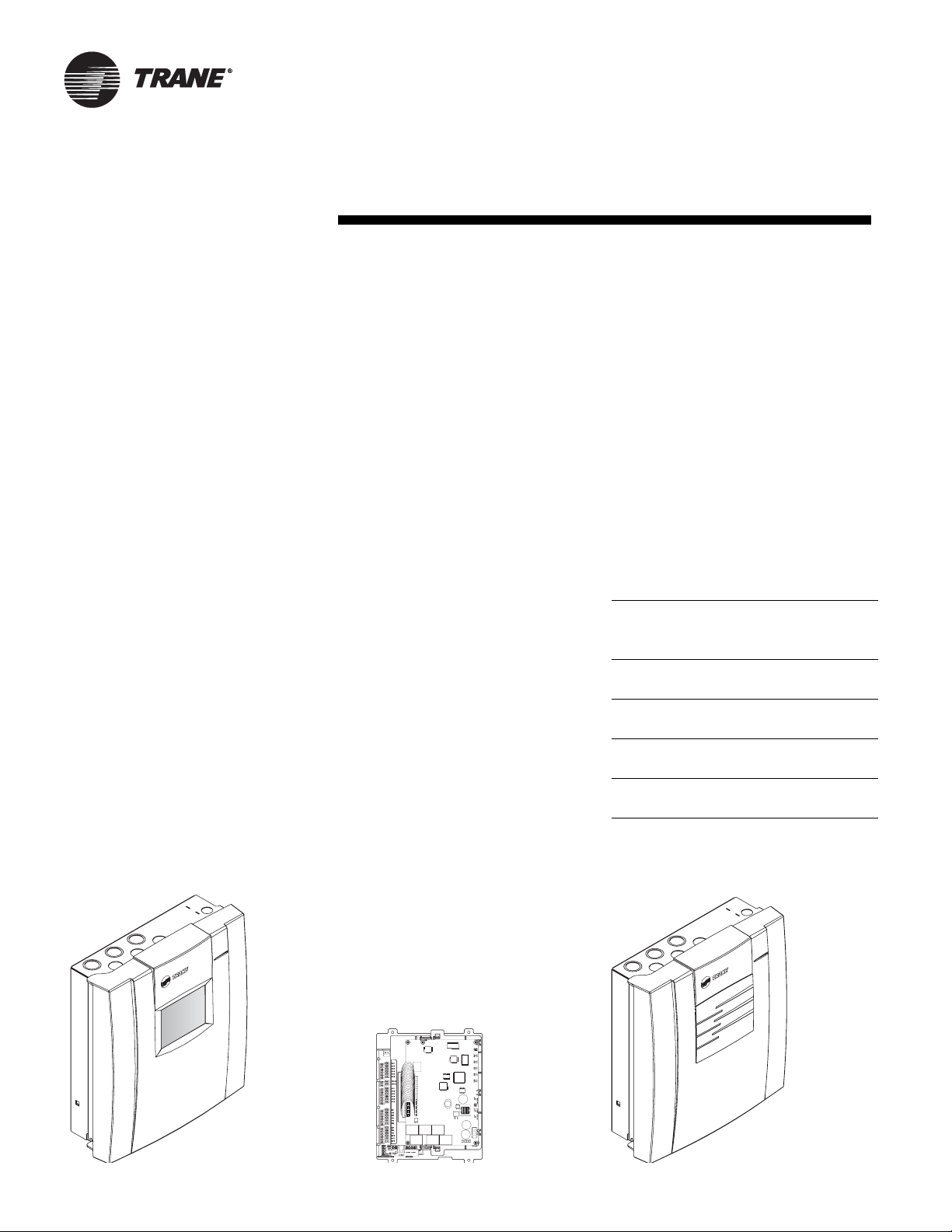
Several models of Tracer MP580/581
controllers are available. Tracer MP581
models are illustrated in Figure 1.
Tracer MP580 on Trane air handlers
The Tracer MP580 controller is available
packaged with the following air handlers:
• M-Series Climate Changer air handlers
• T-Series Climate Changer air handlers
• AireSystems custom air handlers
The controller is factory wired to all
sensors, actuators, valves, starters, and
other items shipped with the air handler.
Factory testing of connected points
helps minimize field commissioning
time and expense.
Frame-mounted Tracer MP581
The frame-mounted Tracer MP581
consists of a circuit board and a
termination board mounted in a twopiece modular-frame assembly. This
modular design allows the circuit board
to be stored separately while installation
and wiring are completed. The framemounted model can be installed in new
equipment or existing enclosures.
Tracer MP581 with NEMA-1 enclosure
The Tracer MP581 with enclosure
consists of the frame assembly
mounted in an enclosure compliant with
National Electrical Manufacturers
Association (NEMA) type-1 standards. A
line-to-low voltage transformer is
included. The enclosure has a hinged
door and plenty of room for input and
output wiring. The assembly is UL-listed.
Operator display models
Operator-display touch screens are
available as options for all Tracer MP580/
581 controllers. The operator-display
models are illustrated in Figure 2 on
page 5.
Door-mounted operator display
The door-mounted operator display
works with any Tracer MP581 or Tracer
AH541 controller. A retrofit kit is
available to add an operator display to an
existing Tracer MP581. The retrofit kit
includes a complete enclosure door with
an operator display mounted in it. The
door-mounted operator display is not
available for factory-mounted Tracer
MP580 controllers.
Stand-alone operator display
The stand-alone operator display is
designed for permanent local
connection to a Tracer MP580/581 or
AH540/541 controller. The stand-alone
operator display includes a 7-day time
clock to provide scheduling for the
associated controller. The 10-foot
(3 meter) connector cable can be
extended up to 150 feet (46 meters).
Portable operator display
The portable operator display is
designed for temporary connection to a
Tracer MP580/581 or AH540/541
controller. The operator-display touch
screen is mounted in a resin enclosure,
which is placed in a padded, protective
carrying case. A 10-foot (3 meter)
connector cable is included.
Expansion module
You can use up to four EX2 expansion
modules to add extra points to a Tracer
MP580/581 controller. The expansion
modules communicate with the
controller on an IEEE-485 I/O bus up to
1000 ft (300 m) from the controller. The
EX2 expansion module is available in
two models:
• EX2 module in a metal enclosure
• EX2 module with a plastic cover
The EX2 models are illustrated in
Figure 3 on page 5.
Table 1 lists the points available on
Tracer MP580/581 controllers and the
expansion modules. Refer to
“Specifications” on page 14 for details
about each type of point.
Table 1. Total points available
Typ e o f
point
Universal
inputs
Binary
outputs
Analog
outputs
Static pressure input
Tracer
MP580/
581
12 6 36
6422
6422
101
Each
EX2
(up to 4)
Total
points
Figure 1. Tracer MP581 models
Tracer MP581 with
optional operator display
Frame-mounted
Tracer MP581
4 CNT-PRC002-EN
Tracer MP581 without
operator display
Page 5
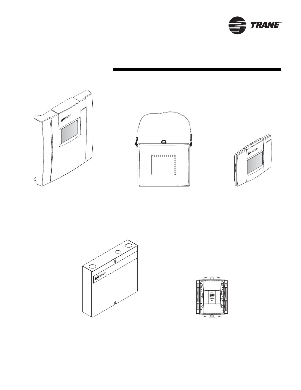
Figure 2. Operator display models
Door-mounted operator display
for Tracer MP581 controllers
Figure 3. EX2 expansion modules
EX2 in metal enclosure EX2 with plastic cover
Note: Expansion modules factory-installed with
Tracer MP580s consist of the circuit board only. The
modules shown here are available for field installation.
Portable operator display Stand-alone
operator display
CNT-PRC002-EN 5
Page 6

Features
Graphical programming
The Tracer graphical programming (TGP)
editor, shown in Figure 5 on page 7,
eliminates the need for line-by-line
programming. The TGP editor is a
software component of the Trane Rover
service tool. TGP has the following
advantages:
• Easy to learn—programming is as
easy as assembling logic blocks with a
computer mouse, much like creating a
flow chart.
• Powerful—the TGP editor has built-in
PID functions and more than 50 logic
blocks for building programs.
• Self documenting—programs can be
printed and used as pictorial representations of sequences of operation (see
Figure 6 on page 7).
• Programs are stored in the controller
along with their graphical representation, and can be uploaded, viewed,
and re-used.
• Offline programming—configuration
and TGP programming can be done
without connecting to a Tracer
MP580/581 controller.
• Program simulation—programmers
can simulate TGP programs offline.
The programmer can verify, test, and
troubleshoot controller operation at a
remote location, simplifying setup,
maintenance, and service.
Operator display
The optional operator-display touch
screen is an intuitive operator interface
for monitoring and changing building
control functions. With the operator
display, you can:
• Monitor space temperature, relative
humidity, and other variables
• Change setpoints and scheduled
occupancy times
• Identify and troubleshoot problems
• View and reset controller alarms
• Manually override outputs
The operator display includes a 7-day
time clock that gives Tracer MP580/581
controllers the ability to manage time-ofday scheduling, with two on/off times
per day and up to 20 exception
schedules per year.
Figure 2 on page 5 illustrates the
operator-display models available for
Tracer MP580/581 controllers.
Figure 4 shows a typical operator display
screen.
Figure 4. Typical status screen
Engineered smoke control
Tracer MP580/581 controllers and EX2
expansion modules can be used to
control an engineered smoke control
system. When used with a fire alarm
control panel (provided by other
suppliers), the smoke-control system
can help protect occupants by
controlling the flow of smoke during a
fire.
In addition to smoke control, with a
firefighter’s control panel, a firefighter
can see the status of smoke control and
implement overrides as required. The
Tracer MP580/581 and EX2 expansion
module are UL-864-UUKL-listed for this
application. For details, see the
Engineered Smoke Control System for
Tracer Summit applications guide, BASAPG 001-EN.
Interoperability
Tracer MP580/581 controllers
communicate by means of the LonTalk
protocol. The controllers can be
configured to conform to the LonMark
Space Comfort Controller (SCC) profile
or the Discharge Air Controller (DAC)
profile. You can integrate Tracer MP580/
581 controllers with any control system
that supports these LonTalk protocols
and FTT10-A communications.
®
Security
You can use up to eight security
passwords to limit access to a Tracer
MP580/581 controller.
Use the security passwords to prevent
unauthorized access to:
• TGP programs stored in the controller
• Operator display functions, such as
setpoints and schedules
• Configuration downloads from a
LonTalk service tool
For each of the security passwords, you
can choose what can and cannot be
accessed, including specific screens on
the operator display. The controller ships
with security disabled.
6 CNT-PRC002-EN
Page 7

Figure 5. TGP editor showing a supply fan program
Figure 6. TGP printout of a hot-water valve program
CNT-PRC002-EN 7
Page 8

Network architecture
Tracer MP580/581 controllers can
operate as stand-alone controllers, on a
peer-to-peer network, or as part of a
With an operator display, you can
monitor information and make control
changes on a peer-to-peer network.
Tracer Summit building automation
system (see Figure 7).
Figure 7. Tracer MP581 controller as part of a building automation system with Trane LonTalk controllers
Tr a c e r S u m m i t
PC Workstation
Building
control unit
(BCU)
Tracer AH541
Tracer ZN511 Tracer ZN521
Comm5 (LonTalk)
communications link
Tracer MP581
I/O bus for up to four expansion modules
EX2 module with
metal enclosure
Tracer MP501 Tracer MP503
Rover service tool
EX2 module
with plastic cover
8 CNT-PRC002-EN
Page 9

Wiring diagrams
Figure 8 shows typical input and output
connections to the Tracer MP581
termination board. The Tracer MP581
termination board uses screw terminals.
The Tracer MP580 termination board
uses 0.25-inch quick-connect terminals.
Figure 9 on page 10 shows typical input
and output connections to the EX2
expansion module.
Figure 8. Wiring diagram for the Tracer MP580/581
Powered output
<1000 ft
(300 m)
0–10 Vdc output
Load > 500 Ω
For wiring within a smoke control
system, see Applications Guide,
Engineered Smoke Control System for
Tracer Summit, BAS-APG001-EN.
<1000 ft
(300 m)
<300 ft
(100 m)
Temperature sensor
0–20 mA sensor
<1000 ft
(300 m)
I/O bus to EX2
expansion modules up
to 1000 ft (300 m)
CNT-PRC002-EN 9
Page 10

Figure 9. Wiring diagram for the EX2 expansion module
3-wire, 0–20 mA
sensor*
<1000 ft
(300 m)
24 Vac
transformer
2-wire, 0–20 mA
sensor
<1000 ft
(300 m)
Temperature sensor
<300 ft
(100 m)
I/O bus to Tracer MP580 and
EX2 expansion modules
up to 1000 ft (300 m)
*Note: Or a 3-wire 0–10 Vdc
sensor with a distance
limitation of 300 ft (100 m).
Powe red
output
<1000 ft
(300 m)
<300 ft
(100 m)
AC powered
actuator
10 CNT-PRC002-EN
Page 11

Enclosure interior
Figure 10. Tracer MP581 enclosure interior
Figure 10 shows the interior of the
Tracer MP581 NEMA-1 enclosure.
Significant space is available for wiring
inputs and outputs. Wires should be
routed after the optional pressure
sensor is installed.
Tracer MP580 enclosure configurations
are customized in the factory to meet
customer requirements.
For interior details of a Tracer MP581
used in a smoke control system, see
Applications Guide, Engineered Smoke
Control System for Tracer Summit, BAS-
APG 001-EN.
Line-to-low voltage
power transformer
Main circuit board
Space for input and
output wire-routing
Mounting location
for optional static
pressure sensor
Termination board
CNT-PRC002-EN 11
Page 12

Dimensions
Figure 11 shows the dimensions of the
Tracer MP581 NEMA-1 enclosure.
Figure 12 shows the dimensions of the
frame-mounted Tracer MP581 controller.
Figure 11. Tracer MP581 enclosure dimensions
The dimensions of the operator display
models are listed in “Specifications” on
page 14.
Figure 12. Frame-mounted Tracer MP581 dimensions
12 CNT-PRC002-EN
Page 13

Figure 13. EX2 plastic-cover module dimensions
5.625 in.
(143 mm)
5.375 in. (137 mm)
Figure 14. EX2 metal-enclosure module dimensions
9 in.
(25mm)
6.313 in.
(160 mm)
7 in.
(178 mm)
1.875 in.
(48 mm)
6.875 in.
(175 mm)
2 in. (51 mm)
6.5 in.
(165 mm)
0.28 in.
(7 mm)
9 in.
(229 mm)
10.37 in.
(263 mm)
with cover
2.25 in.
(58 mm)
CNT-PRC002-EN 13
1 in.
(25 mm)
10.25 in.
(260 mm)
without cover
Page 14

Specifications
Tracer MP580/581
The specifications in this section apply
to all Tracer MP580/581 models.
Inputs and outputs
Twelve universal inputs
Dry contact binary (including pulse
accumulation), 0–20 mA, 0–10 Vdc,
linear resistance, or thermistor. The
first four inputs can be used directly
with resistance temperature
detectors (RTDs).
Six binary outputs
Tracer MP580: 3 VA per ordered
binary output isolation relay
Tracer MP581: 12 VA at 24 Vac
powered relay contacts
Six analog outputs
0–10 Vdc or 0–20 mA
Static pressure input
Specialized input for a Trane
differential pressure sensor
(5 Vdc, 0–5 in. wc)
Analog-to-digital conversion
Resolution: 12 bits
Digital-to-digital conversion
Resolution: 12 bits
Microprocessor
Motorola MC68332 20 MHz
Memory
RAM: 512 K
ROM: 2 MB Flash
EEPROM: 256 K
Time clock
Included with operator display; crystal
controlled, super-capacitor backed
Battery
Not required—backed by super capacitor
for 7 days under normal operating
conditions; all other programs backed by
non-volatile memory
Agency listings/compliance
CE—Immunity (directive 89/336/EEC)
EN 50090-2-2:1996
CE—Emissions (directive 89/336/EEC)
EN 50090-2-2:1996
EN 61000-3-2:1995
EN 61000-3-3:1995
UL and C-UL listed
Energy management system
UL 916
FCC approved: Part 15, Class A
UL-864-UUKL
Engineered smoke control
Tracer MP581 with NEMA-1 enclosure
Power requirements
Nominal rating
120/230 Vac; 50/60 Hz; 1 phase
Voltage utilization range
120 Vac nominal: 98–132 Vac
230 Vac nominal: 196–264 Vac
Operating environment
From 32°F to 122°F (0°C to 50°C)
Humidity: 10–90% non-condensing
Storage environment
Temperature
Without display: From –58°F to 203°F
(–50°C to 95°C)
With display: From –13°F to 149°F
(–25°C to 65°C)
Humidity: 10–90% non-condensing
Dimensions
16.5 in. × 14.75 in. × 5.5 in.
(418 mm × 373 mm × 140 mm)
Minimum clearances
12 in. (30 cm) top, bottom, and right
24 in. (60 cm) left
36 in. (90 cm) front
Weight
15 lb (7 kg)
Mounting
Wall-mounted with #10 (5 mm) screws
Frame-mounted
Tracer MP581
Specifications not repeated here are the
same as for the NEMA-1 enclosure.
Power requirements
Nominal rating
24 Vac; 50/60 Hz; 1 phase
Voltage utilization range
24 Vac nominal: 19–30 Vac
Operating environment
From –40°F to 158°F (–40°C to 70°C)
Humidity: 10–90% non-condensing
Dimensions
10.25 in. × 8 in. × 3.5 in.
(260 mm × 203 mm × 89 mm)
Minimum clearances
0.5 in. (1.3 cm) top, right, and front
6 in. (15 cm) left (for I/O wiring)
3 in. (8 cm) bottom (for comm wiring)
Weight
2 lb (1 kg)
Mounting
Requires #8 (4 mm) screws
Factory-installed
Tracer MP580
Specifications not repeated here are the
same as for the NEMA-1 enclosure.
Enclosure
On M-Series air handlers, the Tracer
MP580 controller is mounted in a
galvanized steel enclosure to minimize
costs, facilitate factory mounting, and
match unit construction. On T-Series air
handlers, the Tracer MP580 controller is
mounted in a control panel inside the
unit.
Operator display
On M-Series air handlers, the operator
display can be mounted at the factory or
shipped loose for field installation.
Operator displays are shipped loose for
T-Series air handlers. Door-mounted
operator displays are not available for the
Tracer MP580.
14 CNT-PRC002-EN
Page 15

Operator display
Touch screen
Video graphics adapter (VGA) backlit
liquid crystal display (LCD) with touch
screen; 4.5 in. × 3.4 in. (115 mm ×
86 mm) viewable area; resolution of
320 × 240 pixels
Operating environment
From 32°F to 122°F (0°C to 50°C)
Humidity 10–90% non-condensing
Portable and stand-alone enclosure
dimensions
10.25 in. × 8.75 in. × 2.25 in.
(260 mm × 222 mm × 58 mm)
Mounting distance for stand-alone
operator display
10 ft (3 m) with attached cable;
extendable to 150 ft (46 m) as described
in the installation sheet for the standalone operator display (3270 3338).
EX2 expansion module
Inputs and outputs
Six universal inputs; four binary outputs;
four analog outputs
Mounting distance
Up to 1000 ft (300 m) from controller
Power requirements
Nominal rating
24 Vac; 50/60 Hz; 1 phase
Voltage utilization range
24 Vac nominal: 19–30 Vac
Operating environment
From –40°F to 158°F (–40°C to 70°C)
Humidity 5–95% non-condensing
Storage environment
From –40°F to 185°F (–40°C to 85°C)
Humidity 5–95% non-condensing
Dimensions
Metal-enclosure module:
10.25 in. × 9 in. × 2.25 in.
(260 mm × 229 mm × 58 mm)
Plastic-cover module:
6.875 in. × 5.375 in. × 2 in.
(175 mm × 137 mm × 51 mm)
Minimum clearances
Metal-enclosure module:
1 in. (25 mm) top, bottom
2 in. (51 mm) left, right
24 in. (610 mm) front
Plastic-cover module:
1 in. (25 mm) top, bottom
4 in. (102 mm) left, right, front
Weight
Metal-enclosure module: 8 lb (4 kg)
Plastic-cover module: 2 lb (1 kg)
CNT-PRC002-EN 15
Page 16

Trane
A business of American Standard Companies
www.trane.com
For more information, contact your local Trane
office or e-mail us at comfort@trane.com
Literature Order Number CNT-PRC002-EN
File Number PL-ES-CNT-PRC002-0806
Supersedes CNT-PRC002-EN March 2003
Stocking Location Inland
Trane has a policy of continuous product and product data improvement and reserves the right to
change design and specifications without notice.
 Loading...