

Page 1
Tracer™ Controllers
Tracer MP580/581
Programmable Controllers
September 2001
CNT-PRC002-EN
Page 2

© 2001 American Standard Inc.
™ ® The following are trademarks or registered trademarks of their respective
companies: LonTalk and LonMark from Echelon Corporation; Climate Changer, Rover,
T-Series, Tracer, and Tracer Summit from Trane.
Page 3

Contents
Product overview . . . . . . . . . . . . . . . . . . . 4
Applications . . . . . . . . . . . . . . . . . . . . . . . . . . . . . . . . 4
Product models . . . . . . . . . . . . . . . . . . . . . . . . . . . . . 4
Inputs and outputs . . . . . . . . . . . . . . . . . . . . . . . . . . 4
Features . . . . . . . . . . . . . . . . . . . . . . . . . . . 6
Graphical programming . . . . . . . . . . . . . . . . . . . . . . 6
Interoperability . . . . . . . . . . . . . . . . . . . . . . . . . . . . . 6
Operator display. . . . . . . . . . . . . . . . . . . . . . . . . . . . . 6
Dimensions . . . . . . . . . . . . . . . . . . . . . . . . 8
Network architecture . . . . . . . . . . . . . . . 10
Wiring diagram . . . . . . . . . . . . . . . . . . . . 11
Enclosure interior . . . . . . . . . . . . . . . . . . . 12
Specifications . . . . . . . . . . . . . . . . . . . . . 13
CNT-PRC002-EN 3
Page 4

Product overview
The Tracer MP580 programmable
controller is factory-installed on Trane
Modular and T-Series Climate Changer
air handlers.
The Tracer MP581 programmable
controller is available for field installation
for a variety of heating, ventilating, and
air-conditioning (HVAC) applications.
Applications
Tracer MP580/581 controllers support a
wide variety of building control
applications, including:
• Air-handler control
• Support of the LonMark Space Comfort Controller (SCC) profile and the
Discharge Air Controller (DAC) profile
for air handlers
• Control of mechanical-room equipment, including cooling towers,
pumps, boilers, and heat exchangers
• Supervisory control of an HVAC network for mid-sized buildings
• Nearly any control process needed in
a commercial building
Product models
Several models of Tracer MP580/581
controllers are available. Tracer MP581
models are illustrated in Figure 1 on
page 5. Operator-display touch screens
are available as an option for all models.
Tracer MP580 on Trane air handlers
The Tracer MP580 controller is available
packaged with Trane Modular and
T-Series Climate Changer air handlers.
The controller is factory wired to all
sensors, actuators, valves, starters, and
other items shipped with the air handler.
Factory testing of connected points
helps minimize field commissioning
time and expense.
Frame-mounted Tracer MP581
The frame-mounted Tracer MP581
consists of a circuit board and a
termination board mounted in a twopiece modular frame assembly. This
modular design allows the circuit board
to be programmed at a different location
while installation and wiring are
completed. The frame-mounted Tracer
MP581 can be mounted in new
equipment or an existing enclosure.
Tracer MP581 in a NEMA-1 enclosure
The Tracer MP581 with enclosure
consists of the frame assembly
mounted in an enclosure compliant with
National Electrical Manufacturers
Association (NEMA) type-1 standards. A
line-to-low voltage transformer provides
power to the electronics. The enclosure
has a hinged door and plenty of room for
input and output wiring. The complete
assembly is UL-listed.
Inputs and outputs
Tracer MP580/581 controllers have the
following inputs and outputs (illustrated
in Figure 8 on page 11):
• 12 universal inputs
Dry contact binary (including pulse
accumulation), 0–20 mA, 0–10 Vdc,
linear resistance, or thermistor. Four
of the twelve inputs can be used
directly with resistance temperature
detectors (RTDs).
• Static pressure input
Specialized input for a Trane
differential pressure sensor
(5 Vdc, 0–5 in. wc).
• 6 binary outputs
12 VA at 24 Vac powered relay
contacts.
• 6 analog outputs
0–10 Vdc or 0–20 mA.
4 CNT-PRC002-EN
Page 5
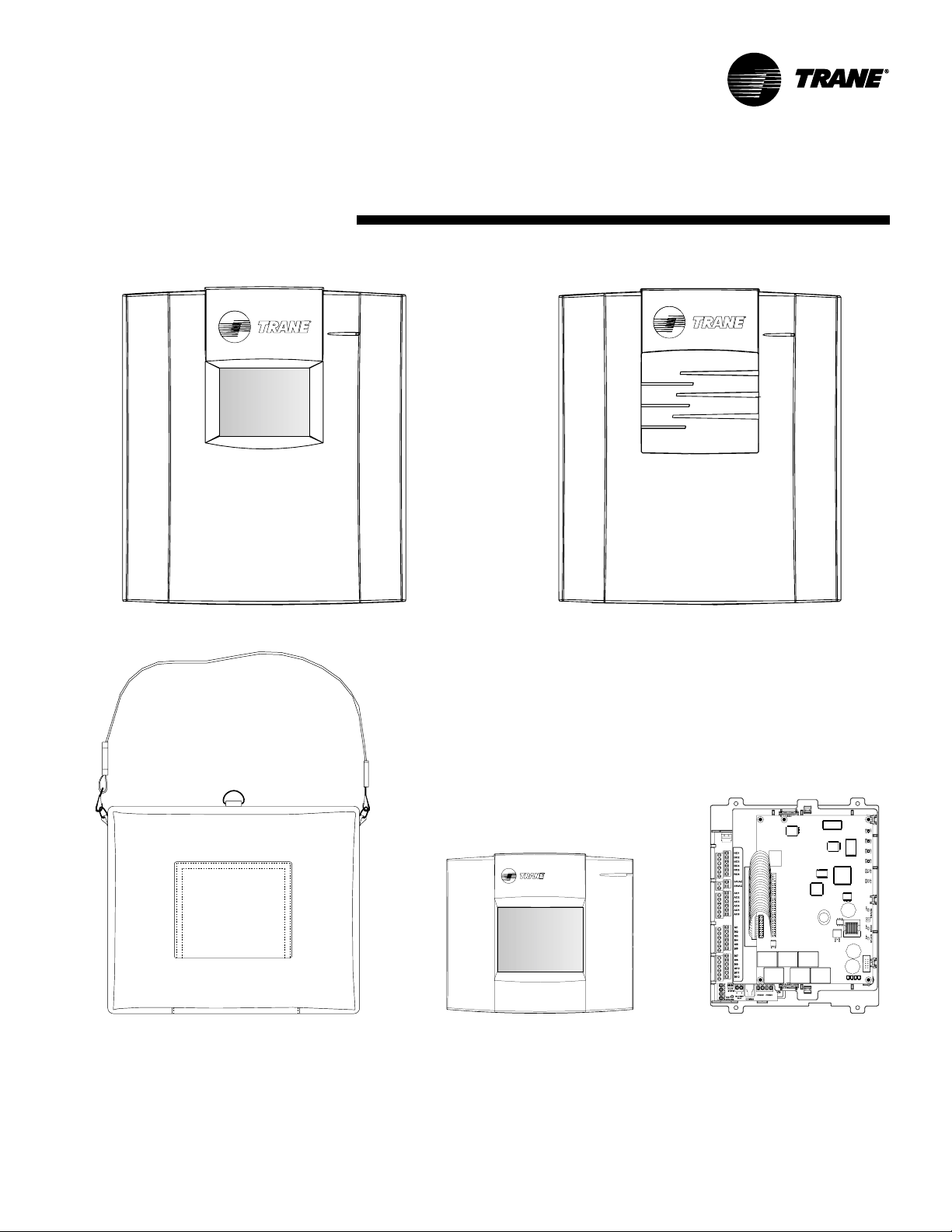
Figure 1: Tracer MP581 and operator display models
Tracer MP581 with optional operator display Tracer MP581 without operator display
Stand-alone operator displayPortable operator display
CNT-PRC002-EN 5
Frame-mounted Tracer MP581
Page 6

Features
Graphical programming
The Tracer graphical programming (TGP)
editor, shown in Figure 3 on page 7,
eliminates the need for line-by-line
programming. The TGP editor is a
software component of Trane’s Rover
service tool. TGP has the following
advantages:
• Easy to learn—programming is as
easy as assembling logic blocks with a
computer mouse, much like creating a
flow chart.
• Powerful—the TGP editor has built-in
PID functions and more than 50 logic
blocks for building programs.
• Self documenting—programs can be
printed and used as pictorial representations of sequences of operation (see
Figure 4 on page 7).
• Programs are stored in the controller
along with their graphical
representation, and can be uploaded,
viewed, and re-used.
Interoperability
Tracer MP580/581 controllers
communicate by means of the LonTalk
protocol. The controllers can be
configured to conform to the LonMark
Space Comfort Controller (SCC) profile
or the Discharge Air Controller (DAC)
profile. Tracer MP580/581 controllers
can work with any control system that
supports the LonTalk protocol and uses
FTT10-A communications.
Operator display
The optional operator-display touch
screen is an intuitive operator interface
for monitoring and changing building
control functions. With the operator
display you can:
• Monitor space temperature, relative
humidity, and other variables
• Change setpoints and scheduled
occupancy times
• Identify and troubleshoot problems
• View and reset controller alarms
• Manually override outputs
The operator display includes a 7-day
time clock that gives Tracer MP580/581
controllers the ability to manage time-ofday scheduling, with two on/off times
per day and up to 20 exception
schedules per year.
Figure 2 shows a typical operator display
screen.
Figure 2: Typical status screen
The operator display is available in the
following configurations:
• Door-mounted on the Tracer MP581
• Stand-alone operator display for
mounting up to 20 ft (7 m) away from
a Tracer MP580 or MP581
• Portable operator display for
temporary connections to the Tracer
MP580/581 or Tracer AH540/541
Figure 1 on page 5 illustrates the
operator displays available for the
Tracer MP581.
6 CNT-PRC002-EN
Page 7

Figure 3: TGP editor showing a supply fan program
Figure 4: TGP printout of a hot water valve program
CNT-PRC002-EN 7
Page 8

Dimensions
Figure 5 shows the dimensions of the
frame-mounted Tracer MP581 controller.
Figure 6 on page 9 shows the
dimensions of the Tracer MP581
NEMA-1 enclosure.
Figure 5: Frame-mounted Tracer MP581 dimensions
8 CNT-PRC002-EN
Page 9

Figure 6: Tracer MP581 enclosure dimensions
CNT-PRC002-EN 9
Page 10

Network architecture
Tracer MP580/581 controllers can
operate as stand-alone controllers, on a
peer-to-peer network, or as part of a
With an operator display, you can
monitor information and make control
changes on a peer-to-peer network.
Tracer Summit building automation
system (see Figure 7).
Figure 7: Tracer MP581 controller as part of a building automation system with Trane LonTalk controllers
Tracer Summit
PC Workstation
Building
control unit
(BCU)
Tracer MP581
Tracer ZN511 Tracer ZN521
Comm 5 (LonTalk)
communications link
Tracer MP501 Tracer MP503
Rover service tool
Tracer AH541
10 CNT-PRC002-EN
Page 11

Figure 8: Wiring diagram
Powered output
0–10 Vdc output
Load > 500
Wiring diagram
Figure 8 shows typical input and output
connections to the termination board.
For details on inputs and outputs, see
“Inputs and outputs” on page 4.
<1000 ft
(300 m)
Ω
Temperature sensor
0–20 mA sensor
<1000 ft
(300 m)
<300 ft
(100m)
<1000 ft
(300 m)
CNT-PRC002-EN 11
Page 12

Figure 9: Tracer MP581 enclosure interior
Enclosure interior
Figure 9 shows the interior of the Tracer
MP581 NEMA-1 enclosure.
Line-to-low voltage
power transformer
Main circuit board
Mounting location
for optional static
pressure sensor
Termination board
12 CNT-PRC002-EN
Page 13

Specifications
Power requirements
Nominal rating: 24/120/230 Vac;
50/60 Hz; 1 phase
Voltage utilization range
24 Vac (frame-mounted): 19–30 Vac
120 Vac nominal: 98–132 Vac
230 Vac nominal: 184–254 Vac
Operating environment
Temperature
Without display: From –40°F to 158°F
(–40°C to 70°C)
With display: From 32°F to 122°F
(0°C to 50°C)
Humidity: 10–90% non-condensing
Storage environment
Temperature
Without display: From –58°F to 203°F
(–50°C to 95°C)
With display: From –13°F to 149°F
(–25°C to 65°C)
Humidity: 10–90% non-condensing
Available enclosures
Tracer MP580: metal enclosure
packaged with air handler
Tracer MP581
NEMA-1 enclosure
Frame-mounted (no enclosure)
Dimensions
Tracer MP580 enclosure
15 in. × 8 ½ in. × 5 in.
(381 mm × 215 mm × 127 mm)
Tracer MP581 NEMA-1 enclosure
16 ½ in. × 14 ¾ in. × 5 ½ in.
(418 mm × 373 mm × 140 mm)
Frame-mounted Tracer MP581
10 ¼ in. × 8 in. × 3 ½ in.
(260 mm × 203 mm × 89 mm)
Minimum clearances
NEMA-1 enclosure
12 in. (30 cm) top, bottom, and right
24 in. (60 cm) left
36 in. (90 cm) front
Frame-mounted
½ in. (1.3 cm) top, right, and front
6 in. (15 cm) left (for I/O wiring)
3 in. (8 cm) bottom (for
communications wiring)
Weight
With NEMA-1 enclosure: 15 lb (7 kg)
Frame-mounted: 2 lb (1 kg)
Mounting
NEMA-1 enclosure: wall-mounted with
#10 (5 mm) screws
Frame-mounted: #8 (4 mm) screws
Analog-to-digital conversion
Resolution: 12 bits
Digital-to-digital conversion
Resolution: 12 bits
Microprocessor
Motorola MC68332 20 MHz
Memory
RAM: 512 K
ROM: 2 MB Flash
EEPROM: 256 K
Operator interface
Video graphics adapter (VGA) backlit
liquid crystal display (LCD) with touch
screen; 4.5 in. × 3.4 in. (115 mm ×
86 mm) viewable area; resolution of
320 × 240 pixels
Time clock
Included with operator display; crystal
controlled, super-capacitor backed
Battery
Not required—backed by super capacitor
for seven days under normal operating
conditions; all other programs backed by
non-volatile memory
Agency listings/compliance
CE—Immunity (directive 89/336/EEC)
EN 50090-2-2:1996
CE—Emissions (directive 89/336/EEC)
EN 50090-2-2:1996
EN 61000-3-2:1995
EN 61000-3-3:1995
UL and C-UL listed
Energy management system
UL 916
FCC approved: Part 15, Class A
CNT-PRC002-EN 13
Page 14

Page 15

Page 16

The Trane Company
An American Standard Company
www.trane.com
For more information contact
your local district office or
e-mail us at comfort@trane.com
Literature Order Number CNT-PRC002-EN
File Number PL-ES-CNT-000-PRC002-0901
Supersedes New
Stocking Location La Crosse
Since The Trane Company has a policy of continuous product and product data improvement, it
reserves the right to change design and specifications without notice.
 Loading...