

Trane City RTSF050, City RTSF060, City RTSF070, City RTSF090, City RTSF100 Installation Operation & Maintenance
...
Installation
Operation
Maintenance
Water-cooled Liquid Chillers
with Helical Rotary Compressors
RTSF: 180-385kW (R1234ze)
RLC-SVX023A

Contents
Introduction .......................................................................................................3
Unit model number description ....................................................................... 5
General Data ......................................................................................................7
Unit Description ................................................................................................. 8
Installation - Mechanical ................................................................................. 10
Installation - Electrical ..................................................................................... 21
Operating Principles Mechanical ....................................................................27
Typical Operating map ....................................................................................33
Controls/Tracer TD7 Operator Interface ......................................................... 34
Pre-Start Checkout ..........................................................................................35
Unit Start-up .................................................................................................... 37
Periodic Maintenance ...................................................................................... 38
Maintenance Procedures ................................................................................41
Recommended service routine frequencies .................................................. 46
Additional services .......................................................................................... 47
2 © Trane 2019
RLC-SVX023A

Introduction
Foreword
These instructions are given as a guide to good practice
in the installation, start-up, operation, and maintenance
by the user, of Trane City chiller RTSF, manufactured in
France. A separate manual is available for the use and
maintenance of the unit’s control, Tracer™ UC800. They
do not contain full service procedures necessary for the
continued successful operation of this equipment. The
services of a qualified technician should be employed
through the medium of a maintenance contract with a
reputable service company. Read this manual thoroughly
before unit start-up.
Units are assembled, pressure tested, dehydrated,
charged and tested in accordance with factory standard
before shipment.
Warnings and Cautions
Warnings and Cautions appear at appropriate sections
throughout this manual. Your personal safety and the
proper operation of this machine require that you follow
them carefully. The constructor assumes no liability
for installations or servicing performed by unqualified
personnel.
WARNING: Indicates a potentially hazardous situation
which, if not avoided, could result in death or serious
injury.
CAUTION: Indicates a potentially hazardous situation
which, if not avoided, may result in minor or moderate
injury. It may also be used to alert against unsafe
practices or for equipment or property-damage-only
accidents.
Safety Recommendations
To avoid death, injury, equipment or property damage,
the following recommendations should be observed
during maintenance and service visits:
1. The maximum allowable pressures for system leak
testing on low and high pressure side are given in
the chapter “Installation”. Insure to do not exceed test
pressure by using appropriate device.
2. Disconnect all power supplies before any servicing on
the unit.
3. Service work on the refrigeration system and the
electrical system should be carried out only by qualified
and experienced personnel.
4. To avoid any risk, it is recommended to place the unit
on an area with restricted access.
Reception
On arrival, inspect the unit before signing the delivery
note. Specify any visible damage on the delivery note,
and send a registered letter of protest to the last carrier
of the goods within 7 days of delivery.
Notify the local TRANE sales office at the same
time. The delivery note must be clearly signed and
countersigned by the driver.
Any concealed damage shall be notified by a registered
letter of protest to the last carrier of the goods within
7 days of delivery. Notify the local TRANE sales office
at the same time.
Important notice: No shipping claims will be accepted
by TRANE if the above mentioned procedure is not
respected.
For more information, refer to the general sales
conditions of your local TRANE sales office.
Note: Unit inspection in France. Delay to send registered
letter in case of visible and concealed damage is only
72 hours.
Loose Parts Inventory
Check all the accessories and loose parts that are
shipped with the unit against the shipping list. Included
in these items will be the Water Flow Switch (optional),
rigging and electrical diagrams, service literature, which
are placed inside the control panel and/or starter panel
for shipment.
If optional elastomeric isolators are ordered with
the unit they are shipped mounted on the horizontal
support frame of the chiller. The isolators’ location and
distribution weight diagram is placed with the service
literature inside the starter/control panel.
Warranty
Warranty is based on the general terms and conditions
of the manufacturer. The warranty is void if the
equipment is repaired or modified without the written
approval of the manufacturer, if the operating limits are
exceeded or if the control system or the electrical wiring
is modified. Damage due to misuse, lack of maintenance
or failure to comply with the manufacturer’s instructions
or recommendations is not covered by the warranty
obligation. If the user does not conform to the rules of
this manual, it may entail cancellation of warranty and
liabilities by the manufacturer.
RLC-SVX023A
3

Introduction
Unit Description
The RTSF units are helical-rotary type, water-cooled,
liquid chillers, designed for installation indoors.
The RTSF units are packaged with an evaporator
and condenser.
Note: Each RTSF unit is a completely assembled,
hermetic package that is factory-piped, wired, leak
tested, dehydrated, charged and tested for proper control
operations prior to shipment. The chilled water inlet and
outlet openings are covered for shipment.
The RTSF series features Trane’s exclusive Adaptive
Control logic with UC800 controls. It monitors the control
variables that govern the operation of the chiller unit.
Adaptive Control logic can correct these variables, when
necessary, to optimize operational efficiencies, avoid
chiller shutdown, and keep producing chilled water.
Compressor loading/unloading is provided by AFD
(Adaptive Frequency Drive) coordinated with slide
valve operation.
Each refrigerant circuit is provided with filter, sight glass,
electronic expansion valve, and charging valves on
the RTSF.
The evaporator and condenser are manufactured
in accordance with Pressure Equipment Directive
standards. The evaporator and the condenser are
insulated according the option ordered. Both evaporator
and condenser water pipes are equipped with water
drain and vent connections.
Maintenance contract
It is strongly recommended that you sign a maintenance
contract with your local Trane Service Agency. This
contract provides regular maintenance of your
installation by a specialist in our equipment. Regular
maintenance ensures that any malfunction is detected
and corrected in good time and minimizes the possibility
that serious damage will occur. Finally, regular
maintenance ensures the maximum operating life of
your equipment. We would remind you that failure to
respect these installation and maintenance instructions
may result in immediate cancellation of the warranty.
Training
To assist you in obtaining the best use of it and
maintaining it in perfect operating condition over a long
period of time, the manufacturer has at your disposal
a refrigeration and air conditioning service school. The
principal aim of this is to give operators and technicians
a better knowledge of the equipment they are using,
or that is under their charge. Emphasis is particularly
given to the importance of periodic checks on the
unit operating parameters as well as on preventive
maintenance, which reduces the cost of owning the unit
by avoiding serious and costly breakdown.
Refrigerant
Consult the addendum to Manuals for units with
refrigerant, for conformity to the Pressure Equipment
Directive (PED) 97/23/EC or 2014/68/EU and Machinery
Directive 2006/42/EC and for specific caution for R1234ze.
4
RLC-SVX023A

Unit model number description
Digit 1, 2, 3, 4 – Unit Model
RTSF
Digit 5, 6, 7 – Unit size
50 = 50 Nominal tons
60 = 60 Nominal tons
70 = 70 Nominal tons
90 = 90 Nominal tons
100 = 100 Nominal tons
110 = 110 Nominal tons
Digit 8 – Unit Power supply
D = 400 V – 50 Hz – 3Ph
Digit 9 – Factory
E = Europe
F = ICS
Digit 10 & 11 – Design sequence
(Factory assigned)
Digit 12 & 13 – Not used
Digit 14 – Agency listing
C = CE marking
Digit 15 – Pressure Vessel Code
2 = PED (Pressure Equipment Directive)
Digit 16 – Unit Application
X = Cooling Mode - Below 50°C Leaving Condenser Temp
H = Cooling Mode - Above 50°C Leaving Condenser Temp
L = Heat pump - Below 50°C Leaving Condenser Temp
M = Heat pump - Above 50°C Leaving Condenser Temp
Digit 27 – Not Used
Digit 28 – Evaporator pump
X = Without
Digit 29 – Condenser Size
A = Condenser A
B = Condenser B
C = Condenser C
D = Condenser D
Digit 30 & 31 – Not Used
Digit 32 – Condenser Pump
X = Without
Digit 33 – Condenser Water side pressure
X = 10 Bar Condenser Water Pressure
Digit 34 – Condenser Thermal Insulation
X = Without
H = With Condenser Insulation
Digit 35 – Oil cooler
X = Without
C = With
Digit 36 – Evaporator Pump Smart Flow control
X = Without
E = VPF Constant Delta T Evaporator
Digit 37 – Power Protection
F = Disconnect switch with fuses
B = Disconnect switch with circuit breakers
Digit 17 – Refrigerant
Z = R1234ze unit with Factory charge (with oil)
Y = R1234ze with pre-charge (with oil)
L = R1234ze unit with Nitrogen (no oil)
Digit 18 – Sound Attenuation Package
X = Without
A = Aesthetic option
L = Sound attenuation package
Digit 19 – Relief Valve Option
L = Single Relief Valve Condenser
2 = Single Relief Valve Condenser & Evaporator
D = Dual relief valve with 3 way valve condenser
4 = Dual relief valve with 3 way valve condenser & Evaporator
Digit 20 – Compressor Type
L = CHHP Low VI
H = CHHP or CHHW High VI
Digit 21 – Evaporator Size
A = Evaporator A
B = Evaporator B
C = Evaporator C
D = Evaporator D
Digit 22 & 23 & 24 – Not Used
Digit 25 – Evaporator Water side Pressure
X = 10 Bar Evaporator Water Pressure
Digit 26 – Evaporator application
N = Comfort Cooling (above 5°C)
P = Process Cooling below 5°C
C = Ice Making (from -7°C to 20°C)
Digit 38 – Not Used
Digit 39 – Relay Card
1 = With additional relay card
Digit 40 – Smart com protocol
X = Without
B = BACnet MSTP interface
C = BACnet IP interface
M = Modbus RTU interface
L = LonTalk interface
Digit 41 – Communication customer input/output
X = Without
A = External Set points & Capacity outputs – Voltage Signal
B = External Set points & Capacity outputs – Current Signal
Digit 42 – Outdoor Air Temperature Sensor
X = Without
A = Outdoor Air Temperature Sensor – CWR/Low Ambient
Digit 43 – Not Used
Digit 44 – Master Slave Set
X = Without
M = With
RLC-SVX023A
5

Unit model number description
Digit 45 – Energy meter
X = Without
M = With
Digit 46 – Condenser Pump Smart Flow Control/Other Condenser
Pressure Control Outputs
X = Without
1 = Condenser Pressure in % HPC
2 = Differential Pressure
3 = Condenser Head Pressure Flow Control
4 = VPF Constant Delta T Condenser Flow Control
Digit 47 – Power socket
X = Without
P = Included (230V-100W)
Digit 48 – Factory test
X = Without
B = Visual Inspection
E = Test E - 1 point with Report Non Witnessed
S = Special test
Digit 49 – Installation Accessory
X = Without
1 = Neoprene isolators
4 = Neoprene pads
Digit 50 – Connection Accessory
X = Grooved pipe connection
W = Grooved pipe with coupling and pipe stub
Digit 51 – Flow switch
X = Without
A = Evaporator or Condenser
B = Evaporator and Condenser
Digit 52 – Literature Language
C = Spanish
D = German
E = English
F = French
H = Dutch
I = Italian
M = Swedish
P = Polish
R = Russian
T = Czech
V = Portugese
6 = Hungarian
8 = Turkish
Digit 53 – Not Used
Digit 54 – EXV selection
X = Standard EXV
Digit 55 – AFD Selection
A = AFD A
B = AFD B
C = AFD C
D = AFD D
E = AFD E
F = AFD F
Digit 56 – Design special
X = Without
S = Special
6
RLC-SVX023A

General Data
Table 1 – General Data RTSF Standard efficiency - R1234ze
Indicative performances (1)
Cooling Capacity (1) (kW) 183 220 264 314 363 388
Total Power input in cooling (1) (kW) 37 43 53 64 80 90
Unit Electrical data (2) (5)
Low VI compressor - digit 20 =L
Maximum Power Input (kW) 66 77 91 111 130 Unit rated amps (2) (A) 100 117 138 168 196 Unit start up amps (2) (A) 100 117 138 168 196 Displacement power factor 0.95 0.95 0.95 0.95 0.95 -
High VI compressor - Digit 20 = H
Maximum Power Input (kW) 87 103 125 150 178 178
Unit rated amps (2) (A) 131 155 190 227 270 270
Unit start up amps (2) (A) 131 155 190 227 270 270
Displacement power factor 0.95 0.95 0.95 0.95 0.95 0.95
Short Circuit Unit Capacity (kA) 35 35 35 35 35 35
Max Power cable (cross) mm² 1x 240 1x 240 1x 240 1x 240 1x 240 1x 240
Disconnect switch size (3) (A) 400 400 400 400 400 400
Compressor
Type Screw Screw Screw Screw Screw Screw
Model 60 70 85 100 120 140
Low VI compressor - digit 20 =L
Max compressors Power Input (kW) 65 76 91 110 129 Max Amps (3) (6) (A) 98 115 136 166 194 Start up Amps (A) 98 115 136 166 194 -
High VI compressor - Digit 20 = H
Max compressors Power Input (kW) 86 102 124 149 177 177
Max Amps (3) (6) (A) 129 153 188 225 268 268
Start up Amps (A) 129 153 188 225 268 268
Motor RPM (rpm)
Oil sump heater (kW) 0.275 0.275 0.275 0.275 0.275 0.275
Evaporator
Type BPHE BPHE BPHE BPHE BPHE BPHE
Evaporator model C B B A A A
Evaporator Water Content volume (l) 52 59 69 92 92 92
Evap. Water Flow rate - Minimum (4) (l/s) 3.6 4.8 4.8 6.4 6.4 6.4
Evap. Water Flow rate - Maximum (4) (l/s) 38.6 38.6 38.6 38.6 38.6 38.6
Nominal water connection size (Grooved coupling) (in) - (mm) 4" 4" 4" 4" 4" 4"
Condenser
Type BPHE BPHE BPHE BPHE BPHE BPHE
Condenser model B B A A A A
Condenser Water Content volume (l) 49 49 69 69 69 69
Cond. Water Flow rate - Minimum (4) 1.9 1.9 2.7 2.7 2.7 2.7
Cond. Water Flow rate - Maximum (4) 39 39 39 39 39 39
Nominal water connection size (Grooved coupling) (l) 4” 4” 4” 4” 4” 4”
Dimensions
Unit Length (mm) 2334 2334 2334 2334 2334 2334
Unit Width (mm) 922 922 922 922 922 922
Unit Height (mm) 1941 1941 1959 1959 1959 1959
Weights
Shipping Weight (5) (kg) 1611 1675 1900 1986 1986 1986
Operating Weight (5) (kg) 1690 1771 2018 2127 2127 2127
System data (6)
Nb of refrigerant circuits # 1 1 1 1 1 1
Minimum cooling load % % 25% 25% 25% 25% 25% 25%
Standard unit
R1234ze refrigerant charge (6) (kg) 31 34 42 47 47 47
Oil charge (6) (l) 5 5 7 7 7 7
POE Oil type OIL0066E/OIL0067E
RTSF050 RTSF060 RTSF070 RTSF090 RTSF100 RTSF110
(1) Indicative performance at Evaporator water temperature: 12°C / 7°C - Condenser water temperature 30 / 35°C - for detailed performances consult
order write up.
(2) Under 400V/3/50Hz.
(3) Option fuse + disconnect switch.
(4) Height reaches 2050 mm with the sound attenuation package option.
(5) Additional weight of + 158kg in case of a sound attenuation package option.
(6) Electrical & system data are indicative and subject to change without notice. Please refer to unit nameplate data.
RLC-SVX023A
7

Unit Description
Component location for typical RTSF Unit
16
13
2
5
17
18
15
14
2 = Power cable gland plate
for customer wiring
4 = Suction line
5 = Oil separator
6 = Condenser water outlet
7 = Condenser water inlet
4
5
9
8 = Evaporator water outlet
9 = Evaporator water inlet
13 = External control wiring
cable gland plate for
customer wiring
14 = Compressor
15 = Discharge line
16 = Unit nameplate (on the
side of starter/control
panel)
17 = EXV
18 = Condenser
1 = Control panel
3 = Tracer TD7 interface
4 = Suction line
10 = Auxiliary Oil Cooler (Optional)
11 = Evaporator
12 = Adaptive Frequency Drive
8
6
4
10
11 12
7
3
1
8
RLC-SVX023A

Unit Description
Installation overview and
requirements
Contractor responsibilities
A list of the contractor responsibilites typically associated
with the installation process is provided in Table 2.
• Locate and maintain the loose parts. Loose parts are
located in the control panel.
• Install the unit on a foundation with flat support surfaces,
level within 5 mm and of sufficient strength to support
concentrated loading. Place the manufacturer-supplied
isolation pad assemblies under the unit.
• Install the unit per the instructions outlined in the
“Mechanical Installation” section.
• Complete all water piping and electrical connections.
Note: Field piping must be arranged and supported to
avoid stress on the equipment. It is strongly recommended
that the piping contractor provide at least 1m of clearance
between the pre-installation piping and the planned location
of the unit. This will allow for proper fit-up upon arrival
of the unit at the installation site. All necessary piping
adjustments can be made at that time
• Where specified, supply and install valves in the water
piping upstream and downstream of the evaporator and
condenser, to isolate the heat exchangers for maintenance
and to balance/trim the system.
• Supply and install flow switches or equivalent devices
in both the chilled water and condenser water piping.
Interlock each switch with the proper pump starter and
Tracer UC800, to ensure that the unit can only operate
when water flow is established.
• Supply and install taps for thermometers and pressure
gauges in the water piping, adjacent to the inlet and outlet
connections of both the evaporator and the condenser.
• Where specified, supply and install strainers ahead of all
pumps and automatic modulating valves.
• Supply and install refrigerant pressure relief piping from
the pressure relief to the atmosphere.
• Start the unit under supervision of a qualified service
technician.
• Where specified, supply and insulate the evaporator
and any other portion of the unit, as required, to prevent
sweating under normal operating conditions.
• For unit-mounted starters, cutouts are provided at the top
of the panel for line-side wiring.
• Supply and install the wire terminal lugs to the starter.
• Supply and install field wiring to the line-side lugs of the
starter.
Table 2 – Installation Responsibility
Requirement
Foundation Meet foundation requirements
Rigging Safety chains
Isolation Isolation pads Other type of isolators
Electrical - Circuit breakers or fusible
Water piping Flow switches (may be eld
Insulation Insulation Insulation
Water piping connection
components
Caution on exposure to
refrigerant
Trane supplied
Trane installed
disconnects (Optional)
- Unit mounted starter
- Wye Delta starter or AFD
(Adaptive Frequency Drive)
- Grooved pipe
- Grooved pipe to agged
connection (optional)
Trane supplied
Field installed
- Flow switches (may be eld
supplied)
- Harmonic lters (on request
according to customer electrical
network and equipment)
supplied)
Customer supplied
Customer installed
Clevis connectors
Lifting beams
- Circuit breakers or fusible disconnect
- Electrical connections to unit mounted
starter (optional)
- Electrical connections to remote
mounted starter (optional)
- Wiring sizes per submittal and local
regulations
- Terminal lugs
- Ground connections
- BAS wiring (optional)
- Control voltage wiring
- Chilled water pump contactor and
wiring including interlock
- Option relays and wiring
- Taps for thermometers and gauges
- Thermometers
- Strainers (as required)
- Water ow pressure gauges
- Isolation and balancing valves in water
piping
- Vents and drain on waterbox valves
- Pressure relief valves for water side
Respect recommendation of IOM
addendum
RLC-SVX023A
9

Installation - Mechanical
Storage
If the chiller is to be stored more than one month prior to
installation, observe the following precautions:
• Do not remove the protective coverings from the
electrical panel.
• Store the chiller in a dry, vibration-free, secure area.
• At least every three months, attach a gauge and
manually check the pressure in the refrigerant circuit.
If the refrigerant pressure is below 3.4 bar at 21°C (2 bar
at 10 °C), call a qualified service organization and the
appropriate Trane sales office.
NOTE: Pressure will be approximately 1.0 bar if shipped
with the optional nitrogen charge.
Noise Considerations
• Refer to Engineering Bulletin for sound consideration
applications.
• Locate the unit away from sound-sensitive areas.
• Install the isolation pads under the unit. Refer to “Unit
Isolation.”
• Install rubber vibration isolators in all water piping.
• Use flexible electrical conduit for final connection to the
Tracer UC800.
• Seal all wall penetrations.
NOTE: Consult an acoustical engineer for critical
applications.
Foundation
Provide rigid, non-warping mounting pads or a concrete
foundation of sufficient strength and mass to support the
chiller operating weight (including completed piping and
full operating charges of refrigerant, oil and water).
Refer to General information for unit operating weights.
Once in place, level the chiller within 5 mm over its
length and width.
The manufacturer is not responsible for equipment
problems resulting from an improperly designed or
constructed foundation.
Clearances
Provide enough space around the unit to allow the
installation and maintenance personnel unrestricted
access to all service points. A minimum of 1 m is
recommended for compressor service and to provide
sufficient clearance for the opening of control panel
doors. In all cases, local codes will take precedence
over these recommendations. If the room configuration
requires a variance to the clearance dimensions, contact
your sales representative.
NOTE: Required vertical clearance above the unit is at
least 1 m. There should be no piping or conduit located
over the compressor motor.
NOTE: Maximum clearances are given. Depending on
the unit configuration, some units may require less
clearance than others in the same category.
Ventilation
The unit produces heat even though the compressor is
cooled by the refrigerant. Make provisions to remove
heat generated by unit operation from the equipment
room. Ventilation must be adequate to maintain an
ambient temperature lower than 40°C. Vent the pressure
relief valves in accordance with all local and national
codes. Refer to “Pressure Relief Valves”. Make provisions
in the equipment room to keep the chiller from being
exposed to ambient temperatures below 10°C.
Water Drainage
Locate the unit near a large capacity drain for water
vessel drain-down during shutdown or repair. Condenser
and evaporator water pipes are provided with drain
connections. Refer to “Water Piping.” All local and
national codes apply.
Access Restrictions
Refer to the unit submittals for specific dimensional
information (documents supplied in document package
coming with unit).
Vibration Eliminators
• Provide rubber boot type isolators for all water piping
at the unit.
• Provide flexible conduit for electrical connections to the
unit.
• Isolate all pipe hangers and be sure they are not
supported by main structure beams that could
introduce vibration into occupied spaces.
• Make sure that the piping does not put additional stress
on the unit.
NOTE: Do not use metal braided type eliminators on the
water piping. Metal braided eliminators are not effective
at the frequencies at which the unit will operate.
10
RLC-SVX023A
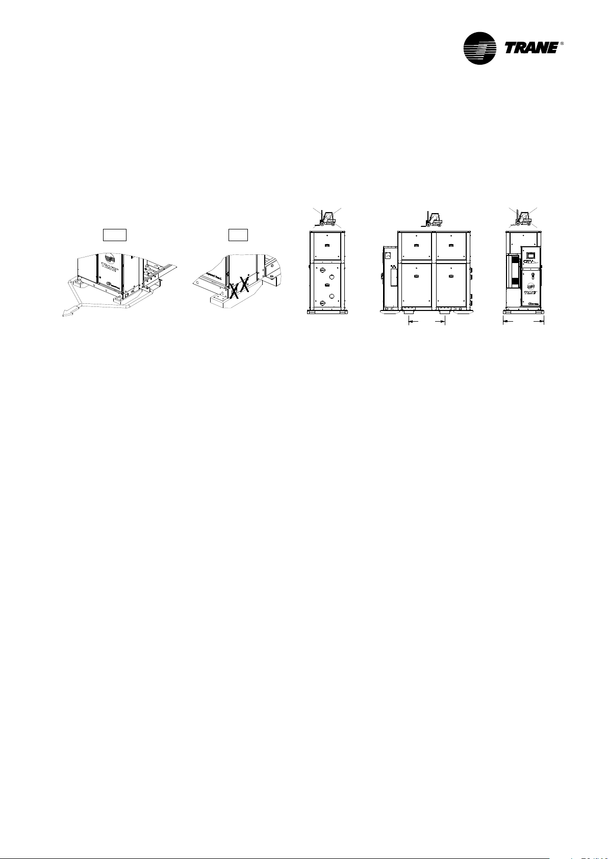
Handling Procedure
INSTRUCTIONS DE LEVAGE ET DE MANUTENTION
IL EST RECOMMANDE D'UTILISER LES ORGANES DE LEVAGE ET DE MANUTENTION
MONTRES PAR LE SCHEMA ET DE SUIVRE LES INSTRUCTIONS SUIVANTES :
1 -ATTENTION : CETTE UNITE DOIT ETRE LEVEE ET MANUTENTIONNEE AVEC
PRECAUTIONS. EVITER LES A-COUPS LORS DU LEVAGE ET DE LA MANUTENTION.
ANWEISUNGEN FUER DEN TRANSPORT MIT HEBEZEUG
ES WIRD EMPFOHLEN, DIE MASCHINE ENTSPRECHEND DER ZEICHNUNG MIT EINEM
KRAN ANZUHEBEN UND DIE FOLGENDEN ANWEISUNGEN ZU BEACHTEN :
1 -BEIM ANHEBEN VORSICHTIG VORGEHEN, STOESSE UND ERSCHUETTERUNGEN
UNBEDINGT VERMEIDEN.
SPECIAL LIFTING AND MOVING INSTRUCTIONS
IT IS RECOMMENDED TO USE THE SPECIAL BUILT-IN RIGGING POINTS SHOWN
IN THE DIAGRAM AND TO FOLLOW THE FOLLOWING INSTRUCTIONS :
1 -CAUTION : THIS UNIT MUST BE LIFTED AND HANDLED WITH CARE. AVOID SHOCKS
WHILE HANDLING.
ISTRUZIONI PER IL SOLLEVAMENTO E LA MOVIMENTAZIONE DELL'UNITA
SI RACCOMANDA DI SEGUIRE LE ISTRUZIONI QUI RIPORTATE PER IL SOLLEVAMENTO
E LA MOVIMENTAZIONE DELL'UNITA :
1 -ATTENZIONE : EFFETTUARE IL SOLLEVAMENTO DELL'UNITA CON LA MASSIMA CURA
EVITARE CARICHI ECCESSIVI, SOLLEVARE LENTAMENTE E UNIFORMEMENTE.
HIJS EN TRANSPORT INSTRUCTIES
DE TOE TE PASSEN HIJSMETHODE IS ALS VOLGT VOORGESCHREVEN :
1 -WAARSCHUWING : DEZE MACHINE VOORZICHTIG VERPLAATSEN. VOORKOM
SCHOKKEN EN STOTEN BIJ HET HIJSEN.
INSTRUCCIONES DE TRANSPORTE Y DESCARGA
SE RECOMIENDA SEGUIR LAS INSTRUCCIONES SIGUIENTES PARA LA CARGA Y
DESCARGA DE LA UNIDAD :
1 -ATENCION : ESTA UNIDAD DEBE SER DESCARGADA CON EL MAYOR CUIDADO
PARA EVITAR CHOQUES. DESCARGAR DESPACIO Y CUIDADOSAMENTE.
B
RTSF
050-060-070-090-100-110
57384397
Sheet 1 of 2
Date: Revision: B
19-DEC-2018
INSTRUCTIONS DE LEVAGE ET DE MANUTENTION
IL EST RECOMMANDE D'UTILISER LES ORGANES DE LEVAGE ET DE MANUTENTION
MONTRES PAR LE SCHEMA ET DE SUIVRE LES INSTRUCTIONS SUIVANTES :
1 -ATTENTION : CETTE UNITE DOIT ETRE LEVEE ET MANUTENTIONNEE AVEC
PRECAUTIONS. EVITER LES A-COUPS LORS DU LEVAGE ET DE LA MANUTENTION.
ANWEISUNGEN FUER DEN TRANSPORT MIT HEBEZEUG
ES WIRD EMPFOHLEN, DIE MASCHINE ENTSPRECHEND DER ZEICHNUNG MIT EINEM
KRAN ANZUHEBEN UND DIE FOLGENDEN ANWEISUNGEN ZU BEACHTEN :
1 -BEIM ANHEBEN VORSICHTIG VORGEHEN, STOESSE UND ERSCHUETTERUNGEN
UNBEDINGT VERMEIDEN.
SPECIAL LIFTING AND MOVING INSTRUCTIONS
IT IS RECOMMENDED TO USE THE SPECIAL BUILT-IN RIGGING POINTS SHOWN
IN THE DIAGRAM AND TO FOLLOW THE FOLLOWING INSTRUCTIONS :
1 -CAUTION : THIS UNIT MUST BE LIFTED AND HANDLED WITH CARE. AVOID SHOCKS
WHILE HANDLING.
ISTRUZIONI PER IL SOLLEVAMENTO E LA MOVIMENTAZIONE DELL'UNITA
SI RACCOMANDA DI SEGUIRE LE ISTRUZIONI QUI RIPORTATE PER IL SOLLEVAMENTO
E LA MOVIMENTAZIONE DELL'UNITA :
RELEASED 21/Dec/2018 09:34:29 GMT
Follow instructions given in the lifting and handling
document supplied with documentation package
shipped with the unit.
Figure 1 – Handling
YES NO
Installation - Mechanical
Isolation Pads
1. The elastomeric pads shipped (as standard) are
adequate for most installations. For additional details
on isolation practices, consult an acoustical engineer
for sensitive installations. It is possible that some
vibration frequencies can be transmitted into the
foundations. This depends on the building structure.
It is recommended for these situations to use neoprene
isolators instead of elastomeric pads.
Drawings to locate isolation pads are supplied with
unit document package.
2. During final positioning of the unit, place the isolation
pads as indicated in submittal drawings. Level
the unit.
Drawings to locate isolation pads are included with in
document package sent with the unit.
RLC-SVX023A
930
1042
11

Installation - Mechanical
Unit Leveling
NOTE: The electrical panel side of the unit is designated
as the “front” of the unit.
1. Check unit level end-to-end by placing a level on the
chiller structure (compressor frame for example).
2. Adjust to within 5 mm of level front-to-back.
Water Piping
Piping Connections
To prevent equipment damage, bypass the unit if using
an acidic flushing agent.
Make water piping connections to the evaporator
and condenser. Isolate and support piping to prevent
stress on the unit. Construct piping according to local
and national codes. Insulate and flush piping before
connecting to unit.
The chilled water connections to the evaporator are to be
grooved-pipe type connections. Do not attempt to weld
these connections. Refer to submittal for dimension of
tube stub for grooved connection. Refer to submittal for
dimension of tube stub for grooved connection.
To prevent damage to chilled water components, do not
allow evaporator pressure (maximum working pressure)
to exceed 10 bar.
Reversing Water Connections is prohibited
It is critical to keep the factory layout for water
connections. Therefore reversing water connections may
lead to functional disorder.
NOTE: Dimensions of tube stub for grooved connection
are included in submittal drawings.
Vents and Drains
Install pipe plugs in evaporator and condenser water
connections drain and vent connections before filling
the water systems. To drain water, remove vent and drain
plugs, install a NPT connector in the drain connection
and connect a hose to it.
Water Treatment
WARNING: Do not use untreated or improperly treated
water. Use of untreated or improperly treated water may
result in equipment damage.
The following disclamatory label is provided on
each unit:
The use of improperly treated or untreated water in this
equipment may result in scaling, erosion, corrosion,
algae or slime. The services of a qualified water
treatment specialist should be engaged to determine
what treatment, if any, is advisable. The warranty
specifically excludes liability for corrosion, erosion
or deterioration of the manufacturer’s equipment.
The manufacturer assumes no responsibilities for the
results of the use of untreated or improperly treated
water, or saline or brackish water.
12
RLC-SVX023A

Installation - Mechanical
Evaporator Piping Components
Note: Make sure all piping components are between the
shutoff valves, so that isolation can be accomplished
on both the condenser and the evaporator. “Piping
components” include all devices and controls used
to provide proper water system operation and unit
operating safety. These components and their general
locations are given below.
Entering Chilled Water Piping
• Air vents (to bleed air from system)
• Water pressure gauges with shutoff valves
• Pipe unions
• Vibration eliminators (rubber boots)
• Shutoff (isolation) valves
• Thermometers
• Clean out tees
• Pipe strainer
Leaving Chilled Water Piping
• Air vents (to bleed air from system)
• Water pressure gauges with shutoff valves
• Pipe unions
• Vibration eliminators (rubber boots)
• Shutoff (isolation) valves
• Thermometers
• Clean out tees
• Balancing valve
• Pressure relief valve
To prevent evaporator damage, do not exceed 10 bar
evaporator water pressure for standard units.
To prevent heat exchangers damage, install a strainer
in the evaporator water inlet piping.
Condenser Piping Components
“Piping components” include all devices and controls
used to provide proper water system operation and unit
operating safety. These components and their general
locations are given below.
Entering Condenser Water Piping
• Air vents (to bleed air from system)
• Water pressure gauges with shutoff valves
• Pipe unions
• Vibration eliminators (rubber boots)
• Shutoff (isolation) valves
• Thermometers
• Clean out tees
• Pipe strainer
• Flow switch
Leaving Condenser Water Piping
• Air vents (to bleed air from system)
• Water pressure gauges with shutoff valves
• Pipe unions
• Vibration eliminators (rubber boots)
• Shutoff (isolation) valve
• Thermometers
• Clean out tees
• Balancing valve
• Pressure relief valve
To prevent condenser damage, do not exceed 10 bar
water pressure for standard units.
To prevent heat exchangers damage, install a strainer in
condenser water inlet piping.
Water Pressure Gauges and
Thermometers
Install field-supplied thermometers and pressure gauges
(with manifolds, whenever practical). Locate pressure
gauges or taps in a straight run of pipe; avoid placement
near elbows, etc. Be sure to install the gauges at the
same elevation on each shell if the shells have oppositeend water connections.
RLC-SVX023A
13

Installation - Mechanical
Water Pressure Relief Valves
Install a pressure relief valve in both evaporator and
condenser water systems. Failure to do so could result
in Heat Exchanger damage.
When shutoff valves are installed on the water circuits,
the water temperature can increase and create a high
pressure in the water systems. Refer to applicable
regulation for relief valve installation guidelines.
Flow Sensing Devices
Use field-provided flow switches or differential pressure
switches with pump interlocks to sense system water
flow.
To provide chiller protection, install and wire flow
switches in series with the water pump interlocks, for
both chilled water and condenser water circuits (refer to
the “Installation Electrical” section). Specific connections
and schematic wiring diagrams are shipped with the
unit.
Flow switches must stop or prevent compressor
operation if either system water flow drops off
drastically. Follow the manufacturer’s recommendations
for selection and installation procedures. General
guidelines for flow switch installation are outlined below.
• Mount the switch upright, with a minimum of 5 pipe
diameters of straight, horizontal run on each side.
• Do not install close to elbows, orifices or valves.
Note: The arrow on the switch must point in the direction
of the water flow. To prevent switch fluttering, remove all
air from the water system.
Note: The Tracer UC800 provides a 6-second time delay
on the flow switch input before shutting down the unit
on a loss-of-flow diagnostic. Contact a qualified service
organization if nuisance machine shutdowns persist.
Adjust the switch to open when water flow falls below
nominal. Refer to the General Data table for minimum
flow recommendations. Flow switch contacts are closed
on proof of water flow.
Refrigerant Pressure Relief Valve
Venting
To prevent injury due to inhalation of refrigerant gas, do
not discharge refrigerant anywhere. If multiple chillers
are installed, each unit must have separate venting for
its relief valves. Consult local regulations for any special
relief line requirements.
All relief valve venting is the responsibility of the
installing contractor. All RTSF units use condenser
pressure relief valves that must be collected. Relief valve
connection sizes and locations are shown in the unit
submittals. Refer to national regulations for relief valve
vent line sizing information.
Do not exceed vent piping code specifications. Failure
to heed specifications could result in capacity reduction,
unit damage and/or relief valve damage.
Note: Once opened, relief valves tend to leak.
14
RLC-SVX023A

0.1
1
10
100
1000
1.0 10.0 100.0
Pressure Drop (kPa)
WaterFlow (L/s)
RTSF condensers Pressure drop on waterside
A
B
C
D
1
10
100
1000
1.0 10.0 100.0
Pressure Drop (kPa)
WaterFlow (L/s)
RTSF evaporators Pressure drop on waterside
A
B
C
D
Installation - Mechanical
RTSF condensers Pressure drop on waterside
RTSF evaporators Pressure drop on waterside
RLC-SVX023A
15
 Loading...