

Trane CGWR30, CGWR65, CCAR30, CCAR20, CGWR40 Installation, Operation And Maintenance Manual
...Page 1

Installation, Operation,
and Maintenance
Cold Generator™ Scroll Liquid Chillers
Model CGWR and CCAR
20 to 65 Tons (60 Hz)
Water-Cooled and Compressor Chillers
Only qualified personnel should install and service the equipment. The installation, starting up, and servicing
of heating, ventilating, and air-conditioning equipment can be hazardous and requires specific knowledge and
training. Improperly installed, adjusted or altered equipment by an unqualified person could result in death or
serious injury. When working on the equipment, observe all precautions in the literature and on the tags,
stickers, and labels that are attached to the equipment.
September 2017
SAFETY WARNING
CG-SVX038A-EN
Page 2

Introduction
Read this manual thoroughly before operating or servici ng
this unit.
Warnings, Cautions, and Notices
Safety advisories appear throughout this manual as
required. Your personal safety and the proper operation of
this machine depend upon the strict observance of these
precautions.
The three types of advisories are defined as follows:
WARNING
CAUTIONs
NOTICE
Important Environmental Concerns
Scientific research has shown that certain man-made
chemicals can affect the earth’s naturally occurring
stratospheric ozone layer when released to the
atmosphere. In particular, several of the identified
chemicals that may affect the ozone layer are refrigerants
that contain Chlorine, Fluorine and Carbon (CFCs) and
those containing Hydrogen, Chlorine, Fluorine and
Carbon (HCFCs). Not all refrigerants containing these
compounds have the same potential impact to the
environment. Trane advocates the responsible handling of
all refrigerants-including industry replacements for CFCs
and HCFCs such as saturated or unsaturated HFCs and
HCFCs.
Important Responsible Refrigerant
Practices
Trane believes that responsible refrigerant practices are
important to the environment, our customers, and the air
conditioning industry. All technicians who handle
refrigerants must be certified according to local rules. For
the USA, the Federal Clean Air Act (Section 608) sets forth
the requirements for handling, reclaiming, recovering and
recycling of certain refrigerants and the equipment that is
used in these service procedures. In addition, some states
or municipalities may have additional requirements that
must also be adhered to for responsible management of
refrigerants. Know the applicable laws and follow them.
Indicates a potentially hazardous
situation which, if not avoided, could
result in death or serious injury.
Indicates a potentially hazardous
situation which, if not avoided, could
result in minor or moderate injury. It
could also be used to alert against
unsafe practices.
Indicates a situation that could result in
equipment or property-damage only
accidents.
WARNING
Proper Field Wiring and Grounding
Required!
Failure to follow code could result in death or serious
injury. All field wiring MUST be performed by qualified
personnel. Improperly installed and grounded field
wiring poses FIRE and ELECTROCUTION hazards. To
avoid these hazards, you MUST follow requirements for
field wiring installation and grounding as described in
NEC and your local/state electrical codes.
WARNING
Personal Protective Equipment (PPE)
Required!
Failure to wear proper PPE for the job being undertaken
could result in death or serious injury. Technicians, in
order to protect themselves from potential electrical,
mechanical, and chemical hazards, MUST follow
precautions in this manual and on the tags, stickers,
and labels, as well as the instructions below:
• Before installing/servicing this unit, technicians
MUST put on all PPE required for the work being
undertaken (Examples; cut resistant gloves/sleeves,
butyl gloves, safety glasses, hard hat/bump cap, fall
protection, electrical PPE and arc flash clothing).
ALWAYS refer to appropriate Material Safety Data
Sheets (MSDS)/Safety Data Sheets (SDS) and OSHA
guidelines for proper PPE.
• When working with or around hazardous chemicals,
ALWAYS refer to the appropriate MSDS/SDS and
OSHA/GHS (Global Harmonized System of
Classification and Labelling of Chemicals) guidelines
for information on allowable personal exposure
levels, proper respiratory protection and handling
instructions.
• If there is a risk of energized electrical contact, arc, or
flash, technicians MUST put on all PPE in accordance
with OSHA, NFPA 70E, or other country-specific
requirements for arc flash protection, PRIOR to
servicing the unit. NEVER PERFORM ANY
SWITCHING, DISCONNECTING, OR VOLTAGE
TESTING WITHOUT PROPER ELECTRICAL PPE AND
ARC FLASH CLOTHING. ENSURE ELECTRICAL
METERS AND EQUIPMENT ARE PROPERLY RATED
FOR INTENDED VOLTAGE.
© 2017 Ingersoll Rand CG-SVX038A-EN
Page 3

WARNING
Follow EHS Policies!
Failure to follow instructions below could result in
death or serious injury.
• All Ingersoll Rand personnel must follow Ingersoll
Rand Environmental, Health and Safety (EHS)
policies when performing work such as hot work,
electrical, fall protection, lockout/tagout, refrigerant
handling, etc. All policies can be found on the BOS
site. Where local regulations are more stringent than
these policies, those regulations supersede these
policies.
• Non-Ingersoll Rand personnel should always follow
local regulations.
WARNING
Refrigerant under High Pressure!
Failure to follow instructions below could result in an
explosion which could result in death or serious injury
or equipment damage. System contains oil and
refrigerant under high pressure. Recover refrigerant to
relieve pressure before opening the system. See unit
nameplate for refrigerant type. Do not use nonapproved refrigerants, refrigerant substitutes, or
refrigerant additives.
Introduction
Copyright
This document and the information in it are the property of
Trane, and may not be used or reproduced in whole or in
part without written permission. Trane reserves the right
to revise this publication at any time, and to make changes
to its content without obligation to notify any person of
such revision or change.
Trademarks
All trademarks referenced in this document are the
trademarks of their respective owners.
CG-SVX038A-EN 3
Page 4

Table of Contents
Model Number Descriptions . . . . . . . . . . . . . . 5
Unit Components . . . . . . . . . . . . . . . . . . . . . . . . 6
General Data . . . . . . . . . . . . . . . . . . . . . . . . . . . . 7
Inspection Check List and Unit Identification 9
Electrical Data . . . . . . . . . . . . . . . . . . . . . . . . . . 10
Dimensions and Weights . . . . . . . . . . . . . . . . 11
Installation . . . . . . . . . . . . . . . . . . . . . . . . . . . . . 16
Unit Piping . . . . . . . . . . . . . . . . . . . . . . . . . . . . . 19
Electrical Wiring . . . . . . . . . . . . . . . . . . . . . . . . 27
Unit Controller—Software Installation and
Setup
Unit Startup Procedures . . . . . . . . . . . . . . . . . 33
Unit Shutdown . . . . . . . . . . . . . . . . . . . . . . . . . 35
Unit Restart . . . . . . . . . . . . . . . . . . . . . . . . . . . . 36
Maintenance . . . . . . . . . . . . . . . . . . . . . . . . . . . 37
Electrical Schematics . . . . . . . . . . . . . . . . . . . 40
. . . . . . . . . . . . . . . . . . . . . . . . . . . . . . . . . . 31
Appendix . . . . . . . . . . . . . . . . . . . . . . . . . . . . . . 63
4 CG-SVX038A-EN
Page 5

Model Number Descriptions
Digit 1, 2, 3, 4 — Unit Type
CGWR=Water-Cooled Chiller
CCAR= Compressor Chiller
Digit 5, 6, 7 — Unit Nominal
Tonnage
020 = 20 Nominal Tons
030 = 30 Nominal Tons
040 = 40 Nominal Tons
050 = 50 Nominal Tons
065 = 65 Nominal Tons
Digit 8 — Unit Voltage
A = 208V/60/3
B = 230V/60/3
F = 460V/60/3
G = 575V/60/3
Digit 9, 10 — Design Sequence
A0 = Factory Assigned
Digit 11 — Agency Listing
N= None
E = ETL/ETL-C Listed to meet U.S.
and Canadian Safety Standards
Digit 12 — Condenser Water
Regulating Valve
0=None
1=With
Digit 13 — Evaporator Wye
Strainer
0=None
1 = Nominal Flow Wye Strainer
2 = Nominal Flow Wye Strainer with
installation kit
1
Digit 14 — Evaporator Temp
Range
0 = Standard Cooling
42 to 60°F [4.4 to 5.5°C]
1 = Standard Cooling/Ice Making
20 to 60°F [-6.7 to 15.6°C]
Digit 15 — Power Connection
T = Terminal Block
D = Non-Fused Disconnect Switch
F = Fused Disconnect Switch
Digit 16 — Short Circuit Rating
(SCCR)
0 = Standard 5 kA Rating
1 = Optional 100 kA Rating
Digit 17 — Sound Attenuator
0 = No Sound Attenuation
3 = Compressor Sound Blanket(s)
9 = Factory Sound Enclosure
Cabinet(s)
Digit 18 — Local Unit Controller
Interface
0 = Keypad with Dot Pixel Display
1 = Color Touchscreen
Digit 19 — Remote BMS
Interface (Digital Comm)
0=None
2=LonTalk
4=BACnet® Ms/TP
5 = BACnet IP
6=MODBUS
8 = Johnson N2
®
®
Digit 20 — Power Monitor
0=None
1=With
Digit 21 — Neoprene Isolator
Pads
0=None
1=With
Digit 22 — Flow Switch
0=None
1=With
Digit 23 — Evaporator Fluid
Type
0=Water
2 = Ethylene Glycol
3 = Propylene Glycol
4=Methanol
Digit 24 — Condenser Fluid Type
0=Water
2 = Ethylene Glycol
3 = Propylene Glycol
4=Methanol
9 = Not Applicable —
Compressor-Chiller
Digit 25 — Special Options
0=None
1=With
1
Nominal flow wye strainer installation kit includes pipe adaptors, differential pressure ports and blowdown valve.
CG-SVX038A-EN 5
Page 6

Unit Components
Forklift Pockets
Optional Disconnect
Switch Location
Evaporator Water
Inlet (Vic)
Evaporator Water
Outlet (Vic)
Condenser Water
Outlet (FPT)
Condenser Water
Inlet (FPT)
Power Wiring
Location
Unit Nameplate
(inside door)
Optional 15.4” Color Touchscreen
(Keypad w/ Display comes standard)
Rigging Bracket
Install Pockets
Removable Water
Plate on Shell-andTube Condenser
Suction Line
(1 per circuit)
TXV
(1 per circuit)
Charging Port
(1 per circuit)
Relief Valve
(1 per circuit)
Filter Drier
(1 per circuit)
Hot Gas Injection
Solenoid Valve
(1 per circuit)
Liquid Line
(1 per circuit)
Solenoid Valve
(1 per circuit)
Sight Glass
(1 per circuit)
Compressor
Nameplate
6 CG-SVX038A-EN
Page 7

General Data
Table 1. General data for CGWR water-cooled chillers
Unit Size 20 30 40 50 65
Compressor
Quantityeach22333
Nominal Tons tons 10/10 15/15 10/10, 20 12/12, 25 15/15, 30
Steps of Unloading % 100-50 100-50 100-75-50-25 100-75-50-25 100-75-50-25
Compressor Sound Data
Compressor Sound Data with Sound
Blankets Only(a)
Evaporator
Water Storage gal 2.1 3.0 3.1 3.7 4.6
Minimum Flowgpm30456682104
Maximum Flow gpm 104 151 207 237 295
Condenser (each)
Water Storage (each) gal 3.0 4.5 5.5 7.4 9.2
Minimum Flow (each)gpm2839496484
Maximum Flow (each) gpm 119 167 207 271 342
General Unit
Refrigerant R-410A R-410A R-410A R-410A R-410A
Number of Independent
Refrigerant Circuits
Refrigerant Charge per Circuit (approx.) lb 25 37 24, 24 26, 26 31, 31
Oil Charge (each compressor) oz 112/112 113/113 112/112, 227 112/112, 227 112/112, 227
Notes:
1. Data containing information on two circuits formatted as follows: Circuit 1, Circuit 2
2. Nominal compressor sizes based on 60 Hz.
(a)Compressor manufacturer sound power reported at rated compressor AHRI conditions measured in free space for individual compressors.
(a)
dBA 81.0 84.0 87.2 87.5 90.2
dBA 75.0 78.0 82.8 83.0 85.8
11222
Oil Type POE 160SZ POE 160SZ POE 160SZ POE 160SZ POE 160SZ
Table 2. General data for CCAR compressor chillers
Unit Size 20 30 40 50 65
Compressor
Quantityeach22333
Nominal Tons tons 10/10 15/15 10/10, 20 12/12, 25 15/15, 30
Steps of Unloading % 100-50 100-50 100-75-50-25 100-75-50-25 100-75-50-25
Compressor Sound Data
Compressor Sound Data with Sound
Blankets Only
Evaporator
Water Storage gal 2.1 3.0 3.1 3.7 4.6
Minimum Flowgpm30456682104
Maximum Flow gpm 104 151 207 237 295
General Unit
Refrigerant R-410A R-410A R-410A R-410A R-410A
Number of Independent
Refrigerant Circuits
Refrigerant Charge per Circuit (approx.) lb 16 19 12,12 13,13 16,16
Oil Charge (each compressor) oz 112/112 113/113 112/112, 227 112/112, 227 112/112, 227
Notes:
1. Data containing information on two circuits formatted as follows: Circuit 1, Circuit 2
2. Nominal compressor sizes based on 60 Hz.
(a)Compressor manufacturer sound power reported at rated compressor AHRI conditions measured in free space for individual compressors.
(a)
dBA 81.0 84.0 87.2 87.5 90.2
dBA 75.0 78.0 82.8 83.0 85.8
11222
Oil Type POE 160SZ POE 160SZ POE 160SZ POE 160SZ POE 160SZ
CG-SVX038A-EN 7
Page 8

General Data
Ambient Limits —
CCAR/CAUJ Combination
Minimum Ambient Temperature Limit
Refer to SS-APG014*-EN Application Guide – Pairing Trane
CCAR Compressor Chillers (20 to 65 tons) with Trane CAUJ
Air-Cooled Condensers (20 to 80 tons).
In general, the minimum outdoor ambient temperature for
operation of CCAR compressor chiller in combination with
a CAUJ air cooled condenser is 40°F. In some cases, with
factory application approval, the CCAR/CAUJ combination
can be operated down to the 20°F ambient.
This minimum is primarily driven by compressor chiller
starting considerations and not by effectiveness of
condenser ambient controls once the system is up and
running. Fan cycling and optimal low ambient dampers do
not mitigate the low ambient starting challenge. On a cold
day with outdoor ambient temperature below 40°F, the
liquid line pressure at the expansion valve inlet, in most
circumstances, is extremely low. On start, the suction
pressure tends to plunge into the freezing range
potentially causing a nuisance fault.
Contact the factory to request application approval for
applications where CCAR/CAUJ combination is intended
for operation with ambient temperature below 40°F.
Maximum Ambient Temperature Limit
The maximum ambient temperature limit for the CCAR/
CAUJ operation is 110°F.
8 CG-SVX038A-EN
Page 9

Inspection Check List and Unit Identification
To protect against loss due to damage incurred in transit,
complete the following checklist upon receipt of the unit.
• Inspect the individual pieces of the shipment before
accepting the unit. Check for obvious damage to the
unit or packing material.
• Inspect the unit for concealed damage as soon as
ssible after delivery and before it is stored.
po
Concealed damage must be reported within 15 days.
• If concealed damage is discovered, stop unpacking the
ipment. Do not remove damaged material from the
sh
receiving location. Take photos of the damage, if
possible. The owner must provide reasonable
evidence that the damage did not occur after delivery.
• Notify the carrier’s terminal of the damage
mediately, by phone and by mail. Request an
im
immediate, joint inspection of the damage with the
carrier and the consignee.
• Notify the Trane sales representati
repair. Do not repair the unit, however, until damage is
inspected by the carrier’s representative.
After completing the in
with the unit nameplate, packing list and ordering
information. The unit nameplate is mounted inside the
control box.
Refer to “Model Number Descriptions,” p. 5 for additional
data that can be found on the nameplate.
Check all items against the shipping list. Verify that it is the
correct unit and that it is properly equipped. If optional
neoprene or spring isolators (or other ship-loose items)
are ordered, they are secured in place on the shipping skid
or inside the unit control box.
The Installation, Operation, and Maintenance manual can
also be found in the unit control box. Be sure to read all of
this literature before installing and operating the unit.
spection checklist, identify the unit
ve and arrange for
Each unit is completely assembled with refrigerant piping,
power and control wiring, and top coated with two-part
epoxy. Refrigeration circuits are leak-tested and
dehydrated prior to introduction of refrigerant. CGWR and
CCAR units are then fully charged with compressor oil and
refrigerant, and run tested prior to shipment.
• CGWR units are shipped with full operating charge of
compressor oil
• CCAR units are shipped with a
compressor oil and a holding charge of dry nitrogen.
CCAR units are to be field piped to condenser,
dehydrated and charged with refrigerant by others.
Note that compressor oil charge may have to be
adjusted. See SS-APG014*-EN, Application Guide,
Pairing Trane CCAR Compressor Chillers with Trane
CAUJ Air-Cooled Condensers for application
guidelines.
and refrigerant.
nominal charge of
Unit Description
Trane CGWR water-cooled chillers and CCAR compressor
chillers (condenserless chillers) are designed for
installation on a prepared surface in a suitable,
weatherproof location above freezing (32°F).
• CGWR/CCAR 20 and 30 ton chiller units have one
refrigerant c
compressor set piped in parallel.
• CGWR/CCAR 40, 50 and 65 ton chiller units have two
refrigerant circuits. One refrigerant circuit is fit
a manifolded scroll compressor set piped in parallel,
and the other refrigerant circuit has a single scroll
compressor.
Units also have brazed plate e
condenser (CGWR only) and control box with integral
control panel, all mounted on a common frame.
CG-SVX038A-EN 9
ircuit fitted with a manifolded scroll
vaporator, shell-and-tube
ted with
Page 10

Electrical Data
Table 3. Electrical data — CGWR water cooled chillers & CCAR compressor chillers
Unit Wiring Data Compressors
Unit
Size
200-230/3/60 88 125 100
20
30
40
50
65
Notes:
1. Data containing information on two circuits formatted as follows: Circuit 1, Circuit 2
2. Add 31 VA to control power for optional water regulating valve (WRV)
3. Use copper conductors only.
4. Local codes may take precedence.
5. Voltage Utilization Range:
460/3/60 42 60 50 19/19 142/142 98
575/3/60 35 50 40 15/15 103/103 98
200-230/3/60 108 150 125
460/3/60 56 80 60 25/25 197/197 98
575/3/60 50 70 60 22/22 135/135 98
200-230/3/60 162 225 175
460/3/60 78 110 90 19/19, 33 142/142, 215 159
575/3/60 64 80 70 15/15, 26 103/103, 175 159
200-230/3/60 185 250 225
460/3/60 88 125 100 19/19, 40 147/147, 260 159
575/3/60 69 90 80 17/17, 29 122/122, 210 159
200-230/3/60 232 300 250
460/3/60 113 150 125 25/25, 51 197/197, 320 159
575/3/60 93 125 110 22/22, 38 135/135, 235 159
Rated Voltage
208-230/3/60
460/3/60
380/3/60
575/3/60
Circuit
Ampacity
Utilization Range
187-253
414-506
342-418
518-632
Maximum
Fuse Size
Minimum
Recommended
Dual Element
Fuse Size Qty
Refrig.
Circuits
2 1 10/10
2 1 15/15
3 2 10/10, 20
3 2 12/12, 25
3 2 15/15, 30
Nom.
Tons
RLA
(ea)
39/39 267/267 98
48/48 351/351 98
39/39, 67 267/267, 485 159
41/41, 82 304/304, 560 159
48/48, 109 351/351, 717 159
LRA
(ea)
Control
KWRated Voltage
10 CG-SVX038A-EN
Page 11

Dimensions and Weights
B
C
A
B*
1
2
5
8
11
12
6
7
R
N
V
W
S
U
R*
N*
3
4
D
E
F
G
T (4 PLACES)
M
H
I
J
K
L
9
10
15
13 14
16
Dimensions
The Trane application manual and/or project submittals
contain dimensional data, application data, and electrical
data as required.
Figure 1. CGWR/CCAR 20 to 30 ton mechanical drawing
Refer to name plate on control box door (inside) for
specific unit electrical data.
These documents can be forwarded for specific jobs as
part of a job submittal package upon request.
CG-SVX038A-EN 11
Page 12

Dimensions and Weights
Table 4. CGWR/CCAR 20 to 30 ton — in (mm)
Dimension CGWR 20 CGWR30 CCAR 20 CCAR30
(a)
A
B 59.8 (1519) 59.8 (1519) 45.8 (1163)* 45.8 (1163)*
C 19.3 (490) 20.1 (511) N/A N/A
D 26.7 (678) 26.7 (678) 26.7 (678) 26.7 (678)
E 28.9 (734) 28.9 (734) 28.9 (734) 28.9 (734)
F 37.0 (940) 37.0 (940) 37.0 (940) 37.0 (940)
G 17.0 (432) 17.0 (432) 17.0 (432) 17.0 (432)
H 20 (508) 20 (508) N/A N/A
I 36 (914) 36 (914) 36 (914) 36 (914)
(b)
J
K(b) 36 (914) 36 (914) 36 (914) 36 (914)
L 24 (610) 24 (610) 24 (610) 24 (610)
M 36 (914) 36 (914) 36 (914) 36 (914)
N 53.5 (1359) 53.5 (1359) 39.5 (1003)* 39.5 (1003)*
R 33.1 (841) 33.1 (841) 19.1 (485)* 19.1 (485)*
S 13.4 (240) 13.4 (240) N/A N/A
T 0.6 (15) 0.6 (15) 0.6 (15) 0.6 (15)
U 10.2 (259) 10.2 (259) 10.2 (259) 10.2 (259)
V 10.3 (262) 10.4 (264) N/A N/A
W 13.9 (353) 15.3 (389) N/A N/A
1 2 (51) VIC 2.5 (64) VIC 2 (51) VIC 2.5 (64) VIC
2 2 (51) VIC 2.5 (64) VIC 2 (51) VIC 2.5 (64) VIC
3 2 (51) FPT 2.5 (64) FPT N/A N/A
4 2 (51) FPT 2.5 (64) FPT N/A N/A
76.6 (1946) 77.5 (1969) 70.4 (1788) 70.4 (1788)
36 (914) 36 (914) 36 (914) 36 (914)
Reference
1 Evaporator Water Inlet 9
2 Evaporator Water Outlet 10
3 Condenser Water Inlet (CGWR only) 11 Condenser (CGWR only)
4 Condenser Water Outlet (CGWR only) 12 Evaporator
5 Power Disconnect (Optional) 13 Panel Power Section — door swing 24 in (610 mm)
6 Power Wire Entry 14 Panel Control Section — door swing 24 in (610 mm)
7 Control Wire Entry 15
8 Control Panel 16
(a)For CGWR020 and 030: If water regulating valve option is ordered, the overall length is 90.9 in and 93.1 in, respectively.
(b)Exceptions:
1. A minimum clearance of 42 in (1067mm) is required to other electrically grounded parts.
2. A minimum clearance of 48 in (1220mm) is required betw een two u nits opp osit e eac h oth er (front-t o-front o r back-to - back) o r to other electrically
live parts. See Section 110.26 of National Electrical code (NEC).
Condenser Return Waterbox End (CGWR only)-
minimum clearance (for maintenance)
Condenser Inlet/Outlet End (CGWR only) minimum clearance (for maintenance)
Additional minimum clearance needed for units with w ater
regulating valve option
Location of CCAR refrigerant line connections, 7/8 in liquid
line and 1-3/8 in discharge lines
12 CG-SVX038A-EN
Page 13

Figure 2. CGWR/CCAR 40 to 65 ton mechanical drawing
C
B*
B
A
5
8
11
12
7
16
2
1
6
R*
N*
V
W
R
N
U
S
3
4
G
F
D
E
T
(4 PLACES)
M
H
I
J
K
L
15
10
13 14
9
Dimensions and Weights
CG-SVX038A-EN 13
Page 14

Dimensions and Weights
Table 5. CGWR/CCAR 40 to 65 ton — in (mm)
Dimension CGWR40 CGWR50 CGWR65 CCAR40 CCAR50 CCAR65
(a)
A
B 59.8 (1519) 59.8 (1519) 59.8 (1519) 45.8 (1163)* 45.8 (1163)* 45.8 (1163)*
C 13.1 (333) 13.6 (345) 13.6 (345) N/A N/A N/A
D 26.7 (678) 26.7 (678) 26.7 (67 8) 26.7 (678) 26.7 (678) 26.7 (678)
E 29.6 (752) 29.9 (759) 29.9 (759) 29.0 (737) 29.0 (737) 29.0 (737)
F 51.0 (1295) 51.0 (1295) 51.0 (1295) 51.0 (1295) 51.0 (1295) 51.0 (1295)
G 19.2 (488) 19.2 (488) 19.2 (488) 19.2 (488) 19.2 (488) 19.2 (488)
H 20 (508) 20 (508) 20 (508) N/A N/A N/A
I 36 (914) 36 (914) 36 (914) 36 (914) 36 (914) 36 (914)
(b)
J
K(b) 36 (914) 36 (914) 36 (914) 36 (914) 36 (914) 36 (914)
L 24 (610) 24 (610) 24 (610) 24 (610) 24 (610) 24 (610)
M 36 (914) 36 (914) 36 (914) 36 (914) 36 (914) 36 (914)
N 49.6 (1260) 49.6 (1260) 49.6 (1260) 35.6 (904)* 35.6 (904)* 35.6 (904)*
R 34.0 (864) 34.0 (864) 34.0 (864) 20.0 (508)* 20.0 (508)* 20.0 (508)*
S 13.4 (340) 13.4 (340) 13.4 (340) N/A N/A N/A
T 0.6 (15) 0.6 (15) 0.6 (15) 0.6 (15) 0.6 (15) 0.6 (15)
U 12.2 (310) 12.2 (310) 12.2 (310) 12.2 (310) 12.2 (310) 12.2 (310)
V 10.6 (269) 11.0 (279) 11.0 (279) N/A N/A N/A
W 15.5 (394) 16.8 (427) 16.8 (427) N/A N/A N/A
1 3.0 (76) VIC 3.0 (76) VIC 3.0 (76) VIC 3.0 (76) VIC 3.0 (76) VIC 3.0 (76) VIC
2 3.0 (76) VIC 3.0 (76) VIC 3.0 (76) VIC 3.0 (76) VIC 3.0 (76) VIC 3.0 (76) VIC
3 2.5 (64) FPT 3.0 (76) FPT 4.0 (102) FPT N/A N/A N/A
4 2.5 (64) FPT 3.0 (76) FPT 4.0 (102) FPT N/A N/A N/A
83.8 (2128) 83.8 (2128) 83.8 (2128) 87.6 (2225) 87.6 (2225) 87.6 (2225)
36 (914) 36 (914) 36 (914) 36 (914) 36 (914) 36 (914)
Reference
1 Evaporator Water Inlet 9
2 Evaporator Water Outlet 10
3 Condenser Water Inlet (CGWR only) 11 Condenser (CGWR only)
4 Condenser Water Outlet (CGWR only) 12 Evaporator
5 Power Disconnect (Optional) 13 Panel Power Section — door swing 31.3 in (795 mm)
6 Power Wire Entry 14 Panel Control Section — door swing 31.3 in (795 mm)
7 Control Wire Entry 15
8 Control Panel 16
(a)For CGWR040, 050 and 065: If water regulating valve option is ordered, the overall length is 93.8 in, 95.0 in, and 96.2 in respectively.
(b)Exceptions:
1. A minimum clearance of 42 in (1067mm) is required to other electrically grounded parts.
2. A minimum clearance of 48 in (1220mm) is required between two units opposite each other (front-to-front or back-to-back), or to other electrically
live parts. See Section 110.26 of National Electrical code (NEC).
Condenser Opposite Inlet/Outlet End (CGWR only) —
minimum clearance (for maintenance)
Condenser Inlet/Outlet End (CGWR only) —
minimum clearance (for maintenance)
Additional minimum clearance needed for units with w ater
regulating valve option
Location of CCAR refrigerant line connections, (2) 1-1/8 in
liquid line and (2) 1-3/8 in discharge lines
14 CG-SVX038A-EN
Page 15

Weights
Table 6. Weights
Shipping Operating
Unit Size lbs kg lbs kg
20 1116 506 1042 473
30 1252 568 1242 563
CGWR
CCAR
40 1659 753 1577 715
50 1847 838 1833 831
65 2039 925 2005 909
20 846 384 732 332
30 909 412 809 367
40 1265 574 1110 503
50 1304 591 1152 523
65 1484 673 1336 606
Dimensions and Weights
CG-SVX038A-EN 15
Page 16

Installation
General Installation Information
• Where specified, supply and install valves in the water
piping upstream and downstream of the evaporator
and condenser, to isolate the heat exchangers for
maintenance and to balance/trim the system.
• Supply and install condense
Refer also to Trane publication RLC-PRB021-EN
available from Trane Sales Offices for additional
technical assistance. Provisions must be made for the
control of condenser water that results in stable
Saturated Discharge Pressure between 80°F and 128°F
through all steady state, part load and transient
operating conditions. Trane recommends optional
factory installed integral Water Regulating Valve
operated by onboard controller.
• Optional Water Regulating Valv
installed and integrated water regulating valve
designed to stabilize discharge pressure at all full and
part load conditions. Factory installed water regulating
valve is controlled by the chiller’s unit controller and is
available on all models.
• Supply and install an approved f
flow proving device, in the chilled water line as shown
in Figure 3, p. 21. Flow switch must be interlocked with
chiller’s unit controller to ensure the unit cannot
perate when chilled water flow through the unit is
o
below the minimum chilled water flow limit. See fieldwiring diagram for flow proving device connection
points. A factory approved flow switch may be ordered
with the unit as a shipped-loose option, for field
installation by others.
• Supply and install drain vent points
both chilled and condenser water line to vent air and
drain lines and equipment for service.
• Install a wye strainer ahead of all system pumps and
control valve
Note: A w
installed in the chilled water pipe immediately
adjacent to the evaporator inlet. See Figure 3, p. 21.
A factory approved wye strainer may be ordered
with the unit as a shipped-loose option, for field
installation by others.
• Supply and install su
piping from the pressure relief to the atmosphere if
required. Follow ANSI/ASHRAE 15-2007 guidelines,
relief manu
standards when working with relief piping.
• If necessary, supply enough refrigerant and dry
nitrogen (1
• Start the unit under supervision of a qualified service
hnician.
tec
• Where specified, supply and insulate the chilled water
ping as required, to prevent sweating under normal
pi
s.
ye strainer with twenty mesh screen must be
itable refrigerant pressure relief
facturer’s guidelines, and industry
50 psig) for pressure testing (CCAR).
r water control valve.
e — Trane offers a fully
low switch, or suitable
with valves on
operating conditions. Trane provides factory
insulation on evaporator and related components.
Storage
NOTICE:
Store Units Above Freezing!
Store these units in a protected area above freezing
(32°F) only. Do not store outdoors with a protective
covering such as a plastic shroud. This can result in
excessive water condensation that could damage
controls and other components.
These units are designed for indoor installation above
freezing (32°F) only. Store the unit in a suitable
weatherproof location above 32°F, vibration free, and
secure area. Periodically check the pressure in each
refrigerant circuit to verify that the refrigerant charge is
intact. If it is not, contact a qualified service organization
and the appropriate sales office. If the unit is still under
factory warranty, you must follow warranty procedure
prior to calling for service.
Noise Considerations
Locate the unit away from sound-sensitive areas. If
necessary, install the optional isolators under the unit and/
or the optional factory sound attenuation compressor
blankets or attenuation cabinet. Install vibration isolators
in all piping and use flexible electrical conduit. Consult an
acoustical engineer for critical applications.
Foundation
A base or foundation is recommended for most
installations. Provide a level surface strong enough to
support the unit. Refer to “Dimensions and Weights,” p. 11
for dimensions and weights. A flexible (isolated) concrete
foundation or footings at each loading point will reduce
transmission of vibration. Install anchor bolts in the
concrete to secure the unit. If the floor is warped, uneven
or in poor condition, make necessary repairs before
positioning the unit. Once the unit is in place, it should be
level, within 1/4 inch over its entire length and width.
Clearances
Provide enough space around the unit to allow the
installation and maintenance personnel unrestricted
access to all service points. Unit dimensions are given in
“Dimensions and Weights,” p. 11. There should be
adequate clearance for condenser and compressor
servicing. A minimum of three feet is recommended for
effective compressor service. A minimum clearance of
3 ft.-6 inches is required to open the control panel doors.
16 CG-SVX038A-EN
Page 17

Installation
40"
BACK VIEW
LEFT END VIEW
A minimum clearance of 42 in (2067 mm) is required to
other electrically grounded parts. A minimum clearance of
48 in (1220 mm) is required between two units opposite
each other (front-to-front or back-to-back) or to other
electrically live parts. See Section 110.26 of National
Electrical Code (NEC).
Important: In all cases, local codes will take precedence
over these recommendations.
Ventilation
Provisions must be made to remove heat generated by
unit operation from the equipment room. Ventilation must
be adequate to maintain an ambient temperature lower
than 125°F.
The condenser relief valve on these units must be vented
in accordance with all local and national codes.
Drainage
Locate the unit near a large capacity drain for condenser
drain-down during shutdown or repair.
Handling
Rigging/Lifting Procedure
If the CGWR/CCAR is not moved using a forklift and the
forklift pockets provided as part of the chiller's frame, then
the chiller should be lifted and moved by using the lifting
rails as outlined in Step 1 through Step 8.
A set of lifting rails is shipped loose and attached to the unit
skid. Install the lifting rails and lift as shown below:
WARNING
Heavy Objects!
Failure to follow instructions below or properly lift unit
could result in unit dropping and possibly crushing
operator/technician which could result in death or
serious injury, and equipment or property-only damage.
Ensure that all the lifting equipment used is properly
rated for the weight of the unit being lifted. Each of the
cables (chains or slings), hooks, and shackles used to
lift the unit must be capable of supporting the entire
weight of the unit. Lifting cables (chains or slings) may
not be of the same length. Adjust as necessary for even
unit lift.
CCAR and CGWR units are shipped stretch-wrapped and
bolted to a shipping skid (unless other than standard
shipping is selected).
The skidded unit can be moved by using a fork truck of
suitable capacity. Refer to “Dimensions and Weights,”
p. 11 for unit weights.
When moving the unit, the lifting forks must be positioned
under the shipping skid as wide as possible where labeled.
Lift the unit and move it to the desired location.
Once the unit is at the installation location, remove the
stretch wrap. Inspect the unit for damage and report if
damage is found.
The optional unit isolators (if ordered) are secured to the
shipping skid or in the unit control panel. Other optional
“ship loose” items may be attached to the skid or shipped
separately depending on options selected.
WARNING
Heavy Objects!
Failure to follow instructions below or properly lift unit
could result in unit dropping and possibly crushing
operator/technician which could result in death or
serious injury, and equipment or property-only damage.
Ensure that all the lifting equipment used is properly
rated for the weight of the unit being lifted. Each of the
cables (chains or slings), hooks, and shackles used to
lift the unit must be capable of supporting the entire
weight of the unit. Lifting cables (chains or slings) may
not be of the same length. Adjust as necessary for even
unit lift.
CG-SVX038A-EN 17
Page 18

Installation
1. Remove the stretch wrap from the unit as described In
the Handling section, leaving the unit mounted to the
skid. The lifting rails should be mounted to the skid.
Remove the rails from the skid.
2. The hardware used to secure the lifting rails to the unit
frame can be found in a box in the unit control panel.
Insert the lifting rails as shown in the above figure.
Using the mounting hardware, secure the lifting rails to
the unit frame by torquing the 1/2” bolts to 70 ft-lbs.
3. Install clevis connectors or equivalent in the 1-1/4 inch
ifting holes provided at each end of the lifting rails.
l
4. Attach certified lifting chains (cables) to these points.
ach chain (cable) alone must be strong enough to lift
E
the unit.
5. Attach chains (or cables) to a li
chains (cables) so that they do not contact the unit
piping or the unit control panel. Use a suitable
spreader bar to insure proper weight distribution.
fting beam. Position the
NOTICE:
Equipment Damage!
To prevent damage to the unit, position the lifting beam
and chains (cables) so that they do not contact the unit
piping or the unit control panel.
6. Remove the bolts that secure the unit to the shipping
skid.
7. Raise the unit just off the skid
is level when lifted. Adjust chain (cable) lengths as
required for level lifting.
8. Lift the unit off of the skid a
location.
to make sure that the unit
nd place in the installation
Access Restrictions
All CCAR/CGWR units are designed to pass through a
standard 36-inch doorway. Refer to outline drawings for
other important dimensions.
Trane does not recommend disassembling a CGWR/CCAR
to gain access through challenging rigging paths and
installation locations. If disassembly/reassembly of a
chiller does take place, please note the following:
1. A qualified Trane technician must perform the task
2. Use technical support for any questions that m
during the task
3. Be aware that disassembly/reassembly could possibly
fect warranty status of the chiller, especially if failure/
af
issues occur that point toward improper reassembly &
installation
4. All required installation and star
required to be completed and promptly returned for
review, including the required running data log as
instructed in the startup checklist
tup checklists are still
ay arise
Direct Mounting
The unit can be installed directly on an isolated, rigid
mounting surface as long as the surface is level and will
support the weight of the unit. A mounting hole is
provided at each of the unit mounting locations. Provide a
means of securely anchoring the unit to the mounting
surface. Level the unit carefully.
Neoprene Isolator Pad Mounting
(Optional)
The optional neoprene isolator pads are to be placed
between the direct mounting surface and each of the
chiller's mounting locations. To help distribute the chiller's
load to the neoprene pads, place the 6" x 6" mounting
plates between each pad and the chiller. Provide a means
of securely anchoring the chiller to the mounting surface.
Level the unit carefully as instructed in “Unit Leveling,”
p. 18.
Compressor Mounting
All compressors are rigidly bolted with compressor
isolation mounts to compressor mounting rails (tandem
compressor sets) or directly to the unit base. No additional
isolation or leveling is required. Inspect prior to start up to
insure bolts are present and tight, and that no shipping
damage has occurred.
Unit Leveling
Before tightening the mounting bolts, level the unit frontto-back and end-to-end. Unit must be level within 1/4”
from front-to-back and within 1/4” over the length of the
unit. The unit’s base deck can be used for leveling. Use
shims as required to properly level unit base.
Compressor Nameplate
The nameplate for the hermetic scroll compressor is
mounted on the compressor housing, near the motor
terminal junction box.
Evaporator Nameplate
The evaporator nameplate is mounted on evaporator
under the insulation. To view the evaporator nameplate,
remove the insulation over the area if covered and spread
the insulation. The serial number information is also on
record at the factory.
Condenser Nameplate
The condenser ASME nameplate is mounted on the side of
the condenser.
18 CG-SVX038A-EN
Page 19
Unit Piping
Water Piping — General
Make water piping connections to the evaporator and
condenser (CGWR only). Isolate and support piping to
prevent stress on the unit. Use unions, flanges or grooved
lock type fittings to simplify disassembly and facilitate
service procedures. Use vibration eliminators to prevent
transmitting vibrations to the water lines. Install
thermometers in the lines to monitor evaporator and
condenser water temperatures. Install balancing cocks in
both the leaving chilled water and condenser water lines.
These valves can be used to establish a balanced water
flow. Entering and leaving chilled and condenser water
lines should have shutoff valves installed to isolate the
heat exchanger for service. See Figure 3, p. 21 for chilled
water piping schematic and Figure 4, p. 22 for condenser
water piping schematic.
Do not overtighten connections. Use a pipe sealant such as
®
Te fl o n
piping before attaching to the unit. Unit MUST be
bypassed if using a flushing agent.
tape on all threaded water connections. Flush all
NOTICE:
Equipment Damage!
To prevent equipment damage, you MUST follow
instructions below:
• Bypass unit if using a flushing agent.
• Chilled water piping must rise above the chiller to
insure the evaporator is full of water and void of air at
all times.
• Do not overtighten connections.
waterside system design. If an accurate
measurement of flow rate is required, an accurate
flow measurement device must be installed in the
water line.
Water Treatment
NOTICE:
Proper Water Treatment Required
The use of untreated or improperly treated water in this
unit could result in scaling, erosion, corrosion, algae or
slime. It is recommended that the services of a qualified
water treatment specialist be engaged to determine
what water treatment, if any, is required. Trane
assumes no responsibility for equipment failures which
result from untreated or improperly treated water, or
saline or brackish water.
Using untreated or improperly treated water in these units
may result in inefficient operation and possible tube and/
or brazed plate damage. Consult a qualified water
treatment specialist to determine if treatment is needed.
NOTICE:
Waterborne Debris!
To prevent evaporator or condenser damage,
evaporator and condenser strainers must be installed in
the water supplies to protect components from water
born debris. Removal of wye strainer or screen will void
the warranty on the brazed plate evaporator.
Chilled Water Piping
Piping and specialties must be installed in accordance
with national and local codes.
Water Flow Rates
Establish balanced water flow through both the
evaporator and condenser. Flow rates should fall between
the minimum and maximum values given in General Data
Tab l e 1 and Table 2, p. 7. Flow rates above or below these
values can cause equipment damage or improper unit
operation. Measure the evaporator and condenser water
pressure drop at the gauge ports located adjacent to the
heat exchanger, before any piping specialty components,
such as wye strainer. Evaporator water pressure drop
curves are shown in Table 5, p. 23. Condenser pressure
drop curves are shown in Table 6, p. 23.
Optional inlet wye strainer has an outlet port that can be
used for measuring inlet evaporator water pressure, if it is
installed immediately adjacent to the evaporator inlet.
Note: Evaporator and condenser pressure drop
measurement is for an approximation and is to be
used as a tool to estimate flow rate and as an aid in
CG-SVX038A-EN 19
Chilled water piping and associated components shall be
installed in accordance with Figure 3, p. 21. Chilled water
inlet and outlet types, sizes and locations are provided in
Table 4, p. 12 and Table 5, p. 14. Chilled water piping must
rise above the chiller to ensure the evaporator is full of
water and void of air at all times. All chilled water lines
must be insulated to minimize heat gain and prevent
condensation.
Brazed Plate Evaporator
Trane CGWR/CCAR chillers are equipped with brazed plate
evaporators made of stamped stainless steel plates,
furnace brazed together with copper to form a durable
high efficiency heat exchanger. Because of the small
complex geometry of the flow passages, it is imperative
customers take all precautions to ensure these
evaporators are not fouled by large particles or internal
mineral deposits. For this reason, a 20 mesh wye strainer
is required in the inlet chilled water line. Operation of the
chiller without this wye strainer or the wye strainer 20
mesh screen will void the chiller warranty. Chemical
Page 20

Unit Piping
treatment of the chilled water loop is required and must be
performed by a qualified water specialist.
NOTICE:
Proper Water Treatment!
The use of untreated or improperly treated water could
result in scaling, erosion, corrosion, algae or slime. It is
recommended that the services of a qualified water
treatment specialist be engaged to determine what
water treatment, if any, is required. Trane assumes no
responsibility for equipment failures which result from
untreated or improperly treated water, or saline or
brackish water.
Wye Strainer — Required
A wye strainer with 20 mesh screen must be installed
immediately adjacent to the inlet water connection to the
evaporator.
Important: Operation of the chiller without this wye
strainer AND 20 mesh screen in place will
void the unit warranty.
Flow Proving Device — Required
unacceptable system control problems and the potential
for evaporator failure.
Table 7. Minimum system volumes
CGWR/CCAR Unit Size
(tons)
20 157
30 226
40 311
50 355
65 442
Minimum System Volume
(gal)
Condenser Water Piping
Condenser water piping and associated components shall
be installed in accordance with condenser water piping
schematic Figure 4, p. 22. Condenser water inlet and outlet
types, sizes and locations are provided in Table 4, p. 12 and
Table 5, p. 14.
NOTICE:
Excessive Water Pressure!
To prevent condenser or regulating valve damage, do
not exceed nameplate condenser water pressure.
NOTICE:
Unexpected Chiller Start!
Failure to follow instructions could cause the chiller to
start unexpectedly which could result in equipment or
property damage. An external source (EMS, time clock
or any other means) should not be allowed to bring on
a pump that would trigger the flow switch to start the
chiller. The flow switch is meant to act as a safety
switch and not a start/stop mechanism.
Optional chilled water flow switch or other factory
approved flow proving device is mandatory. It is fieldinstalled by others. Flow switch is to be installed and
maintained in accordance with manufacturer’s
recommendations and interconnected to the unit control
panel as described in the field-wiring diagram. To provide
additional chiller protection, wire the flow proving device
control circuit in series with a chilled water pump starter
normally open auxiliary contact to create a chilled water
pump interlock. See “Chilled Water Flow Switch,” p. 28.
Chilled Water System Volume
Trane requires minimum system volumes as indicated in
Tab l e 7 . Special applications may allow deviation from
these volumes, but only with approval of Trane
engineering. Operation below these volumes will cause
Discharge Pressure Control/
Optional Factory-Installed Water
Regulating Valve
A means of maintaining stable discharge pressure during
full-load, part-load and transient conditions is required.
Saturated discharge temperature must be maintained
between 80°F and 128°F. Trane offers an optional factory
installed water regulating valve that is controlled by the
unit controller. The optional water regulating valve
maintains condensing pressure and temperature by
throttling water flow leaving the condenser in response to
compressor discharge pressure. Field-supplied water
regulating valves must be adjusted for proper operation
during full-load, part-load and transient conditions. Fieldsupplied water regulating valves must also b e a d ju s te d fo r
proper positioning when unit is off.
Alternative field-supplied methods for condensing
pressure/temperature control include the use of cooling
tower control strategies. Cooling tower systems may
include a manual or automatic bypass valve that can alter
water flow rate and basin temperature to maintain stable
condensing temperature at the chiller.
Well or city water condensing systems should include a
water regulating valve and potentially a pressure reducing
valve. A pressure reducing valve should be installed to
reduce water pressure entering the condenser if water
pressure can exceed tube-side maximum allowable
working pressure as indicated on the condenser
nameplate. This is also necessary to prevent damage to
20 CG-SVX038A-EN
Page 21

disc and seat type water regulating valves caused by
excessive pressure drops through the valve.
Under full load AHRI standard conditions, and with
approximately 3 gpm/ton cooling water flow through the
condenser, the temperature rise across the condenser will
be approximately 10°F. In all cases, the minimum inlet
condenser water temperature is 65°F.
Figure 3. Chilled water piping schematic
Unit Piping
8
4
T3
T2
T1
UNIT
7
5
5
FT
3
Table 8. Reference numbers
Item Description
1Bypass Valve
2 Isolation Valves
3 Vibration Eliminators
4 Evaporator Heat Exchangers
5 Inlet and Outlet Chilled Water Lines
6 Valves for Pressure Measurement
(a)
Strainer with 20 mesh screen
7
8 Evaporator Manual Air Vent Valve w/Plug
A Isolator Unit for initial water loop cleaning
(b)
Arrangement for Measuring Differential Pressure
B
(c)
Water Flow S witch
FT
Pi Pressure Gauge
T1 Evaporator outlet temperature sensor
T2 Evaporator inlet temperature sensor
T3 Evaporator core temperature sensor
T4 Chiller inlet temperature gauge
T5 Chiller outlet temperature gauge
(a) Strainer with 20 mesh screen is required.
(b)Must account for water head differenc e when calculating tot al unit pres-
sure differential.
6
3
T4
Pi
2
B
6
2
T5
CUSTOMER PIPING
(c) Chilled water flow-proving device is required.
1
A
CG-SVX038A-EN 21
Page 22

Unit Piping
Vibration Eliminator
Vibration Eliminator
Optional
Water
Regulating
Valve
UNIT
FACTORY
INSTALLED
OPTIONS
(IF ORDERED)
T
T
P
Condenser Out
Condenser In
Bypass Valve
Isolation Valve
Isolation Valve
Pressure Gauge
Temperature Gauge
Temperature Gauge
Valve for Pressure Measurement
Valve for Pressure Measurement
CUSTOMER PIPING
Figure 4. Condenser piping schematic
22 CG-SVX038A-EN
Page 23

Water Pressure Drop Curves
Pressure Drop, ft of H2O
0
5
10
15
20
25
30
35
0.00
2.00
4.00
6.00
8.00
10.00
12.00
14.00
16.00
18.00
20.00
052002051001050
Pressure Drop, psi
Flow, GPM
pp
20 TON
30 TON
40 TON
50 TON
65 TON
Pressure Drop, ft of H2O
0.00
5.00
10.00
15.00
20.00
25.00
0.00
2.00
4.00
6.00
8.00
10.00
12.00
14.00
16.00
18.00
0.0 50.0 100.0 150.0 200.0 250.0
Pressure Drop, psi
Flow, GPM
30 TON
50 TON
40 TON
65 TON
20 TON
Figure 5. Evaporator water pressure drop
Unit Piping
Figure 6. Condenser water pressure drop
CG-SVX038A-EN 23
Page 24

Unit Piping
Low Suction Temperature and Pressure Cutouts/
Percent Glycol Recommendations
Tab l e 9 shows the low suction temperature and pressure
cutouts for different glycol levels.
Additional glycol beyond the recommendations will
adversely affect unit performance. The unit efficiency will
be reduced and the saturated evaporator temperature will
For some operating conditions this effect can be
significant.
If additional glycol is used, then use the actual percent
glycol to establish the Low and Unsafe refrigerant suction
pressure cutout set points.
be reduced.
Table 9. Minimum recommended setpoints
Ethylene Glycol/Water Propylene Glycol/Water
(°F)
(°F)
38.0
36.9
35.9
35.4
34.8
33.5
32.2
30.6
29.0
28.2
27.3
25.6
23.9
21.9
19.7
18.7
17.4
15.2
15.0
15.0
15.0
15.0
15.0
15.0
15.0
15.0
15.0
15.0
15.0
15.0
(c)(d)
(e)
Glycol
Mass)
%
(By
0
2
4
5
6
8
10
12
14
15
16
18
20
22
24
25
26
28
30
32
34
35
36
38
40
42
44
45
46
48
Solution
Freeze
Point
(°F)
32.0
30.9
29.7
29.1
28.5
27.3
26.1
24.8
23.6
22.9
22.1
20.7
19.2
17.5
15.6
14.6
13.7
11.5
9.2
6.6
3.9
2.5
0.8
-2.5
-6.0
-9.8
-14.0
-16.1
-18.3
-23.1
LOW
SUCTION
(psig)
101.12
98.87
96.46
95.26
94.08
91.75
89.45
87.00
84.78
83.51
82.0
6
79.57
76.96
74.07
70.92
69.30
67.86
64.42
60.95
60.65
60.65
60.6
5
60.65
60.65
60.65
60.65
60.65
60.65
60.65
60.65
(a)
UNSAFE
(b)
SUCT
(psig)
71.58
69.79
67.86
66.91
65.97
64.12
62.29
60.35
58.60
57.59
56.45
54.49
52.43
50.16
47.69
46.42
45.30
42.62
39.91
39.68
39.68
39.68
39.68
39.68
39.68
39.68
39.68
39.68
39.68
39.68
FREEZE
CORE FREEZE
Glycol
Mass)
(a) “LOW SUCTION” refers to the low suction pressure cutout.
(b)“UNSAFE SUCT” refers to the unsafe suction pressure cutout.
(c) “FREEZE” refers to the low leaving fluid temperature cutout.
(d)The minimum leaving fluid temperature set point, “CW OUT TRGT,” should not be less than 5°F above the low fluid temperature cutout, “FREEZE,” and
(e) “CORE FREEZE” refers to the evaporator core fluid temperature cutout.
Solution
%
(By
Point
(°F)
Freeze
0
2
4
5
6
8
10
12
14
15
16
18
20
22
24
25
26
28
30
32
34
35
36
38
40
42
44
45
46
48
50 -28.9 60.65 39.68 15.0 50 -28.3 60.65 39.68 15.0
the core fluid temperature cutout, “CORE FREEZE.”
32.0
30.9
29.9
29.4
28.8
27.5
26.2
24.6
23.0
22.2
21.3
19.6
17.9
15.9
13.7
12.7
11.4
9.2
6.7
4.2
1.4
-0.2
-1.5
-4.6
-8.1
-11.7
-15.5
-17.6
-19.7
-24.0
LOW
SUCTION
(psig)
101.12
98.87
96.86
95.86
94.67
92.13
89.64
86.63
83.69
82.24
80.63
77.65
74.75
71.42
67.86
66.28
64.27
60.95
60.65
60.65
60.65
60.65
60.65
60.65
60.65
60.65
60.65
60.65
60.65
60.65
(a)
UNSAFE
(b)
SUCT
(psig)
71.58
69.79
68.18
67.39
66.44
64.42
62.44
60.06
57.73
56.59
55.32
52.98
50.69
48.08
45.30
44.07
42.50
39.91
39.68
39.68
39.68
39.68
39.68
39.68
39.68
39.68
39.68
39.68
39.68
39.68
FREEZE
CORE FREEZE
(°F)
(°F)
38.0
36.9
35.7
35.1
34.5
33.3
32.1
30.8
29.6
28.9
28.1
26.7
25.2
23.5
21.6
20.6
19.7
17.5
15.2
15.0
15.0
15.0
15.0
15.0
15.0
15.0
15.0
15.0
15.0
15.0
(c)(d)
(e)
24 CG-SVX038A-EN
Page 25

Unit Piping
Refrigerant Piping (CCAR only)
Note: If using a Trane CAUJ air-cooled condenser with a
Trane CCAR compressor chiller, please refer to the
Application Guide - Pairing Trane CCAR
Compressor Chillers with Trane CAUJ Air-Cooled
Condensers SS-APG014*-EN. This guide provides
line sizing, field-component selection, application
considerations and more. If not using a Trane CAUJ
air-cooled condenser, please consider the
following general guidelines and
recommendations when designing your split
system.
Refer to the industry standards for refrigerant piping
selection information; contact the factory if you do not
have access to this data. Refrigerant pipe size selected
must be within the velocity and pressure drop limitations
required for proper system operation. It is essential that
refrigerant piping be properly sized and applied since
these factors have a significant effect on performance.
Note: Use Type K refrigerant-grade copper tubing only.
The use of a lower grade tubing can cause
operating problems.
General Guidelines
Keep these general guidelines in mind as you review the
recommendations specific to field piping refrigerant lines:
• Limit overall line length. Enough sub-cooling may be
lost as refrigerant travels up the liquid riser to cause
flashing. Review any questionable applications with
the factory.
• Pipe sizing software suc
Toolbox can help to quickly determine proper sizes for
refrigerant lines based on current engineering data.
Liquid Line
Sufficient sub-cooling must be maintained at the
expansion valve. To provide proper operation throughout
the range of operating conditions, the liquid-line pressure
drop should not exceed the unit’s minimum sub-cooling
value less 5°F. To achieve this objective, keep these liquidline considerations in mind:
1. Select the smallest, practical line size for the
application. Limiting the refrigerant charge improves
compressor reliability.
2. When designing the liquid l
conditioning application (i.e., one with an operating
range of 40°F to 110°F), remember that every 10 feet of
tical rise will reduce sub-cooling by 2.8°F, while
ver
every 10 feet of vertical drop will add 1.1°F of subcooling.
3. Provide a 1-inch pitch toward the e
10 feet of run.
h as Trane Engineering
ine for a typical air-
vaporator for every
4. If the liquid line must be routed through an area
armer than outdoor air temperature, insulate the line
w
to prevent the refrigerant from flashing.
5. A replaceable core liquid line filter drier must be
stalled as close as possible to the compressor chiller.
in
The core should be changed whenever the system is
opened for service. Trane compressor chillers do not
include a filter-drier as standard, but one may be
ordered if the installing contractor desires a factory
type.
6. A moisture-indicating sight glass permits
check of the liquid column for bubbles. Sight glasses
are included on the Trane compressor-chiller. However,
never use the sight glass to determine whether the
system is properly charged! Instead, either charge the
system based on the required sub-cooling or calculate
the amount of refrigerant needed and add it based on
weight.
a visual
Discharge (Hot Gas) Line
Limit the pressure drop in the discharge line to 6 psid
whenever possible to minimize the adverse effect on unit
capacity and efficiency. While a pressure drop of as much
as 10 psid is usually permissible, note that a 6-psid
pressure drop reduces unit capacity by 0.9 percent and
efficiency by 3 percent.
Pitch discharge lines in the direction of hot gas flow at the
rate of 1/2-inch per each 10 feet of horizontal run.
Discharge line sizing is based on required velocity to
provide good oil movement. Basic discharge line
parameters are:
Max allowable pressure drop 6 psig (1F)
Maximum Velocity 3500 fpm
Minimum Velocity (at minimum load)
Horizontal lines 500 fpm
Vertical lines (up flow) 1000 fpm
To design the discharge line properly, follow the
recommended guidelines:
• Choose the shortest route from the compre
condenser.
• Use different pipe sizes for horizontal and vertical lines
make it easier to match line pressure drop and
to
refrigerant velocity to discharge-line requirements.
• To assure proper oil entrainm
sound levels, size the discharge line so refrigerant
velocity equals or exceeds the minimum velocity in
Ta bl e 10 and remains below 3,500 fpm.
• Prevent oil and condensed refrigerant from flowing
k into the compressor during “off” cycles by:
bac
a. pitching the discharge line tow
and
b. routing the discharge line so that it rises to the top
of the condenser, then drops to the level of the
condenser inlet, creating an inverted trap.
ent and avoid annoying
ard the condenser,
ssor to the
CG-SVX038A-EN 25
Page 26

Unit Piping
• Double risers are generally unnecessary. The scroll
compressors in Trane units unload to the extent that a
single, properly sized riser can transport oil at any load
condition.
Table 10. Minimum discharge-line velocities for oil
entrainment
Refrigerant Velocity, fpm
Nom. Pipe Size, in. Riser
7/8 375 285
1-1/8 430 325
1-3/8 480 360
1-5/8 520 390
2-1/8 600 450
• Riser traps are also unnecessary. Avoid using riser
traps. If the discharge riser is sized to maintain the
proper refrigerant velocity, adding a trap will only
increase the pressure drop.
Reliability determines the success of a split airconditioning system. Intercon
play an instrumental role in that success. It’s up to us to
ensure that our system design practices evolve with
equipment technologies.
This can be summarized as five fundamental “rules”:
1. Choose the right system (i.e., don’t specify splitsystem equipment when a packaged chiller is best
suited for the job).
2. Size the interconnecting lines to av
and double risers.
3. Slope the liquid lines tow
4. Minimize the length of the interconnecting tubing.
5. Keep the system clean.
necting refrigerant lines
ard the evaporator.
Horizontal
oid the use of traps
Final Leak Test
WARNING
Hazard of Explosion!
Failure to follow instructions below could result in
death or serious injury or equipment or property-only
damage. Use only dry nitrogen with a pressure
regulator for pressurizing unit. Do not use acetylene,
oxygen or compressed air or mixtures containing them
for pressure testing. Do not use mixtures of a hydrogen
containing refrigerant and air above atmospheric
pressure for pressure testing as they may become
flammable and could result in an explosion.
Refrigerant, when used as a trace gas should only be
mixed with dry nitrogen for pressurizing units.
Once refrigerant piping is completed, thoroughly test the
system for leaks.
System Evacuation
WARNING
Risk of Internal Arc Flash!
Failure to follow instructions could result in death,
serious injury and compressor damage. Do not use a
megohmmeter or apply power to compressor windings
under vacuum as it could result in an arc flash inside
the compressor.
For field evacuation after leak checking, use a vacuum
pump capable of pulling a vacuum of 100 microns or less.
Follow the pump manufacturer’s instructions for proper
use of the pump. Insure that all sections of the system are
properly evacuated before proceeding.
Refrigerant Charging
Initial Leak Test
As shipped, Trane compressor-chillers contain a holding
charge of nitrogen only. Before connecting refrigerant
piping, momentarily crack open a Schraeder valve on the
liquid line to insure that the unit is still pressurized. If no
gas escapes thru the valve, leak test the unit to determine
the source of the refrigerant leak prior to installation and
repair any leaks located.
Refrigerant Piping Sizes
Refer to the Trane guide TRG-TRC006-EN and/or ASHRAE
publications to determine piping selection information.
Refrigerant pipe sizes selected must be within the velocity
and pressure drop limitations required for proper system
operations. It is essential that refrigerant piping be
properly sized and applied since these factors have a
significant effect on system performance and reliability.
26 CG-SVX038A-EN
NOTICE:
Equipment Damage!
To prevent damage to the evaporator and condenser,
never charge liquid refrigerant into either of these
vessels without adequate flow to prevent the
temperature/pressure relationship to fall below 35°F.
Once the system is properly installed, leak tested and
evacuated, refrigerant charging can begin. Liquid
refrigerant must be charged into each circuit through the
liquid line access with the compressor(s) off.
Charge refrigerant into the system by weight. Use an
accurate scale or charging cylinder to determine the exact
charge entering the system. Failure to charge the system
accurately can lead to under or over-charging and result in
unreliable operation.
If system pressure equalize before the full charge enters
the system, close the charging port and proceed to start-up
procedure.
Page 27

Electrical Wiring
WARNING
Proper Field Wiring and Grounding
Required!
Failure to follow code could result in death or serious
injury. All field wiring MUST be performed by qualified
personnel. Improperly installed and grounded field
wiring poses FIRE and ELECTROCUTION hazards. To
avoid these hazards, you MUST follow requirements for
field wiring installation and grounding as described in
NEC and your local/state electrical codes.
General Recommendations
WARNING
Hazardous Service Procedures!
Failure to follow all precautions in this manual and on
the tags, stickers, and labels could result in death or
serious injury.
Technicians, in order to protect themselves from
potential electrical, mechanical, and chemical hazards,
MUST follow precautions in this manual and on the
tags, stickers, and labels, as well as the following
instructions: Unless specified otherwise, disconnect all
electrical power including remote disconnect and
discharge all energy storing devices such as capacitors
before servicing. Follow proper lockout/tagout
procedures to ensure the power can not be
inadvertently energized. When necessary to work with
live electrical components, have a qualified licensed
electrician or other individual who has been trained in
handling live electrical components perform these
tasks.
Power and Control Wiring
Unit Power Wiring
The installing contractor must connect appropriate power
wiring (with fused disconnects) to the terminal block or
non-fused, unit-mounted disconnect in the power section
of the unit control panel. Electrical schematics and
component location drawings are also mounted on the
inside of the control panel door.
The unit power fused disconnect switch should be located
in the general area of the unit, to comply with NEC or local
codes. Some codes require line-of-sight disconnect
locations. The optional unit unfused disconnect can be
used as an emergency shutdown device.
Scroll Compressor Electrical Phasing
General
WARNING
Hazardous Voltage!
Failure to disconnect power before servicing could
result in death or serious injury. Disconnect all electric
power, including remote disconnects before servicing.
Follow proper lockout/tagout procedures to ensure the
power can not be inadvertently energized.
NOTICE:
Compressor Damage!
Operating compressors in reverse rotation will cause
damage or failure of the compressor.
NOTICE:
Use Copper Conductors Only!
Failure to use copper conductors could result in
equipment damage as the equipment was not designed
or qualified to accept other types of conductors.
The wiring procedures, as described in this portion of the
manual, must be accomplished to obtain proper operation
of the unit.
All wiring must comply with National Electrical Code
(NEC) and state and local requirements. Outside the
United States, the national and/or local electrical
requirements of other countries shall apply. The installer
must provide properly sized system interconnecting and
power supply wiring with appropriate fused disconnect
switches. Type and locations of disconnects must comply
with all applicable codes.
Minimum circuit ampacities, recommended fuse sizes and
other unit electrical data are provided on the unit
nameplate.
CG-SVX038A-EN 27
It is critical that proper rotation of the scroll compressors
be established before the machine is started. Proper motor
rotation requires confirmation of the electrical phase
sequence of the power supply. The motor is internally
connected for clockwise rotation with the inlet power
supply phased “ABC” or “L1, L2, L3”.
The order in which the three voltages of a three-phase
system succeed one another is called phase sequence or
phase rotation. When rotation is clockwise, phase
sequence is usually called “ABC” and when
counterclockwise, “CBA”.
This direction may be reversed by interchanging any two
of the line wires. It is this possible interchange of wiring
that makes a phase sequence indicator necessary, if the
operator is to quickly determine the phase rotation of the
motor.
Setting Proper Electrical Phase Sequence
Proper compressor motor electrical phasing can be quickly
determined and, if necessary, corrected before starting the
unit. Use a quality instrument, such as an Associated
Page 28

Electrical Wiring
Research Model 45 Phase Sequence indicator or
equivalent and follow this procedure.
1. Verify that all operating controls for the unit are in the
“Off” position.
2. Disconnect power to the power distribution block in
the unit control panel
3. Connect the phase sequence indicator
power distribution block as follows:
Phase Seq. Lead Terminal ID
Black (Phase A) L1
Red (Phase B) L2
Yellow (Phase C) L3
4. Turn power on by closing the unit supply power fused
disconnect switch.
5. Read the phase sequence disp
The “ABC” LED on the face of the phase indicator will
glow if phase sequence is ABC.
6. If the “CBA” indicator glows instead, open the unit
ain power disconnect and switch two line leads on
m
the power distribution block in the unit control panel.
Close the main power disconnect and recheck phasing.
7. Open the unit disconnect and re
indicator.
layed on the indicator.
leads to the
move the phase
Voltage Imbalance
Excessive voltage imbalance between phases in a threephase system will cause motors to overheat and
eventually fail. Maximum allowable imbalance is
2 percent. Voltage imbalance is defined as 100 times the
maximum deviation of the three voltages (three phases)
subtracted from the average (without regard to sign),
divided by the average voltage.
Example:
If the three voltages measured at the line voltage fused
disconnect are 221 volts, 230 volts and 227 volts, the
average would be:
221 + 230 + 227
3
The percentage of imbalance is then:
100 (226-221)
In the preceding example, 221 is used because it is the
farthest from the average. The 2.2 percent imbalance that
exists exceeds maximum allowable imbalance by
0.2 percent. This much imbalance between phases can
equal as much as 20 percent current imbalance with a
resulting increase in winding temperature that will
decrease compressor motor life.
= 226 volts
= 2.2%
226
Unit Voltage
Electrical power to the unit must meet stringent
requirements for the unit to operate properly. Total voltage
supply and voltage imbalance between phases should be
within the tolerances discussed below.
Voltage Supply
WARNING
Live Electrical Components!
Failure to follow all electrical safety precautions when
exposed to live electrical components could result in
death or serious injury. When necessary to work with
live electrical components, have a qualified licensed
electrician or other individual who has been properly
trained in handling live electrical components perform
these tasks.
Measure each leg of supply voltage at the line voltage
disconnect switches. Readings must fall within the range
of 187-254 volts for units with a nameplate voltage of
208/230 volt and 414-508 volts for units with a nameplate
voltage of 460 volts. If voltage on any leg does not fall
within tolerance, notify the power company and request
correction of this situation before operating the unit.
Inadequate voltage to the unit will shorten the life of relay
contacts and compressor motors.
Control Power Supply
A fused, panel-mounted control power transformer is
standard on all units. Replacement fuses are listed on the
“Fuse Schedule” decal located adjacent to the transformer
inside the control box.
External Contacts
Chilled Water Flow Switch
The unit controller has an input that accepts a contact
closure from a proof-of-flow device such as a flow switch
or other factory approved flow proving device. When this
input does not prove flow within a fixed time relative to
transition from enabled to run modes of the chiller, or if the
flow is lost while the chiller is in the running mode of
operation, the chiller will be prohibited from running. The
installer must provide and install this flow proving device.
See also wiring diagrams attached to the inside of the
control panel door. Failure to provide this flow proving
device voids unit warranty.
28 CG-SVX038A-EN
Page 29

NOTICE:
Unexpected Chiller Start!
Failure to follow instructions could cause the chiller to
start unexpectedly which could result in equipment or
property damage. An external source (EMS, time clock
or any other means) should not be allowed to bring on
a pump that would trigger the flow switch to start the
chiller. The flow switch is meant to act as a safety
switch and not a start/stop mechanism.
CCAR Condenser Fan Staging or VFD
Control
The CCAR compressor chiller unit controller has the ability
to control fan staging, fan VFDs and damper control in
order to improve the stability of discharge pressure at
various ambient conditions.
Unit controller capability single circuit compressor chillers
(CCAR 20, and 30) have three dry contact relays to cycle
condenser fan motors to control discharge pressure, as
well as one 0 to 10 Vdc analog output to control a VFD or
fan damper. Dual circuit compressor chillers (CCAR 40, 50,
and 65) have six dry contact relays to cycle condenser fan
motors to control discharge pressure, as well as two 0 to
10 Vdc analog output to control a VFD or fan damper.
CCAR unit controller must control condenser ambient
control devices such as fan cycling and optional low
ambient dampers. As a result the interconnecting field
wiring must be done by others. For pairing CCAR
compressor chiller with CAUJ air cooled condenser, the
following field wiring is to be done by others.
• Fan cycling control
• One con
common must be run between CCAR compressor
chiller and CAUJ condenser.
• Required fan control wiring for CCAR compressor
chillers matched with CAUJ condensers utilizing
fan control are covered by schematic, instructions,
and associated footnotes on Figure 21, p. 53 and
Figure 22, p. 54.
• Low Ambient Dampers (when applicable)
• One shielded pair for each condenser damper
assembly must be run between CCAR compressor
chiller and CAUJ air cooled condenser.
• Required damper control wiring for CCAR
compressor chillers matched with CAUJ
condensers utilizing low ambient control damper
assembly are covered by schematic, instructions
and associated footnotes on Figure 23, p. 55 and
Figure 24, p. 56.
trol wire for each condenser fan plus a
Electrical Wiring
CGWR Condenser Water Loss of Flow
Protection
The controller logic will sense a loss of flow through the
condenser. No flow switches are necessary with the
standard unit controller configuration.
CGWR Condenser Control
CGWR units have one dry contact relay to start a
condenser pump. These chillers also have one 0 to 10 Vdc
analog output to control a head pressure control valve.
Consult wiring diagram located inside the control box
door for connection point(s).
Equipment Grounds
NOTICE:
Use Copper Conductors Only!
Failure to use copper conductors could result in
equipment damage as the equipment was not designed
or qualified to accept other types of conductors.
Provide proper grounding at the connection point
provided in the unit control panel.
Unit Controller
Note: The unit controller section in this IOM contains only
a brief overview of the unit controller. Please
consult the Unit Controller Version 17 Manual Rev.
3.0 for Cold Generator™ Chillers (CG-SVX030*-EN)
which documents the function of the unit controller
including setpoint definitions, points lists and
much more.
The unit controller is a rugged microprocessor based
controller designed for the hostile environment of the
HVAC/R industry. It is designed to be the primary manager
of the CCAR/CGWR product.
The unit controller provides flexibility with setpoints and
control options that can be selected prior to
commissioning a system or when the unit is live and
functioning. Displays, pressures, temps, alarms and other
interfaces are accomplished in a clear and simple
language that informs the user as to the status of the
controller. Refer also to the wiring diagram attached to the
inside of the control panel door.
A password is required to access controller setpoints. Use
password code 2112 to access many of these features. A
factory code may be required to allow access to critical
areas, and can only be entered by a factory representative.
A RS-485 port is provided for communication with other
manufacturers’ systems. Additionally, a built-in RS-485 to
RS-232 converter allows communication over the RS-485
port via the RS-232 port. Other features include the
integration of BACnet
controller. An optional gateway card allows
®
IP and MODBUS® into the unit
CG-SVX038A-EN 29
Page 30

Electrical Wiring
communication via BACnet® MSTP, Johnson N2, and
ONWORKS
L
®
, and this should be ordered with the chiller if
required. An ethernet connection is also provided on each
unit. While field changes can be made, please insure that
the unit is ordered set up for required communications to
insure that factory testing includes end user configuration.
A complete software support package is available for your
PC allowing for system configuration, dynamic on-line
display screens, remote communication, graphing and
more. See “Downloading and Installing Unit Controller
(MCS-Connect) Software,” p. 31 for download
instructions. All information needed to run the unit is
available from the unit display; however, a laptop
computer is invaluable for ease of use of diagnosing or
changing the unit setpoints.
Note: Not all setpoints can be changed with
MCS-Connect; some require a configuration
change.
A serial cable is included in each shipment for the
convenience of the field tech. If you do not have a laptop
with a serial port, you will require a converter such as a
Black Box item number #IC199A-R3 serial-to-USB adaptor.
The standard configuration allows for unit to start at
lowest stage possible, then add compressors as needed to
meet demand.
Important: All configuration changes need to be done
by factory representatives to ensure proper
operation of the unit within design
parameters. Refer to MCS unit controller
manual for sequence of operation and
additional details.
30 CG-SVX038A-EN
Page 31

Unit Controller—Software Installation and Setup
Downloading and Installing Unit
Controller (MCS-Connect)
Software
Go to www.nappstech.com. Click on Downloads in the
grey bar and select MCS-CONNECT. Select SAVE. After
downloading, open and select RUN. Follow prompts and
software will be installed on your computer.
If your computer does not have a serial port, you will need
to purchase a USB to Serial adapter. (Computer stores
should have this.) Install the software for the adapter. If
your computer has a serial port, you will not need an
adapter.
You will need to know which Port your computer uses as
the COM PORT. In Microsoft
PANEL and select DEVICE MANAGER. Look for PORTS
(COM & LPT), expand and you should see a COM PORT
number. Windows
Start the MCS-CONNECT software. Select
SETUP>COMMUNICATIONS and then change LOCAL
COM PORT to match your computer. Select SAVE and
then OK.
®
7 is similar.
Connecting to the Chiller
Connect the supplied NULL MODEM cable between your
USB adapter or serial port to the chiller. A standard serial
cable will not work. Start the MCS-CONNECT software and
select LOCAL SERIAL. You will see the site info page. The
software should scan and find the chiller. (If you see a
Failed to open comm port error, or it scans and does not
find the chiller, your comm port settings are not correct.)
Click the 1-CCAR/CGWR tab. The screen shows real time
data.
Set Point Changes
Click the VIEW ONLY button. Enter the password code
2112. Select OK. Button should say SERVICE. Go to set
points and double-click on a value. Change and select OK.
Viewing and Troubleshooting ALARMS
The unit controller will record and store 30-second sensor
input data prior to and up to any LOCKOUT ALARM. Select
the ALARM tab, then INFO next to the alarm you want to
analyze. This will pop up a screen that shows operating
conditions just prior to the trip. You can easily determine
if the fault was caused by a sudden or gradual change. For
instance, a sudden increase in discharge pressure might
suggest a condenser pump or fan failure etc. (This data can
also be viewed from the chiller LCD screen. Select
LOCKOUT ALARMS.)
®
Vista, go to th e CONTROL
Downloading and Viewing Graphs
The unit controller continuously records and stores sensor
input and relay/analog output data. This data is collected
in 10-second (default) intervals. The controller stores
1008 packets of data replacing the oldest with the newest.
With the time interval set at 10 seconds, you can download
graph data with a time span of 168 minutes. The time
interval is adjustable.
In the MCS-CONNECT software, select GRAPH. Data will
be downloaded and then a graph setup page will appear.
Select the input and output data you want to look at. Type
in Y-axis parameters and select OK. Use the scroll bar at
the bottom of the graph to view. You can go back to the
setup page at any time to change selections. You may save
the graph to view later. You don’t have to be connected to
view a saved graph file. Your saved graph will be located
in a folder called GRAPH inside another folder called MCS
on your C: drive.
To change the default 10-second interval, make changes
and select SAVE and then OK on the setup page. The
controller will now record data at this new interval.
To view a saved graph, select LOAD A GRAPH FILE.
These files can be e-mailed to us for analysis if needed.
Updating Chiller Software and
Configuration Files
Trane chillers are programmed, set up, and tested prior to
shipment. Sometimes after a unit arrives at the jobsite, the
customer may want to enable an option such as 0–5 Vdc
target reset or chilled water pump control etc. These
options require a configuration change. We will either
have you download the configuration file from the chiller
and e-mail it to us where we will modify it and return it to
you, or we will modify a default configuration file we have
here at the factory and send it to you. Modifying a
configuration file you send us will save any setpoint
changes that have been made on site. Otherwise, the
controller will be set back to default factory settings.
To e-mail us a copy of your chiller’s configuration file, in
the MCS-CONNECT software, establish communication
with the chiller and select RECEIVE CFG. Name it
something and e-mail it to engineering@nappstech.com
To load a configuration file, turn off circuit enable switches
and select TRANSMIT CFG. Locate the new file and press
OPEN. The file will be uploaded to the controller. The
controller will reboot itself.
Routine software (HEX FILE) updates are NOT necessary.
However, if we think a software update is necessary to
resolve an operating issue you may be having, we will
e-mail the hex file in a zipped folder. Save the zipped folder
to your desktop. Right click folder and select EXTRACT
ALL. This will create another folder by the same name on
your desktop. Inside this folder you’ll find the hex file. It
should be about 2300 KB large.
.
CG-SVX038A-EN 31
Page 32

Unit Controller—Software Installation and Setup
In the MCS-CONNECT software, select TRANSMIT SW.
Locate the extracted hex file and select Transmi t . Watch
the chiller LCD screen. After the file is uploaded, the Trane
MCS Digital Controller will verify that it’s a valid file and
then erase the flash memory. Next, it will write the new hex
to memory. When completed, the controller will reboot
itself. This process may take 15 or 20 minutes. After the
reboot is completed, close and restart the MCS-CONNECT
software to reestablish communication with the chiller.
32 CG-SVX038A-EN
Page 33

Unit Startup Procedures
Power Applied
to Unit Controller
Chiller
Level
Call for Cooling
AutoAuto
Auto
(Power
up Start
Delay)
Running
Unit Controller
Boot Time
Enforce Power Up
Start Delay Time
Conrm Evaporator
Water Flow
(24 to 90 Sec)
(30 to 120 Sec)
(6 to 600 Sec)
Auto Auto Auto
Auto
Running
Enforce Restart
Inhibit Timer
(0 to 5 Mins)
Waiting to
Start
Energize
Condenser Water
Pump Relay
(Only if Chiller
Controls Pump)
Lead
Circuit
Open
Solenoid
Valve
Energize
Lead
Compressor
Lag
Circuit
(0 to 5 Sec)
NOTICE:
Compressor Failure!
To protect compressors from premature failure the unit
must be powered and crankcase heaters energized at
least 24 hours BEFORE compressors are started.
Prior to calling for start-up services or commissioning,
CG-ADF005*-EN (CGWR Installation Completion Check
List and Request for Trane Service) or CG-ADF006*-EN
(CCAR Installation Completion Check List and Request for
Trane S e r vice), as appropriate, must be completed and
submitted. Once CG-ADF005*-EN or CG-ADF006*-EN has
been submitted, CG-ADF007*-EN (Start-up Check List for
CGWR and CCAR Chillers) must be followed and
submitted.
Pre-Start Up Procedures Check
List
Complete each step in the “Pre-Start Up Procedures”
check list included in CG-ADF007*-EN (Start-up Check List
for CGWR and CCAR Chillers) and check off each step as
completed.
WARNING
Hazardous Voltage!
Failure to disconnect power before servicing could
result in death or serious injury. Disconnect all electric
power, including remote disconnects before servicing.
Follow proper lockout/tagout procedures to ensure the
power can not be inadvertently energized.
NOTICE:
Equipment Damage!
• To prevent overheating at connections and undervoltage conditions at the compressor motor, check
tightness of all connections in the compressor power
circuit.
• To prevent compressor damage, do not operate the
unit with discharge or liquid line service valves
closed.
• The use of untreated or improperly treated water in a
Chiller may result in scaling, erosion, corrosion, algae
or slime. It is recommended that the services of a
qualified water treatment specialist be engaged to
determine what water treatment, if any, is required.
The Trane Company assumes no responsibility for
equipment failures which result from untreated or
improperly treated water, or saline or brackish water.
• To prevent evaporator or condenser damage, pipe
strainers must be installed in the water supplies to
protect components from water born debris. Trane is
not responsible for equipment damage caused by
water born debris.
Sequence of Operation
CG-SVX038A-EN 33
Page 34

Unit Startup Procedures
Checking Operating Conditions
NOTICE:
Evaporator/Condenser Damage!
Water (fluid) flow must be established in evaporator
and condenser before adding refrigerate, removing
refrigerate, or pulling vacuum, to protect heat
exchangers from freezing.
NOTICE:
Compressor Damage!
Do not allow liquid refrigerant to enter the suction line
as excessive liquid accumulation in the liquid lines
could result in compressor damage.
To prevent compressor damage and ensure full cooling
capacity, use refrigerants specified on the unit
nameplate only.
• If operating conditions indicate an overcharge,
slowly (to minimize oil loss) remove refrigerant at the
liquid line Schrader fitting. Do not discharge
refrigerant into the atmosphere.
• If the remote condenser (CCAR) is equipped with low
ambient dampers, check for proper actuator and
blade travel in relation to condensing pressure.
• Once proper unit operation is confirmed, inspect for
debris, misplaced tools., etc. Secure control panel
doors in place.
Once the unit has been operating for about 10 minutes and
the system has stabilized, check operating conditions and
complete the checkout procedures that follow.
• Recheck evaporator water and condenser (CGWR)
water flows and pressure drops. These readings
should be stable at proper levels.
• Check suction pressure and di
unit.
Discharge pressures—take at Sch
the discharge line. Normal discharge pressures are:
CCAR units: 315 psig to 500 psig
CGWR units: 275 psig to 430 psig
Suction pressures— take at Schrader fitting provided on
the suction line. Normal suction pressures are:
42°F–60°F LWT: 104–155 psig
15°F–39°F LWT: 60–103 psig
• Check compressor oil levels. At full load, oil level
ould be visible in the oil level sight glass on the
sh
compressor. If it is not, add or remove oil as required.
• Check the liquid line sight glasses. R
past the sight glasses should be clear. Bubbles in the
liquid line indicate either low refrigerant charge or
excessive pressure drop in the liquid line. Such a
scharge pressure of the
rader fitting provided on
efrigerant flow
restriction can often be identified by a noticeable
temperature differential on either side of the restricted
area. Frost often forms on the outside of the liquid line
at this point also.
The system may not be properly charged although
the sight g
sub-cooling and operating pressure.
• Once oil level, amp draw and operating pressures have
stabiliz
• Measure system liquid line sub-cooling.
• If operating pressure, sight glass, superheat and subcoo
refrigerant into each circuit. Refrigerant shortage is
indicated if operating pressures are low and subcooling is also low.
If suction and discharge pressures are low but subcooling is normal, no refrigerant shortage exists.
Adding refrigerant, will result in overcharging.
Add refrigerant with the unit running by metering liquid
refrigerant through the Schrader valve between the
expansion valve and the evaporator refrigerant inlet until
operating conditions are normal.
lass is clear. Also consider superheat,
ed, measure system suction superheat.
ling readings indicate refrigerant shortage, charge
System Superheat
Normal superheat for each circuit is 10°F–16°F at full load.
If superheat is not within this range, adjust expansion
valve superheat setting. Allow 5–10 minutes between
adjustments for the expansion valve to stabilize on each
new setting.
System Sub-cooling
Normal sub-cooling for each circuit is 5°F to 10°F at full
load where saturated discharge pressure and liquid line
temperature are measured at chiller liquid line.
34 CG-SVX038A-EN
Page 35

Unit Shutdown
Chiller
Level
Local Stop
Normal Latching Diagnostic
Chiller Level Non-Latching Diagnostic
Tracer Stop
External Auto-Stop
Stopped
Shutting Down
De-Energize
Condenser
Water Pump Relay
(If Chiller Controls
Pump)
Stopped
or Run Inhibit
Running
Run Inhibit
Evap Pump Off Delay Timer
(0 to 30 Minutes)
Circuit 1
Shutting Down
Auto
Shutting Down
Auto
Circuit 2
De-Energize
Current Lead Cprsr
De-Energize
Current Lag Cprsr
Close Liquid
Solenoid Valve
Close Liquid
Solenoid Valve
De-Energize
Cprsr
(1 to 5 Sec)
(1 to 5 Sec)
Normal Unit Shutdown
Extended Shutdown Procedure
If the system is taken out of operation for long periods of
time, use this procedure to prepare the system for
shutdown.
1. Test condenser and high side piping for refrigerant
leakage.
2. Open electrical disconnect switches for evaporator
water pump. Lock the disconnect in an open position.
3. Open the unit main electrical disconnect and unitmounted
position.
disconnect (if used) and lock in open
CG-SVX038A-EN 35
Page 36

Unit Restart
Unit Restart After Extended
Shutdown
Use this procedure to prepare the system for restart after
an extended shutdown.
NOTICE:
Compressor Failure!
To protect compressors from premature failure the unit
must be powered and crankcase heaters energized at
least 24 hours BEFORE compressors are started.
NOTICE:
Compressor Damage!
To prevent compressor damage, be certain that all
refrigerant valves are open before starting the unit.
1. Close the unit main disconnect(s) and the unitmounted disconnect (if used).
2. Check compressor crankcase oil levels. Oil should be
visible in the compressor oil level sight glass.
3. Fill the chilled water circuit(s) if drained during
utdown. Vent the system while filling it.
sh
4. Close the fused disconnect switc
pumps.
5. Start the water pump(s). With w
inspect all piping connections for leakage. Make any
necessary repairs.
6. With water pump(s) running, adjust
and check water pressure drop through the evaporator.
7. Check the flow switch on the
for proper operation.
8. Stop the water pump(s).
9. Complete each step in Trane literature
CGWR-ADF0
CCAR Chillers).
10. Energize Crankcase Heaters (Must be energized
24 hours before startup).
02*-EN (Start-up Check List for CGWR and
h(es) for the water
ater pumps running,
chilled water flow
evaporator outlet piping
36 CG-SVX038A-EN
Page 37

Maintenance
WARNING
Hazardous Service Procedures!
Failure to follow all precautions in this manual and on
the tags, stickers, and labels could result in death or
serious injury.
Technicians, in order to protect themselves from
potential electrical, mechanical, and chemical hazards,
MUST follow precautions in this manual and on the
tags, stickers, and labels, as well as the following
instructions: Unless specified otherwise, disconnect all
electrical power including remote disconnect and
discharge all energy storing devices such as capacitors
before servicing. Follow proper lockout/tagout
procedures to ensure the power can not be
inadvertently energized. When necessary to work with
live electrical components, have a qualified licensed
electrician or other individual who has been trained in
handling live electrical components perform these
tasks.
Because scroll compressors are a uniquely different
design from traditional reciprocating compressors, their
operating characteristics and requirements are a
departure from the reciprocating compressor technology.
Compressor Oil
The R-410A scroll compressor uses POE oil as required by
the manufacturer of the compressor. Refer to compressor
manufacturer for exact type and amount of oil in the
specific model in question.
Scroll Compressor Functional Test
Since the scroll compressor does not use discharge or
suction valves, it is not necessary to perform a pumpdown capability test, i.e. a test where the liquid line valve
is closed and the compressor is pumped in a vacuum to
see if it will pump-down and hold. If fact, this kind of test
may actually damage the scroll compressor!
NOTICE:
Compressor Damage!
Do not pump the scroll compressor into a vacuum.
Scroll compressors can pull internal low vacuums when
the suction side is closed or restricted. This, in turn,
may cause the internal Fusite
in compressor damage or failure. It may also trip the
circuit breakers, blow fuses, or trip the discharge
thermostat.
The proper procedure for checking scroll compressor
operation is outlined below:
1. Verify that the compressor is recei ving supply power of
the proper voltage.
2. With the compressor running, measure the suction
and discharge pressures/temperatures to determine
whether or not they fall within the compressor
operating map shown in figure below.
See “Checking Operating Conditions,” p. 34 for normal
operating pressure ranges for the unit.
®
terminal to arc, resulting
Oil Level. While the compressor is running, the oil level
may be below the sight glass but still visible through the
sight glass. The oil level should NEVER be above the sight
glass!
Oil Appearance. If the oil is dark and smells burnt, it was
overheated because of compressor operation at extremely
high condensing temperatures, a compressor mechanical
failure, or occurrence of a motor burnout. If the oil is black
and contains metal flakes, a mechanical failure has
occurred. This symptom is often accompanied by a high
amperage draw at the compressor motor.
Notes:
• If a motor burnout is suspected, use an acid test kit to
check the condition of the oil. If a burnout has occurred,
test results will indicate an acid level exceeding
0.05 mg KOH/g.
• The use of commercially available oil additives is not
recommended. Liability for any detrimental effects
that the use of non-approved products may have on
equipment performance or longevity must be
assumed by the equipment owner, equipment
servicer, or the oil additive manufacturer.
CG-SVX038A-EN 37
Page 38

Maintenance
70
80
90
100
110
120
130
140
150
-100 1020304050607080
Compressor Operating Map
Saturated Condensing Temperature (°F)
Saturated Evaporating Temperature (°F)
Figure 7. Compressor operating map
Compressor Operational Noises
Because the scroll compressor is designed to
accommodate liquids (both oil and refrigerant) and solid
particles without causing compressor damage, there are
some characteristic sounds that differentiate it from those
typically associated with a reciprocating compressor.
These sounds, which are described below, are normal and
do not indicate that the compressor is defective.
At low ambient startup: When the compressor starts up
under low ambient conditions, the initial flow rate of the
compressor is low. Under these conditions, it is not
unusual to hear the compressor rattle until the suction
pressure climbs and the flow rate increases. These sounds
are normal and do NOT affect the operation or reliability of
the compressor.
Excessive Amp Draw
Excessive Amp Draw occurs either because the
compressor is operating at an abnormally high
condensing temperature OR because of low voltage at the
compressor motor.
Motor amp draw may also be excessive if the compressor
has internal mechanical damage. In this situation,
vibration and discolored oil can also be observed.
Low Suctions
Continuous low suction pressures are most likely caused
by low evaporator load coupled with a system anomaly.
Symptoms that may accompany low suctions include a
rattling sound emitted from the compressor or an open
motor winding thermostat or discharge thermostat.
38 CG-SVX038A-EN
Note: Operation of the chiller with saturated suction
temperatures below freezing will cause damage to
the evaporator. If this occurs immediately stop the
machine, diagnose and correct the problem.
Periodic Maintenance
Perform all of the indicated maintenance procedures at the
intervals scheduled. This will prolong the life of the unit
and reduce the possibility of costly equipment failure.
Weekly Maintenance
Once the unit has been operating for about 10 minutes and
the system has stabilized, check operating conditions and
complete the checkout procedures that follow.
• Check compressor oil levels. Oil should be visible in the
sight glass when the compressor is running. Operate
the compressors for a minimum of three to four hours
when checking oil level, and check level every
30 minutes. If oil is not at proper
have a qualified service representative add or remove
oil as required.
• Check suction pressure and disc
• Check the liquid line sight glasses.
• If operating pressures and sight glass conditions seem
to indicate
refrigerant shortage, measure system
superheat and system sub-cooling.
• If operating conditions indicate an overcharge, slowly
nimize oil loss) remove refrigerant at the liquid
(to mi
line service valve.
• Inspect remote condenser c
only) and clean if required. Refer to the condenser
manufacturer’s recommendations.
level after this period,
harge pressure.
oils for cleanliness (CCAR
Page 39

Inspect the entire system for unusual conditions. Use an
operating log to record a weekly operating conditions
history for the unit. A complete operating log is a valuable
diagnostic tool for service personnel.
Monthly Maintenance
Once the unit has been operating for about 10 minutes and
the system has stabilized, check operating conditions and
complete the checkout procedures that follow.
• Perform all weekly maintenance procedures.
• Check refrigerant superheat at the compressor
line. Superheat should be in the range of 10°F–20°F.
Note: A superheat calculated va
into the unit controller.
• Inspect the entire system fo
Review the weekly operating log for conditions history
for the unit and take note of any unusual trends in
performance. Take appropriate preventative actions if
necessary.
lue is incorporated
r unusual conditions.
suction
Annually
Perform all weekly and monthly maintenance procedures.
• Have a qualified service technician check the setting
function of each control and inspect the condition
and
of and replace compressor and control contacts if
needed.
• If chiller is not piped to drain facili
is clear to carry away system water.
• Drain water from condenser (CGWR only) and
porator and associated piping systems. Inspect all
eva
piping components for leakage, damage, etc. Clean
out required evaporator strainer.
• Inspect condenser tubes a
• Clean and repaint any corroded surface.
• Clean remote condenser coils (CCAR only). R
condenser manufacturer’s recommendations.
ties, make sure drain
nd clean, if needed.
efer to the
Maintenance
CG-SVX038A-EN 39
Page 40

Electrical Schematics
CGWR Field Wiring 0
WEIGHT:
SIZE
DWG. NO.
A
REV.
NAME
DATE
DRAWN
CHECKED
BAR
MFG APPR.
Q.A.
ENG APPR.
SMH
3/22/17
Diagram
COMMENTS:
SHEET 1 OF 1
3/22/17
CGWR Field Wiring
SCALE:1:5
14 9
4
23
2
1
PANEL
GROUND
(Factory Installed)
PDB1
L1
L2
L3
UNIT CONTROLLER
23
24
23 24
20
2118 19
20 2118 19 22
22
16 17
15
14
16 171514
13
12
10 11
131210 11
86
5
7
8657
3
Optional:
Disconnect
9
REQUIRED
out and start-up procedures have
DSW1
A-1
: For CGWR 20-30 ton,
A-2
been completed.
Cooling Tower Pump Enable
Drawing covers single source power only. All field wiring must be in
accordance with National Electric Code and State & Local
CAUTION
Do not energize the unit until check-
GND
TBA
: Remote Run/Stop
Control Panel Representation
4
Optional
: For CGWR 40-65 ton,
Cooling Tower Pump Enable
Hazardous voltage!
Optional
WARNING
Disconnect all electrical power
Optional
: Alarm Dry
Contacts
Optional
: Flow Switch (flow
proving device)
4
5
Interface
requirements.
including remote disconnects before
(Required) Factory supplied or approved alternate field installed flow
5.
proving device connection.
Use copper conductors only!
CAUTION
Failure to do so can cause death or
equipment damage.
to use copper conductors may cause
accept other type conductors. Failure
Unit terminals are not designed to
serious injury.
cannot be inadvertently energized.
tagout procedures to ensure power
servicing unit. Follow proper lockout/
Notes
:
All three-phase motors supplied with the unit are protected under
1.
primary single-phase failure conditions.
All customer control-circuit wiring must have a minimum rating of
2.
150V.
All field wiring must be in accordance with applicable local codes.
3.
Line voltage options. Single or dual source power may be specified.
4.
5
CGWR Water-Cooled Chillers
CGWR Field Wiring
Figure 8. Field wiring for 20 to 65 ton, R-410A CGWR water-cooled chillers
40 CG-SVX038A-EN
Page 41

Electrical Schematics
#
B
LONGVIEW, TX
75606-3066
P.O. BOX 3066
OF
APP'D BY:
CHECKED BY:
DRAWN BY:
DATE:
SCALE:
DWG. SIZE
TITLE:
NAPPS JOB NO.DRAWING NUMBER SHEET NO.REV.
TRANE
WITHOUT THE EXPRESS WRITTEN CONSENT OF
OR USED FOR ANY PURPOSE
THIS MATERIAL MAY BE REPRODUCED
CONFIDENCE AND NO PORTION OF
MUST BE MAINTAINED IN STRICT
TRANE,
WHICH IS THE PROPERTY OF
THE INFORMATION CONTAINED HEREON,
IMPORTANT
NOISIVERETADLAES S'REENIGNE
BY
R410A CGWR CHILLERS
20 - 30 TON WATER-COOLED CHILLERS
POWER/CONROL WIRING DIAGRAM
11
07/26/17
NA
HMSHMS
0
3F1F F2
+5 GND SI
+ - GND
R80500011
12
11
11 12
BAR
(CT 1)
(CT 2)
POWER IN
3A
TBA4
3G
HP1SW
BLACK
WHITE
SHIELD
WHITE
WHITE
LIQUID SOLENOID
LLS 1
RELAY M-1
C1
LLS 1
RELAY M-2
RELAY M-4
SPARE
HGS 1
RELAY M-3
SPARE
RELAY M-5
RELAY M-7
SPARE
C2
RELAY M-6
GNDNL/L1
BLACK
WHITE
SHIELD
SENSOR M-11
CKT 1 SUC TMP
AMPS COMP 2
SENSOR M-6
SENSOR M-5
AMPS COMP 1
CKT 1 DIS PSI
SENSOR M-4
SENSOR M-3
CKT 1 SUC PSI
CW OUT
SENSOR M-2
+5 GND SI
+5 GND SI
+5 GND SI
+5 GND SI
+5 GND SI
+5 GND SI
+5 GND SI
+5 GND SI
+5 GND SI
+5 GND SI
DIGITAL ANALOG
DIGITAL ANALOG
DIGITAL ANALOG
DIGITAL ANALOG
DIGITAL ANALOG
DIGITAL ANALOG
DIGITAL ANALOG
DIGITAL ANALOG
DIGITAL ANALOG
DIGITAL ANALOG
WHITE
RED
BLACK & SHIELD
DIGITAL ANALOG
+5 GND SI
SENSOR M-1
CW IN
DIGITAL ANALOG
Termination
HGS 1
HOT GAS SOLENOID
LP1SW
TBA10
TBA11
TBA20
RED 3
UNIT CONTROLLER
3G
SENSOR M-16
REM RUN/STOP
CMP1&2 ENABLE
SENSOR M-13
GND
+12V GND ??
ETHERNET
WRV
Com NO NC
(Shield tied at this end)
ETHERNET
+12VMCS IORS485
SENSOR 12
SENSOR 11
SENSOR 10
SENSOR 9
SENSOR 8
SENSOR 7
SENSOR 5
SENSOR 6
SENSOR 3
SENSOR 4
SENSOR 1
SENSOR 2
DI-15
DI-16 DI-13
DI-14
+5+5
+5
DIGITAL INPUTS
ANALOG OUTS
A-3A-4 A-1A-2
gnd
gnd
-485
+485
SCL
SDA
GND
+12V
KEYPAD LCD
115v
Voltage
Com NO NC
Com NO NCCom NO NCCom NO NCCom NO NCCom NO NCCom NO NCCom NO NCCom NO NC
19
20
9
8
6
7
TBA6
3D
TBA19
17
TBA17
TBA18
18
TBA1616TBA15
15
5B
C2
Comp 2
Comp 1
C1
44A
TBA1
TBA2
FLOW-Field
TBA7
5A
5
3
TBA3
TBA24
TBA23
TBA22
TBA21
RELAY M-8
RELAY M-9
RELAY M-10
ALARM
SPARE
7A
8A
CONTACTOR
CONTACTOR
+5
24
23
22
21
SENSOR M-14
OPT PWM
PWR MONITOR
SENSOR M-10
SENSOR M-9
SHIELD
BLACK &
BLACK
SHIELD
WHITE
To Customer Interface or
Communications Board
To Optional Exp Board
Comm to SI16 or eq
WHITE
3
3A
OPTIONAL FIELD
CND ENBL1
WHITE TO TBC3
SHIELD
BLACK/
(PUMP)
SHIELD
WHITE
RED
BLACK & SHIELD
BLACK &
SHIELD
WHITE
TO AO1
TBC3
-
U
Y1
Bellimo WRV
(OPTIONAL)
+
120 VAC
TR3
(OPTIONAL)
24 VAC
TBC2
TBC1
120
VAC
FU1
FU2
FU3
21
RED
WHITE
TR1
T3T2T1
L3
C1
L2L1
L3L2
C2
L1
MOTOR
C2 AUX 2
CCH 2
COMPRESSOR
T3T1 T2
CCH 1
SENSOR M-15
TO KEYPAD / DISPLAY
OPTIONAL
COMPRESSOR
MOTOR
2
COMPR
L3
L2L1
PDB1
DSW1
DISCONNECT
(OPTIONAL)
L1
L3
PWM
L2
(OPTIONAL)
FU4 FU5 FU6
GROUND
PANEL
WHITE
RED 3B
TBA-2
TBA-4
SHIELD
SENSOR M-12
CORE TEMP
BLACK
WHITE
SENSOR M-7
SENSOR M-8
SPARE
SPARE
COMPR
C1 AUX 1
SPARE
SPARE
TO UNIT
CONNECTOR
-485
+485
SDA
SCL
Gnd
+12v
32
6
4
1
5
7
8
Menu
V+
1
L
N
V-
or Ethernet Switch
(OPTIONAL TOUCHSCREEN CONNECTIONS)
CONTOLLER
KEYPAD/LCD
Ethernet Connection
POWER SOURCE)
To Unit Controller
(OPTIONAL TOUCHSCREEN
TBA5
CGWR Power/Control Wiring
Refer to name plate on control box door (inside) for
electrical data and wiring diagram.
Figure 9. Power/control wiring schematic for 20 to 30 ton, R-410A CGWR water-cooled chillers
CG-SVX038A-EN 41
Page 42

Electrical Schematics
#
B
LONGVIEW, TX
75606-3066
P.O. BOX 3066
OF
APP'D BY:
CHECKED BY:
DRAWN BY:
DATE:
SCALE:
DWG. SIZE
TITLE:
NAPPS JOB NO.DRAWING NUMBER SHEET NO.REV.
TRANE.
WITHOUT THE EXPRESS WRITTEN CONSENT OF
OR USED FOR ANY PURPOSE
THIS MATERIAL MAY BE REPRODUCED
CONFIDENCE AND NO PORTION OF
MUST BE MAINTAINED IN STRICTTRANE,
WHICH IS THE PROPERTY OF
THE INFORMATION CONTAINED HEREON,
IMPORTANT
NOISIVERETADLAES S'REENIGNE
BY
R410A CGWR CHILLERS
POWER/CONTROL WIRING SCHEMATIC
40 - 65 TON WATER-COOLED CHILLERS
11
08/30/13
1.5"=12"
HMSHMS
0
EXPANSION BOARD INTERFACE
(CT 1)
(CT 3)
(CT 2)
+5 GND SI
+ - GND
R80500012
1211
11
12
F2 F3F1
1211
}
BAR
}
POWER IN
CONTACTOR
V+
V-
L
3G
HP1SW
KEYPAD/LCD
CONTOLLER
BLACK
WHITE
SHIELD
WHITE
WHITE
LIQUID SOLENOID
LLS 1
RELAY M-1
C1
LLS 1
RELAY M-2
RELAY M-4
C2
HGS 1
RELAY M-3
LLS 2
RELAY M-5
RELAY M-7
C3
HGS 2
RELAY M-6
GNDNL/L1
BLACK
WHITE
SHIELD
SENSOR M-11
CKT 1 SUC TMP
AMPS COMP 3
SENSOR M-6
SENSOR M-5
AMPS COMP 1
CKT 1 DIS PSI
SENSOR M-4
SENSOR M-3
CKT 1 SUC PSI
CW OUT
SENSOR M-2
+5 GND SI
+5 GND SI
+5 GND SI
+5 GND SI
+5 GND SI
+5 GND SI
+5 GND SI
+5 GND SI
+5 GND SI
+5 GND SI
DIGITAL ANALOG
DIGITAL ANALOG
DIGITAL ANALOG
DIGITAL ANALOG
DIGITAL ANALOG
DIGITAL ANALOG
DIGITAL ANALOG
DIGITAL ANALOG
DIGITAL ANALOG
DIGITAL ANALOG
WHITE
RED
BLACK & SHIELD
DIGITAL ANALOG
+5 GND SI
SENSOR M-1
CW IN
DIGITAL ANALOG
Termination
HGS 1
HOT GAS SOLENOID
LP1SW
TBA10
TBA11
TBA20
RED 3
UNIT CONTROLLER
FLOW-Field
SENSOR M-16
REM RUN/STOP
CMP1&3 ENABLE
SENSOR M-13
SENSOR M-15
Com NO NC
ETHERNET
+12VMCS IORS485
SENSOR 12
SENSOR 11
SENSOR 10
SENSOR 9
SENSOR 8
SENSOR 7
SENSOR 5
SENSOR 6
SENSOR 3
SENSOR 4
SENSOR 1
SENSOR 2
DI-15DI-16 DI-13DI-14
+5+5
+5
DIGITAL INPUTS
ANALOG OUTS
A-3A-4 A-1A-2
gnd
gnd
-485
+485
SCL
SDA
GND
+12V
KEYPAD LCD
115v
Voltage
Com NO NC
Com NO NC
Com NO NC
Com NO NC
Com NO NCCom NO NCCom NO NCCom NO NCCom NO NC
19
20
867
TBA6
3D
3
TBA19
17
TBA17
TBA18
18
16
CKT1 Comp 1
C1
44A
TBA1
TBA2
3A
TBA7
5A
5
3
TBA3
TBA24
TBA23
TBA22
TBA21
RELAY M-8
RELAY M-9
RELAY M-10
ALARM
CND ENBL
7A
8A
CONTACTOR
+5
24
23
22
21
SENSOR M-14
SENSOR M-10
AMPS COMP 2
SENSOR M-9
SHIELD
BLACK &
BLACK
SHIELD
(OPTIONAL TOUCHSCREEN
CONNECTOR
TO UNIT
Optional Touchscreen
3
3A
OPTIONAL FIELD
SPARE
WHITE (TO TBC3)
SHIELD (TO TBC1)
BLACK/
SHIELD
WHITE
RED
BLACK & SHIELD
BLACK &
SHIELD
WHITE
TO AO1
TBC-3
-
U
Y1
Bellimo WRV #1
WHITE
RED 3B
+
120 VAC
TR3
(OPTIONAL)
24 VAC
TBC-2TBC-1
120 VAC
FU1
FU2
FU3
21
RED
WHITE
TR1
T3T2T1
L3
C1
L2L1
C3
C1 AUX 1
CCH 1
T3T1
WHITE
To Customer Interface or
Communications Board or
T2
CCH 3
3
COMPR
CKT 1
L3
L2L1
PDB1
DSW1
DISCONNECT
(OPTIONAL)
L1
L3
PWM
L2
(OPTIONAL)
FU4 FU5 FU6
GROUND
PANEL
Menu
8
7
5
1
4
6
23
+12v
Gnd
SCL
SDA
+485
-485
T3T2
COMPR
C3 AUX 3
1
COMPR
CKT 2
C2 AUX 2
CCH 2
L3L2L1
L3L2L1
COMPRESSOR
MOTOR
COMPRESSOR
MOTOR
COMPRESSOR
MOTOR
MTR MOD 2
BLUE
YELLOW
C3
CKT 1 Comp 3
N
9
5B
LIQUID SOLENOID
LLS 2
TBA12
13A
13
3A
C2
CKT2 Comp 2
CONTACTOR
12
SENSOR 2-8
SENSOR 1-8
120 VAC POWER IN
+ - GND
LINE NEUT GND
6
8
7
1
5
3
4
2
ADDRESS
Termination
MCS I/O
WHITE
BLACK
SPARE2-8
TRANSFORMER
SPARE1-8
BLACK
+5 GND SI
ANALOG
SPARE2-6
SENSOR 2-7
SPARE2-7
SENSOR 2-6
SENSOR 2-5
SENSOR 2-4
SENSOR 2-3
SENSOR 2-2
SENSOR 2-1
DIGITAL
SHIELD
WHITE
SPARE 1-6
SPARE 1-7
SENSOR 1-7
SENSOR 1-6
SENSOR 1-5
SPARE 1-5
SPARE 1-4
CORE TEMP
SENSOR 1-4
SENSOR 1-3
SENSOR 1-2
TRGT RST
PWR MONITOR
SENSOR 1-1
Opt
Opt
COM
ALARM
SENSOR 9
+5 GND SI
ANALOG
DIGITAL
SENSOR 10
+5 GND SI
ANALOG
DIGITAL
SENSOR 11
+5 GND SI
ANALOG
DIGITAL
SENSOR 12
+5 GND SI
ANALOG
DIGITAL
SENSOR 13
+5 GND SI
ANALOG
DIGITAL
SENSOR 14
+5 GND SI
ANALOG
DIGITAL
SENSOR 15
+5 GND SI
ANALOG
DIGITAL
SENSOR 16
ANALOG
DIGITAL
ANALOG
DIGITAL
ANALOG
DIGITAL
ANALOG
DIGITAL
ANALOG
DIGITAL
ANALOG
DIGITAL
ANALOG
DIGITAL
ANALOG
DIGITAL
+12 +12 +12
S1 GND +5
S1 GND +5
S1 GND +5
S1 GND +5
S1 GND +5
S1 GND +5
S1 GND +5 S1 GND +5
SENSOR 2
SENSOR 3
SENSOR 4
SENSOR 5
SENSOR 6
SENSOR 7
SENSOR 8
SENSOR 1
To SI Board
11A
TBA9
11
3C
HP2SW
LP2SW
TBA8
1010A
3E
CKT 2 SUC PSI
SENSOR M-7
CKT 2 DIS PSI
SENSOR M-8
WHITE
RED
BLACK & SHIELD
WHITE
RED
BLACK & SHIELD
BLACK
WHITE
SHIELD
SENSOR M-12
CKT 2 SUC TMP
CONTROL PWR SWITCH
ON/OFF
WHITE
WHITE
(OPTIONAL)
3C
WHITE
TBA-2
TBA-4
TBA2
TBA3
T1
C2
2
WRV
TO KEYPAD / DISPLAY
CMP2 ENABLE
WHITE
SHIELD
BLACK &
BLACK
SHIELD
WHITE
HGS 2
HOT GAS SOLENOID
TBA13
16A
ANALOG
DIGITAL
SPARE2-5
SPARE2-4
MTR MOD 2
SPARE2-2
SPARE2-1
A3 GND A4
ANALOG OUTPUTS
A1 GND A2
SPARE
11A
SHIELD
BLACK
WHITE
TBC-1
To SI Board
(PUMP)
OPTIONAL
POWER SOURCE)
ETHERNET
TBC-2
or Ethernet Switch
+12V GND ??
(OPTIONAL TOUCHSCREEN CONNECTIONS)
To Unit Controller
Ethernet Connection
3G
Figure 10. Power/control wiring schematic for 40 to 65 ton, R-410A CGWR water-cooled chillers
42 CG-SVX038A-EN
Page 43

#
B
P.O. BOX 3066
LONGVIEW, TX
75606-3066
OF
APP'D BY:
CHECKED BY:
DRAWN BY:
DATE:
SCALE:
DWG. SIZE
TITLE:
NAPPS JOB NO.DRAWING NUMBER SHEET NO.REV.
TRANE.
WITHOUT THE EXPRESS WRITTEN CONSENT OF
OR USED FOR ANY PURPOSE
THIS MATERIAL MAY BE REPRODUCED
CONFIDENCE AND NO PORTION OF
MUST BE MAINTAINED IN STRICT
TRANE,
WHICH IS THE PROPERTY OF
THE INFORMATION CONTAINED HEREON,
IMPORTANT
ENGINEER'S SEAL DATE
REVISION
BY
SCROLL 410A
WATER-COOLED CHILLER
CONTROL PANEL LAYOUT
20-30TON WATER-COOLED CHILLER 208-230V
NOITCUDORP 02000508R 11
10/2/13
1:1
SMH
KLDR3
TRANSFORMER
SECONDARY /
2
1
CC 3
/
1
2
TRANSFORMER FUSE SCHEDULE
FUSE TYPE
LITTELFUSETRANSFORMER
LOCATION
1
CLASS
CC
/
1
3
2
600
VOLTS
100-5563
600
DESIGNATION
FU1, FU2
FU3
AMPS
/
2
PRIMARY KLDR3
LITTELFUSE
FOR 208-230V UNITS
1
2
1 - CPS On/Off
POWER DISTRIBUTION BLOCK
PDB1
208,240,480/120 VAC 250 VA TRANSFORMER
TR1
COMPRESSOR CONTACTORS
TR1 SECONDARY CIRCUIT FUSE - KLDR OR EQ
TR1 PRIMARY CIRCUIT FUSES - KLDR OR EQ
DISCONNECT SWITCH
FU1, FU2
FU3
DSW1
C1-C2
LEGEND
UNIT CONTROLLER
UC
COMMUNICATIONS MODULE
COM
CURRENT TRANSFORMER MODULESCT1-CT2
ITEMS MARKED WITH * ARE OPTIONAL
AND ARE NOT ON ALL UNITS
TR1
2143
TBC
*
2143
C1
GND
C2
FU1,2
DSW1
*
PDB1
CT1
CT2
FUSE
SCHEDULE
FU3
9
92143
2143
756 8
7
56 8
1110 12131110 12 13
14 15 1716
14 15 17 2261
221918 21
20
1918 21
20
2423
2423
*
120/24 VAC TRANSFORMER FOR WRVTR3
2 - CKT1 Enable
SW
TBA
UC
UNIT CONTROLLER
115v
RELAY M-8
RELAY M-9
Voltage
RELAY M-7
RELAY M-3
RELAY M-6
RELAY M-5
RELAY M-4
RELAY M-1
RELAY M-2
RELAY M-10
PWM
*
COM
*
FU4-6
*
*
*
*
PWM
*
DIGITAL POWER MONITOR
TERMINAL BLOCK FOR WATER REGULATING VALVETBC
*
SMH BAR
TOOGLE SWITCHESSW
GND GROUND LUG
TBA TERMINAL BLOCK
*
TR3
TR3
*
TBA
PWM CIRCUIT FUSES - KTK OR EQFU4,5,6
WRV
TBC
0
Figure 11. Control panel layout for 20 to 30 ton, 208V, R-410A CGWR water-cooled chillers
Electrical Schematics
CG-SVX038A-EN 43
Page 44
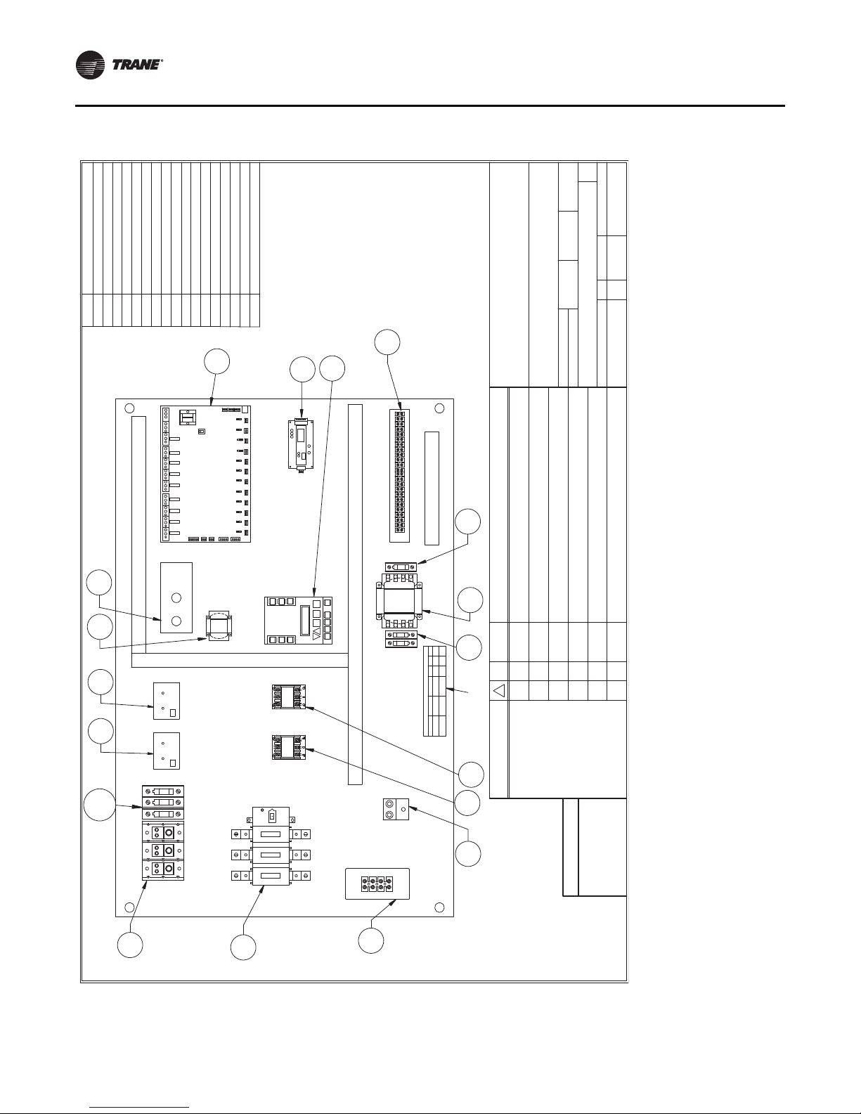
#
B
P.O. BOX 3066
LONGVIEW, TX
75606-3066
OF
APP'D BY:
CHECKED BY:
DRAWN BY:
DATE:
SCALE:
DWG. SIZE
TITLE:
NAPPS JOB NO.DRAWING NUMBER SHEET NO.REV.
TRANE.
WITHOUT THE EXPRESS WRITTEN CONSENT OF
OR USED FOR ANY PURPOSE
THIS MATERIAL MAY BE REPRODUCED
CONFIDENCE AND NO PORTION OF
MUST BE MAINTAINED IN STRICT
TRANE,
WHICH IS THE PROPERTY OF
THE INFORMATION CONTAINED HEREON,
IMPORTANT
NOISIVERETADLAES S'REENIGNEBY
CGWR SCROLL 410A
WATER-COOLED CHILLER
CONTROL PANEL LAYOUT
20 - 30 TON WATER-COOLED CHILLER 460V
NOITCUDORP 12000508R 11
8/11/17
NA
SMH
1
CLASS
CC
/
1
1
2
600
VOLTS
100-5564
600
DESIGNATION
FU1, FU2
FU3
AMPS
/
2
PRIMARY KLDR1
LITTELFUSE
KLDR3
TRANSFORMER
SECONDARY /
2
1
CC 3
/
1
2
TRANSFORMER FUSE SCHEDULE
FUSE TYPE
LITTELFUSETRANSFORMER
LOCATION
FOR 460V UNITS
1 - CPS On/Off
POWER DISTRIBUTION BLOCK
PDB1
208,240,480/120 VAC 250 VA TRANSFORMER
TR1
COMPRESSOR CONTACTORS
TR1 SECONDARY CIRCUIT FUSE - KLDR OR EQ
TR1 PRIMARY CIRCUIT FUSES - KLDR OR EQ
DISCONNECT SWITCH
FU1, FU2
FU3
DSW1
C1-C2
LEGEND
UNIT CONTROLLERUCCOMMUNICATIONS MODULE
COM
CURRENT TRANSFORMER MODULESCT1-CT2
120/24 VAC TRANSFORMER FOR WRVTR3
TR1
C1
GND
C2
FU1,2
DSW1
*
PDB1
CT1
CT2
FUSE
SCHEDULE
FU3
9
92143
214
3
756 8
7
56 8
1110 12131110 12 13
14 15 1716
14 15 17 226
1
221918 2120
19
18 2120
2423
24
23
1
2
BAR
2 - CKT1 Enable
SW
TBA
UC
TR3
*
UNIT CONTROLLER
115v
RELAY M-8
RELAY M-9
Voltage
RELAY M-7
RELAY M-3
RELAY M-6
RELAY M-5
RELAY M-4
RELAY M-1
RELAY M-2
RELAY M-10
PWM
*
COM
*
FU4-6
*
***
*
3A
*
TBC
3412
3412
GROUND LUG
TERMINAL BLOCKTBA
GND
TOOGLE SWITCHSW
TERMINAL BLOCK FOR WATER REGULATING VALVE
*
TBC
PWM
*
DIGITAL POWER MONITOR
SMH
ITEMS MARKED WITH * ARE OPTIONAL
AND ARE NOT ON ALL UNITS
WRV
TBA
PWM CIRCUIT FUSES - KTK OR EQFU4,5,6
0
Electrical Schematics
Figure 12. Control panel layout for 20 to 30 ton, 460V, R-410A CGWR water-cooled chillers
44 CG-SVX038A-EN
Page 45

Figure 13. Control panel layout for 20 to 30 ton, 575V, R-410A CGWR water-cooled chillers
#
B
P.O. BOX 3066
LONGVIEW, TX
75606-3066
OF
APP'D BY:
CHECKED BY:
DRAWN BY:
DATE:
SCALE:
DWG. SIZE
TITLE:
NAPPS JOB NO.DRAWING NUMBER SHEET NO.REV.
TRANE.
WITHOUT THE EXPRESS WRITTEN CONSENT OF
OR USED FOR ANY PURPOSE
THIS MATERIAL MAY BE REPRODUCED
CONFIDENCE AND NO PORTION OF
MUST BE MAINTAINED IN STRICT
TRANE,
WHICH IS THE PROPERTY OF
THE INFORMATION CONTAINED HEREON,
IMPORTANT
NOISIVERETADLAES S'REENIGNE BY
SCROLL 410A
WATER-COOLED CHILLER
CONTROL PANEL LAYOUT
20-30 TON WATER-COOLED CHILLER 575V
NOITCUDORP 22000508R 11
10/25/2011
1:1
PMK
600
DESIGNATION
FU1, FU2
FU3
AMPS
/
4
PRIMARY KLDR1
LITTELFUSE
KLDR3
TRANSFORMER
SECONDARY /
2
1
CC 3
/
1
2
TRANSFORMER FUSE SCHEDULE
FUSE TYPE
LITTELFUSE
TRANSFORMER
LOCATION
1
CLASS
CC
/
1
1
4
600
VOLTS
100-5564A
FOR 575V UNITS
GND
TERMINAL BLOCKTBA
POWER DISTRIBUTION BLOCK
PDB1
600 VAC 250 VA TRANSFORMER
TR1
COMPRESSOR CONTACTORS
TR1 SECONDARY CIRCUIT FUSE - KLDR OR EQ
TR1 PRIMARY CIRCUIT FUSES - KLDR OR EQ
DISCONNECT SWITCH
FU1, FU2
FU3
DSW1
C1-C2
LEGEND
UNIT CONTROLLER
UC
COMMUNICATIONS MODULE
COM
CURRENT TRANSFORMER MODULESCT1-CT2
120/24 VAC TRANSFORMER FOR WRVTR3
ITEMS MARKED WITH * ARE OPTIONAL
AND ARE NOT ON ALL UNITS
TR1
2143
TBC
*
2143
C1
GND
C2
FU1,2
DSW1
*
PDB1
CT1
CT2
FUSE
SCHEDULE
FU3
9
92143
2143
756 8
7
56 8
1110 12
13
1110 12 13
14 15 1716
14 15 17 2261
221918 21
20
1918 21
20
2423
2423
GROUND LUG
1
2
2 - CKT1 Enable
SW
TBA
UC
TR3
*
UNIT CONTROLLER
115v
RELAY M-8
RELAY M-9
Voltage
RELAY M-7
RELAY M-3
RELAY M-6
RELAY M-5
RELAY M-4
RELAY M-1
RELAY M-2
RELAY M-10
PWM
*
COM
*
FU4-6
*
***
*
PWM
*
DIGITAL POWER MONITOR
TERMINAL BLOCK FOR WATER REGULATING VALVETBC
TOOGLE SWITCHSW
1 - CPS On/Off
*
TBA
PWM CIRCUIT FUSES - KTK OR EQFU4,5,6
WRV
TBC
0
Electrical Schematics
CG-SVX038A-EN 45
Page 46

Electrical Schematics
/
1
2
TRANSFORMER FUSE SCHEDULE
FUSE TYPE
LITTELFUSETRANSFORMER
LOCATION
1
CLASS
CC
/
1
3
2
600
VOLTS
100-5563
600
DESIGNATION
FU1, FU2
FU3
AMPS
/
2
PRIMARY KLDR3
LITTELFUSE
KLDR3
TRANSFORMER
SECONDARY /
2
1
CC 3
FOR 208-230V UNITS
#
B
P.O. BOX 3066
LONGVIEW, TX
75606-3066
OF
APP'D BY:
CHECKED BY:
DRAWN BY:
DATE:
SCALE:
DWG. SIZE
TITLE:
NAPPS JOB NO.DRAWING NUMBER SHEET NO.REV.
TRANE.
WITHOUT THE EXPRESS WRITTEN CONSENT OF
OR USED FOR ANY PURPOSE
THIS MATERIAL MAY BE REPRODUCED
CONFIDENCE AND NO PORTION OF
MUST BE MAINTAINED IN STRICT
TRANE,
WHICH IS THE PROPERTY OF
THE INFORMATION CONTAINED HEREON,
IMPORTANT
NOISIVERETADLAES S'REENIGNEBY
SCROLL 410A
WATER-COOLED CHILLER
CONTROL PANEL LAYOUT 208/230V
40 - 65 TON WATER-COOLED CHILLER
NOITCUDORP 32000508R 11
9/26/13
1:1
SMH SMH BAR
0
1
FUSE SCHEDULE FOR 208-230V UNITS
DESIGNATION LOCATION FUSE TYPE CLASS AMPS VOLTS
FU1, FU2
PRIMARY
TRANSFORMER
CC 3 1/2 600
FU3
SECONDARY
TRANSFORMER
LITTELFUSE
KLDR3
2
1
CC 3 1/2 600
FU4, FU5, FU6 *
DIGITAL POWER
MONITOR *
0
061
1K
T
K
N
O
R
TIMI
L
LITTELFUSE
KLDR3
2
NOTES:
1. ITEMS MARKED WITH * ARE OPTIONAL
AND ARE NOT ON ALL UNITS.
23
FU4-6
230V
TR1
FU3
SCHEDULE
FUSE
SW
21
*
PWM
C2
FU1,2
C3C1
GND
DSW1
*
CT3
CT2CT1
PDB1
TBA
TR3
23
EXP1
UC
3 - CKT2 Enable
RELAY M-1
RELAY M-2
RELAY M-3
UNIT CONTROLLER
RELAY M-5
RELAY M-4
RELAY M-6
RELAY M-8
RELAY M-7
RELAY M-9
Voltage
115v
RELAY M-10
3
TBC
*
3421
3421
COM
*
9
92
143
2143
7
56 8
756 8
1110 121311
10 12 13
14 15 171614 15 17
2261
22
19
18 2120
1918 2120
24
*
24
1 - CPS On/Off
2 - CKT1 Enable
*
GND
*
*
POWER DISTRIBUTION BLOCK
PDB1
208,240,480/120 VAC 250 VA TRANSFORMER
TR1
COMPRESSOR CONTACTORS
TR1 SECONDARY CIRCUIT FUSE - KLDR OR EQ
TR1 PRIMARY CIRCUIT FUSES - KLDR OR EQ
DISCONNECT SWITCH
FU1, FU2
FU3
DSW1
C1-C3
LEGEND
UNIT CONTROLLERUCCOMMUNICATIONS MODULE
COM
CURRENT TRANSFORMER MODULESCT1-CT3
*
*
120/24 VAC TRANSFORMER FOR WRVTR3
TBC
WRV
DIGITAL POWER MONITOR PWM
*
EXPANSION BOARD SI 16-A04EXP1
TBA
TOGGLE SWITCHESSW
TERMINAL BLOCKTBA
TERMINAL BLOCK FOR WATER REGULATING VALVETBC
PWM CIRCUIT FUSES - KTK OR EQFU4,5,6
GROUND LUG
*
Figure 14. Control panel layout for 40 to 65 ton, 208V, R-410A CGWR water-cooled chillers
46 CG-SVX038A-EN
Page 47

Figure 15. Control panel layout for 40 to 65 ton, 460V, R-410A CGWR water-cooled chillers
FUSE TYPE
LITTELFUSE
TRANSFORMER
LOCATION
1
CLASS
CC
/
1
1
2
600
VOLTS
100-5564
600
DESIGNATION
FU1, FU2
FU3
AMPS
/
2
PRIMARY KLDR1
LITTELFUSE
KLDR3
TRANSFORMER
SECONDARY /
2
1
CC 3/
1
2
TRANSFORMER FUSE SCHEDULE
FOR 460V UNITS
#
B
P.O. BOX 3066
LONGVIEW, TX
75606-3066
OF
APP'D BY:
CHECKED BY:
DRAWN BY:
DATE:
SCALE:
DWG. SIZE
TITLE:
NAPPS JOB NO.DRAWING NUMBER SHEET NO.REV.
TRANE.
WITHOUT THE EXPRESS WRITTEN CONSENT OF
OR USED FOR ANY PURPOSE
THIS MATERIAL MAY BE REPRODUCED
CONFIDENCE AND NO PORTION OF
MUST BE MAINTAINED IN STRICT
TRANE,
WHICH IS THE PROPERTY OF
THE INFORMATION CONTAINED HEREON,
IMPORTANT
ENGINEER'S SEAL DATE
REVISION
BY
CGWR SCROLL 410A
WATER-COOLED CHILLER
CONTROL PANEL LAYOUT
40-65 TON WATER-COOLED CHILLER 460V
NOITCUDORP 42000508R 11
9/27/13
1:1
SMH SMH BAR
0
1
FUSE SCHEDULE FOR 460V UNITS
DESIGNATION LOCATION FUSE TYPE CLASS AMPS VOLTS
FU1, FU2
PRIMARY
TRANSFORMER
LITTELFUSE KLDR1
2
1
CC 1 1/2 600
FU3
SECONDARY
TRANSFORMER
LITTELFUSE
KLDR3
2
1
CC 3 1/2 600
FU4, FU5, FU6 *
DIGITAL POWER
MONITOR *
0061KTK NORTIMIL
NOTES:
1. ITEMS MARKED WITH * ARE OPTIONAL
AND ARE NOT ON ALL UNITS.
*
FU4-6
230V
TR1
FU3
SCHEDULE
FUSE
SW
21
*
PWM
C2
FU1,2
C3C1
GND
DSW1
*
CT3
CT2CT1
PDB1
TBA
TR3
23
EXP1
UC
3 - CKT2 Enable
RELAY M-1
RELAY M-2
RELAY M-3
UNIT CONTROLLER
RELAY M-5
RELAY M-4
RELAY M-6
RELAY M-8
RELAY M-7
RELAY M-9
Voltage
115v
RELAY M-10
3
TBC
*
3421
3421
COM
*
9
92
143
2143
7
56 8
756 8
1110 121311
10 12 13
14 15 171614 15 17
2261
22
19
18 2120
1918 2120
242324
1 - CPS On/Off
2 - CKT1 Enable
*
*
*
*
POWER DISTRIBUTION BLOCK
PDB1
208,240,480/120 VAC 250 VA TRANSFORMER
TR1
COMPRESSOR CONTACTORS
TR1 SECONDARY CIRCUIT FUSE - KLDR OR EQ
TR1 PRIMARY CIRCUIT FUSES - KLDR OR EQ
DISCONNECT SWITCH
FU1, FU2
FU3
DSW1
C1-C3
LEGEND
UNIT CONTROLLERUCCOMMUNICATIONS MODULE
COM
CURRENT TRANSFORMER MODULESCT1-CT3
*
*
120/24 VAC TRANSFORMER FOR WRV
TBC
WRV
DIGITAL POWER MONITOR PWM*EXPANSION BOARD SI 16-A04EXP1
TBA
TOGGLE SWITCHESSW
TERMINAL BLOCKTBA
TERMINAL BLOCK FOR WATER REGULATING VALVE
TBC
PWM CIRCUIT FUSES - KTK OR EQFU4,5,6
GROUND LUGGND
TR3
Electrical Schematics
CG-SVX038A-EN 47
Page 48
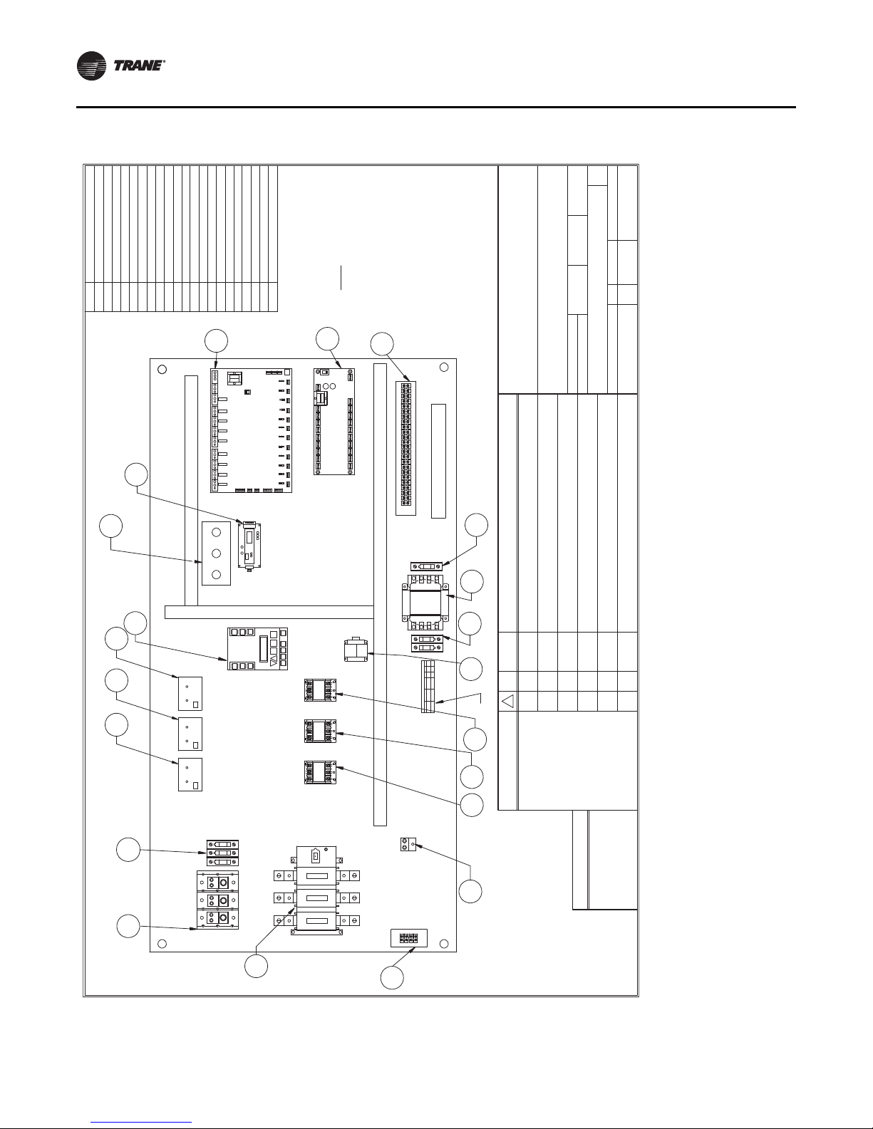
2
1
CC 3/
1
2
TRANSFORMER FUSE SCHEDULE
FUSE TYPE
LITTELFUSETRANSFORMER
LOCATION
1
CLASS
CC
/
1
1
4
600
VOLTS
100-5564
600
DESIGNATION
FU1, FU2
FU3
AMPS
/
4
PRIMARY KLDR1
LITTELFUSE
KLDR3
TRANSFORMER
SECONDARY /
FOR 460V UNITS
#
B
P.O. BOX 3066
LONGVIEW, TX
75606-3066
OF
APP'D BY:
CHECKED BY:
DRAWN BY:
DATE:
SCALE:
DWG. SIZE
TITLE:
NAPPS JOB NO.DRAWING NUMBER SHEET NO.REV.
TRANE.
WITHOUT THE EXPRESS WRITTEN CONSENT OF
OR USED FOR ANY PURPOSE
THIS MATERIAL MAY BE REPRODUCED
CONFIDENCE AND NO PORTION OF
MUST BE MAINTAINED IN STRICT
TRANE,
WHICH IS THE PROPERTY OF
THE INFORMATION CONTAINED HEREON,
IMPORTANT
NOISIVERETADLAES S'REENIGNEBY
SCROLL 410A
WATER-COOLED CHILLER
CONTROL PANEL LAYOUT
40-65 TON WATER-COOLED CHILLER 575V
NOITCUDORP 52000508R 11
9/27/13
1:1
SMH SMH BAR
NOTES:
1. ITEMS MARKED WITH * ARE OPTIONAL
AND ARE NOT ON ALL UNITS.
TBA
FU4-6
230V
TR1
FU3
SCHEDULE
FUSE
SW
21
*
PWM
C2
FU1,2
C3C1
GND
DSW1
*
CT3
CT2
CT1
PDB1
*
TR3
23
EXP1
UC
3 - CKT2 Enable
RELAY M-1
RELAY M-2
RELAY M-3
UNIT CONTROLLER
RELAY M-5
RELAY M-4
RELAY M-6
RELAY M-8
RELAY M-7
RELAY M-9
Voltage
115v
RELAY M-10
3
TBC
*
3421
3421
COM
*
9
92
143
2143
7
56 8
756 8
1110 121311
10 12 13
14 15 171614 15 17
2261
22
19
18 2120
1918 2120
242324
1 - CPS On/Off
2 - CKT1 Enable
*
*
*
*
POWER DISTRIBUTION BLOCK
PDB1
600 VAC 250 VA TRANSFORMER
TR1
COMPRESSOR CONTACTORS
TR1 SECONDARY CIRCUIT FUSE - KLDR OR EQ
TR1 PRIMARY CIRCUIT FUSES - KLDR OR EQ
DISCONNECT SWITCH
FU1, FU2
FU3
DSW1
C1-C3
LEGEND
UNIT CONTROLLERUCCOMMUNICATIONS MODULE
COM
CURRENT TRANSFORMER MODULESCT1-CT3
*
*
120/24 VAC TRANSFORMER FOR WRVTR3
TBC
WRV
DIGITAL POWER MONITOR
PWM
*
EXPANSION BOARD SI 16-A04EX P1
TBA
TOGGLE SWITCHESSWTERMINAL BLOCKTBA
TERMINAL BLOCK FOR WATER REGULATING VALVETBC
PWM CIRCUIT FUSES - KTK OR EQ
FU4,5,6
GROUND LUG
GND
0
Electrical Schematics
Figure 16. Control panel layout for 40 to 65 ton, 575V, R-410A CGWR water-cooled chillers
48 CG-SVX038A-EN
Page 49

CCAR Compressor Chillers
UNIT CONTROLLER
21
4
43
2
1
GROUND
(Factory Installed)
PDB1
L1
L2
L3
9
PANEL
Disconnect
Damper Control
23
24
23 24
20
2118 19
20 2118 19 22
22
16 17
15
14
16 171514
13
12
10 11
131210 11
86
5
7
8657
3
Optional:
Optional:
9
Optional
DSW1
A-1
A-2
GND
A-1
WARNING
A-2
6
Disconnect all electrical power
Hazardous voltage!
4
Condensing Unit Fan 1
GND
5
TBA
Control Panel Representation
Condensing Unit Control Power
Interface
: Alarm Dry
Contacts
4
REQUIRED
: Flow Switch (flow
Condensing Unit Fan 2
: Remote Run/Stop
proving device)
Optional
including remote disconnects before
5
indoor chiller.
CAUTION
Do not energize the unit until checkout and start-up procedures have
been completed.
Wiring to be 2-wire shielded cable between outdoor unit and Trane
If installing with a Trane CAUJ air-cooled condenser, more specific
7.
field wiring instructions can be found in the operations and
maintenance manual.
Use copper conductors only!
CAUTION
Failure to do so can cause death or
equipment damage.
to use copper conductors may cause
accept other type conductors. Failure
Unit terminals are not designed to
serious injury.
cannot be inadvertently energized.
tagout procedures to ensure power
servicing unit. Follow proper lockout/
Notes
:
All three-phase motors supplied with the unit are protected under
1.
primary single-phase failure conditions.
All customer control-circuit wiring must have a minimum rating of
2.
150V.
All field wiring must be in accordance with applicable local codes.
3.
Line voltage options. Single or dual source power may be specified.
4.
Drawing covers single source power only. All field wiring must be in
accordance with National Electric Code and State & Local
requirements.
(Required) Factory supplied or approved alternate field installed flow
5.
proving device connection.
(Optional) Damper control option. Refer to operation and
6.
maintenance manual for additional information. This point intended to
operate a low ambient damper on a remote air-cooled condenser.
6
Condensing Unit Fan 3
Field Wiring Single Circuit CCAR
0
WEIGHT:
SIZE
DWG. NO.
A
REV.
NAME
DATE
DRAWN
CHECKED
ENG APPR.
MFG APPR.
Q.A.
SMH
3/22/17
SHEET 1 OF 1
COMMENTS:
Diagram
BAR
3/22/17
CCAR 20-30 Ton
Field Wiring
SCALE:1:5
CCAR Field Wiring
Figure 17. Field wiring diagram for 20 to 30 ton, R-410A CCAR compressor chillers
Electrical Schematics
CG-SVX038A-EN 49
Page 50

Electrical Schematics
Dual Circuit CCAR Field Wiring
0
WEIGHT:
SIZE
DWG. NO.
A
REV.
NAME
DATE
DRAWN
CHECKED
COMMENTS:
MFG APPR.
Q.A.
BAR
3/23/17
SMH
SHEET 1 OF 1
ENG APPR.
Diagram
3/23/17
CCAR 40-65 Ton
Field Wiring
SCALE:1:5
7
L2
UNIT CONTROLLER
L3
9382
GROUND
(Factory Installed)
PDB1
L1
7
TBD
6
PANEL
Disconnect
Damper Control
23
24
23 24
20
2118 19
20 2118 19 22
22
16 17
15
14
16 171514
13
12
10 11
131210 11
86
5
1
8657
3412
34 921
9
59
4375
842
6
Optional:
Optional:
1
DSW1
A-1
A-2
GND
A-1
WARNING
A-2
Circuit 1 Fan 2
6
Disconnect all electrical power
Hazardous voltage!
4
Circuit 2 Fan 1
GND
5
TBA
Control Panel Representation
servicing unit. Follow proper lockout/
including remote disconnects before
Condensing Unit Control Power
Optional
Interface
: Alarm Dry
Contacts
4
REQUIRED
: Flow Switch (flow
Circuit 1 Fan 1
: Remote Run/Stop
5
proving device)
tagout procedures to ensure power
Optional
unit and Trane indoor chiller.
CAUTION
Do not energize the unit until checkout and start-up procedures have
been completed.
damper per AO. Wiring to be 2-wire shielded cable between outdoor
If installing with a Trane CAUJ air-cooled condenser, more specific
7.
field wiring instructions can be found in the operations and
maintenance manual.
Use copper conductors only!
CAUTION
Failure to do so can cause death or
equipment damage.
to use copper conductors may cause
accept other type conductors. Failure
Unit terminals are not designed to
serious injury.
cannot be inadvertently energized.
Notes
:
All three-phase motors supplied with the unit are protected under
1.
primary single-phase failure conditions.
All customer control-circuit wiring must have a minimum rating of
2.
150V.
All field wiring must be in accordance with applicable local codes.
3.
Line voltage options. Single or dual source power may be specified.
4.
Drawing covers single source power only. All field wiring must be in
accordance with National Electric Code and State & Local
requirements.
(Required) Factory supplied or approved alternate field installed flow
5.
proving device connection.
(Optional) Damper control option. Refer to operation and
6.
maintenance manual for additional information. This point intended to
operate low ambient dampers on a remote air-cooled condenser, (1)
6
Circuit 2 Fan 2
Circuit 1 Fan 3
Circuit 2 Fan 3
Figure 18. Field wiring diagram for 40 to 65 ton, R-410A CCAR compressor chillers
50 CG-SVX038A-EN
Page 51

Electrical Schematics
#
B
LONGVIEW, TX
75606-3066
P.O. BOX 3066
OF
APP'D BY:
CHECKED BY:
DRAWN BY:
DATE:
SCALE:
DWG. SIZE
TITLE:
NAPPS JOB NO.DRAWING NUMBER SHEET NO.REV.
TRANE.
WITHOUT THE EXPRESS WRITTEN CONSENT OF
OR USED FOR ANY PURPOSE
THIS MATERIAL MAY BE REPRODUCED
CONFIDENCE AND NO PORTION OF
MUST BE MAINTAINED IN STRICT
TRANE,
WHICH IS THE PROPERTY OF
THE INFORMATION CONTAINED HEREON,
IMPORTANT
NOISIVERETADLAES S'REENIGNE
BY
R410 CCAR COMPRESSOR CHILLERS
POWER/CONTROL WIRING SCHEMATIC
20 - 30 TON COMPRESSOR CHILLER
11
08/03/17
HMSHMS
0
3F1F F2
+5 GND SI
+ - GND
R80500013
1211
11 12
BAR
(CT 1)
(CT 2)
POWER IN
TBA7
3G
3G
HP1SW
BLACK
WHITE
SHIELD
WHITE
WHITE
LIQUID SOLENOID
LLS 1
RELAY M-1
C1
LLS 1
RELAY M-2
RELAY M-4
SPARE
HGS 1
RELAY M-3
SPARE
RELAY M-5
RELAY M-7
FAN 1
C2
RELAY M-6
GNDNL/L1
BLACK
WHITE
SHIELD
SENSOR M-11
CKT 1 SUC TMP
AMPS COMP 2
SENSOR M-6
SENSOR M-5
AMPS COMP 1
CKT 1 DIS PSI
SENSOR M-4
SENSOR M-3
CKT 1 SUC PSI
CW OUT
SENSOR M-2
+5 GND SI
+5 GND SI
+5 GND SI
+5 GND SI
+5 GND SI
+5 GND SI
+5 GND SI
+5 GND SI
+5 GND SI
+5 GND SI
DIGITAL ANALOG
DIGITAL ANALOG
DIGITAL ANALOG
DIGITAL ANALOG
DIGITAL ANALOG
DIGITAL ANALOG
DIGITAL ANALOG
DIGITAL ANALOG
DIGITAL ANALOG
DIGITAL ANALOG
WHITE
RED
BLACK & SHIELD
DIGITAL ANALOG
+5 GND SI
SENSOR M-1
CW IN
DIGITAL ANALOG
Termination
HGS 1
HOT GAS SOLENOID
LP1SW
TBA10
TBA11
TBA20
RED 3
UNIT CONTROLLER
FLOW-Field
SENSOR M-16
REM RUN/STOP
CMP1&2 ENABLE
V+
L
(OPTIONAL TOUCHSCREEN
DAMPER CONTROL
TO KEYPAD / DISPLAY
Com NO NC
(Shield tied at this end)
ETHERNET
+12VMCS IORS485
SENSOR 12
SENSOR 11
SENSOR 10
SENSOR 9
SENSOR 8
SENSOR 7
SENSOR 5
SENSOR 6
SENSOR 3
SENSOR 4
SENSOR 1
SENSOR 2
DI-15DI-16 DI-13DI-14
+5+5
+5
DIGITAL INPUTS
ANALOG OUTS
A-3A-4 A-1A-2
gnd
gnd
-485
+485
SCL
SDA
GND
+12V
KEYPAD LCD
115v
Voltage
Com NO NC
Com NO NCCom NO NCCom NO NCCom NO NCCom NO NCCom NO NCCom NO NCCom NO NC
19
20
9
8
6
7
TBA6
3D
TBA19
17
TBA17
TBA18
18
TBA1616TBA15
15
5B
C2
Comp 2
Comp 1
C1
44A
TBA1
TBA2
3A
TBA4
5A
5
3
TBA3
TBA24
TBA23
TBA22
TBA21
RELAY M-8
RELAY M-9
RELAY M-10
ALARM
FAN 3
7A
8A
CONTACTOR
CONTACTOR
+5
24
23
22
21
SENSOR M-14
OPT PWM
PWR MONITOR
SHIELD
BLACK &
BLACK
SHIELD
WHITE
To Optional Exp Board
Comm to SI16 or eq
WHITE
3
3A
OPTIONAL FIELD
FAN 2
SHIELD
BLACK/
SHIELD
WHITE
RED
BLACK & SHIELD
BLACK &
SHIELD
WHITE
120 VAC
FU1
FU2
FU3
21
RED
WHITE
TR1
T3T2T1
L3
C1
L2L1
L3L2
C2
L1
MOTOR
C2 AUX 2 CCH 2
COMPRESSOR
T3T1 T2
CCH 1
SENSOR M-13
SENSOR M-15
OPTIONAL
COMPRESSOR
MOTOR
2
COMPR
L3
L2L1
PDB1
DSW1
DISCONNECT
(OPTIONAL)
L1
L3
PWM
L2
(OPTIONAL)
FU4 FU5 FU6
GROUND
PANEL
SHIELD
SENSOR M-12
CORE TEMP
BLACK
WHITE
COMPR
C1 AUX 1
1
15B
15A
Optional Touchscreen
To Customer Interface or
TO UNIT
CONNECTOR
-485
+485
SDA
SCL
Gnd
+12v
32
6
4
1
5
7
8
Menu
Communications Board or
CONTOLLER
KEYPAD/LCD
POWER SOURCE)
ETHERNET
GND
N
+12V GND ??
(OPTIONAL TOUCHSCREEN CONNECTIONS)
or Ethernet SwitchV-To Unit Controller
Ethernet Connection
TBA5
CCAR Power/Control Wiring
Refer to name plate on control box door (inside) for
electrical data and wiring diagram.
Figure 19. Power/control wiring schematic for 20 to 30 ton, R-410A CCAR compressor chillers
CG-SVX038A-EN 51
Page 52

Electrical Schematics
#
B
LONGVIEW,TX
75606-3066
P.O. BOX 3066
OF
APP'D BY:
CHECKED BY:
DRAWN BY:
DATE:
SCALE:
DWG. SIZE
TITLE:
NAPPS JOB NO.DRAWING NUMBER SHEET NO.REV.
TRANE.
WITHOUT THE EXPRESS WRITTEN CONSENT OF
OR USED FOR ANY PURPOSE
THIS MATERIAL MAY BE REPRODUCED
CONFIDENCE AND NO PORTION OF
MUST BE MAINTAINED IN STRICT
TRANE,
WHICH IS THE PROPERTY OF
THE INFORMATION CONTAINED HEREON,
IMPORTANT
NOISIVERETADLAES S'REENIGNE
BY
R410 CCAR COMPRESSOR CHILLERS
POWER/CONTROL WIRING SCHEMATIC
40 - 65 TON COMPRESSOR CHILLER
11
HMSHMS71/72/70
0
E
X
P
A
N
S
IO
N
B
O
A
R
D
IN
T
E
R
F
A
C
E
(CT 1)
(CT 3)
(CT 2)
+5 GND SI
+ - GND
R80500014
1211
11
12
F2
F3F1
1211
}
BAR
}
NC NO COMNC NO COM
NC NO COMNC NO COMNC NO COM
COM NO NCCOM NO NCCOM NO NC
COM NO NC
COM NO NC
POWER IN
CKT1 FAN2
To Customer Interface or
3G
HP1SW
K
E
Y
P
A
D
L
C
D
C
O
N
N
E
C
T
O
R
T
O
U
N
I
T
C
O
N
T
R
O
L
L
E
R
BLACK
WHITE
SHIELD
WHITE
WHITE
LIQUID SOLENOID
LLS 1
RELAY M-1
C1
LLS 1
RELAY M-2
RELAY M-4
C2
SPARE
RELAY M-3
LLS 2
RELAY M-5
RELAY M-7
C3
HGS 2
RELAY M-6
GND
N
L/L1
BLACK
WHITE
SHIELD
SENSOR M-11
CKT 1 SUC TMP
AMPS COMP 3
SENSOR M-6
SENSOR M-5
AMPS COMP 1
CKT 1 DIS PSI
SENSOR M-4
SENSOR M-3
CKT 1 SUC PSI
CW OUT
SENSOR M-2
+5 GND SI
+5 GND SI
+5 GND SI
+5 GND SI
+5 GND SI
+5 GND SI
+5 GND SI
+5 GND SI
+5 GND SI
+5 GND SI
DIGITAL ANALOG
DIGITAL ANALOG
DIGITAL ANALOG
DIGITAL ANALOG
DIGITAL ANALOG
DIGITAL ANALOG
DIGITAL ANALOG
DIGITAL ANALOG
DIGITAL ANALOG
DIGITAL ANALOG
WHITE
RED
BLACK & SHIELD
DIGITAL ANALOG
+5 GND SI
SENSOR M-1
CW IN
DIGITAL ANALOG
Termination
LP1SW
TBA10
TBA20
RED 3
UNIT CONTROLLER
FLOW-Field
SENSOR M-16
REM RUN/STOP
CMP1&3 ENABLE
SENSOR M-13
SENSOR M-15
Com NO NC
ETHERNET
+12VMCS IORS485
SENSOR 12
SENSOR 11
SENSOR 10
SENSOR 9
SENSOR 8
SENSOR 7
SENSOR 5
SENSOR 6
SENSOR 3
SENSOR 4
SENSOR 1
SENSOR 2
DI-15DI-16 DI-13DI-14
+5+5
+5
DIGITAL INPUTS
ANALOG OUTS
A-3A-4 A-1A-2
gnd
gnd
-485
+485
SCL
SDA
GND
+12V
KEYPAD LCD
115v
Voltage
Com NO NC
Com NO NCCom NO NCCom NO NCCom NO NCCom NO NCCom NO NCCom NO NCCom NO NC
19
20
9
6
7
TBA6
3D
3
TBA19
5B
C3
CKT1 Comp 3
CKT 1 Comp 1
C1
44A
TBA1
TBA2
3A
TBA7
5A
5
3
TBA3
TBA24
TBA23
TBA22
TBA21
RELAY M-8
RELAY M-9
RELAY M-10
ALARM
7A
CONTACTOR
CONTACTOR
+5
24
23
22
21
SENSOR M-14
SPARE
SENSOR M-10
AMPS COMP 2
SENSOR M-9
SHIELD
BLACK &
BLACK
SHIELD
WHITE
3
3A
OPTIONAL FIELD
SHIELD
BLACK/
SHIELD
WHITE
RED
BLACK & SHIELD
BLACK &
SHIELD
WHITE
120 VAC
FU1
FU2
FU3
21
RED
WHITE
TR1
T3T2T1
L3
C1
L2L1
C3
C1 AUX 1
CCH 1
T3T1
(OPTIONAL TOUCHSCREEN
POWER SOURCE)
L
T2
CCH 3
3
COMPR
CKT 1
L3
L2L1
PDB1
DSW1
DISCONNECT
(OPTIONAL)
(OPTIONAL)
GROUND
PANEL
Menu
8
7
5
1
4
6
2
3
+12v
Gnd
SCL
SDA
+485
-485
T3T2
COMPR
C3 AUX 3
1
COMPR
CKT 2
C2 AUX 2
CCH 2
L3L2L1
L3L2L1
COMPRESSOR
MOTOR
COMPRESSOR
MOTOR
COMPRESSOR
MOTOR
MTR MOD 2
BLUE
YELLOW
11B
LIQUID SOLENOID
LLS 2
TBA12
13A
13
C2
CKT2 Comp 2
CONTACTOR
12
SENSOR 2-8
SENSOR 1-8
120 VAC POWER IN
+ - GND
LINE NEUT GND
6
8
7
1
5
3
4
2
ADDRESS
Termination
MCS I/O
BLACK
WHITE
SPARE2-8
TRANSFORMER
SPARE1-8
BLACK
+5 GND SI
ANALOG
SPARE2-6
SENSOR 2-7
SPARE2-7
SPARE2-5
SENSOR 2-6
SENSOR 2-5
MTR MOD 2
SPARE2-4
SENSOR 2-4
SENSOR 2-3
SPARE2-2
SENSOR 2-2
SPARE2-1
SENSOR 2-1
DIGITAL
SHIELD
WHITE
SPARE 1-6
SPARE 1-7
SENSOR 1-7
SENSOR 1-6
SENSOR 1-5
SPARE 1-5
SPARE 1-4
CORE TEMP
SENSOR 1-4
SENSOR 1-3
SENSOR 1-2
TRGT RST
PWR MONITOR
SENSOR 1-1
Optional
Optional
COM
ALARM
SENSOR 9
+5 GND SI
ANALOG
DIGITAL
SENSOR 10
+5 GND SI
ANALOG
DIGITAL
SENSOR 11
+5 GND SI
ANALOG
DIGITAL
SENSOR 12
+5 GND SI
ANALOG
DIGITAL
SENSOR 13
+5 GND SI
ANALOG
DIGITAL
SENSOR 14
+5 GND SI
ANALOG
DIGITAL
SENSOR 15
+5 GND SI
ANALOG
DIGITAL
SENSOR 16
ANALOG
DIGITAL
ANALOG
DIGITAL
ANALOG
DIGITAL
ANALOG
DIGITAL
ANALOG
DIGITAL
ANALOG
DIGITAL
ANALOG
DIGITAL
ANALOG
DIGITAL
ANALOG
DIGITAL
+12 +12 +12
SI GND +5
SENSOR 2
SENSOR 3
SENSOR 4
SENSOR 5
SENSOR 6
SENSOR 7
SENSOR 8
SENSOR 1
To SI Board
11A
TBA9
11
3C
HP2SW
LP2SW
TBA8
1010A
3E
CKT 2 SUC PSI
SENSOR M-7
CKT 2 DIS PSI
SENSOR M-8
WHITE
RED
BLACK & SHIELD
WHITE
RED
BLACK & SHIELD
BLACK
WHITE
SHIELD
SENSOR M-12
CKT 2 SUC TMP
CONTROL PWR SWITCH
ON/OFF
WHITE
WHITE
3C
WHITE
TBA2
T1
C2
2
DAMPER CONTROL
TO KEYPAD / DISPLAY
CMP2 ENABLE
WHITE
SHIELD
BLACK &
BLACK
SHIELD
WHITE
HGS 1
HOT GAS SOLENOID
HGS 1
8A
TBA11
FU6
FU5FU4
L2
PWM
L3
L1
RO 10
RO 9
RO 8
RO 7
RO 6
RO 5
RO 4
RO 3
RO 2
TRANSFORMER
RO 1
+ - GND
MCS I/O
Termination
ADDRESS
5
7
8
6
2
4
3
1
RO10
LINE NEU
L1 L2
115V
GND
3B
W
H
I
T
E
TBA5 TBA1
TBD3TBD6
28
TBD4
27
TBD2
26
31
TBD7
25
TBD1
SI GND +5 SI GND +5
SI GND +5
SI GND +5
SI GND +5
SI GND +5
SI GND +5
8
TBA18
17
TBA17
18
16A
HGS 2
TBA13
16
HOT GAS SOLENOID
SPARE
32
TBD8
Optional Touchscreen
CKT1 FAN1
30
CKT1 FAN3CKT2 FAN1
CKT2 FAN2CKT2 FAN3
JUMPERS
A1 GND A2
ANALOG OUTPUTS
A3 GND A4
WHITE
BLACK
SHIELD
TBA-4
TBA-2
24 VAC
TR3
120 VAC
TBA3
V-
RED 3H
WHITE
or Ethernet Switch
(OPTIONAL TOUCHSCREEN CONNECTIONS)
+12V GND ??
ETHERNET
V+
To SI Board
OPTIONAL
Ethernet ConnectionNTo Unit Controller
Communications Board or
3G
Figure 20. Power/control wiring schematic for 40 to 65 ton, R-410A CCAR compressor chillers
52 CG-SVX038A-EN
Page 53

Figure 21. Power schematic, CAUJ condenser control circuit modification:
1TB2-1
34
1TB3-5
64
1TB3-4
63
1TB3-6
65
C
A
E
C
D
A
B
C
D
B
GG
1TB3-9
A
76
EE
E
1TB3-10
77
FF
C
1TB3-11
78
fan cycling control by CCAR compressor chillers
Electrical Schematics
CG-SVX038A-EN 53
Page 54

Electrical Schematics
A
Instructions
Circle
Remove wire 65C and/or the jumper installed. Connect 1TB3-6 to TBD 3 at Trane Chiller.
Remove wire 64E. Connect 1TB3-5 to TBD 2 at Trane Chiller. This is the first fan on and last fan off.
NOTES:
2
3
1
Remove wire 63A. Connect 1TB3-4 to TBD 4 at Trane Chiller. This is the last fan on and
Ambient t-stat will not be used. This is the second fan on and second fan off.
D
B
2
4
Remove wire 63A. Connect 1TB3-4 to TBA 18 at Trane Chiller. This is the last fan on and
Circle
Instructions
1
Step
Remove wire 64E. Connect 1TB3-5 to TBA 16 at Trane Chiller. This is the first fan on and last fan off.
Reference
Ambient t-stat will not be used. This is the second fan on and second fan off.
C
COMPLETE
Reference
Connect 1TB2-1 to TBA 15 at Trane Chiller.
Remove wire 65C and/or the jumper installed. Connect 1TB3-6 to TBA 17 at Trane Chiller.
first fan off. The installed pressure switch will not be used.
3
Step
1
1
3
B
Connect 1TB2-1 to TBA 15 at Trane Chiller.
D
2
first fan off. The installed pressure switch will not be used.
Circle
Remove wire 64E. Connect 1TB3-5 to TBA 16 at Trane Chiller. This is the first fan on and last fan off.
A
FOR CONTROL OF 3 FAN CONDENSER:
FOR CONTROL OF 2 FAN CONDENSER:
E
Connect 1TB2-1 to TBD 1 at Trane Chiller.
5
B
Instructions
C
Step
Initial/Date
Initial/Date
B
from the CCAR Compressor Chiller to the CAUJ condenser.
Initial/Date
FOR CONTROL OF 4 FAN CONDENSER:
COMPLETE
A
E
Connect 1TB2-1 to TBD 1 at Trane Chiller.
D
5
3
Remove wire 77E. Connect 1TB3-10 to TBD 6 at Trane Chiller.This is the first fan on and last fan off.
CCAR units are designed for operation down to a minimum of 40°F ambient.
first fan off. The installed pressure switch will not be used.
A
Instructions
Reference
The installed pressure switch will not be used.
Remove wire 64E. Connect 1TB3-5 to TBD 2 at Trane Chiller. This is the first fan on and last fan off.
COMPLETE
Circle
Remove wire 76A. Connect 1TB3-9 to TBD 7 at Trane Chiller. This is the last fan on and first fan off.
first fan off. The installed pressure switch will not be used.
Step
Remove wire 63A. Connect 1TB3-4 to TBA 17 at Trane Chiller. This is the second fan on and
Remove wire 63A. Connect 1TB3-4 to TBD 3 at Trane Chiller. This is the last fan on and
4
2
COMPLETE
Ambient t-stat will not be used. This is the second fan on and second fan off.
Remove wire 77E. Connect 1TB3-10 to TBD 6 at Trane Chiller. This is the first fan on and last fan off.
G7
Initial/Date
FOR CONTROL OF 6 FAN CONDENSER:
Remove wire 78C and/or the jumper installed. Connect 1TB3-11 to TBD 7 at Trane Chiller.
The installed pressure switch will not be used.
F6
Remove wire 76A. Connect 1TB3-9 to TBD 8 at Trane Chiller. This is the last fan on and first fan off.
G
D
All CCAR/CAUJ applications require that the CCAR Compressor Chiller control the condenser fan cycling.
For Fan Cycling Control - One control wire for each condenser fan plus a common must be run
Reference
4
CAUJ Condenser Control
Wiring Modification:
Fan Cycling Control by CCAR
Compressor Chillers
Trane CAUJ Condenser Control Wiring Modification
Fan Cycling Control by Trane CCAR Compressor Chillers
A
THREE PLACE DECIMAL
JOB #:
09/19/13
09/19/13
TRANE. ANY REPRODUCTION IN PART
R80500015B
LAH
09/19/13
DRAWING IS THE SOLE PROPERTY OF
BAR
EGN
SCALE:1:1
DWG. NO.
09/19/13
REV.
OR AS A WHOLE WITHOUT THE WRITTEN
75606-3066
PERMISSION OF TRANE IS PROHIBITED.
COMMENTS:
SHEET 1 OF 1
Q.A.
MFG APPR.
ENG APPR.
CHECKED
DRAWN
PROPRIETARY AND CONFIDENTIAL
THE INFORMATION CONTAINED IN THIS
DO NOT SCALE DRAWING
SIZE
SMH
NAME
MATERIAL
DATE
FINISH
DIMENSIONS ARE IN INCHES
TOLERANCES:
FRACTIONAL
ANGULAR: MACH BEND
TWO PLACE DECIMAL
LONGVIEW, TX
P.O. BOX 3066
Figure 22. Instructions — CAUJ condenser control circuit modification:
fan cycling control by CCAR compressor chillers
54 CG-SVX038A-EN
Page 55

Figure 23. Low ambient damper schematic wiring and connections diagrams —
839
851
9
3
(-) J2-3
P2-3 848A
2TB34-9
851
2TB34-10
A
10
839
C
A
B
F
B
2U83
(+) J2-4
P2-4 849A
851A
839F
B
P2
CJ2C
2U83
A
A
F
A
2TB34
Low Ambient Schematic Wiring Diagram
Low Ambient Connections Diagram
CAUJ condenser control circuit modification: low ambient damper control by CCAR compressor chillers
Electrical Schematics
CG-SVX038A-EN 55
Page 56
Electrical Schematics
Disconnect and tape wire 851A from 2TB34-9.
main board Analog Out (A-1) to 2TB34-9.
Connect 0-10VDC signal from Trane chiller
Disconnect and tape wire 839F at 2TB34-10.
Connect 0-10VDC signal from Trane chiller
main board Analog Out (A-2) to 2TB34-10
Disconnect and tape wire 851A from 2TB34-9.
Connect 0-10VDC signal from Trane chiller
main board Analog Out (A-1) to 2TB34-9.
1
3
Step
Disconnect plug 2U83P2 from the existing damper control board.
COMPLETE
FOR TWO DAMPER ASSEMBLIES:
C
Ambient Damper Control by Trane
(Leave the remaining plugs connected to the board for grounding.)
2
Initial/Date
FOR ONE DAMPER ASSEMBLY:
CCAR Compressor Chiller
Initial/Date
Circuit Modification:
Circle
Instructions
A
B
Step
(Leave the remaining plugs connected to the board for grounding.)
2
Disconnect plug 2U83P2 from the damper control box.
Ambient Damper Control by Trane CCAR Compressor Chiller
Reference
Circle
Instructions
1
A
B
Reference
Trane CAUJ Condenser Control
Trane CAUJ Condenser Control Circuit Modification
COMPLETE
NOTES:
All CCAR/CAUJ applications require that the CCAR Compressor Chiller control the condenser
ambient dampers (when applicable).
For Ambient Control Dampers when applicable - One shielded pair for each damper assembly
must be run from the CCAR Compressor Chiller to the CAUJ condenser.
CCAR units are designed for operation down to a minimum of 40°F ambient.
DRAWING IS THE SOLE PROPERTY OF
THREE PLACE DECIMAL
R80500016B
09/19/13
TRANE. ANY REPRODUCTION IN PART OR
JOB #:
LAH
09/19/13
75606-3066
09/19/13
BAR
EGN
PERMISSION OF TRANE IS
DWG. NO.
09/19/13
REV.
MATERIAL
SCALE:1:1
A
PROHIBITED.
COMMENTS:
SHEET 1 OF 1
Q.A.
MFG APPR.
ENG APPR.
CHECKED
DRAWN
THE INFORMATION CONTAINED IN THIS
PROPRIETARY AND CONFIDENTIAL
DO NOT SCALE DRAWING
AS A WHOLE WITHOUT THE WRITTEN
SIZE
NAME
SMH
DATE
FINISH
DIMENSIONS ARE IN INCHES
TOLERANCES:
FRACTIONAL
ANGULAR: MACH BEND
TWO PLACE DECIMAL
LONGVIEW, TX
P.O. BOX 3066
Figure 24. Instructions — CAUJ condenser control circuit modification:
low ambient damper control by CCAR compressor chillers
56 CG-SVX038A-EN
Page 57

SMH
B
P.O BOX 3066
LONGVIEW, TX
75606-3066
OF
APP'D BY:
CHECKED BY:
DRAWN BY:
DATE:
SCALE:
DWG. SIZE
TITLE:
NAPPS JOB NO.DRAWING NUMBER SHEET NO.REV.
TRANE.
WITHOUT THE EXPRESS WRITTEN CONSENT OF
OR USED FOR ANY PURPOSE
THIS MATERIAL MAY BE REPRODUCED
CONFIDENCE AND NO PORTION OF
MUST BE MAINTAINED IN STRICT
TRANE,
WHICH IS THE PROPERTY OF
THE INFORMATION CONTAINED HEREON,
IMPORTANT
ENGINEER'S SEAL DATE
REVISION
#
BY
BAR
CCAR SCROLL 410A
COMPRESSOR CHILLER
CONTROL PANEL LAYOUT
20 - 30 TON COMPRESSOR CHILLER 208V
NOITCUDORP 62000508R 11
8/11/17
NA
SMH
LITTELFUSETRANSFORMER
LOCATION
1
CLASS
CC
/
1
3
2
600
VOLTS
100-5563
600
DESIGNATION
FU1, FU2
FU3
AMPS
/
2
PRIMARY KLDR3
LITTELFUSE
KLDR3
TRANSFORMER
SECONDARY /
2
1
CC 3
/
1
2
TRANSFORMER FUSE SCHEDULE
FUSE TYPE
FOR 208-230V UNITS
GND GROUND LUG
TBA
POWER DISTRIBUTION BLOCK
PDB1
208,240,480/120 VAC 250 VA TRANSFORMER
TR1
COMPRESSOR CONTACTORS
TR1 SECONDARY CIRCUIT FUSE - KLDR OR EQ
TR1 PRIMARY CIRCUIT FUSES - KLDR OR EQ
DISCONNECT SWITCH
FU1, FU2
FU3
DSW1
C1-C2
LEGEND
UNIT CONTROLLERUCCOMMUNICATIONS MODULE
COM
CURRENT TRANSFORMER MODULESCT1-CT2
ITEMS MARKED WITH * ARE OPTIONAL
AND ARE NOT ON ALL UNITS
TR1
C1
GND
C2
FU1,2
DSW1
*
PDB1
CT1
CT2
FUSE
SCHEDULE
FU3
9
92143
214
3
756 8
7
56 8
1110 12131110 12 13
14 15 1716
14 15 17 226
1
221918 2120
19
18 2120
2423
24
23
TOOGLE SWITCH
1
2
2 - CKT1 Enable
SW
TBA
UC
UNIT CONTROLLER
115v
RELAY M-8
RELAY M-9
Voltage
RELAY M-7
RELAY M-3
RELAY M-6
RELAY M-5
RELAY M-4
RELAY M-1
RELAY M-2
RELAY M-10
PWM
*
COM
*
FU4-6
*
***
DIGITAL POWER MONITOR
PWM
*
SW
1 - CPS On/Off
TERMINAL BLOCK
TBA
PWM CIRCUIT FUSES - KTK OR EQFU4,5,6
0
Figure 25. Control panel layout for 20 to 30 ton, 208V, R-410A CCAR compressor chillers
Electrical Schematics
CG-SVX038A-EN 57
Page 58

#
B
P.O. BOX 3066
LONGVIEW, TX
75606-3066
OF
APP'D BY:
CHECKED BY:
DRAWN BY:
DATE:
SCALE:
DWG. SIZE
TITLE:
NAPPS JOB NO.DRAWING NUMBER SHEET NO.REV.
TRANE.
WITHOUT THE EXPRESS WRITTEN CONSENT OF
OR USED FOR ANY PURPOSE
THIS MATERIAL MAY BE REPRODUCED
CONFIDENCE AND NO PORTION OF
MUST BE MAINTAINED IN STRICT
TRANE,
WHICH IS THE PROPERTY OF
THE INFORMATION CONTAINED HEREON,
IMPORTANT
NOISIVERETADLAES S'REENIGNEBY
CCAR SCROLL 410A
COMPRESSOR CHILLER
CONTROL PANEL LAYOUT
20 - 30 TON COMPRESSOR CHILLER 460V
NOITCUDORP 72000508R 11
8/11/17
NA
SMH
3
/
1
2
TRANSFORMER FUSE SCHEDULE
FUSE TYPE
LITTELFUSETRANSFORMER
LOCATION
1
CLASS
CC
/
1
1
2
600
VOLTS
100-5564
600
DESIGNATION
FU1, FU2
FU3
AMPS
/
2
PRIMARY KLDR1
LITTELFUSE
KLDR3
TRANSFORMER
SECONDARY /
2
1
CC
FOR 460V UNITS
GROIUND LUG
GND
TBA
POWER DISTRIBUTION BLOCK
PDB1
208,240,480/120 VAC 250 VA TRANSFORMER
TR1
COMPRESSOR CONTACTORS
TR1 SECONDARY CIRCUIT FUSE - KLDR OR EQ
TR1 PRIMARY CIRCUIT FUSES - KLDR OR EQ
DISCONNECT SWITCH
FU1, FU2
FU3
DSW1
C1-C2
LEGEND
UNIT CONTROLLERUCCOMMUNICATIONS MODULE
COM
CURRENT TRANSFORMER MODULESCT1-CT2
ITEMS MARKED WITH * ARE OPTIONAL
AND ARE NOT ON ALL UNITS
TR1
C1
GND
C2
FU1,2
DSW1
*
PDB1
CT1
CT2
FUSE
SCHEDULE
FU3
9
92143
214
3
756 8
7
56 8
1110 12131110 12 13
14 15 1716
14 15 17 226
1
221918 2120
19
18 2120
2423
24
23
SW
1
2
2 - CKT1 Enable
SW
TBA
UC
UNIT CONTROLLER
115v
RELAY M-8
RELAY M-9
Voltage
RELAY M-7
RELAY M-3
RELAY M-6
RELAY M-5
RELAY M-4
RELAY M-1
RELAY M-2
RELAY M-10
PWM
*
COM
*
FU4-6
*
***
SMH BAR
DIGITAL POWER MONITOR
PWM
*
TOOGLE SWITCH
1 - CPS On/Off
TERMINAL BLOCK
TBA
PWM CIRCUIT FUSES - KTK OR EQ
FU4,5,6
0
Electrical Schematics
Figure 26. Control panel layout for 20 to 30 ton, 460V, R-410A CCAR compressor chillers
58 CG-SVX038A-EN
Page 59

#
B
P.O. BOX 3066L
LONGVIEW, TX
75606-3066
OF
APP'D BY:
CHECKED BY:
DRAWN BY:
DATE:
SCALE:
DWG. SIZE
TITLE:
NAPPS JOB NO.DRAWING NUMBER SHEET NO.REV.
TRANE.
WITHOUT THE EXPRESS WRITTEN CONSENT OF
OR USED FOR ANY PURPOSE
THIS MATERIAL MAY BE REPRODUCED
CONFIDENCE AND NO PORTION OF
MUST BE MAINTAINED IN STRICT
TRANE,
WHICH IS THE PROPERTY OF
THE INFORMATION CONTAINED HEREON,
IMPORTANT
NOISIVERETADLAES S'REENIGNEBY
CCAR SCROLL 410A
COMPRESSOR CHILLER
CONTROL PANEL LAYOUT
20 - 30 TON COMPRESSOR CHILLER 575V
NOITCUDORP 82000508R 11
8/11/17
NA
SMH
600
DESIGNATION
FU1, FU2
FU3
AMPS
/
4
PRIMARY KLDR1
LITTELFUSE
KLDR3
TRANSFORMER
SECONDARY /
2
1
CC 3
/
1
2
TRANSFORMER FUSE SCHEDULE
FUSE TYPE
LITTELFUSE
TRANSFORMER
LOCATION
1
CLASS
CC
/
1
1
4
600
VOLTS
100-5564A
FOR 575V UNITS
17
GND
TOOGLE SWITCH
POWER DISTRIBUTION BLOCK
PDB1
600 VAC 250 VA TRANSFORMER
TR1
COMPRESSOR CONTACTORS
TR1 SECONDARY CIRCUIT FUSE - KLDR OR EQ
TR1 PRIMARY CIRCUIT FUSES - KLDR OR EQ
DISCONNECT SWITCH
FU1, FU2
FU3
DSW1
C1-C2
LEGEND
UNIT CONTROLLERUCCOMMUNICATIONS MODULE
COM
CURRENT TRANSFORMER MODULESCT1-CT2
ITEMS MARKED WITH * ARE OPTIONAL
AND ARE NOT ON ALL UNITS
TR1
C1
GND
C2
FU1,2
DSW1
*
PDB1
CT1
CT2
FUSE
SCHEDULE
FU3
9
92143
214
3
756 8
7
56 8
1110 12131110 12 13
14 15 1716
14 15
GROUND LUG
2
261221918 2120
19
18 2120
2423
24
23
TERMINAL BLOCK
1
2
2 - CKT1 Enable
SW
TBA
UC
UNIT CONTROLLER
115v
RELAY M-8
RELAY M-9
Voltage
RELAY M-7
RELAY M-3
RELAY M-6
RELAY M-5
RELAY M-4
RELAY M-1
RELAY M-2
RELAY M-10
PWM
*
COM
*
FU4-6
*
***
PWM
DIGITAL POWER MONITOR
*
SMH BAR
TBA
1 - CPS On/Off
SW
TBA
PWM CIRCUIT FUSES - KTK OR EQ
FU4,5,6
0
Figure 27. Control panel layout for 20 to 30 ton, 575V, R-410A CCAR compressor chillers
Electrical Schematics
CG-SVX038A-EN 59
Page 60

Electrical Schematics
2
600
VOLTS
100-5563
600
DESIGNATION
FU1, FU2
FU3
AMPS
/
2
PRIMARY KLDR3
LITTELFUSE
KLDR3
TRANSFORMER
SECONDARY /
2
1
CC 3
/
1
2
TRANSFORMER FUSE SCHEDULE
FUSE TYPE
LITTELFUSE
TRANSFORMER
LOCATION
1
CLASS
CC
/
1
3
FOR 208-230V UNITS
#
B
P.O. BOX 3066
LONGVIEW, TX
75606-3066
OF
APP'D BY:
CHECKED BY:
DRAWN BY:
DATE:
SCALE:
DWG. SIZE
TITLE:
NAPPS JOB NO.DRAWING NUMBER SHEET NO.REV.
TRANE.
WITHOUT THE EXPRESS WRITTEN CONSENT OF
OR USED FOR ANY PURPOSE
THIS MATERIAL MAY BE REPRODUCED
CONFIDENCE AND NO PORTION OF
MUST BE MAINTAINED IN STRICT
TRANE,
WHICH IS THE PROPERTY OF
THE INFORMATION CONTAINED HEREON,
IMPORTANT
NOISIVERETADLAES S'REENIGNEBY
CCAR SCROLL 410A
COMPRESSOR CHILLER
CONTROL PANEL LAYOUT
40 - 65 TON COMPRESSOR CHILLER 208V
NOITCUDORP 920000508R 11
8/8/2013
1:1
SMH BAR SMH
0
1
FUSE SCHEDULE FOR 208-230V UNITS
DESIGNATION LOCATION FUSE TYPE CLASS AMPS VOLTS
FU1, FU2
PRIMARY
TRANSFORMER
CC 3 1/2 600
FU3
SECONDARY
TRANSFORMER
LITTELFUSE
KLDR3
2
1
CC 3 1/2 600
FU4, FU5, FU6 *
DIGITAL POWER
MONITOR *
00611KTK NORTIMIL
LITTELFUSE
KLDR3
2
NOTES:
1. ITEMS MARKED WITH * ARE OPTIONAL
AND ARE NOT ON ALL UNITS.
7
8
TBD
TR1
FU3
SCHEDULE
FUSE
SW
21
*
PWM
C2
FU1,2
C3C1
GND
DSW1
*
CT3
CT2CT1
PDB1
TBA
62
EXP1
UC
3 - CKT2 Enable
RELAY M-1
RELAY M-2
RELAY M-3
UNIT CONTROLLER
RELAY M-5
RELAY M-4
RELAY M-6
RELAY M-8
RELAY M-7
RELAY M-9
Voltage
115v
RELAY M-10
3
COM
*
9
92
143
2143
7
56 8
756 8
1110 121311
10 12 13
14 15 1716
14 15 17 2261
22
19
18 2120
1918 2120
24232423
FU4-6
230V
*
EXP2
TERMINAL BLOCK
TBD
EXPANSION BOARD RO10
94
62135
7
3
TBD
4
51
98
1 - CPS On/Off
2 - CKT1 Enable
EXP2
*
*
POWER DISTRIBUTION BLOCK
PDB1
208,240,480/120 VAC 250 VA TRANSFORMER
TR1
COMPRESSOR CONTACTORS
TR1 SECONDARY CIRCUIT FUSE - KLDR OR EQ
TR1 PRIMARY CIRCUIT FUSES - KLDR OR EQ
DISCONNECT SWITCH
FU1, FU2
FU3
DSW1
C1-C3
LEGEND
UNIT CONTROLLERUCCOMMUNICATIONS MODULE
COM
CURRENT TRANSDUCER MODULES
CT1-CT3
*
*
DIGITAL POWER MONITOR
PWM
EXPANSION BOARD SI 16-A04
EXP1
TBA
TOGGLE SWITCHES
SW
TERMINAL BLOCK
TBA
PWM CIRCUIT FUSES - KTK OR EQ
FU4,5,6
GROUND LUG
GND
Figure 28. Control panel layout for 40 to 65 ton, 208V, R-410A CCAR compressor chillers
60 CG-SVX038A-EN
Page 61

Figure 29. Control panel layout for 40 to 65 ton, 460V, R-410A CCAR compressor chillers
1
1
2
600
VOLTS
100-5564
600
DESIGNATION
FU1, FU2
FU3
AMPS
/
2
PRIMARY KLDR1
LITTELFUSE
KLDR3
TRANSFORMER
SECONDARY /
2
1
CC 3
/
1
2
TRANSFORMER FUSE SCHEDULE
FUSE TYPE
LITTELFUSETRANSFORMER
LOCATION
1
CLASS
CC /
FOR 460V UNITS
#
B
P.O. BOX 3066
LONGVIEW, TX
75606-3066
OF
APP'D BY:
CHECKED BY:
DRAWN BY:
DATE:
SCALE:
DWG. SIZE
TITLE:
NAPPS JOB NO.DRAWING NUMBER SHEET NO.REV.
TRANE.
WITHOUT THE EXPRESS WRITTEN CONSENT OF
OR USED FOR ANY PURPOSE
THIS MATERIAL MAY BE REPRODUCED
CONFIDENCE AND NO PORTION OF
MUST BE MAINTAINED IN STRICT
TRANE,
WHICH IS THE PROPERTY OF
THE INFORMATION CONTAINED HEREON,
IMPORTANT
ENGINEER'S SEAL DATE
REVISION
BY
CCAR SCROLL 410A
COMPRESSOR CHILLER
CONTROL PANEL LAYOUT
40 - 65 TON COMPRESSOR CHILLER 460V
NOITCUDORP 03000508R 11
9/27/13
1:1
SMH SMH BAR
0
1
FUSE SCHEDULE FOR 460V UNITS
DESIGNATION LOCATION FUSE TYPE CLASS AMPS VOLTS
FU1, FU2
PRIMARY
TRANSFORMER
LITTELFUSE KLDR1
2
1
CC 1 1/2 600
FU3
SECONDARY
TRANSFORMER
LITTELFUSE
KLDR3
2
1
CC 3 1/2 600
FU4, FU5, FU6 *
DIGITAL POWER
MONITOR *
0061KTK NORTIMIL
NOTES:
1. ITEMS MARKED WITH * ARE OPTIONAL
AND ARE NOT ON ALL UNITS.
CT1
1
9
TR1
FU3
SCHEDULE
FUSE
SW
21
*
PWM
C2
FU1,2
C1
C3
GND
DSW1
*
CT3
CT2
2
PDB1
TBA
63
EXP1
UC
3 - CKT2 Enable
RELAY M-1
RELAY M-2
RELAY M-3
UNIT CONTROLLER
RELAY M-5
RELAY M-4
RELAY M-6
RELAY M-8
RELAY M-7
RELAY M-9
Voltage
115v
RELAY M-10
3
COM
*
9
92
143
2143
7
56 8
756 8
1110 121311
10 12 13
14 15 1716
14 15 17 2261
22
19
18 2120
1918 2120
24232423
FU4-6
230V
*
EXP2
EXPANSION BOARD R010
EXP2
TBD
8
7
62
89
51
4
TBD
73
5
1 - CPS On/Off
2 - CKT1 Enable
4
POWER DISTRIBUTION BLOCK
PDB1
208,240,480/120 VAC 250 VA TRANSFORMER
TR1
COMPRESSOR CONTACTORS
TR1 SECONDARY CIRCUIT FUSE - KLDR OR EQ
TR1 PRIMARY CIRCUIT FUSES - KLDR OR EQ
DISCONNECT SWITCH
FU1, FU2
FU3
DSW1
C1-C3
LEGEND
UNIT CONTROLLERUCCOMMUNICATIONS MODULE
COM
CURRENT TRANSFORMER MODULESCT1-CT3
*
*
DIGITAL POWER MONITOR
PWM
EXPANSION BOARD SI 16-A04
EXP1
TBA
TOGGLE SWITCHESSW
TERMINAL BLOCK
TBA
TERMINAL BLOCK
TBD
PWM CIRCUIT FUSES - KTK OR EQFU4,5,6
GROUND LUGGND
*
*
Electrical Schematics
CG-SVX038A-EN 61
Page 62

Electrical Schematics
CC 3
/
1
2
TRANSFORMER FUSE SCHEDULE
FUSE TYPE
LITTELFUSETRANSFORMER
LOCATION
1
CLASS
CC
/
1
1
4
600
VOLTS
100-5564
600
DESIGNATION
FU1, FU2
FU3
AMPS
/
4
PRIMARY KLDR1
LITTELFUSE
KLDR3
TRANSFORMER
SECONDARY /
2
1
FOR 460V UNITS
75606-3066
BY
#
REVISIONDATEENGINEER'S SEAL
IMPORTANT
THE INFORMATION CONTAINED HEREON,
WHICH IS THE PROPERTY OF
TRANE,
MUST BE MAINTAINED IN STRICT
CONFIDENCE AND NO PORTION OF
THIS MATERIAL MAY BE REPRODUCED
OR USED FOR ANY PURPOSE
WITHOUT THE EXPRESS WRITTEN CONSENT OF
TRANE.
REV.SHEET NO. .ON BOJ SPPANREBMUN GNIWARD
TITLE:
DWG. SIZE
SCALE:
DATE:
DRAWN BY:
CHECKED BY:
APP'D BY:
OF
P.O. BOX 3066
LONGVIEW, TX
B
BARSMHSMH
1:1
9/30/13
11 PRODUCTION R80500031
40 - 65 TON COMPRESSOR CHILLER 575V
CONTROL PANEL LAYOUT
CCAR SCROLL 410A
COMPRESSOR CHILLER
NOTES:
1. ITEMS MARKED WITH * ARE OPTIONAL
AND ARE NOT ON ALL UNITS.
TR1
18
94
PDB1
FU3
SCHEDULE
FUSE
SW
21
*
PWM
C2
FU1,2
C3C1
GND
DSW1
*
CT3
CT2CT1
62
3
TBA
EXP1
UC
3 - CKT2 Enable
RELAY M-1
RELAY M-2
RELAY M-3
UNIT CONTROLLER
RELAY M-5
RELAY M-4
RELAY M-6
RELAY M-8
RELAY M-7
RELAY M-9
Voltage
115v
RELAY M-10
3
COM
*
9
92
143
2143
7
56 8
756 8
1110 12
13
11
10 12 13
14 15 1716
14 15 17
2261
221918 2120
19
1
2120
2423
2423
FU4-6
230V
*
EXP2 EXPANSION BOARD R010
TERMINAL BLOCKTBD
TBD
8
7
62
89
51
4
TBD
73
5
1 - CPS On/Off
2 - CKT1 Enable
EXP2
*
*
0
POWER DISTRIBUTION BLOCK
PDB1
600 VAC 250 VA TRANSFORMER
TR1
COMPRESSOR CONTACTORS
TR1 SECONDARY CIRCUIT FUSE - KLDR OR EQ
TR1 PRIMARY CIRCUIT FUSES - KLDR OR EQ
DISCONNECT SWITCH
FU1, FU2
FU3
DSW1
C1-C3
LEGEND
UNIT CONTROLLERUCCOMMUNICATIONS MODULE
COM
CURRENT TRANSFORMER MODULESCT1-CT3
*
*
DIGITAL POWER MONITOR PWM
EXPANSION BOARD SI 16-A04EXP1
TBA
TOGGLE SWITCHES
SW
TERMINAL BLOCKTBA
PWM CIRCUIT FUSES - KTK OR EQFU4,5,6
GROUND LUGGND
Figure 30. Control panel layout for 40 to 65 ton, 575V, R-410A CCAR compressor chillers
62 CG-SVX038A-EN
Page 63

Appendix
The MCS-MAGNUM-N
For complete temperature chart, refer to the MCS-T100 spec sheet
5580 Enterprise Pkwy., Fort Myers, FL 33905
MCS-CT300
Description
For complete temperature chart, refer to the MCS-T100 spec sheet
5580 Enterprise Pkwy., Fort Myers, FL 33905
Revision 2015-08-07
Part # MCS-CT300
Dimensions:
Height ...................................................4.00”
Width ....................................................2.38”
Depth ....................................................1.56”
Wire Hole ..............................................1.00”
Amperage Rating..................................0-300A
Accuracy ...............................................± 3 amps
Sensor Output Voltage .........................0-5vdc
Supply Voltage......................................Induced
Operating T emperature ......................-40°F to +158°F (-40°C to +70°C)
Storage T emperature ..........................-40°F to +158°F (-40°C to +70°C)
The MCS-CT300
electrical equipment. The magnitude of the current is converted
to a linear 0 to 5vdc output signal which can be read as a standard
analog input signal. The signal is used by MCS micro controllers
for the following:
1. For slide valve positioning on screw machines
2. For high amp motor overload protection
4. Used in kw calculations
The MCS-CT300 is a solid-core version, so the conductor runs
through the sensor. No cutting, taping or rerouting is required.
It is accurate, reliable, easy to install and requires no service.
The MCS-CT300 has an accuracy of ± 3 amps in the frequency
range from 50-60Hz. The sensor outputs a 0 to 5vdc signal. The
sensor power is induced from the current being monitored.
On the printed circuit board, a resistor is mounted across the
CT terminals, which eliminates danger from induced current.
A removable three-position terminal block is provided for easy
wiring.
A two-conductor shielded cable must be used. The shield must
be cut at the MCS-CT300 end and tied to ground at the MCS
micro controller terminal block.
Amps Volts dc
10 0.13
20 0.30
30 0.48
40 0.65
50 0.82
60 0.99
70 1.16
80 1.34
90 1.51
100 1.68
110 1.85
120 2.02
130 2.19
140 2.36
150 2.53
Amps Volts dc
160 2.71
170 2.88
180 3.05
190 3.22
200 3.39
210 3.56
220 3.73
230 3.91
240 4.06
250 4.23
260 4.40
270 4.58
280 4.74
290 4.91
300 5.08
Vendor Data Sheet
MSC-CT300 Current Transducer Data Sheet
CG-SVX038A-EN 63
Page 64

Appendix
The MCS-MAGNUM-N
S e e
For complete temperature chart, refer to the MCS-T100 spec sheet
5580 Enterprise Pkwy., Fort Myers, FL 33905
f ce 39- 9 -0089 Fa 39- 9 -0031 www.mcscontrols.com
MCS-667B-xx
e S e
Description
Speci c tions
For complete temperature chart, refer to the MCS-T100 spec sheet
5580 Enterprise Pkwy., Fort Myers, FL 33905
f ce 39- 9 -0089 Fa 39- 9 -0031 www.mcscontrols.com
e ision - 01 -0 - 1
Part # MCS-667B-xx
Pressure Range...............0 to psi seale gauge
Housing ...........................Stainless Steel
Sealing Material ...............Neoprene
Electrical Connection .......
P
Operating Temperature .... - 0 F to 5 F - 0 C to 1 5 C
Accuracy .......................... .0 - 0 F to - F - 0 C to - 0 C
1.5 - F to 3 F - 0 C to 0 C
1.0 3 F to 1 F 0 C to 80 C
1.5 1 F to
8 F 80 C to 1 0 C
.0 8 F to 5 F 1 0 C to 1 5 C
Agency Approvals ............CE, L E3 390 , RoHS
Proof Pressure.................ma
000
Burst Pressure ...................ma
3000
Ran
om i ration ...........5 G @ 33Hz
nput oltage....................5v c 0. 5 c
Input Current.................... 10 ma 0.01 amps
Output oltage .................0.5 to .5 c ratio metric
Connection ...................... SAE Female Flare tting
arhcS
er valve
1 - 0 NF threa
Option Cable:
Connector ........................Packar
with Silicone seal
Length..............................
0 , 0 or 0 feet
Type .................................3-con
uctor, 0 awg stran e
Shiel
...............................Foil shiel with 5 overlap
Drain ................................Stran
e tinne copper rain
When ordering replace -xx with:
....................................... 0 0 or 0 wire length
The ca
le is availa le in either 0, 0
or
0 lengths with a remova le Packar
connector to provi
e easy servicea ility.
The wire is seale
an crimpe to the
Packar
connector provi ing a li ui
tight environment an
strain relief.
100 10 200 1.70 300 2.30 400 2.90 500 3.50 600 4.10
56 110 16 210 1.76 310 2.36 410 2.96 510 3.56 610 4.16
62 120 22 220 1.82 320 2.42 420 3.02 520 3.62 620 4.22
68 130 28 230 1.88 330 2.48 430 3.08 530 3.68 630 4.28
74 140 1.34 240 1.94 340 2.54 440 3.14 540 3.74 640 4.34
80 150 1.40 250 2.00 350 2.60 450 3.20 550 3.80 650 4.40
86 160 1.46 260 2.06 360 2.66 460 3.26 560 3.86 660 4.46
0.92 170 1.52 270 2.12 370 2.72 470 3.32 570 3.92 667 4.50
0.98 180 1.58 280 2.18 380 2.78 480 3.38 580 3.98
04 190 1.64 290 2.24 390 2.84 490 3.44 590 4.04
*IP66 Rating
A
le to protect against powerful water ets ater pro ecte in powerful ets 1 .5 mm
nozzle
against the enclosure from any irection shall have no harmful effects. ater
volume
100 litres . gals per minute
Pressure
100 kPa 1 .50psi at istance of 3 m 9.8 ft 1 meter in epth.
The MCS-667B pressure trans ucer is specially esigne
for use in high pressure H
AC refrigeration applications,
in the most
eman ing environments, where low cost is
nee
e yet maintaining high accuracy, long term relia ility,
an
long life.
Features inclu
e, high accuracy, wi e temperature range,
refrigerant me
ia compati ility an rugge esign for out-
oor use.
The MCS-
B pressure trans ucer is CE, L an RoHs
compliant. It is capa
le of surviving high vi ration. MCS- B
is a seale
gage pressure trans ucer with a cavity uilt out of
stainless steel with a Neoprene sealing material, ¼” SAE Female
Flare
tting Schra er valve 1 - 0 NF pipe threa which
creates a leak-proof, all metal seale
system that makes the
MCS-
B i eal for use with rugge H AC environments using
refrigerant Me
ia.
L 90180
MADE IN USA
MSC-667F Pressure Transducer Data Sheet
64 CG-SVX038A-EN
Page 65

The MCS-T100 Specifications and Description
The MCS-MAGNUM-N
For complete temperature chart, refer to the MCS-T100 spec sheet
5580 Enterprise Pkwy., Fort Myers, FL 33905
MCS-T100
Description
For complete temperature chart, refer to the MCS-T100 spec sheet
5580 Enterprise Pkwy., Fort Myers, FL 33905
Standard T emperature Range...............
Standard Temperature Accuracy ..
......
..
Resistance Range ........................
.......
.......
Input Voltage.................................5vdc
Sensor Resistance ...........................
Dimensions ...................................
Material ......................................... Stainless Steel
Environmental rating.....................
Testing ..........................................10,000 freeze/thaw thermal
selcyc
Length...........................................
Wire .................................................
Shield............................................
Drain ................................................Stranded tinned copper drain
............................................................
htgnel eriw
The
for demanding environments. It is ideal for high moisture locations
with continuous freeze and thaw cycles. The sensor is potted with
a thermally conductive RTV Cure Silicon Adhesive to guarantee
-
Part #
Temp
(°F / °C)
Resist
(ohms)S1(vdc)
Temp
(°F / °C)
Resist
(ohms)S1(vdc)
Temp
(°F / °C)
Resist
(ohms)S1(vdc)
Temp
(°F / °C)
Resist
(ohms)S1(vdc)
Temp
(°F / °C)
Resist
(ohms)S1(vdc)
-40/-40 4,015,500 0.121 32/0 351,020 1.109 95/35 63,480 3.058 158/70 15,500 4.329 208/97.7 5,981 4.718
-35/37.2 3,324,096 0.146 35/1.6 320,976 1.188 100/37.7 56,200 3.201 160/71.1 14,881 4.352 210/98.8 5,773 4.727
-30/34.4 2,760,524 0.175 38/3.3 293,758 1.270 104/40 51,050 3.310 165/73.8 13,456 4.407 212/100 5,573 4.736
-25/-31.6 2,299,670 0.208 40/4.4 277,040 1.326 105/40.5 49,846 3.337 167/75 12,930 4.428 215/101.6 5,289 4.749
-20/-28.9 1,921,640 0.247 45/7.2 239,686 1.472 110/43.3 44,287 3.465 170/76.6 12,185 4.457 218/103.3 5,020 4.761
-15/-26.1 1,610,592 0.292 50/10 207,850 1.624 113/45 41,290 3.539 175/79.4 11,052 4.502 220/104.4 4,849 4.769
-10/-23.3 1,353,866 0.344 55/12.7 180,647 1.782 115/46.1 39,420 3.586 180/82.2 10,033 4.544 223/106.1 4,605 4.780
-5/-20.6 1,141,345 0.403 58/14.4 166,243 1.878 120/48.8 35,149 3.697 183/83.8 9,474 4.567 225/107.2 4,449 4.787
0 /-17.7 964,963 0.470 60/15.5 157,353 1.943 125/51.6 31,399 3.805 185/85 9,121 4.582 227/108.3 4,299 4.794
5/-15.0 818,070 0.545 65/18.3 137,363 2.106 130/54.4 28,093 3.903 190/87.7 8,303 4.617 230/110 4,085 4.804
10/-12.2 695,433 0.629 70/21.1 120,169 2.271 135/57.2 25,173 3.994 195/90.5 7,567 4.648 233/111.6 3,886 4.813
15 /-9.4 592,755 0.722 75/23.9 105,347 2.435 140/60 22,590 4.079 198/92.2 7,162 4.666 235/112.7 3,760 4.819
20/-6.6 506,560 0.824 80/26.7 92,541 2.597 145/62.8 20,309 4.156 200/93.3 6,906 4.677 240/115.5 3,463 4.833
25/-3.8 434,007 0.936 85/29.4 81,454 2.756 150/65.5 18,284 4.227 203/95 6,541 4.693 245/118.3 3,191 4.845
30/-1.1 372,778 1.058 90/32.2 71,838 2.910 155/68.3 16,484 4.292 205/96.1 6,310 4.703 248/120 3,040 4.852
Appendix
CG-SVX038A-EN 65
Page 66

Appendix
Warranty
I. Limited Product Warranty & Service
Policy
Napps Technology, Inc. (NAPPS) warrants for a period of
twelve (12) months from date of original shipment that all
products, manufactured by NAPPS, with the exception of
packaged refrigeration products, are free from defects of
material and workmanship when used within the service,
range, and purpose for which they were manufactured.
Packaged refrigeration products shall be so warranted for
a period of twelve (12) months from date of start-up or
eighteen (18) months from date of original shipment,
whichever may first occur. Service Parts shall be so
warranted for a period of ninety (90) days from date of
installation, or twelve (12) months from date of original
shipment, whichever may first occur.
In case material is rejected on inspection by the buyer as
defective, NAPPS shall be notified in writing within ten (10)
days from receipt of said material. NAPPS will then have
the option of re-inspection at the buyer’s plant or its own
plant before allowing or rejecting the buyer's claim.
Expenses incurred in connection with claims for which
NAPPS is not liable may be charged back to the buyer. No
claim for correction will be allowed for work done in the
field except with the written consent of NAPPS. Defects
that do not impair service shall not be cause for rejection.
NAPPS assumes no liability in any event for consequential
damages. No claim will be allowed for material damaged
by the buyer or in transit. Defective equipment or parts
shall be returned to NAPPS freight prepaid.
NAPPS will, at its option, repair, replace or refund the
purchase price of products found by NAPPS to be
defective in material or workmanship provided that
written notice of such defect requesting instruction for
repair, replacement or refund is received by NAPPS within
ten (10) days of determination of said defect, but not more
than one (1) year after the date of shipment, and provided
that any instructions given thereafter by NAPPS are
complied with.
Any products covered by this order found to NAPPS'
satisfaction to be defective upon examination at NAPPS'
factory will, at NAPPS’ option, be repaired or replaced and
returned to Buyer via lowest cost common carrier, or
NAPPS may, at its option, grant Buyer a credit for the
purchase price of the defective article.
Without limitation of the foregoing, this warranty shall not
apply to (i) deterioration by corrosion or erosion of
material or any cause or failure other than defect of
material or workmanship; (ii) the performance of any
system of which NAPPS’ products are a component part;
or (iii) any of NAPPS’ products or parts thereof which have
been subjected to alteration or repair by anyone other than
NAPPS or someone authorized by NAPPS, or subjected to
misuse, neglect, free chemicals in system, corrosive
atmosphere, abuse or improper use or misapplication
such as breakage by negligence, accident, vandalism, the
elements, shock, vibration or exposure to any other
service, range or environment of greater severity than that
for which the products were designed, or if operation is
contrary to NAPPS’ or manufacturer’s recommendation,
or if the serial number has been altered, defaced or
removed.
Hermetic motor/compressors furnished by NAPPS are
subject to the standard warranty terms set forth above,
except that the hermetic motor/compressor replacements
or exchanges shall be made through the nearest
authorized wholesaler of the hermetic motor/compressor
manufacturer (not NAPPS’ factory) and no freight shall be
allowed for transportation of the hermetic motor/
compressor to and from the wholesaler. For TRANE
hermetic motor/compressors, the nearest wholesaler
referred to herein shall be the nearest TRANE PARTS
CENTER. The replacement hermetic motor/compressor
shall be identical to the model of the hermetic motor/
compressor being replaced. Additional charges, which
may be incurred through the substitution of other than
identical replacements, are not covered by this warranty.
Evaporator failure due to fluid freezing that is the result of
low fluid flow or inadequate fl
applications with leaving fluid temperatures below 40°F, is
not covered by this warranty.
The Warranty provided above is the only Warranty made
by NAPPS with respect to its products or any parts
therefore and is made expressly in lieu of any other
Warranties, by course of dealing, usages of trade or
otherwise, expressed or implied, including but not limited
to any implied Warranties of fitness for any particular
purpose or of merchantability under the uniform
commercial code. It is agreed that this Warranty is in lieu
of and buyer hereby waives all other warranties,
guarantees or liabilities arising by law or otherwise.
NAPPS shall not incur any other, obligations or liabilities
or be liable to buyer or any customer of buyer for any
anticipated or lost profits, incidental or consequential
damages, or any other losses or expenses incurred by
reason of the purchase, installation, repair, use or misuse
by buyer or third parties of its products (including any
parts repaired or replaced); and NAPPS does not authorize
any person to assume for NAPPS any other liability in
connection with the products or parts therefore. NAPPS
shall not be responsible for the loss or replacement of or
the addition of compressor oil, or refrigerant.This
Warranty cannot be extended, altered or varied except by
a written instrument signed by NAPPS and buyer.
uid freeze protection, for
II. Limitation Of Liability
NAPPS shall not be liable, in contract or in tort, for any
special, indirect, incidental or consequential damages,
such as, but not limited to, loss of profits, or injury or
damage caused to property, products, or persons by
reason of the installation, modification, use, repair,
maintenance or mechanical failure of any NAPPS product.
66 CG-SVX038A-EN
Page 67

Page 68

Ingersoll Rand (NYSE:IR) advances the quality of life by creating comfortable, sustainable and efficient
ingersollrand.com
environments. Our people and our family of brands—including Club Car®, Ingersoll Rand®, Thermo King® and
Trane®—work together to enhance the quality and comfort of air in homes and buildings; transport and protect
food and perishables; and increase industrial productivity and efficiency. We are a global business committed to a
world of sustainable progress and enduring results.
Ingersoll Rand has a policy of continuous product and product data improvement and reserves the right to change design and specifications
without notice.
We are committed to using environmentally conscious print practices.
CG-SVX038A-EN 11 Sep 2017
(NEW)
©2017 Ingersoll Rand
 Loading...