

Page 1
Submittal
Split System Cooling
4TTX6036J1000A
NNoottee:: “Graphics in this document are for representation
only. Actual model may differ in appearance.”
TAG:______________________________
SSAAFFEETTYY WWAARRNNIINNGG
Only qualified personnel should install and service the equipment. The installation, starting up, and servicing of heating, ventilating, and
air-conditioning equipment can be hazardous and requires specific knowledge and training. Improperly installed, adjusted or altered
equipment by an unqualified person could result in death or serious injury. When working on the equipment, observe all precautions in the
literature and on the tags, stickers, and labels that are attached to the equipment.
October 2015
4TTX6036J-SUB-1A-EN
Page 2
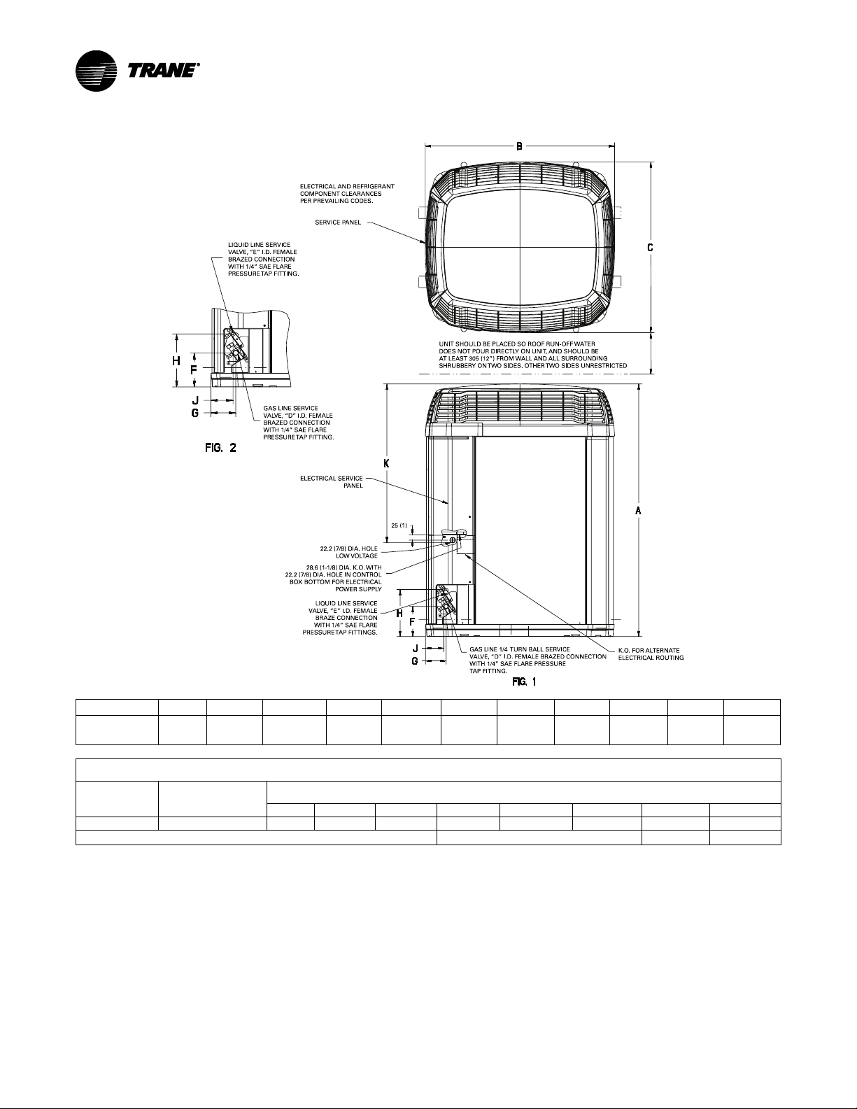
UNIT S HOULD BE PLACED SO ROOF RUN-OFF WATER
DOES NOT POUR DIRECTLY ON UNIT, AND SHOULD BE
AT LEAST 305 (12”) FRO M WALL AND ALL SURROUNDING
SHRUBBERY ON TWO SIDES. OTHER TWO SIDES UNRESTRICTED
SERVICE PANEL
ELECTRICAL AND REFRIGERANT
COMPONENT CLEARANCES
PER PREVAILING CODES.
LIQUID LINE S ERVICE
VALVE, “E” I.D. FEM ALE
BRAZED CONN ECTION
WITH 1/4” SAE FLARE
PRESSURE TAP FITTING.
GAS LINE SERVICE
VALVE, “D” I.D. FEM ALE
BRAZED CONN ECTION
WITH 1/4” SAE FLARE
PRESSURE TAP FITTING.
ELECTRICAL SERVICE
PANEL
22.2 (7/8) D IA. HOLE
LOW VOLTAGE
28.6 (1 -1/8) DIA. K.O. WITH
22.2 (7/8) D IA. HOLE IN CONTROL
BOX BOTTOM FO R ELECTRICAL
POWER S UPPLY
LIQUID LINE S ERVICE
VALVE, “E” I.D. FEM ALE
BRAZE CONN ECTION
WITH 1/4” SAE FLARE
PRESSURE TAP FITTINGS .
25 (1)
K.O. FOR ALTERNATE
ELECTRICAL ROUTING
GAS LINE 1/4 TURN BALL SERVICE
VALVE, “D” I.D. FEM ALE BRAZED CONNECTION
WITH 1/4” S AE FLARE PRESSURE
TAP FITTING.
Model Base A B C D E F G H J K
4TTX6036J 4
1165
(45–7/8)
946
(37–1/4)
870
(34–1/4)
3/4 3/8
152
(6)
98
(3–7/8)
219
(8–5/8)86(3–3/8)
730
(28–3/4)
Model
4TTX6036J 69 78 70 68 67 64 59 56 51
Note: Rated in accordance with AHRI Standard 270–2008
2
A-Weighted Sound
Power Level [dB(A)]
63 Hz* 125 Hz 250 Hz 500 Hz 1000 Hz 2000 Hz 4000 Hz 8000 Hz
SOUND POWER LEVEL
Full Octave Sound Power [dB]
*For Reference Only
4TTX6036J-SUB-1A-EN
Page 3

Product Specifications
OUTDOOR UNIT
POWER CONNS. — V/PH/HZ
(a) (b)
4TTX6036J1000A
(c)
208/230/1/60
MIN. BRCH. CIR. AMPACITY 18
BR. CIR. PROT. RTG. — MAX. (AMPS)
COMPRESSOR
CLIMATAUFF®- SCROLL
30
NO. USED — NO. STAGES 1 — 1
VOLTS/PH/HZ 208/230/1/60
R.L. AMPS
(d)
— L.R. AMPS
13.6 — 79
FACTORY INSTALLED
START COMPONENTS
(e)
INSULATION/SOUND BLANKET
NO (Uses BAYKSKT263)
NO
COMPRESSOR HEAT NO
OUTDOOR FAN PROPELLER
DIA. (IN.) — NO. USED
27.5 — 1
TYPE DRIVE — NO. SPEEDS DIRECT — 1
CFM @ 0.0 IN. W.G.
NO. MOTORS — HP
(f)
4300
1 — 1/8
MOTOR SPEED R.P.M. 850
VOLTS/PH/HZ 200/230/1/60
F.L. AMPS 0.64
OUTDOOR COIL — TYPE SPINE FIN™
ROWS — F.P.I. 1 — 24
FACE AREA (SQ. FT.)
TUBE SIZE (IN.)
24.93
3/8
REFRIGERANT
LBS. — R-410A (O.D. UNIT)
(g)
7 LBS., 11 OZ
FACTORY SUPPLIED YES
LINE SIZE — IN. O.D. GAS
LINE SIZE — IN. O.D. LIQ.
(h) (i)
7/8
3/8
CHARGING SPECIFICATIONS
SUBCOOLING 8°F
DIMENSIONS H X W X D
CRATED (IN.)
47.7 x 35.1 x 38.7
WEIGHT
SHIPPING (LBS.)
NET (LBS.)
255
221
(a)
Certified in accordance with the Air-Source Unitary Air-conditioner
Equipment certification program, which is based on AHRI standard
210/240.
(b)
Rated in accordance with AHRI standard 270.
(c)
Calculated in accordance with Natl. Elec. Codes. Use only HACR
circuit breakers or fuses.
(d)
This value shown for compressor RLA on the unit nameplate and on
this specification sheet is used to compute minimum branch circuit
ampacity and max. fuse size. The value shown is the branch circuit
selection current.
(e)
No means no start components. Yes means quick start kit
components. PTC means positive temperature coefficient starter.
Optional kit shown.
(f)
Standard Air — Dry Coil — Outdoor
(g)
This value approximate. For more precise value see unit nameplate.
(h)
Max. linear length 60 ft.; Max. lift — Suction 60 ft.; Max. lift — Liquid
60 ft. For greater length consult refrigerant piping software Pub. No.
32–3312–0* (* denotes latest revision).
(i)
Trane outdoor condensing units are factory charged with the system
charge required for the outdoor condensing unit and 15 feet of tested
connecting lines. If connecting line length exceeds 15 feet, then final
refrigerant charge adjustment is necessary. Each additional foot over
15 feet requires 0.6 lbs of refrigerant. See the Installer’s Guide for full
charging instructions.
4TTX6036J-SUB-1A-EN
3
Page 4

Mechanical Specification Options
GGeenneerraall
The Outdoor Units are fully charged from the factory
for up to 15 feet of piping. This unit is designed to
operate at outdoor ambient temperatures as high as
115°F. Cooling capacities are matched with a wide
selection of air handlers and furnace coils that are AHRI
certified. The unit is certified to UL 1995. Exterior is
designed for outdoor application.
CCaassiinngg
Unit casing is constructed of heavy gauge, galvanized
steel and painted with a weather-resistant powder paint
finish on all louvered panels and the fan top panel. The
corner panels are prepainted. All panels are subjected
to our 1,000 hour salt spray test . The base is made of a
CMBP-G30 weatherproof material to resist corrosion.
RReeffrriiggeerraanntt CCoonnttrroollss
Refrigeration system controls include condenser fan,
compressor contactor and high pressure switch. High
and low pressure controls are inherent to the
compressor. A factory supplied liquid line drier is
standard. Some models may require field installation.
CCoommpprreessssoorr
The compressor features internal over temperature,
pressure protection and total dipped hermetic motor.
Other features include: Centrifugal oil pump and low
vibration and noise.
CCoonnddeennsseerr CCooiill
The outdoor coil provides low airflow resistance and
efficient heat transfer. The coil is protected on all four
sides by louvered panels.
LLooww AAmmbbiieenntt CCoooolliinngg
As manufactured, this system has a cooling capacity to
55°F. The addition of an evaporator defrost control
permits operation to 40°F. The addition of an
evaporator defrost control with TXV permits low
ambient cooling to 30°F.
TThheerrmmoossttaattss—Cooling only and heat/cooling (manual
and automatic change over). Sub-base to match
thermostat and locking thermostat cover.
EEvvaappoorraattoorr DDeeffrroosstt CCoonnttrrooll — See Low Ambient
Cooling.
Trane optimizes the performance of homes and buildings around the world. A business of Ingersoll Rand, the leader in
creating and sustaining safe, comfortable and energy efficient environments, Trane offers a broad portfolio of advanced
controls and HVAC systems, comprehensive building services, and parts. For more information, visit www.Trane.com.
Trane has a policy of continuous product and product data improvements and reserves the right to change design and specifications without notice.
©2015 Trane
4TTX6036J-SUB-1A-EN
Supersedes (New)
01 Oct 2015
 Loading...