

QUICK-START
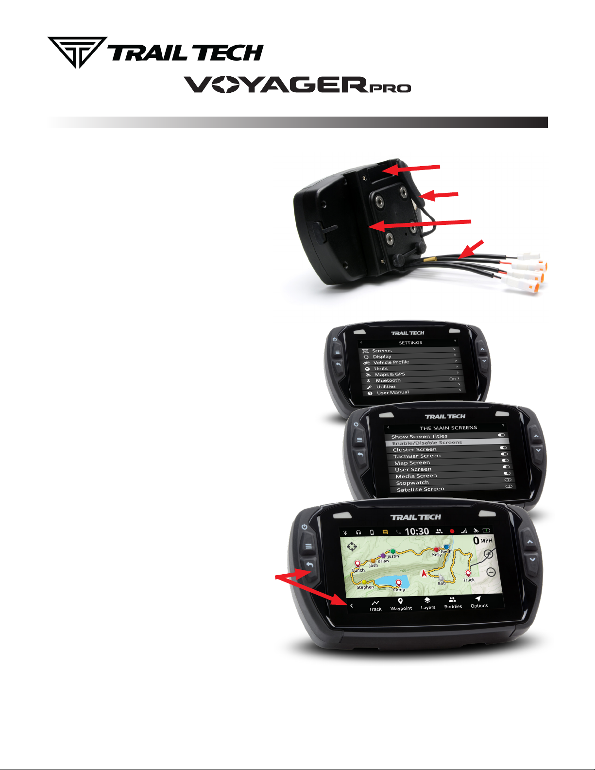
1. MOUNTING THE DOCK:
Voyager Pro’s dock is made to be bolted to the vehicle.
Use the mounting hardware included in your kit, or use any
AMPs style mount from the popular RAM Mounts manufacturer.
Voyager Pro quickly snaps in and out of the dock for quick
removal when not in use, and can be locked to the dock using a
tiny allen wrench in the side of the dock.
Tech Support: (844) 378-8143
010-ELV-192
technicalservice@apexproductgroup.com
Press Button to Release
Voyager Pro From Dock
Rubber Pin Protector
Allen Lock
2. VEHICLE SENSORS:
You should install the wheel sensor, ignition sensor, engine
temperature sensor, and vehicle power connection. If you plan
not to use one of these sensors, some abilities of Voyager Pro
may not function.
3. DC POWER:
DC power required. Do not connect Voyager Pro to AC power
except when using the AC wall charger. Connect to a switched 12V
DC power source so that power to Voyager Pro is cut when the
vehicle is turned off. When connected to the vehicle battery, charging
will begin immediately and Voyager Pro should have full functionality.
On some bikes, erratic tach readings can be fixed by wiring the
power directly to the battery instead of behind the key switch.
There are few menu options to change when Voyager Pro is used
without a connection to vehicle power:
1. Vehicle Profile > Wake Detection, Speed Source, Charge Mode
2. Maps and GPS Setup > AutoLog Source
4. USER MANUAL:
The user manual is embedded in Voyager Pro itself. Access it by
pressing the Menu button and looking for “User’s Guide” at the
bottom of the main menu. The manual is available online at
trailtech.net.
Sensor Wires
5. MAIN SCREENS:
Voyager Pro has several main screens.
Press UP and DOWN on the buttons to move
between screens. Press the menu button to
open the main menu. On some screens like
the map screen, press the back button to open
a sub-menu with screen-specific options.
Press Here on
Map Screen to
Open Mini-Menu
6. ENABLE SCREENS:
Voyager Pro has a series of main information screens. Screens
can be enabled/disabled in the settings menu. By default, the
stop watch and satellite screens are hidden. Available screens
include: the gauge cluster screen with a large speedometer, the
tach screen with an animated tach graph, the map screen, the user
definable screen, the stop watch screen, and the GPS satellites
screen.
QUICK-START
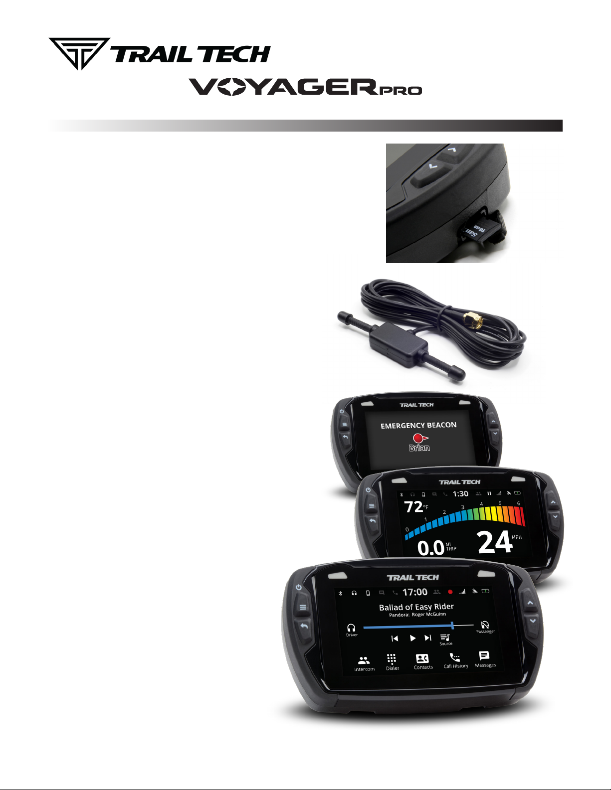
7. MICROSD CARD SLOT:
A MicroSD card (not included in kits) enables transfer of tracks between Voyager Pro and a
PC. During operation, make sure the card slot cover is properly seated to keep debris out.
Tracks saved as GPX files on your computer can be placed on the MicroSD memory card,
then imported onto Voyager Pro for viewing and route following. This is a great way to share
recorded tracks, or for pre-planning trips. Music files saved on the MicroSD card can be
played from the Media screen.
Use exFAT type if you format your MicroSD card on a PC.
8. GPX FILES:
In the map screen’s mini menu you can record, load, and save GPX files.
GPX files are custom made tracks and riding areas that you can follow
yourself, or create and share with the community. GPX is an open standard,
so there are a variety of tools availble to work with GPX files.
9. BUDDY TRACKING:
Buddy Tracking connects multiple Voyager Pros to a private location
tracking network. Once connected to the buddy tracking group, you will see
map markers showing the name and location of all group members. The
technology supports up to 20 riders in a single group.
The mesh network capability increases the comfortable following distance
between you and your buddies. The typical antenna range between buddies
is .5 to 1.5 miles, increasing with line of sight and fewer obstructions.
Tap the centering icon in the top left of the map screen to toggle “Buddy
Mode” where the map will always keep buddies on-screen.
Select a “Destination Buddy” to draw a line on the map between you and
your buddy to easily keep track of them.
The external V2V antenna is required to use buddy tracking features.
MicroSD
Card Slot
V2V Antenna
Required for
Buddy Tracking
11. EMERGENCY BEACON:
When you activate the emergency beacon, your map marker flashes red on
everyone elses screens. It is not a rescue beacon, the national guard will NOT be
notified.
12. BLUETOOTH:
Voyager Pro contains two Bluetooth chips that can control
two streams each. Connect up to two phones and two
headsets or speakers. The headsets can function as an
intercom between riders, or as a loudspeaker. Route songs
from your phone through Voyager Pro to headset or speaker.
13. WARNING INDICATORS:
First set a threshold for max tach and temperature. Whenever
Voyager Pro detects the vehicle is exceeding the limit, the
indicator lights will alert you of the situation. Tach warnings
flash, temperature warnings are solid. Set it up under vehicle
profile in the main menu.

POWER AND TACH SENSORS
INSTALLS
POWER CONNECTION:
FOR USE ON 12V DC SYSTEMS ONLY!
Use a volt meter to confirm nominal 12V DC.
Connecting to AC power will damage Voyager Pro and void the warranty.
Vehicles with DC Power: Voyager Pro requires DC power. Vehicles with a battery or
capacitor and regulator/rectifier produce DC power. Connect the power wire directly to the
vehicle’s 12V battery. Connect the red wire to the positive(+) battery terminal and the black
wire to the negative(-) battery terminal.
Vehicles with AC Power: Use the Voyager Pro AC wall charger, or upgrade to a
DC electrical system. Most carburated MX bikes put out AC power, but Voyager Pro
requires DC power.
Fuse: Introducing a fuse into the circuit before electronics is always a good idea. Use a 2 amp fuse with Voyager Pro (not provided.)
Power Wire
SENSORS:
The Voyager Pro vehicle sensors
fasten securely to the dock using
waterproof JST connectors.
The connectors are all different shapes
(you cannot plug a sensor into the
wrong connector.)
Engine Temperature Sensor
Power Wire
Voyager Pro
Vehicle Dock
V2V Antenna
GPS Antenna
Ambient Temperature Sensor
Wheel Sensor
Tach Ignition Sensor
TACH IGNITION SENSOR:
The ignition sensor enables tachometer readings and the
animated bar graph on the tach screen of Voyager Pro.
Coil
OPTION 1: (Preferred option for most vehicles.)
Capacitive coupling to spark plug wire:
1.
To install ignition sensor wire, wrap the
red part of the sensor wire around the
spark plug wire 5 times.
If required, you may shorten the length of the ignition
sensor. Be very careful when stripping back the black
casing to avoid damaging the inner red wire.
OPTION 2:
If the coil is attached to the spark plug, then wrap the sensor like this:
Step 1:
Pull water-seal
down. Wrap
ignition sensor
around spark
plug.
Water
Seal
Step 2:
Replace
water-seal.
Spark Plug
Ignition
Sensor
Wrap
Ignition
Sensor
Step 3:
Reinstall
spark plug
into motor.

TEMPERATURE SENSORS AND ANTENNAS
INSTALLS
TEMPERATURE SENSORS:
Most Voyager Pro kits contain a model-specific temperature sensor. Installing the temperature sensor
enables temperature readouts on Voyager Pro’s gauge screens. Alternative sensors are available.
Vehicles cooled with water use sensors to measure the fluid temperature, while air-cooled machines take
the cylinder head’s temperature at the spark plug. The radiator fin sensor is the easiest installation.
Radiator Hose
Sensor Installation:
1.
Drain uid.
2.
Measure inner diameter
Tighten
Mark
& Cut
CVT Sensor Install:
(Continuously Variable Transmission)
200ºF+ Warning: CVT Belt wear occurs
more rapidly at high temperatures.
Let the belt cool down to increase lifespan.
Drill 13/64” (5mm) hole in
1.
hard plastic CVT exhaust.
Thread sensor into hole.
2.
The sensor threads are M6x10.
Use high temp RTV (silicone
3.
gasket sealer) to seal case cover.
Not included in kit.
of hose before cutting.
3.
Mark hose.
4.
Cut hose.
5.
Slide on hose clamps.
6.
Install sensor & tighten
hose clamps.
Sensor replaces
crush washer
Radiator Fin
Sensor Installation:
Conrm correct size.
1.
Apply thermal grease to
2.
maximize heat transfer.
Carefully press sensor
3.
between radiator ns.
If the in sensor is too large,
le it to size rather than
forcing it into the radiator.
CHT Cylinder Head
Spark Plug
Sensor Installation:
Remove crush
1.
washer from
spark plug.
Replace with
2.
temperature
sensor.
Re-install
3.
spark plug.
Screw
Sensor Installation:
1.
2.
V2V AND GPS ANTENNAS:
V2V Antenna:
The vehicle-to-vehicle antenna
sends radio signals between your
vehicle and other vehicles with
Voyager Pro. It works well and is
included in most Voyager Pro kits.
The plastic V2V antenna is
designed to be mounted to a
non-metallic surface like a number
plate or shroud, with the ears aimed
vertically, up and down. Higher
up on the vehicle is better, as the
engine and metal panels can block
reception.
V2V Antenna
Required for
Buddy Tracking
GPS Antenna
GPS Antenna:
The internal GPS antenna is
adequate for normal use. If
there is excessive metal around
the Voyager Pro mounting
location, the reception may be
affected.
An external GPS antenna can
be installed into the dock’s
GPS anternna port to achieve
a better antenna mounting
position. The external GPS
antenna available from Trail
Tech should be mounted flat,
on a non-metallic surface.

WHEEL SENSORS
INSTALLS
KTM WHEEL SENSOR
Trail Tech wheel
sensors work with the
KTM and Husqvarna
OEM install location.
Screw the wheel
sensor into the OEM
caliper position. Insert
the black magnet into
the pre-drilled hole in
the rotor and secure
with the retainer clip.
KTM Magnetic
Retainer
KTM OEM Wheel
Sensor Position
FORK GUARD WHEEL SENSOR
If there are fork
guards next to the
brake rotor, then the
fork guard wheel
sensor can be
installed as shown.
Try to have the tip of
the sensor about 1/2
inch away from the
magnet in the rotor.
Rotor Bolt Magnet Fork Guard
Wheel Sensor
INVERTED FORK WHEEL SENSOR
If the fork is close to
the brake rotor, then
the VHB fork sensor
can be used. Peel
and stick the sensor
to the fork.
Try to have the tip of
the sensor about 1/2
inch away from the
magnet in the rotor.
Rotor Bolt Magnet Inverted Fork
VHB Wheel Sensor
ROTOR SHIELD WHEEL SENSOR
For UTVs and quads
with a rotor shield,
position the sensor
there.
Drill a 3/8” hole and
use the jam nuts to
secure the sensor to
the rotor shield. Use
loctite rather than
over-tightening the
jam nuts.
Rotor Shield
Wheel Sensor
BRAKE CALIPER WHEEL SENSOR
Some ATVs require
mounting the wheel
sensor directly to the
brake caliper.
Drill a 1/8” hole
through the caliper
mount, then use the
self-tapping screw to
secure the sensor.
Brake Caliper
Wheel Sensor
MAGNET INSTALLATION:
Install a magnet on the brake rotor to trigger
the speed sensor each wheel rotation.
Remove one of the stock rotor bolts and
install the magnetic rotor bolt as shown, do
not overtighten past 10 ft-lb of torque. If the
magnetic bolt will not work, the kit includes a
spare magnet that can be installed into one
of the rotor spaces. Use the included retainer
clip or epoxy such as JB Weld to secure.
C-BRACKET WHEEL SENSOR
Some kits include
a metal C-bracket
to help mount the
sensor, as shown.
Use the jam nuts to
secure the sensor to
the C-bracket. Use
loctite rather than
over-tightening the
jam nuts.
Magnetic Retainer or Spare MagnetMagnetic Rotor Bolt
C-Bracket
Wheel Sensor

WHEEL SENSORS
SETUP
WHEEL SENSOR TEST:
Test for correct sensor/magnet placement before permanently mounting.
1. Set the vehicle on a stand so that the front (left) wheel spins easily.
2. Plug the wheel sensor cable into the computer.
3. Install the magnetic bolt.
4. Hold the sensor in place on the caliper mount by hand. While someone
watches the computer, roll the wheel. If the computer does not register,
move the magnet or sensor and try again. There should be 1/2” or less
gap between the sensor and magnet.
Do not mount so that the magnet passes the middle section of the
sensor. Either the sensor will not register at all; or the sensor will
register twice, causing a “double trigger” effect (computer displays
twice the true speed.) If a double-trigger is unavoidable, divide the wheel
size setting in the computer by 2 to correct the problem.
MEASURE WHEEL SIZE:
Knowing your exact wheel size it critical for the wheel sensor to calculate
correct speed and distance data.
Magnet Rotation Path
When comparing calibration to GPS data, use a long straight section of road
with no tight corners or small vertical movements.
Method 1: Ruler
Find the circumference of front wheel by measuring its diameter in millimeters.
Multiply the Wheel Diameter by 3.14. The result is your wheel size.
Method 2: Rolling
On a at surface, mark the tire sidewall and the ground with a marking pen. Roll the
wheel until the mark on the tire completes one revolution and is back on the ground. Mark
the ground at this location. Measure the distance between the marks on the ground in
millimeters (multiply inches by 25.4 to convert to mm). Use this number for your wheel size.
For accuracy, the rider’s weight should be on the bike when making the measurement.
Method 3: Distance Measurement
This is the most accurate method.
1. Set the wheel size to 2110mm (motorcycle) or 1675 (ATV).
2. Find a length of road where the distance is known.
3. Ride the distance, noting how far the computer reads (i.e. the road
is known to be 5 miles and the computer shows 4.95 miles.)
4. Use the numbers to solve for X in the following equation:
(new wheel size)
5 x 2110
X =
4.95
(actual miles) x (current wheel size)
=
X =
(current miles)
10550
4.95
X = 2131
Wheel Size =
Wheel Diameter(mm)
x3.14
Diameter
Generic/Average Sizes:
Motorcycle:
ATV:
2110 mm
1675 mm
Wheel Size:
Enter the number you calculate from one of
the above formulas into setup mode.
x3.14
 Loading...