

DC CONVERSION
CRF 250/450R DC CONVERSION
INSTALL ELECTRICAL SYSTEM:
010-ELV-59
S-8200
Tech Support: 360-687-4530
tech_support@trailtech.net
All wires are connector and color matched. An experienced technician can complete this installation
Remove seat to expose the air box.
1:
2:
Remove gas tank.
3:
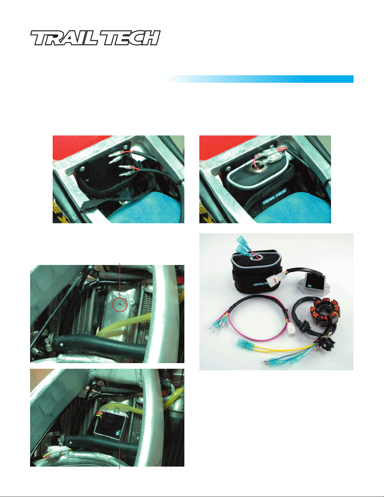
Using a 13/64” (5.15mm) drill bit, mark and drill two holes lining up the Trail Tech battery mounting plate to the bike frame. After
the holes are drilled, use the two included M6 self-tapping screws to mount the mounting plate to the bike frame (Fig.1.)
4:
Install the battery bag to the mounting plate, as shown below. Pull the strap tightly to securely hold the battery (Fig.2.)
Fig.1
Use a 13/64” (5.15mm) drill bit to drill a hole
5:
frame (Fig.3.) Use the included M6 self-tapping screw to
mount the regulator/rectifier (Fig.4.)
HOLE FOR THE REGULATOR/RECTIFIER IS LOW ENOUGH
TO ALLOW THE GAS TANK TO BE RE-INSTALLED.
without instructions by matching connectors and wire colors.
Fig.2
* in the bike
*MAKE SURE THE
Fig.5
Fig.3
Fig.4
MOUNT REGULATOR/RECTIFIER AS LOW AS POSSIBLE.
Install Trail Tech stator (See reverse side of instructions.)
6:
7:
Install the wiring harness
Plug the wire harness white 4-pin connector into the
A:
mating connector on the regulator/rectifier. (Fig.4.)
B:
Connect the yellow wires from the wire harness to the
yellow wires from the stator.
C:
Connect the red and black wires from the wire harness to
the red and black wires from battery. (Fig.1 and Fig.2.)
D:
Connect the remaining stator wires to the stock wires
that the stock stator was disconnected from.
To wire in a headlight or other electrical accessory, connect
8:
the light’s red and black wires to the battery. Add a switch
between the light and battery. The light will never shut off if
it is wired directly to the battery with no switch (drains the
battery.)
:
DC CONVERSION
CRF 250/450R DC CONVERSION
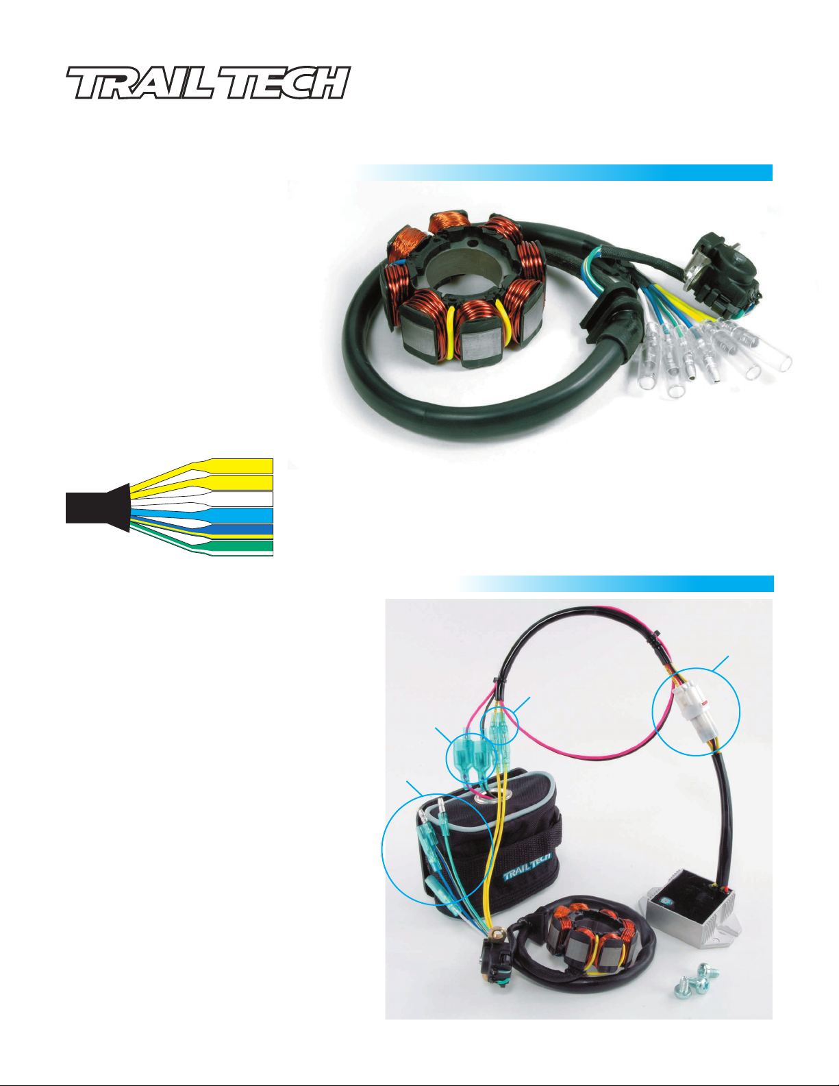
INSTALL TRAIL TECH STATOR:
Drain a small amount of oil out of the crank
1:
case.
2:
Lay the bike on its right side.
3:
Remove the left engine side case.
5:
Remove old stator assembly. Do not damage
hardware: it will be used with the new stator.
6:
Install Trail Tech stator. Route wires so they
will not be pinched. Use thread locking
compound (clean case thoroughly before
using thread locking compound.)
7:
Replace sidecase. Torque bolts to OEM
specifications.
Wire colors are the same for both
•
the stock and Trail Tech stators.
Yellow Wire:
Yellow Wire:
Stator Wire
White Wire:
Light Blue Wire:
Dark Blue w/Yellow:
Green w/White Wire:
Tech Support: 360-687-4530
tech_support@trailtech.net
Lighting lead. Connect to a yellow wire from regulator/rectifier.
Lighting lead. Connect to the other yellow wire from regulator/rectifier.
Ignition lead. Connect to white wire from OEM wire harness.
Ignition lead. Connect to light blue wire from OEM wire harness.
PIP lead. Connect to dark blue w/yellow wire from OEM wire harness.
PIP lead. Connect to green w/white wire from OEM wire harness.
ELECTRIC SYSTEM WIRING QUICK-VIEW:
P-1:
Trail Tech Regulator/Rectifier connected to the
included Trail Tech wiring harness.
The reg/rec converts AC power to DC.
P-2:
Trail Tech stator connected to the included Trail
Tech wiring harness.
The stator produces power and recharges the battery
when the motorcycle is turned on.
Trail Tech battery connected to the included Trail
P-3:
Tech wiring harness.
A battery is required for DC power. The size, power
and performance of Trail Tech batteries is excellent,
but other types of batteries may also be used, such as
lead acid batteries. The CRF 250/450R has limited
space to mount a lead acid battery.
P-4:
Connect these wires to the stock wire harness.
They plug into the same wires the stock stator is
unplugged from. Wire colors are the same as the
stock stator.
P-3
P-4
P-1
P-2
 Loading...