

Page 1
MOTORSPORT COMPUTER
USER’S
MANUAL
A
PRODUCT
Page 2

Page 3

1
Table of Contents
PAGE #
TABLE OF CONTENTS
1
A NOTE TO YOU
2
PRECAUTIONS 3
SPECIFICATIONS
4
PARTS & FEATURES
6
INSTALLATION
10
MEASURE WHEEL SIZE
16
DATA SETTING MODE
18
NORMAL MODE
22
SLEEP MODE
25
ENDURO MODE 26
LAP TIMER MODE
38
TROUBLESHOOTING 46
GLOSSARY OF TERMS
48
Page 4

2
A Note to You
Thanks for Buying a TrailTech
Motorsport Computer:
TrailTech Motorsport Computers bring functionality and life to your
motor vehicle with high quality and innovation. To ensure you enjoy
years of trouble-free operation, this Users Manual contains valuable
information about how to operate and maintain your computer
properly.
Please read this manual carefully.
Please Record Important Information:
Whenever you call to request service for Lynx, you need to know
the date of purchase, dealer’s name, address, and telephone
number.
PURCHASE DATE
DEALER NAME
DEALER ADDRESS
DEALER PHONE
Keep this book and sales slip together for future reference.
Page 5

3
Precautions
WARNING: When
using Lynx, follow basic
precautions, including the
following:
• Read all instructions before
using Lynx.
• Use Lynx only for its intended
function.
• To reduce the risk of injury,
do not disassemble Lynx or its
accessories.
• Lynx can be used in the
rain but should not be used
underwater.
• Do not leave the main unit in
direct sunlight when not riding.
• Check relative positions
and gap between sensor and
magnet periodically.
• Clean the docking station
contacts and the bottom of the
main unit periodically.
• Do not use any type of
lubricant on the docking station
or external computer contacts.
Any material that will attract
dirt or dust will greatly reduce
contact life.
• Avoid contact with gasoline,
degreasers or other chemical
cleaners as they may damage
the computer.
REMEMBER TO PAY ATTENTION
TO THE TRAIL WHILE RIDING.
Page 6
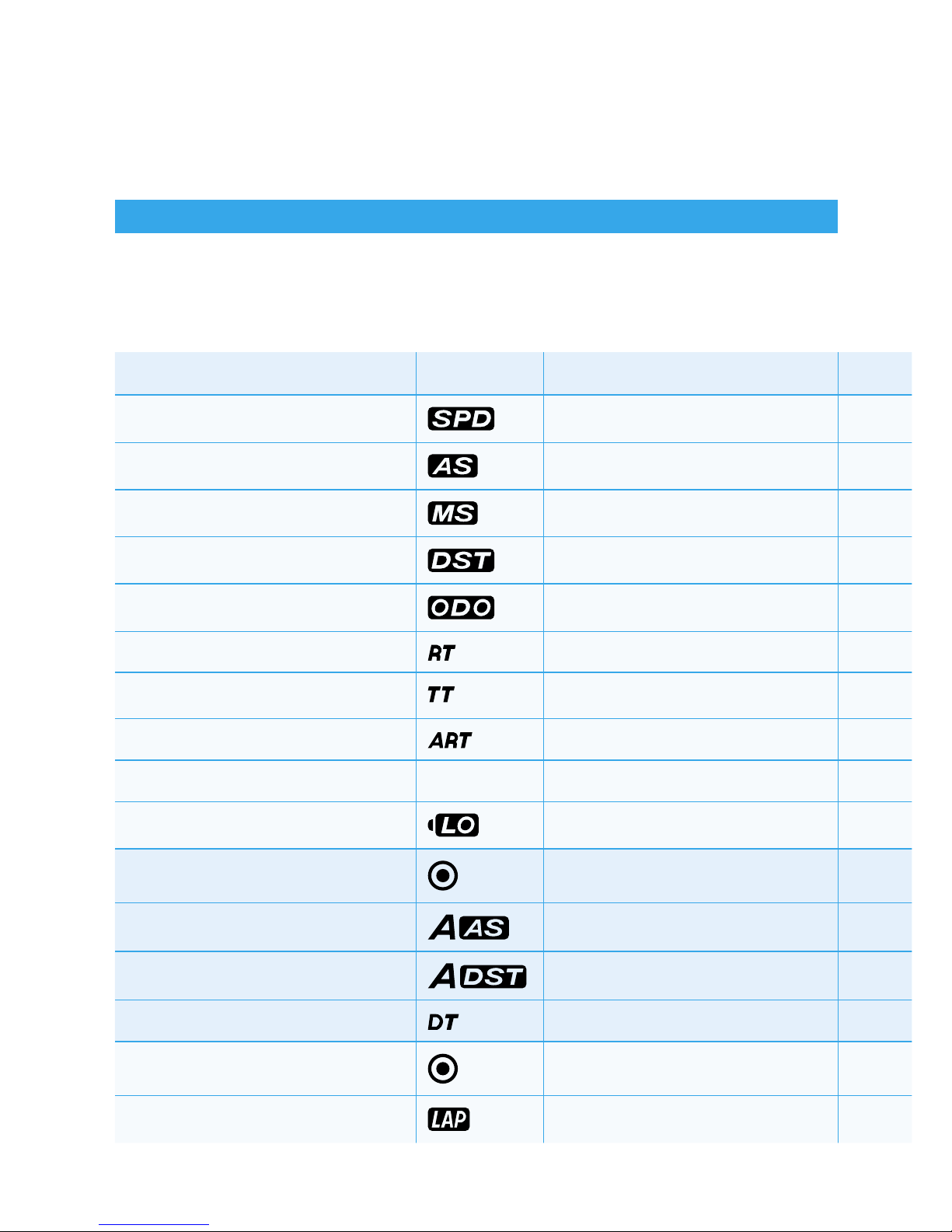
Specifications
4
FUNCTION DISPLAY RANGE UNITS INCREMENTS ACCURACY
CURRENT SPEED
0399.9 KM/H or M/H KM/H or M/H 0.1 KM/H or M/H +/- 0.1%
AVERAGE SPEED
0399.9 KM /H or M/H KM/H or M/H 0.1 KM/H or M/H +/- 0.1%
MAXIMUM SPEED 0399.9 KM/H or M/H KM/H or M/H 0.1 KM/H or M/H +/- 0.1%
DISTANCE
0.0-9999.9 KM or M KM/H or M/H 0.1 KM/H or M/H +/- 0.1%
ODOMETER 0-99999 KM or M KM/H or M/H 0.1 & 1 KM/H or M/H +/- 0.1%
RIDING TIME
999 hours 59 minutes Hours:Minutes 1 Minute +/- 0.1%
STOP WATCH
999 hour 59 min 59 sec H:M:S 1 Second +/- 0.1%
ACCUM. RIDE TIME
999 hour 59 min 59 sec Hours:Minutes 1 Minute +/- 0.1%
12H or 24H CLOCK 00:00:00 12:59:59 or 23:59:59 H:M:S 1 Second +/- 0.1%
LOW BATTERY
About 1 Year Battery Life 2.5V +/- 0.1V
ENDURO MODE
ADJUSTED AVG. SPEED 999.9 KM/H or M/H KM/H or M/H 0.1 KM/H or M/H +/- 0.1%
ADJUSTED DISTANCE
0.0-9999.9 KM or M KM/H or M/H 0.1 KM/H or M/H +/- 0.1%
DELTA TIMER
+/- 99:59:59 H:M:S 1 Second +/- 0.1%
LAP TIMER MODE
LAP COUNTER 19 Laps Laps 1 Lap
Page 7

Specifications
SENSOR:
COMPUTER DIMENSIONS:
COMPUTER WEIGHT:
WHEEL CIRCUMFERENCE:
OPERATION TEMP:
STORAGE TEMP:
No Contact Magnetic Sensor
4.13” x 2.36” x 1.77”
100 grams (0.22 pounds)
0 to 3999 mm (1 mm Increments)
0ºC to 60ºC (32ºF to 140ºF)
-20ºC to 80ºC (-4ºF to 176ºF)
5
Page 8
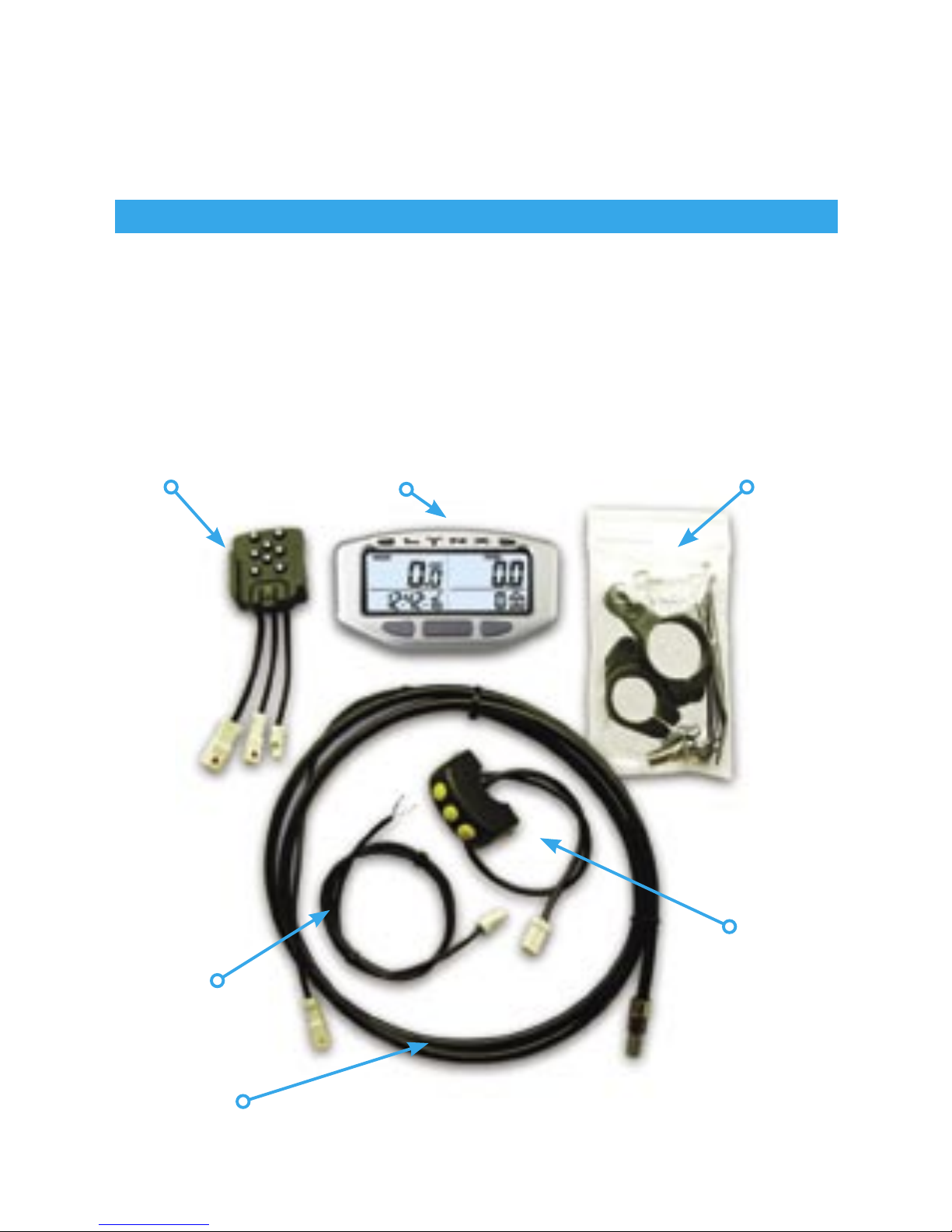
Parts & Features
Lynx Computer Kit:
The Lynx Computer Kit comes packaged with several accessories
for quick and easy installation. Please refer to the installation
guidesheet for tips on installing to specific machines.
6
Docking Station Main Computer Body Installation Pack
Optional
Remote
Power Cable
Sensor Cable
Page 9
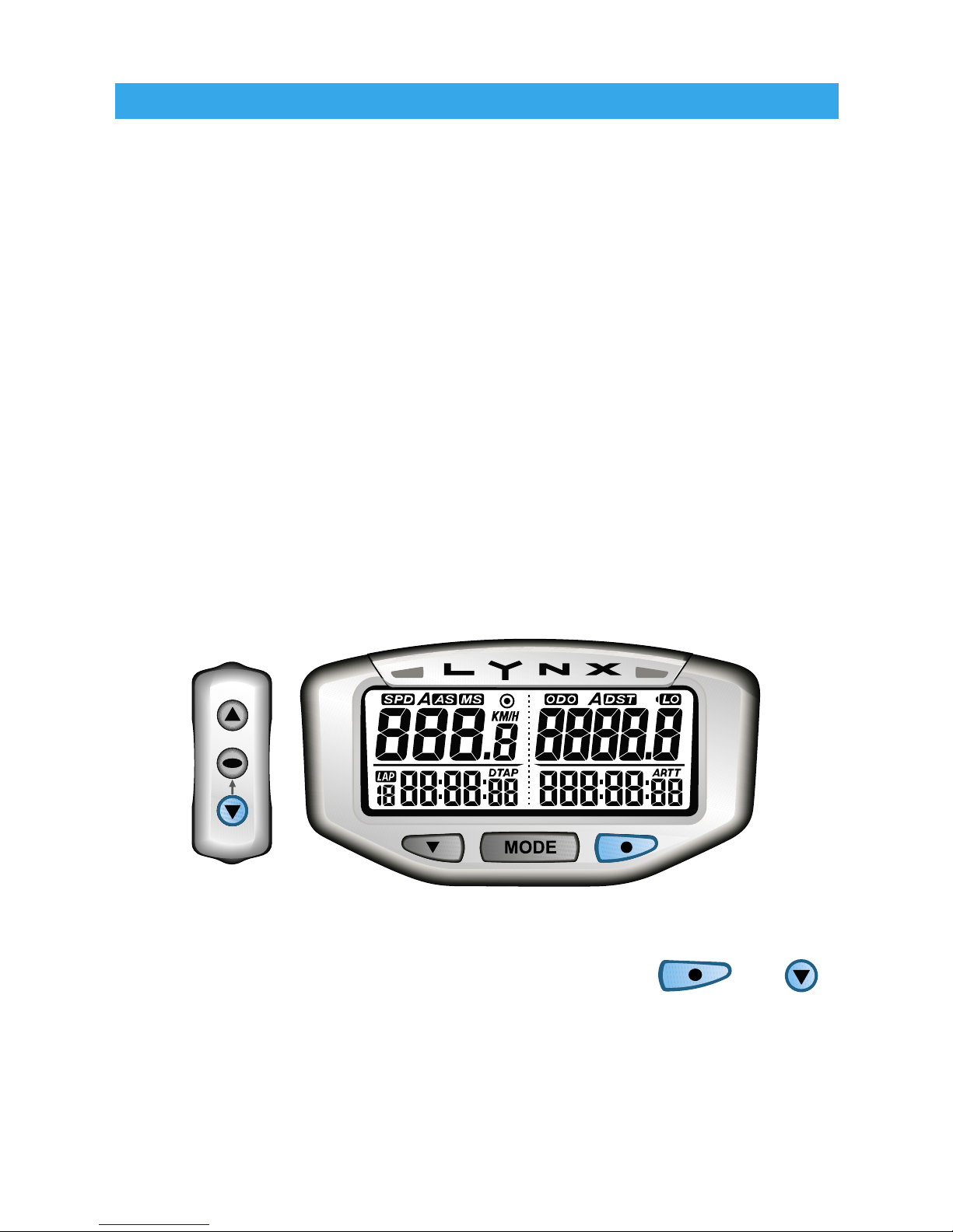
Backlight:
Lynx is equipped with a backlight for easy viewing during night-time
operation.
• When connected to the vehicle’s power vsystem, Lynx will light up
with all five LED’s. If running off its own internal battery, Lynx will
light up with one LED.
• When connected to the vehicle’s 12 volt system, Lynx will remain
lit as long as it senses wheel movement. After 5 minutes of inactivity Lynx shuts off the backlight. Press any button or move the
wheels and Lynx will light up again.
• If Lynx is running off its own internal battery, it will only stay lit for
3 seconds.
TO ACTIVATE BACKLIGHT MANUALLY, PRESS OR .
Parts & Features
7
Page 10
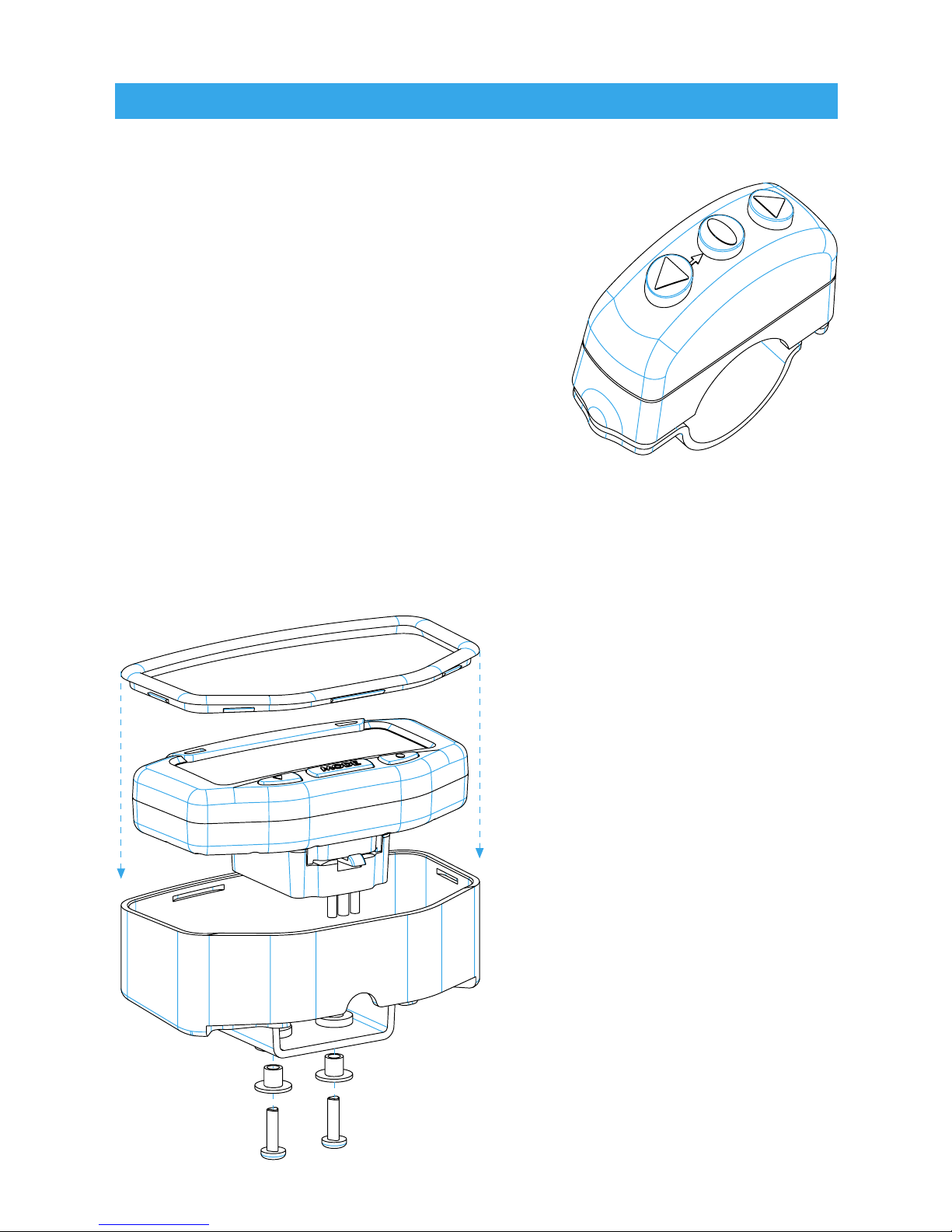
Optional Remote:
Lynx has an optional handlebar
mounted remote. It allows the rider to
easily access computer functions while
riding. The remote also allows Lynx to
access its advanced functions: Enduro
& Lap Timer Modes*.
*Lynx does not require the optional
remote to perform Normal Mode
functions.
Please contact your local TrailTech dealer for more information on
the optional Lynx Remote Switch or visit www.TrailTech.net.
Optional
Dashboard:
Lynx has an optional
aluminum billet guard
dashboard.
• Places computer in optimal
viewing position.
• Provides protection in harsh
riding conditions.
Please contact your local
TrailTech dealer for more
information on the optional
Lynx Dashboard or visit www.
TrailTech.net.
Parts & Features
8
Page 11
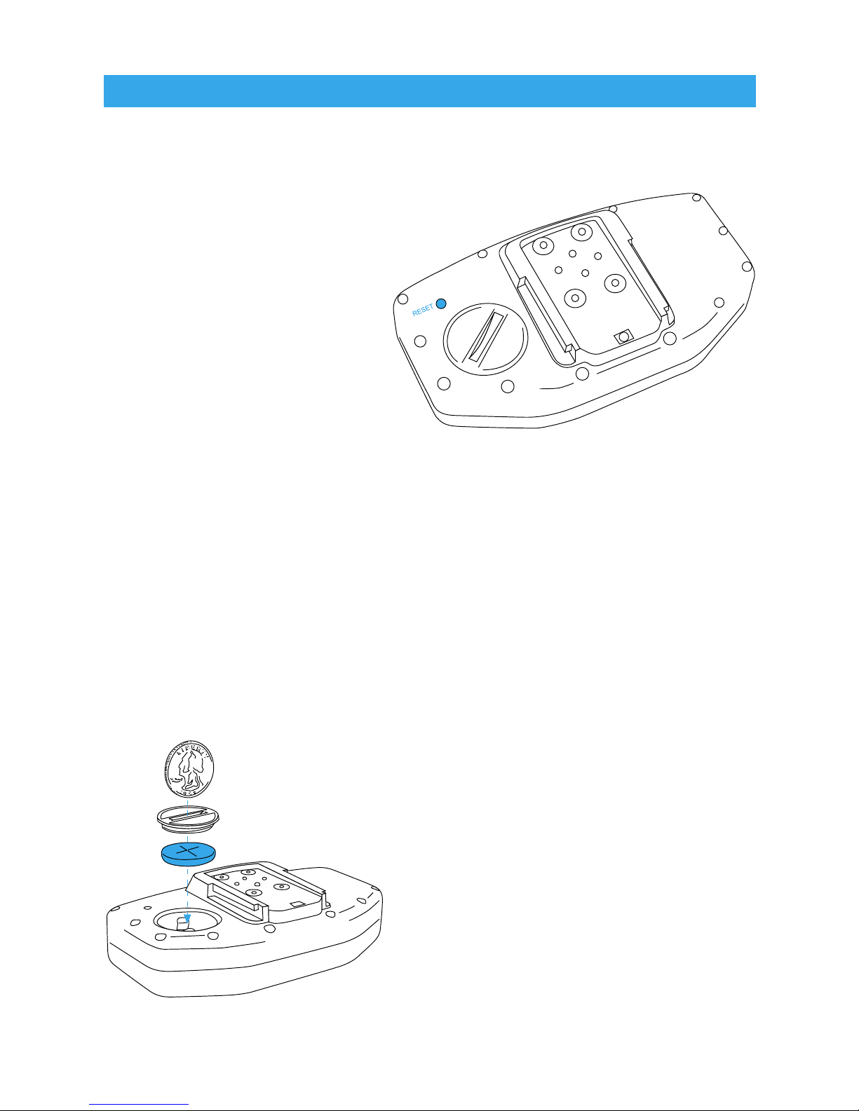
Reset Button:
Use of the Reset Button
will erase all saved
data and settings
except Odometer and
Accumulated Ride Time.
The reset button is
intended to reset Lynx if
the screen freezes up.
Press it once and the
screen will restore itself.
User settings will need to
be re-entered.
Internal Battery:
Your Lynx computer has an internal 3.0V watch type battery
(#CR2032). Under normal use, this battery will last approximately
one year. The computer and its optional remote switch can both be
run from this battery alone. To conserve battery power, the back-
light will stay lit for only 3 seconds
before shutting off automatically.
To change the battery, unscrew
the battery cap on the back of
the computer. Make sure the
positive side of the battery is facing up when replaced.
REPLACE WITH BATTERY
MODEL NUMBER #CR2032
Parts & Features
9
Page 12
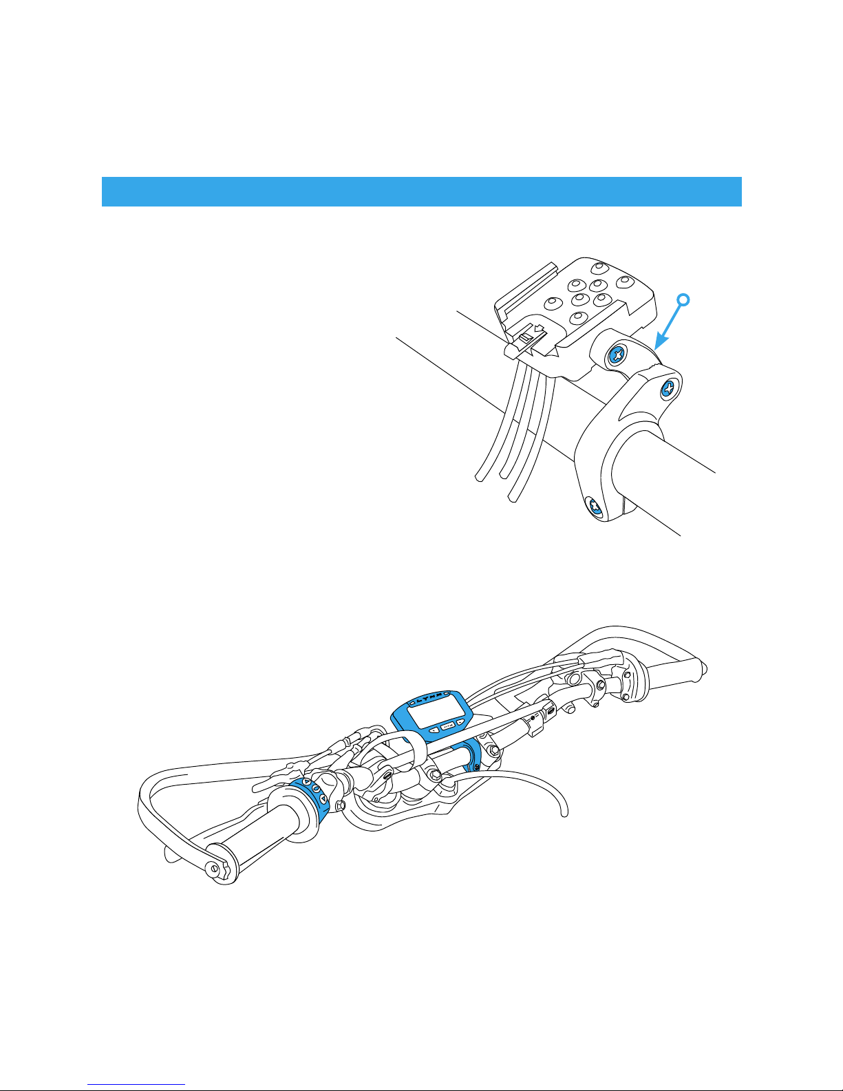
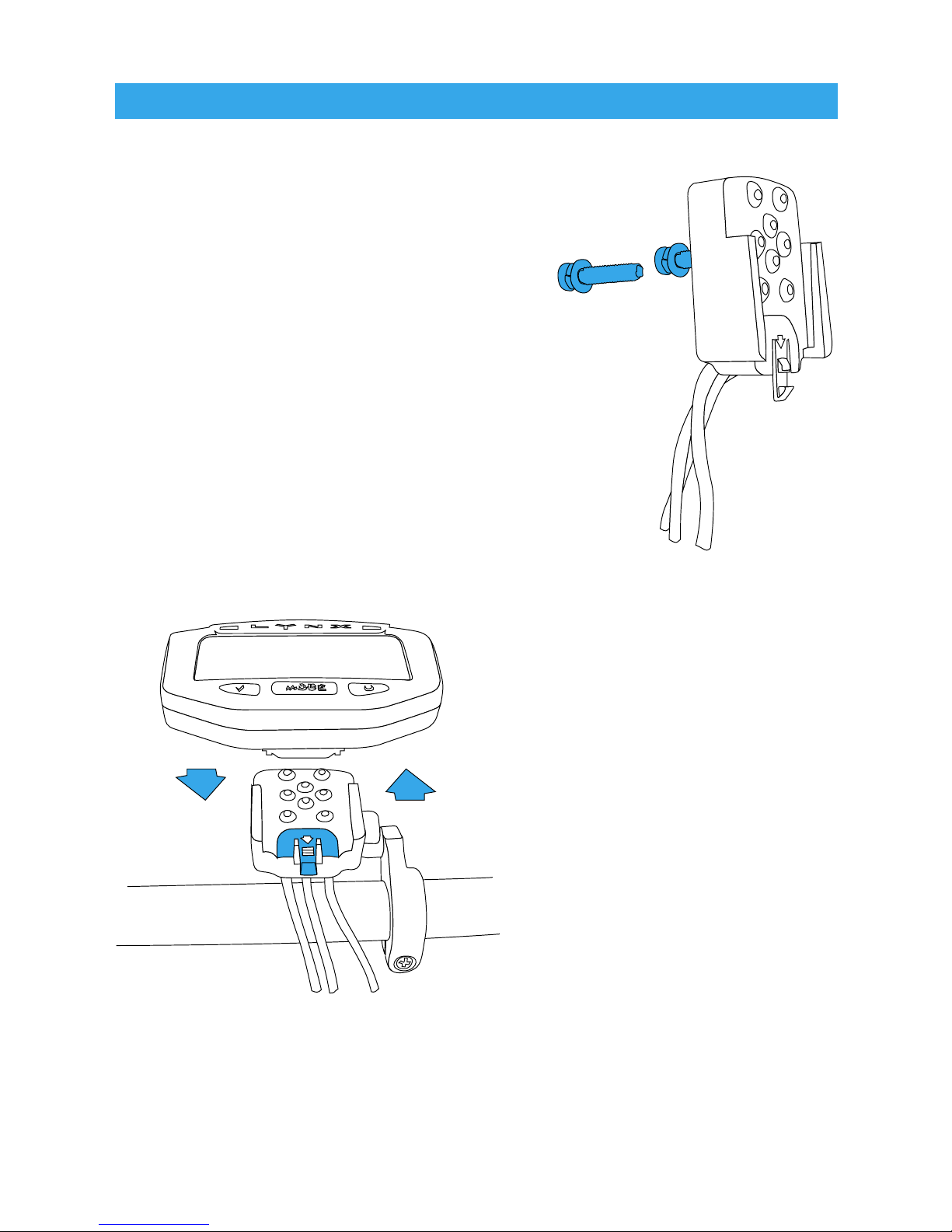
Method 1)
Bar Mount:
Place bolts as shown in
picture.
Remember to use provided
nuts when placing bolts.
Use the provided strip of black
rubber to provide the clamp with a
non-slip surface.
Tip: Remove plastic Link Arm for a more stable
install. The Link Arm is not required.
Link
Arm
Typical Motorcycle Installation
Shown with Bar Mounted Computer &
Optional Remote
10
Installation
Page 13
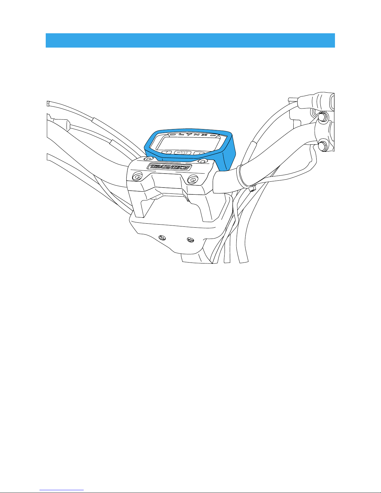
Method 2)
Billet Dashboard Mount
The Optional Billet Aluminum Dashboard will protect Lynx from
impacts and place it in the optimal viewing position.
Mounting varies between vehicle models.
Please contact your local TrailTech dealer for more information on
the optional Billet Dashboard or visit www.TrailTech.net.
Installation
Typical ATV Installation
Shown with TrailTech Billet Dashboard &
TrailTech Medium Bend ATV X-Bar Handlebars
11
Page 14
Method 3)
Flat/Surface Mount:
There are two screw holes on the
back of the docking station (see
picture.) Use the included screws to
mount to any flat surface (e.g. stock
odometer mounting bracket or body
panel.)
Make sure that the cables will not be
chafed or damaged in their mounting
location.
Docking Station:
Lynx easily slides on and off
the docking station. Simply
slide the computer down
until it clicks into place.
To remove Lynx from the
docking station, press the
clip down gently and slide
Lynx up and off.
Installation
12
Page 15
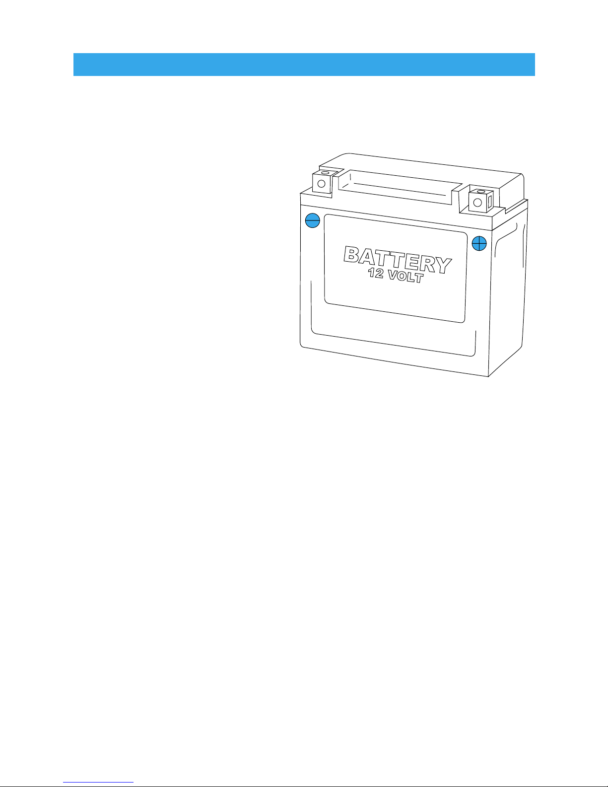
12 Volt Systems:
If possible, install Lynx to a 12 volt system.
The backlight function will
stay lit while riding at 5 times
the brightness over the builtin battery. The pace LED’s
will be activated for Enduro
and Lap Timer Modes.
Lynx is polarity independent.
Either lead can go to the
positive or negative post on
the battery.
OPTION 1)
BATTERY WIRED
Connect the power cables directly into the vehicle’s 12 volt battery.
OPTION 2)
SYSTEM TAP
As an alternative to running wires all the way to the battery, it is
possible to tap into the electrical system. Two good points are at
the lights or the ignition, but anywhere in the circuit will work.
MX Bikes:
Motocross bikes do not have 12 volt power. For connection to an
MX bike, connect power leads to ignition power leads from the
stator. Improper connection will not damage Lynx. If connected
incorrectly, backlight will simply not turn on.
Installation
13
Page 16
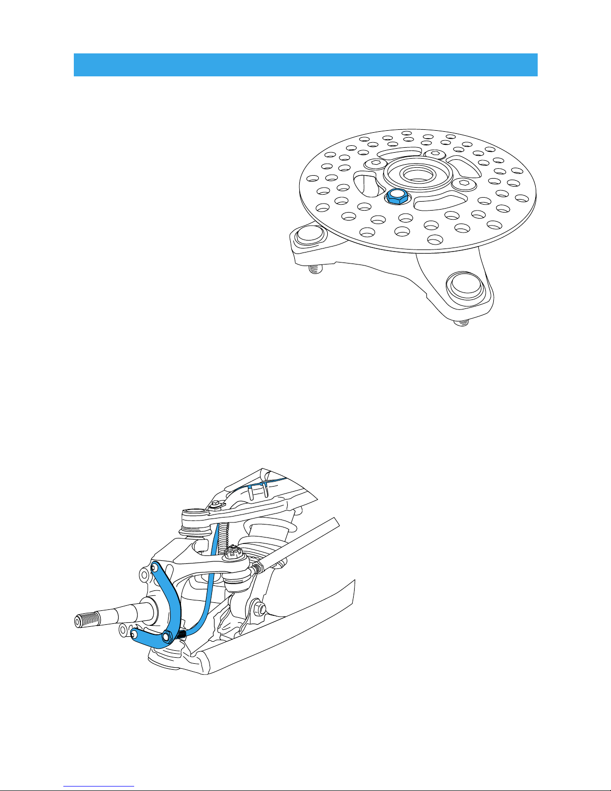
ATV Sensor/Magnet Installation:
Lynx needs two things to be
able to collect data:
1. A magnet placed on the
spinning part of the wheel.
2. The sensor, placed on the
non-moving part of the wheel.
The magnet spins around
tripping the sensor switch each
time—data collected lets Lynx
calculate distance and time.
The magnet gets installed
on the brake rotor because it spins with the wheel. Typically the
provided magnetic bolt can simply replace a stock rotor bolt (see
above picture). If that doesn’t work, there is a spare magnet that
can be glued in a hole
on the brake rotor.
(JB Weld or a similar
slow-cure epoxy works
well.)
After the magnet is in,
the sensor is placed
on a non-spinning part
of the wheel.
The sensor typically is
placed on either the
provided C-bracket or
the ATV metal rotor
shield.
Installation
Magnetic Bolt Installation
ATV Rotor
C-Bracket Installation–ATV Left Axle
14
Page 17
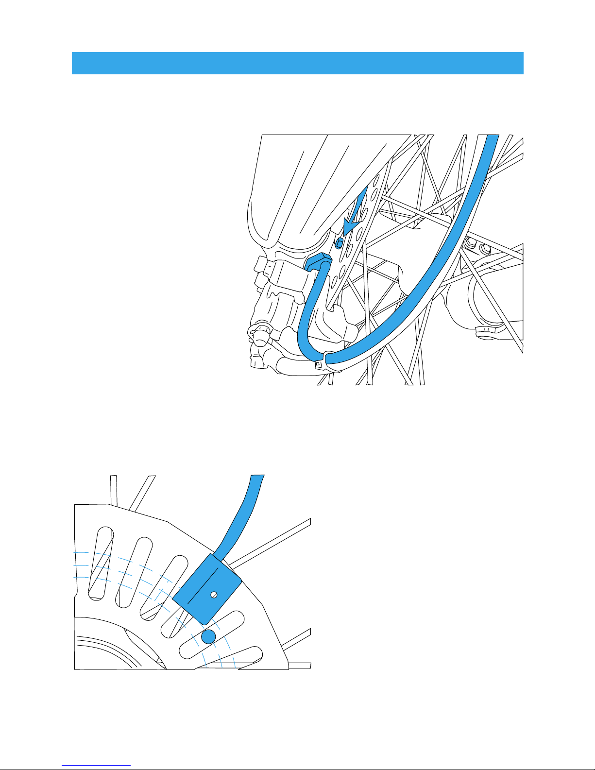
Motorcycle Sensor/Magnet Installation:
Motorcycles, like ATVs,
need a magnet placed
on the spinning part
of the wheel and the
sensor installed to a
non-spinning part.
The magnet typically
gets bolted or glued to
the brake rotor.
The sensor wire
should come from the
back of the computer,
be cable-tied to the
brake line as it travels
down the front forks,
then attached to the brake caliper.
Lynx can tell how far and
fast it’s travelled by keeping
track of how many times the
magnet passes under the
sensor switch.
Many Motorcycles and ATVs
have special installation
procedures. Refer to the
provided installation insert
for specific instructions for
your machine or visit
www.TrailTech.net.
Installation
Magnet About to Pass Under Sensor
Optimum Magnet Rotation Path
15
Page 18

Overview:
You will use the wheel size number when setting up the computer
for your machine. Use Method 1, 2 or 3.
Method 1)
Easy Ruler
Method:
Find the
circumference
of front wheel
by measuring
its diameter in
millimeters. Multiply
the Wheel Diameter by
3.14. The result is your
wheel size.
Method 2)
Rolling Measurements:
On a flat surface, mark the tire sidewall and the ground with a
marking pen. Roll the wheel until the mark on the tire completes
one revolution and is back on the ground. Mark the ground at this
location. Measure the distance between the marks on the ground
and convert the measurement to mm (multiply inches by 25.4). Use
this number for your wheel size. For accuracy, the riders weight
should be on the bike when making this measurement.
Measure Wheel Size
Diameter(mm)
x 3.14
Wheel Size =
Wheel Diameter(mm)
x 3.14
16
Page 19

Measure Wheel Size
Method 3) Distance Measurements:
For the most accurate measurement, use wheel size measure-
ment from above or set the wheel size to 2109mm (motorcycle),
1675mm(ATV) and follow this procedure:
1. Find a length of road where the distance is known.
2. Ride the distance and note the distance the computer reads (for
example, the road is known to be 5 miles and the computer shows
4.95 miles).
3. Use the numbers to solve for X in the following equation:
2109
=
4.95
or
(current wheel size)
=
(current miles)
X 5.00 (new wheel size) (actual miles)
4.95X = 2109 * 5.00
4.95X = 10545
X =
10545
4.95
X = 2130
4. Enter number found from the above method in your computer.
My Wheel
Size:
17
Page 20

Data Setting Mode
Overview:
Data Setting Mode is very important for Lynx to operate correctly.
Choose between kilometers or miles per hour, set the wheel size,
choose between 12 hour or 24 hour clock formats, and set the time
of day.
In Data Setting Mode, the buttons on the main computer body must
be used. If no button is pressed for 15 seconds, Lynx will return to
normal mode.
After a setting is confirmed, Lynx will move to the next setting in
order.
18
Page 21

Enter Data Setting Mode:
TO ENTER DATA SETTING
MODE, HOLD + +
Lynx will light up
all the pixels to
make sure they are
working.
Release buttons to
continue.
Program Kilometers or Miles per Hour:
TO CYCLE BETWEEN M/H AND KM/H, PRESS
TO CONFIRM, PRESS
Lynx will go to the next setting.
Data Setting Mode
19
Page 22

Program Wheel Size:
Lynx needs to know wheel size in order to measure Distance and
Speed. Please take the time to accurately measure wheel size for
smooth operation.
USE AS DEFAULTS:
MODIFY FLASHING DIGIT BY PRESSING
CHANGE TO NEXT DIGIT BY PRESSING
TO CONFIRM, PRESS
Lynx will go to the next setting.
Data Setting Mode
MOTORCYCLE—2110MM
ATV—1675MM
20
Page 23
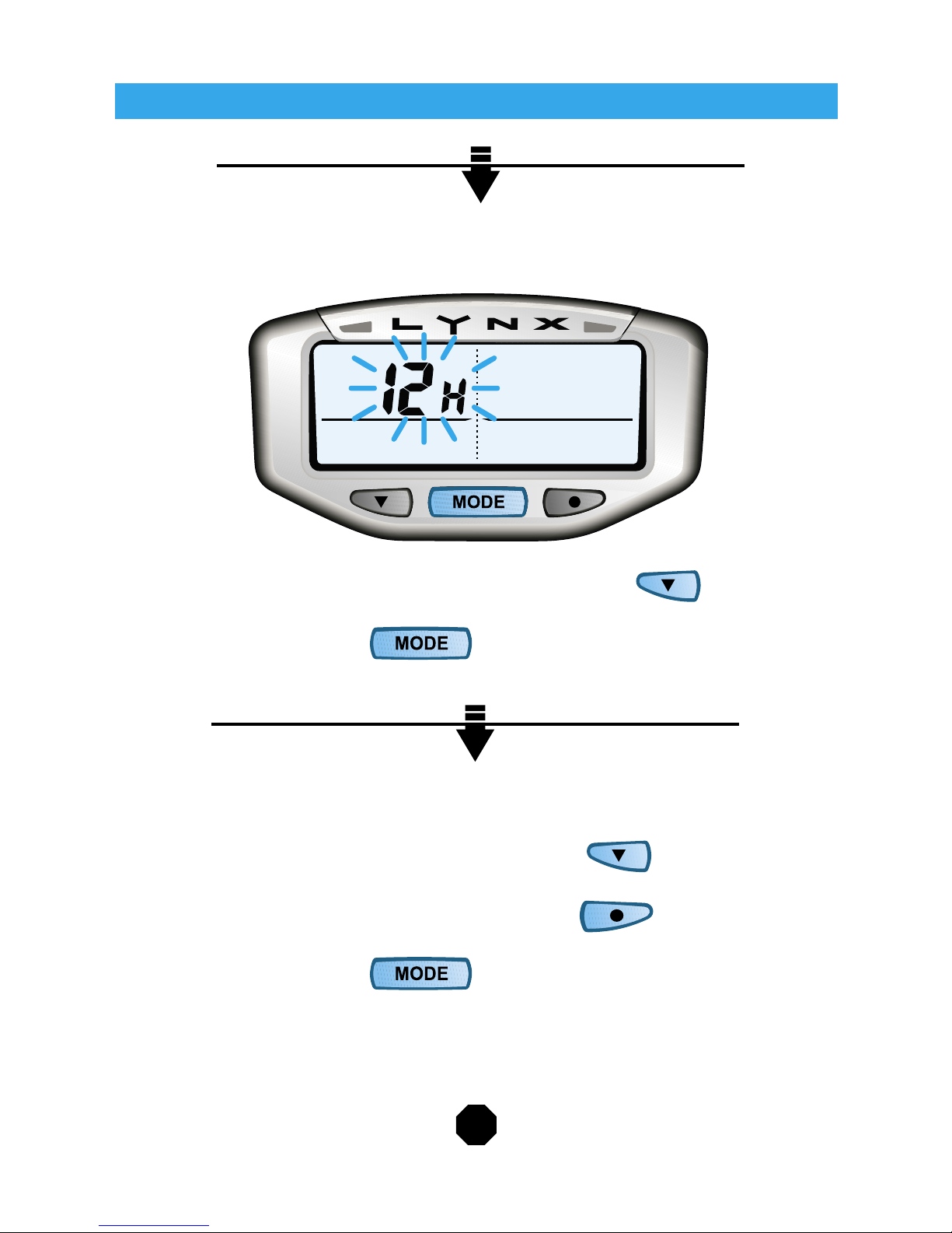
Program 12 or 24 Hour Clock Format:
Lynx defaults to 12 H Format.
TO CYCLE BETWEEN 12 H AND 24 H, PRESS
TO CONFIRM, PRESS
Lynx will go to the next setting.
Program Time of Day:
MODIFY FLASHING DIGIT BY PRESSING
CHANGE TO NEXT DIGIT BY PRESSING
TO CONFIRM, PRESS
Do not press any buttonsLynx will return to Normal Mode after 15 seconds.
Data Setting Mode
21
Page 24

Overview:
Keep track of your ride! Normal information that Lynx tracks can be
found on one of these three screens:
SWITCH BETWEEN SCREENS IN
NORMAL MODE BY PRESSING
Lynx will not stay on Screen 3 while vehicle is moving. It will return
to Screen 1.
Screen 1:
Normal Mode
Speed (SPD) Distance (DST)
Time of Day (Clock) Ride Time (RT)
22
Page 25

Screen 2:
Screen 3:
Normal Mode
Average Speed (AS) Trip Distance (DST)
Time of Day (Clock) Stop Watch (TT)
Max Speed (MS) Odometer (ODO)
Time of Day (Clock) Accumulated Ride Time (ART)
23
Page 26

Reset Ride Data to Zero:
Reset Ride Data at the end of each ride so new information can be
tracked on the next ride.
Resetable Ride Data includes: Trip Distance (DST), Ride Time
(RT), Maximum Speed (MS), Average Speed (AS), and Stop Watch
(TT).
The Odometer (ODO) and Accumulated Riding Time (ART) cannot
be reset; they are long-term statistics.
TO RESET RIDE DATA, HOLD + OR +
Stop Watch (TT):
TO START OR STOP THE STOP WATCH, PRESS OR
Resetting Ride Data will reset the Stop Watch. Distance, Ride
Time, Max Speed and Average Speed will also be reset.
Normal Mode
24
Page 27

Sleep Mode
Sleep & Wake Up:
If Lynx does not sense movement for 20 minutes, it will enter Sleep
Mode. When in Sleep Mode, Lynx only displays the time of day
clock. As soon as a button is pressed or a wheel turns, Lynx will
wake up.
Sleep Mode is the same for all computer modes (Normal Mode,
Enduro Mode, and Lap Timer Mode.)
Lynx in Sleep Mode
LYNX ENTERS SLEEP MODE AUTOMATICALLY
PRESS ANY BUTTON TO EXIT SLEEP MODE
25
Page 28

Enduro Mode
Enduro Mode can only be entered with the Remote Switch.
Overview:
This enhanced feature set is designed for the enduro or dual sport
eventer. Adjust distance and pace information, then the Delta Timer
will tell you if you are within your “minute”, behind, or ahead.
Enter & Exit Enduro Mode:
TO ENTER OR EXIT ENDURO MODE, HOLD
A circle appears on screen to show Lynx is in Enduro Mode.
26
Page 29

Enduro Mode
Enduro Screen:
In Enduro Mode, Lynx displays:
Speed (SPD) Distance (DST)
Delta Timer (DT) Stop Watch (TT)
Pace LEDs
Note: Pace LED’s will only light if the computer is connected to
vehicle power.
27
Page 30

Enter Enduro Data Setting Mode:
TO ENTER ENDURO DATA SETTING MODE, PRESS
Set Adjustable Distance:
Input distance adjustments. Make adjustments in tenths. The
longer the button is held down, the faster Lynx will scroll through
numbers.
TO INCREASE BY 0.1, PRESS
TO DECREASE BY 0.1, PRESS
TO CONFIRM, PRESS
Enduro Mode
28
Page 31

Enduro Mode
Set Adjustable Average Speed:
Input speed adjustments. Lynx defaults to 10 M/H.
TO INCREASE BY 0.1, PRESS
TO DECREASE BY 0.1, PRESS
TO CONFIRM, PRESS
Lynx will return to Enduro Mode.
29
Page 32

GREEN LEDRED LED
Delta Timer:
The Delta Timer tells the rider how close to pace they are. Lynx
compares the real time speed & distance to the preset pace to see
how the ride is going.
AHEAD OF MINUTE: Lynx will show a positive Delta Timer num-
ber and turn on the Green LED.
BEHIND MINUTE: Lynx will show a negative
Delta Timer number and turn on the Red LED.
ON MINUTE: (Delta Timer between 0 and -60 seconds),
Lynx alternates flashing the Red and Green LEDs.
To set Delta Timer (DT) to 0:00:00, Hold
Stop Watch (TT) will not reset when Delta Timer is reset.
Enduro Mode
30
Page 33

RIDER AT DEPARTURE POINT:
Reset Enduro Ride Data:
Reset Enduro Ride Data at the beginning of each race so new
information can be gathered.
Resetable Enduro Ride Data includes: Delta Timer (DT), Stop
Watch (TT), and Distance (DST).
TO RESET ENDURO RIDE DATA, HOLD +
Key Time—
Start Timers and Data Collection:
Remember that the Delta Timer and Stop Watch can only be
stopped by pressing the left button on the main computer body.
This will prevent accidental turn off during the race. Once the left
button on the main computer has been pressed, the computer
stops logging race data. Do not use the left button on the main
computer for “Free Time”.
If race data collection has been stopped by pressing the left button,
it will resume if rider presses the top button of the remote switch.
TO START ENDURO TIMERS, PRESS
Enduro Mode
31
Page 34

RIDER AT CHECKPOINT:
Make Adjustments:
At each checkpoint, make Adjustable Distance (ADST) and Adjustable Average Speed (AAS) adjustments. Use the route chart to
enter correct values for the next leg of the race.
Automatic Wheel Size Adjustment:
On many courses, the rider is given a mileage marker early into the
race as an opportunity to calibrate their timekeeping device with
the course mileage. When the first distance adjustment is made
on Lynx, the computer will display a suggested wheel size setting
for 5 seconds. Press the middle button on the remote to accept the
suggestion.
TO ACCEPT WHEEL SIZE SUGGESTION, PRESS
Lynx will save the new Wheel Size Setting.
Free Time:
Press center button once on main computer to stop Delta Timer
during a lay-over or “Free Time.” Note that Stop Watch will con-
tinue to run. Re-start Delta Timer by pressing center button again.
TO STOP DELTA TIMER FOR FREE TIME, PRESS
TO START DELTA TIMER AGAIN, PRESS
Enduro Mode
32
Page 35

RIDER AT END OF RACE:
Pause Timers and Data Collection:
At the end of the race, Lynx needs to be told to stop collecting
data. Stop race data collection by pressing the left button on the
computer body once. Rider can restart data collection by pressing
upper button on remote switch. When rider presses middle button
on remote to leave Enduro Mode, all collected data is erased.
TO STOP DATA COLLECTION, PRESS
Exit Enduro Mode:
After finishing riding Enduro, return to Normal Mode.
Enduro data will be reset when Lynx goes to Normal Mode.
TO EXIT ENDURO MODE AND RETURN TO
NORMAL MODE, HOLD FOR 2 SECONDS.
When Lynx stops displaying the Special Mode Indicator
Symbol ( ), it has switched to Normal Mode.
Enduro Mode
33
Page 36

Enduro Mode
Frequently Asked Questions:
I WILL BE USING THE ENDURO RIDER OR LAP TIMER FEA-
TURES. WHILE IN THESE MODES, WHAT IS HAPPENING TO
THE ODOMETER AND ACCUMULATED RIDE TIME DATA?
Answer: Both odometer and accumulated riding time data is being
gathered while rider is in either optional feature mode. ODO and
ART are only accessible to view when the computer is in Normal
Mode.
IF I DO NOT ENTER A DESIRED AVERAGE PACE, WHAT WILL
THE COMPUTER DO?
Answer: It will default to the last entered number. If no number has
been entered, the computer has a default setting of 10.
WHAT HAPPENS IF I HAVE PROBLEMS DURING AN EVENT,
AND MY WHEEL IS NO LONGER TURNING.
Answer: Stop Watch and Delta Timer continue to log time when
wheel is not turning.
IS IT POSSIBLE TO STOP JUST THE DELTA TIMER?
Answer: Yes. Delta Timer can be stopped by pressing the center
button the main computer body. Please note that the Stop Watch
(TT) continues to run. When the rider presses the center button the
main computer again, the Delta Timer will resume.
34
Page 37

Enduro Mode
WHAT IF I BLOW BY A CHECK DURING AN EVENT? CAN I
ADJUST MY DELTA TIMER?
Answer: Yes. If the rider misses a posted speed or distance
change, the delta timer will become inaccurate. To correct the delta
timer, the rider can adjust by holding the down button on the remote
switch for 3 seconds. This will bring the rider into an up/down
adjustment mode for the delta timer. The adjustment will be in seconds. The longer the rider holds the button, the faster it will adjust.
To leave DT adjust, press the middle button on the remote once.
35
Page 38

Frequently Asked Questions:
WHAT IS MOTORCYCLE ENDURO RACING EXACTLY?*
Enduro racing brings nature, man and machine together in a grand
adventure to find the best rider. Enduro racing combines the main
skills used in other major forms of motorcycling: Speedway, Road
Racing, Motocross & Trials.
Putting in a full day of work, the riders navigate through trails, old
roads, tracks, and wherever else a motorcycle can go. The course
gets broken into many checkpoints where the riders should arrive
at the specified time. Riders get penalized points for each minute
early or late they check in.
Riders getting to the checkpoints early can wait until the specified
time before checking in and continuing on. While waiting they
perform maintenance on their bikes and get refueled.
During the day between normal checkpoint legs are the special
stages. This is where most of the exciting action happens. Riders
are penalized points for every second it takes them to complete the
special stage. They must go as fast as possible in an all-out bid to
win.
The rider who gets the least amount of points for the day wins.
*Rules Will Vary
Enduro Mode
36
Page 39

37
Enduro Mode Example:
DISTANCE RESETS—
ROUTE CHART SPECIFIES A MILEAGE JUMP OF 0.5 MILES TO
92.5 MILES.
The race is underway. Delta Timer (DT) is at -10 seconds.
Adjustable Average Speed (AAS) is set to 20 M/H. Both LED’s are
flashing, indicating rider is on his minute.
The rider needs to change the Adjustable Distance from 92.0 to
92.5. Enter Enduro Data Setting Mode by pressing .
Increment from 92.0 to 92.5 by pressing five times.
Return to main Enduro Mode screen by pressing twice. The
Delta Timer (DT) accounts for the distance advance. Note steady
green LED indicating rider is ahead of their minute.
Discussion:
Rider makes the distance adjustment. The computer calculates
that the rider has advanced 1:30 ahead ((0.5/20*60). The computer
adds this one time adjustment to the current Delta Timer (DT). Ad-
justable Average Speed (AAS) has not changed, and remains at 20.
Note: Delta Timer assumes that being “on your minute” means
there is a sixty second window. When Delta Timer (DT) shows
00:00, this means the rider is at the top of their minute. If Delta
Timer (DT) shows -00:59, they are at the bottom of their minute.
Enduro Mode
Page 40

Lap Timer Mode
Lap Timer Mode can only be entered with Remote Switch.
Overview:
This enhanced feature set is designed for race riders and time trials.
Hit the lap counter button each time around the track–compare lap
times on the fly with colored pace lights, or wait and review precise
lap information afterwards.
Enter & Exit Lap Timer Mode:
TO ENTER OR EXIT LAP TIMER MODE,
HOLD + FOR 3 SECONDS.
A circle appears to show Lynx is in Lap Timer Mode.
38
Page 41

Lap Timer Mode
Lap Timer Screen:
In Lap Timer Mode, Lynx displays:
Speed (SPD) Distance (DST)
Lap Counter Stop Watch (TT)
Pace LEDs
Note: Pace LED’s will only light if the computer is connected to
vehicle power.
39
Page 42

Pace Lights:
Lynx keeps track of how fast each lap has been run. At the begin-
ning of Lap 3, the red and green LEDs will start lighting up. Green
means faster, red means slower. Solid means that the lap was
faster or slower, but a blinking light means it was either the fastest
or slowest lap yet.
LED comparison information is accurate to the second. When the
rider completes two identical laps (down to the second), neither
LED will light up.
GREEN LEDRED LED
Lap Timer Mode
40
Page 43

Pace Light Examples:
Example 1: Rider completes Lap 1 in 12 minutes and completes
Lap 2 in 9 minutes. At the beginning of Lap 3, the green LED will
flash for five seconds. Second lap was both faster than Lap 1 and
the fastest yet recorded.
Example 2: Rider completes Lap 2 in 9 minutes and completes Lap
3 in 11 minutes. At the beginning of Lap 4, the red LED will light for
five seconds.
Example 3: Rider completes Lap 3 in 11 minutes and completes
Lap 4 in 10 minutes. At beginning of Lap 5, green LED will light
for five seconds to indicate Lap 4 was faster than Lap 3 but not the
fastest lap yet.
A steady on green light means the last lap was fast, but not the
fastest yet.
Lap Timer Mode
41
Page 44

RIDER AT DEPARTURE POINT:
Reset Lap Timer Data:
Reset Lap Timer Data at the beginning of each race so new infor-
mation can be gathered. Lap Timer Data can only be reset from
within Lap Timer Mode.
Lap Timer Data includes: Lap Counter, Average Speed (AS), Distance (DST), and Stop Watch (TT).
TO RESET LAP TIMER DATA, HOLD +
Start Lap Timer:
Press upper button on remote switch once to activate Lap Timer.
Lap Timer will wait for two wheel revolutions before collecting data;
this way the rider can activate the timer while waiting on the start
line, but before the actual start signal.
TO START LAP TIMER, PRESS
Lap Timer Mode
42
Page 45

DURING RACE:
Rider Starts New Lap:
At the beginning of each new lap, press once. This will end Lap
1 and start Lap 2. Continue in this fashion until the last lap.
AT THE START OF EACH NEW LAP PRESS
RIDER AT FINISH LINE:
Pause Timers and Data Collection:
When the last lap has been completed, press once to stop last
lap, and stop Lap Timer data collection.
TO STOP LAST LAP, PRESS
Enter & Exit Lap Timer Mode:
TO ENTER OR EXIT LAP TIMER MODE, HOLD +
Lap Timer Mode
43
Page 46

LAP TIMER REVIEW:
Lap Information:
The rider can look at Lap information when vehicle is stopped and
Lap Timer is paused.
TO SCROLL THROUGH INDIVIDUAL
LAP INFORMATION, PRESS
Lap 2 Information
Lap Timer Mode
44
Page 47

Cumulative Lap Information:
Lynx also shows Race Stats (all the laps’ stats added together).
TO SCROLL THROUGH
CUMULATIVE RACE STATS, PRESS
Average Speed, Average Distance & Average Lap Time for All Laps
Max Speed For All Laps, Total Distance Recorded
& Total Time Recorded
Lap Timer Mode
45
Page 48

Troubleshooting
Check the following before taking the unit to repairs:
PROBLEM CHECK ITEMS REMEDY
No Display 1.Is the battery dead?
2.Is the battery in-
stalled correctly?
1.Replace the battery.
2.Make sure that the
positive (+) pole of the
battery is facing up.
No Current
Speed or
Incorrect
Data
1.Is the computer in
set-up mode?
2.Are the contacts
between the main unit
and the bracket poor?
3.Is the wheel
measurement correct?
4.Are the relative
positions and gap
between sensor and
magnet correct?
1.Refer to the data
setting procedure and
complete the adjustment.
2.Clean the contacts.
3.Refer to Wheel
Measurement section
and enter correct value.
4.Refer to Sensor
Installation section and
install correctly.
Irregular
Display:
LCD is
Black
Did you leave the computer in direct sunlight
when not riding for a
long while?
Press the reset button
on back of the computer.
Place the computer in
the shade.
Display is
Slow
Is the temperature
below 0°C (32°F)?
Lynx will return to
normal when the
temperature rises.
46
Page 49

Troubleshooting
PROBLEM CHECK ITEMS REMEDY
Backlight
Will Not
Light For
More Than
3 Seconds.
Is Lynx properly
connected to the
vehicles 12 volt
system?
Check docking station
cables and make
sure they are solidly
connected to 12 volt
battery terminals.
Pace Lights
Will Not
Light Up
Is Lynx properly
connected to the
vehicles 12 volt
system?
Pace lights will not turn
on if using the internal
battery.
Check docking station
cables and make
sure they are solidly
connected to 12 volt
battery terminals.
Cannot
Enter Lap
Timer or
Enduro
Modes
1.Is the optional
remote switch installed
properly?
2.Are the buttons
working properly?
The optional remote
is required to use Lap
Timer and Enduro
Modes.
1.Make sure all wires
are undamaged and
correctly installed.
2.Hold down the middle
button on the optional
remote for 5 seconds to
enter Enduro Mode.
47
Page 50

Glossary of Terms
ACCUMULATED RIDE TIME (ART)
The long-term total amount of time spent riding (all ride times added
together). Cannot be reset.
ADJUSTED AVERAGE SPEED (AAS)
Part of Enduro Mode’s programmable pace. User can enter speed
adjustments during an event.
ADJUSTED DISTANCE (ADST)
Part of Enduro Mode’s programmable pace. User can enter
distance adjustments during an event.
AVERAGE SPEED (AS)
The mean speed of the vehicle since the last reset.
BACKLIGHT
The light that brightens up Lynx’s display. Press the left button to
activate it. It is 5 times brighter and continuous if connected to a
machines power.
DATA SETTING MODE
The place to set the computer to KM/H or M/H, wheel size, 24 or 12
hour format, and time of day.
48
Page 51

Glossary of Terms
49
DELTA TIMER (DT)
Enduro Mode feature that tracks riders progress during an event,
taking into account Adjusted Distance and Average Speed settings.
The Delta Timer then determines if they are on their minute, ahead,
or behind.
DISTANCE (DST)
The amount of trail covered since the last reset.
ENDURO MODE
This enhanced feature set is designed for the enduro or dual sport
eventer. Adjust distance and pace information, then the Delta Timer
will tell you if you are within your “minute”, behind, or ahead. Can
only be activated with the optional remote switch.
LAP TIMER
Keeps track of how many laps have been run, information on each
lap and cumulative information for all laps.
LAP TIMER MODE
This enhanced feature set is designed for race riders and time trials.
Hit the lap counter button each time around the track–compare lap
times on the fly with colored pace lights, or wait and review precise
lap stats afterwards. Can only be activated with the optional
remote switch.
MAGNET
Made of Rare Earth, the magnet works with the sensor to let Lynx
collect its data. It gets mounted to the turning part of the wheel and
every time it goes around it triggers the sensor (thereby collecting
distance and speed information).
Page 52

Glossary of Terms
50
MAXIMUM SPEED (MS)
The highest speed attained since the last reset.
NORMAL MODE
Keep track of your ride! Normal Mode is plenty for the average
recreational rider. Lynx tracks a variety of useful information in
Normal Mode including: Speed, Distance, Time of Day, Ride Time,
Average Speed, Trip Distance, Stop Watch, Max Speed, Odometer
and Accumulated Ride Time.
ODOMETER (ODO)
Keeps track of the total distance the vehicle has travelled since
installing the computer. Cannot be reset.
REMOTE SWITCH
Optional accessory that mounts to the handlebars and allows entry
into both Enduro and Lap Timer Modes.
RESET BUTTON
Resets all saved information. Located on the back of the computer.
RIDE TIME (RT)
Total time spent riding since the last reset.
SENSOR
Works with the magnet to let Lynx collect its data. It gets mounted
to the non-turning part of the wheel. Every time the magnet goes
around, it triggers the sensor (thereby collecting distance and
speed information).
Page 53

Glossary of Terms
51
SLEEP MODE
If Lynx doesn’t receive any sensory information it will go into Sleep
Mode and only display the clock. Press any button to exit.
SPEED (SPD)
The current speed the vehicle is travelling.
STOP WATCH (TRIP TIME) (TT)
A short-term, regular stop watch.
WHEEL SIZE
Very important. Used to determine speed and distance. Refer to
the Wheel Measurement section for an accurate measurement.
Page 54

Notes:
Notes
52
Page 55

Page 56

LIMITED WARRANTY
Within 180 days from the date of original purchase, TrailTech will
repair or replace, at its option, any TrailTech Motorsport Computer
which is deemed defective in workmanship or materials.
Please return the unit, together with proof of date of purchase, to
your local dealer or send unit (postage paid) to TrailTech.
Damage or injuries resulting from negligence or misuse are not
covered by this warranty. Incidental or consequential damages are
specifically excluded.* This warranty gives you specific legal rights.
You may also have other rights which vary from state to state.
* Because some states do not allow the exclusion of incidental or
consequential damages, this exclusion may not apply to you.
TrailTech and Lynx are
trademarks of TrailTech, Inc.
www.TrailTech.net
360-687-4530
 Loading...