

1. POWER OVERVIEW
Endurance II can run on the internal 3.0V watch type
battery (#CR2032).
Install the power wire to enable the continuous backlight.
Endurance II is polarity independent and has safeguards
to avoid draining the vehicle battery. See the POWER
CONNECTION section for more info.
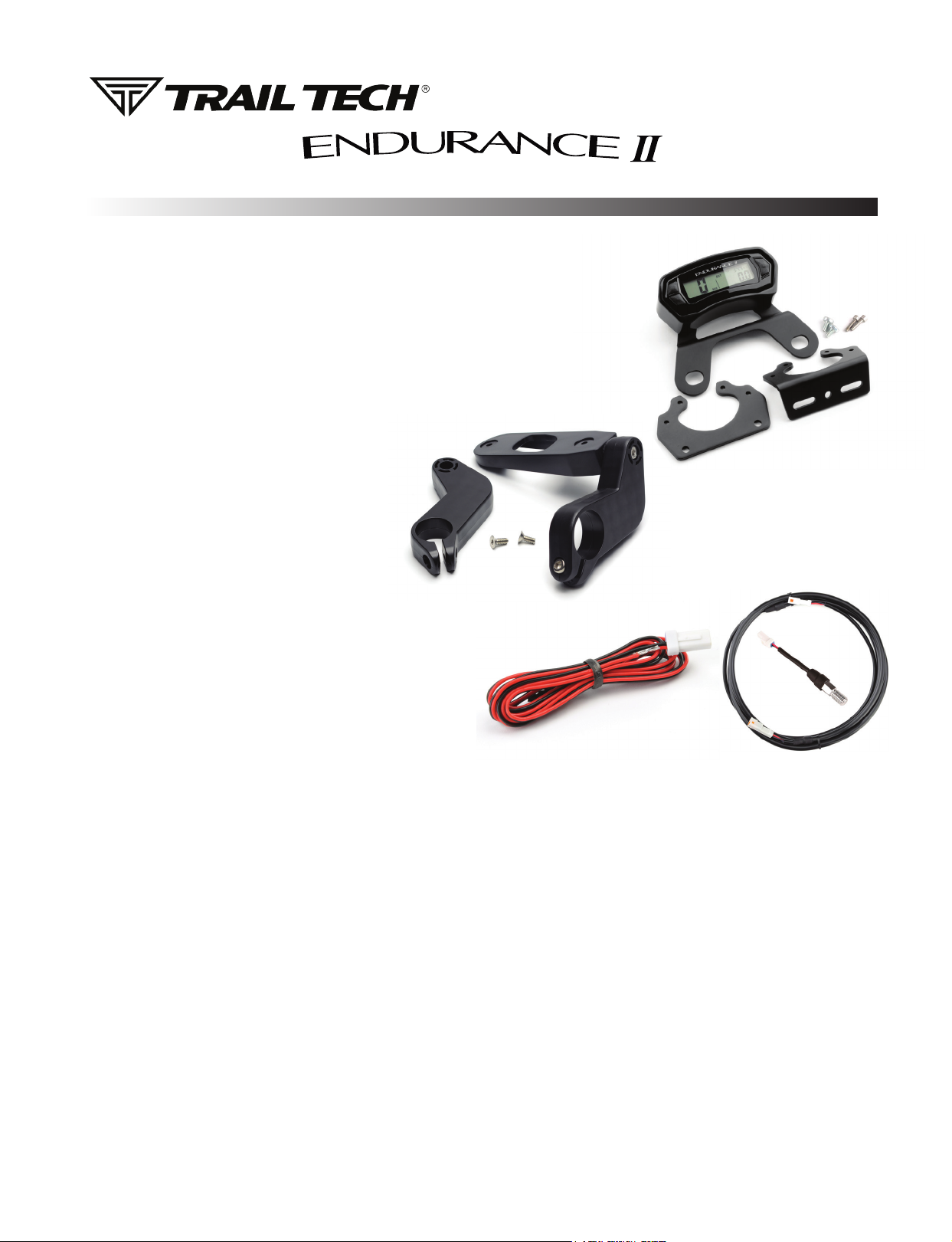
2. MOUNT ENDURANCE II:
Endurance II is made to be bolted to the vehicle. Use
the included handlebar mounts, or refer to the manual
or www.trailtech.net for other options like the CNC
aluminum protector.
Tech Support: (844) 378-8143
010-ELV-197
technicalservice@apexproductgroup.com
QUICK-START
Aluminum
Protector Mount
(optional)
Included
Handlebar
Mount
3. VEHICLE SENSORS:
Refer to the sensor installation sections. You should install
both the wheel sensor and vehicle power connection.
Installing the power wire enables a continuous and brighter backlight.
Installing the wheel sensor enables speed and distance readouts.
Power Wire Wheel Speed
4. MAINTENANCE REMINDER:
Endurance II’s maintenance icon appears after the countdown gets to 0. Increase the countdown in DATA SETTING MODE.
The countdown can be based on either DISTANCE or TIME, select your preference in DATA SETTING MODE.
5. SLEEP MODE:
Endurance II goes to sleep if no vehicle activity is detected.
During sleep mode Endurance II uses the internal battery and will not draw down vehicle power.
a. Wakes on external power
b. Wakes on wheel movement
c. Wakes on button press
d. Backlight shuts off after 90 seconds of inactivity
e. LCD shuts off and clock is displayed after 180 seconds of inactivity.
Sensor (varies)
QUICK-START
6. BUTTONS:
Endurance II has three screens. Press MODE to toggle between them.
Button 3
Next
Button 1
Increment
Up
Button 2
Decrement
Down
RESET TRIP DATA:
<LEFT> + <MODE> = HOLD TO RESET VALUES FOR:
Max Speed, Distance, Ride Time
ADJUST TRIP DISTANCE:
<MODE> + 3 sec = ENTER ADJUST MODE
<LEFT>, <RIGHT> = SCROLL VALUE
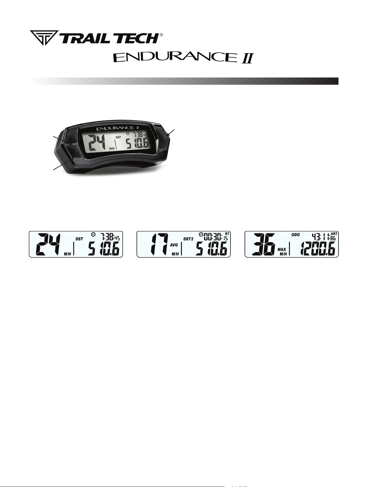
7. SCREENS:
Endurance II has 3 screens, press BUTTON 3 to cycle between screens. Hold all three buttons to enter data setting mode.
SCREEN 1
• Speed
• Trip Distance 1
• Clock
SCREEN 1 BUTTONS:
• Press and hold buttons 1 & 2 for three
seconds to reset DST.
• Press and hold button 3 to enter DST
adjustment. Use buttons 1 & 2 to increment
and decrement your DST. Press button 3 to
return to main screen.
• Speed - Average
• Trip Distance 2
• Ride Time
SCREEN 2 BUTTONS:
• Press and hold buttons 1 & 2 for three
seconds to reset DST2, Ride Time, & AVG
Speed.
• Press and hold button 3 to enter DST2
adjustment. Use buttons 1 & 2 to increment
and decrement your DST2. Press button 3
to return to main screen.
SCREEN 2
SCREEN 3
• Speed - Max
• Odometer (ODO)
• Accumulated Ride Time (ART)
SCREEN 3 BUTTONS:
• Press and hold buttons 1 & 2 to reset
Max Speed.
• To view time remaining until service
maintenance interval icon is activated
press and hold Button 3 for three
seconds.
• When the maintenance icon is
displayed, hold button 3 for three
seconds to enter maintenance interval
screen (to reset, hold button 1 & 2 for
three seconds.)
8. DATA SETTING MODE :
HOLD DOWN ALL 3 BUTTONS to enter data setting mode.
Adjust one setting at a time, then move on to the next one.
<BUTTON 1> = Increase value
<BUTTON 2> = Decrease value
<BUTTON 3> = Move to next data setting screen
ORDER OF SETUP MODE:
1. Speed and Distance Format
2. Wheel Size
3. Time Format
4. Time of Day
5. Maintenance Format
6. Maintenance Countdown
M/H or KM/H
See MEASURE WHEEL SIZE section
12H or 24H
12:00:00
Based on ODO Distance or ART Time
Distance or Time to Countdown From

WHEEL SENSORS
INSTALLS
KTM WHEEL SENSOR
Trail Tech wheel
sensors work with the
KTM and Husqvarna
OEM install location.
Screw the wheel
sensor into the OEM
caliper position. Insert
the black magnet into
the pre-drilled hole in
the rotor and secure
with the retainer clip.
KTM Magnetic
Retainer
KTM OEM Wheel
Sensor Position
INVERTED FORK WHEEL SENSOR
If there are fork
guards next to the
brake rotor, then the
fork guard wheel
sensor can be
installed as shown.
Try to have the tip of
the sensor about 1/2
inch away from the
magnet in the rotor.
Rotor Bolt Magnet Inverted Fork
Wheel Sensor
CONVENTIONAL FORK SENSOR
If the fork is close to
the brake rotor, then
the VHB fork sensor
can be used. Peel
and stick the sensor
to the fork.
Try to have the tip of
the sensor about 1/2
inch away from the
magnet in the rotor.
Rotor Bolt Magnet Conventional Fork
VHB Wheel Sensor
ROTOR SHIELD WHEEL SENSOR
For UTVs and quads
with a rotor shield,
position the sensor
there.
Drill a 3/8” hole and
use the jam nuts to
secure the sensor to
the rotor shield. Use
loctite rather than
over-tightening the
jam nuts.
Rotor Shield
Wheel Sensor
BRAKE CALIPER WHEEL SENSOR
Some ATVs require
mounting the wheel
sensor directly to the
brake caliper.
Drill a 1/8” hole
through the caliper
mount, then use the
self-tapping screw to
secure the sensor.
Brake Caliper
Wheel Sensor
MAGNET INSTALLATION:
Install a magnet on the brake rotor to trigger
the speed sensor each wheel rotation.
Remove one of the stock rotor bolts and
install the magnetic rotor bolt as shown, do
not overtighten past 10 ft-lb of torque. If the
magnetic bolt will not work, the kit includes a
spare magnet that can be installed into one
of the rotor spaces. Use the included retainer
clip or epoxy such as JB Weld to secure.
C-BRACKET WHEEL SENSOR
Some kits include
a metal C-bracket
to help mount the
sensor, as shown.
Use the jam nuts to
secure the sensor to
the C-bracket. Use
loctite rather than
over-tightening the
jam nuts.
Magnetic Retainer or Spare MagnetMagnetic Rotor Bolt
C-Bracket
Wheel Sensor

WHEEL SENSORS
SETUP
WHEEL SENSOR TEST:
Test for correct sensor/magnet placement before permanently mounting.
1. Set the vehicle on a stand so that the front (left) wheel spins easily.
2. Plug the wheel sensor cable into the computer.
3. Install the magnetic bolt.
4. Hold the sensor in place on the caliper mount by hand. While someone
watches the computer, roll the wheel. If the computer does not register,
move the magnet or sensor and try again. There should be 1/2” or less
gap between the sensor and magnet.
Do not mount so that the magnet passes the middle section of the
sensor. Either the sensor will not register at all; or the sensor will
register twice, causing a “double trigger” effect (computer displays
twice the true speed.) If a double-trigger is unavoidable, divide the wheel
size setting in the computer by 2 to correct the problem.
MEASURE WHEEL SIZE:
Knowing your exact wheel size it critical for the wheel sensor to calculate
correct speed and distance data.
Magnet Rotation Path
When comparing calibration to GPS data, use a long straight section of road
with no tight corners or small vertical movements.
Method 1: Ruler
Find the circumference of front wheel by measuring its diameter in millimeters.
Multiply the Wheel Diameter by 3.14. The result is your wheel size.
Method 2: Rolling
On a at surface, mark the tire sidewall and the ground with a marking pen. Roll the
wheel until the mark on the tire completes one revolution and is back on the ground. Mark
the ground at this location. Measure the distance between the marks on the ground in
millimeters (multiply inches by 25.4 to convert to mm). Use this number for your wheel size.
For accuracy, the rider’s weight should be on the bike when making the measurement.
Method 3: Distance Measurement
This is the most accurate method.
1. Set the wheel size to 2110mm (motorcycle) or 1675 (ATV).
2. Find a length of road where the distance is known.
3. Ride the distance, noting how far the computer reads (i.e. the road
is known to be 5 miles and the computer shows 4.95 miles.)
4. Use the numbers to solve for X in the following equation:
(new wheel size)
(actual miles) x (current wheel size)
=
(current miles)
Wheel Size =
Wheel Diameter(mm)
x3.14
Diameter
Generic/Average Sizes:
Motorcycle:
ATV:
2110 mm
1675 mm
Wheel Size:
Enter the number you calculate from one of
the above formulas into setup mode.
x3.14
X =
5 x 2110
4.95
X =
10550
4.95
X = 2131
 Loading...