

Page 1
KICKSTAND INSTALLATION
2012-2014 KTM 125/150/250 SX
2011-2014 KTM 250/350 SX-F 2013-2014 KTM 450 SX-F
STEP 1
Remove cotter pin and washer from left foot
peg pin. Rotate foot peg pin so cotter pin hole is
aligned vertically. If bike has plastic frame guard,
unbolt guard and slide upward out of the way.
(Figure 1)
TRAIL TECH KICKSTANDS
010-ELV-161
Tech Support: 360-687-4530
tech_support@trailtech.net
Figure 2
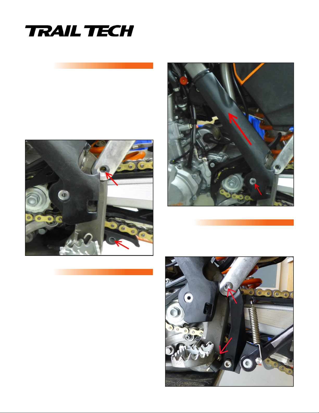
STEP 3
1. Slide kickstand bracket ear between sub-frame
arm and bike frame. Slide kickstand bracket boss
onto foot peg pin.
2. Slide supplied cotter pin through small hole in
kickstand bracket boss and through foot peg pin
hole. Rotate foot peg pin as necessary to align
holes. (Figure 3)
Figure 1
STEP 2
Remove bolt from front lower chain guide. Leave
chain guide in place. Remove bolt from upper subframe arm. (Figure 2)
1
2
Figure 3
Page 2
TRAIL TECH KICKSTANDS
Tech Support: 360-687-4530
tech_support@trailtech.net
010-ELV-161
KICKSTAND INSTALLATION
2011-2014 KTM 250/350 SX-F 2013-2014 KTM 450 SX-F
2012-2014 KTM 125/150/250 SX
STEP 4
Pull sub-frame arm away from bike to allow top of kickstand bracket to move freely. Apply a SMALL
amount of blue thread locker to supplied M8x1.25 bolt. Slide bolt through lower kickstand bracket
mounting hole, front lower chain guide mounting hole, and loosely thread into end of lower shock
mounting bolt. Ensure bolt is partially threaded into end of lower shock mounting bolt before proceeding.
DO NOT thread bolt in completely or snug bolt down.
STEP 5
Apply a small quantity of blue thread locker to
supplied sub-frame arm bolt and install bolt
through sub-frame arm and kickstand bracket
ear into threads on frame. Take care not to crossthread this bolt. The sub-frame arm is often
misaligned with the threaded frame hole and may
require some pressure to line up so that the bolt
may be threaded in straight. The bolt will also not
align if the lower kickstand bolt is fully threaded
in or tightened. Torque sub-frame bolt to factory
recommended torque. See owner’s manual.
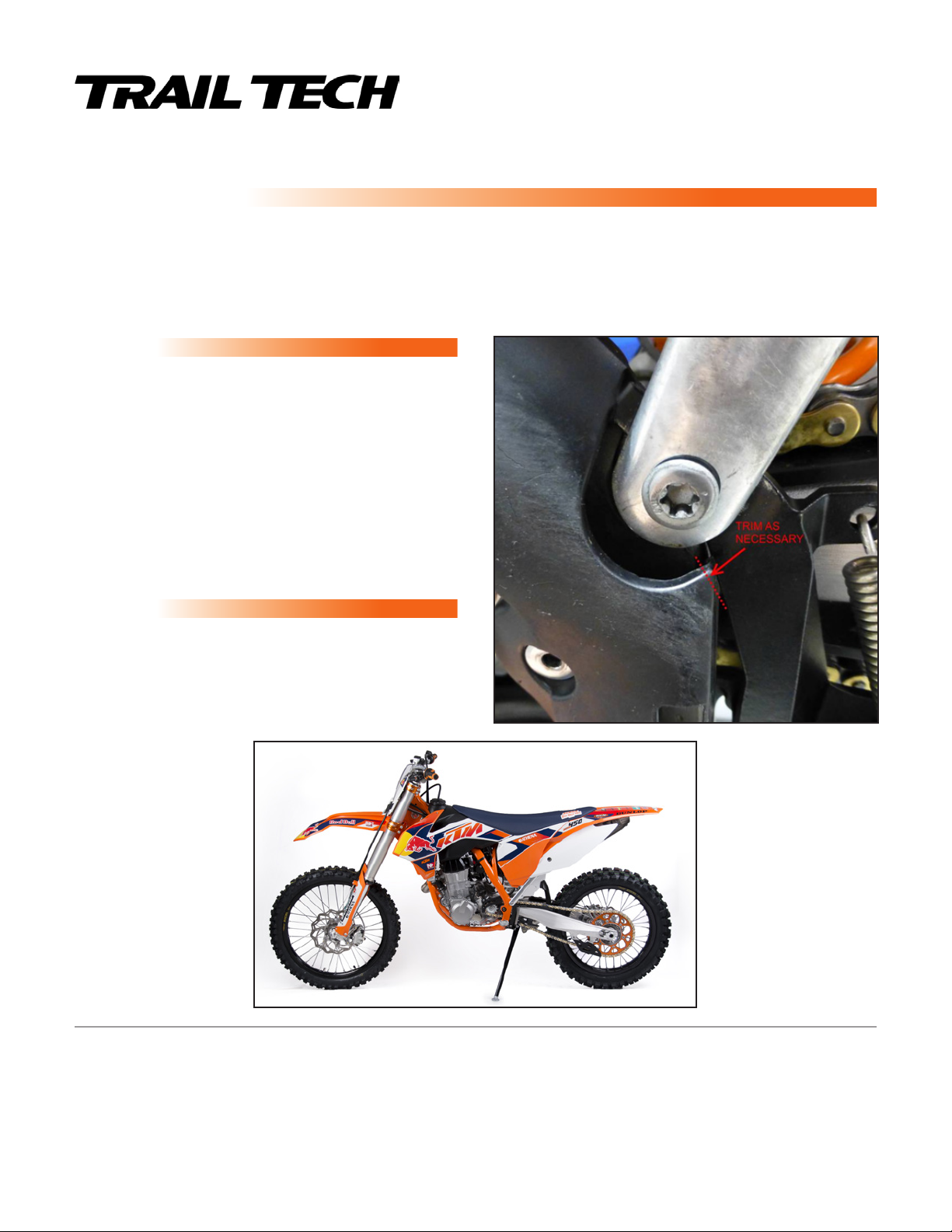
STEP 6
Bend cotter pin ends to secure pin.
Trim corner of plastic frame guard as necessary to
fit between frame and kickstand bracket. Reinstall
guard. (Figure 4)
IMPORTANT: WEAR EYE PROTECTION WHEN HANGING SPRINGS!
Note: After every ride it is important to check your kickstand thoroughly for the following:
• Loose or damaged bolts • Bent or damaged kickstand leg or bracket • Damaged spring
damaged do not ride the machine! Contact a factory trained technician or Trail Tech directly for service or repairs.
TRAIL TECH INC. WARRANTS TRAIL TECH KICKSTAND PRODUCTS TO BE FREE FROM DEFECTS IN MATERIAL AND WORKMANSHIP UNDER NORMAL USE AND IF PROPERLY INSTALLED FOR A PERIOD OF SIX
MONTHS FROM DATE OF PURCHASE. IF FOUND TO BE DEFECTIVE AS MENTIONED ABOVE, IT WILL BE REPLACED OR REPAIRED. THIS SHALL CONSTITUTE THE SOLE REMEDY OF THE PURCHASER AND
THE SOLE LIABILITY OF TRAIL TECH INC. TO THE EXTENT PERMITTED BY LAW, THE FOREGOING IS EXCLUSIVE AND IN LIEU OF ALL OTHER WARRANTIES OR REPRESENTATIONS WHETHER EXPRESSED
OR IMPLIED, INCLUDED ANY LIMITED WARRANTY OF MERCHANTABILITY OR FITNESS. IN NO EVENT SHALL TRAIL TECH INC. BE LIABLE FOR SPECIAL OR CONSEQUENTIAL DAMAGES.
Damaged or broken parts can result in serious injury! If any part of your stand has become
LIMITED WARRANTY
Figure 4
 Loading...