

X2
FEATURES AND WIRING
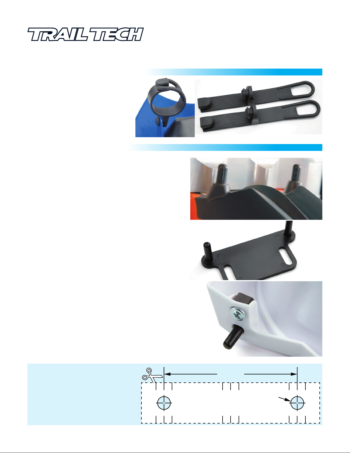
RUBBER MOUNTING STRAPS:
RUBBER MOUNTING STRAPS:
The two rubber straps wrap around the forks.
They hold the light to the motorcycle and
extend the life of the light by providing
anti-vibration isolation. Rubber straps
with no tools. Use isopropyl rubbing alcohol
as lubricant when attaching the rubber straps
to the light. Take care not to rip or tear.
LOWER MOUNTING PINS:
MOUNTING PINS:
There are four holes on the bottom of X2. 2 pins go through the
holes to secure the bottom of X2 to the
the forward or rear holes to aim X2’s beam. The pins reduce
“excessive play” commonly found with other mounting techniques.
There are several pin options:
install
fender. Choose between
010-ELV-75
X2
Tech Support: 360-687-4530
tech_support@trailtech.net
Fig.1
A) O.E.M. MOUNTING PINS:
Some motorcycles (KTM) arrive from the manufacturer
mounting pins built in (Fig.1). If they are present, use them.
B) MOUNTING PLATE:
Some motorcycles (CRF450R, WR450) arrive from the
manufacturer with the fender bolted to the triple tree (with a
56-60mm bolt spacing and M6 bolts.) Sandwich the included
mounting plate
mounting pins for X2. Use Loctite thread locking compound to
ensure the triple tree
C) DOWN-PINS:
If option A or B will not work, use the included “down pins.” To
install, place X2 on the motorcycle using the rubber fork straps.
Turn on X2 and aim the beam to the desired height.
which set of holes to use on X2 (the down-pins are reversible,
side specific, and usually look best if the screw is to the rear of the
light, as shown in Fig.3.) Use a marking pen to mark where two
holes should be drilled in the fender. Remove the light from the
motorcycle and drill the two 8mm (5/16”) holes. Screw the down
pins to X2 as shown in (Fig.3). X2 should now have two pins that
fit into two drilled holes on the fender
The down-pin drill template to the right may
be used if u
1.
Mount X2 using fork straps, align beam angle.
2. With beam angle in place,
on the fender.
template in correct position on fender.
3. Drill down-pin holes a
Drill 1 set of holes ONLY. Drilling 2 sets of
holes can cause fender plastic to break out.
between the triple tree and fender, providing
bolts do not back out during riding.
.
sing the down-pin option.
center X2 right-left
Cut out and tape down-pin drill
nd install X2.
with
Determine
Fig.2
Fig.3
DISTANCE BETWEEN HOLES
82.3mm
(3-1/4”)
DRILL SIZE
8mm
(5/16”)
FEATURES AND WIRING
CABLE GUIDE:
CABLE GUIDE:
To install, thread the cables
through the cable guide, then
screw the cable guide to X2 as
shown to the right.
Be sure the cables are routed properly.
The forks compress a lot during riding,
make sure the cables have enough room
to move up and down without causing damage.
MX bikes should use Enduro brake lines for optimum
X2 fitment.
uses WRF line, etc.
Example: CRF uses CRFX brake line, YZF
010-ELV-75
X2
Tech Support: 360-687-4530
tech_support@trailtech.net
X2
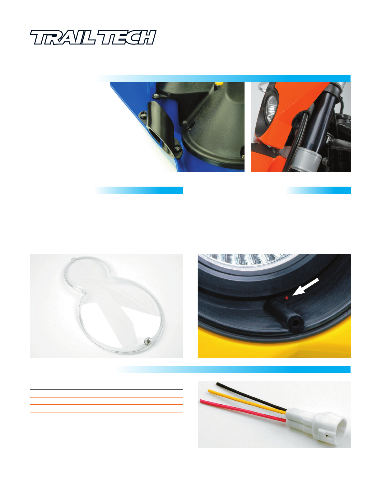
ROCK GUARD:
DEBRIS SHIELD:
Protect X2 from rocks and flying debris. Installs with an
insertion tab and a screw. Intended for racing, the rock
guard is optional. X2 will operate with or without the rock
guard in place. If you run X2 without the rock guard,
avoid gravel roosts. The lamp glass is extremely difficult to
damage, and is optically very clear.
STUB CONNECTOR:
ROCK GUARD VENT:
SILICONE HUMIDITY PLUG:
The rock guard works with a silicone gasket on X2 to create
a water-resistant barrier inside. Occasionally, water may
find its way in. If fogging or moisture buildup occurs, remove
the vent plug (shown below as a red dot.) Use a paper clip
to poke through the silicone vent plug to allow air inside the
light.
still
VENT
PLUG
WIRE COLOR
YELLOW
RED
BLACK
CONNECT TO POWER:
Use the included wire stub connector to connect X2 to
power. The white connector allows for quick disconnect
and removal of X2 from the motorcycle. An on/off switch
is recommended. A fuse (10-20 amp) will protect from any
power spikes.
FUNCTION
HIGH BEAM
LOW BEAM
GROUND
CONTROLS
4” SC4 BULB
2” MR16 BULB
GROUND
This stub connector is included in all X2 kits.
Complete wire harness with on/off switch sold separately.
 Loading...