

BAR CLAMPS & X-BARS INSTALL GUIDE
STOCK BAR REPLACEMENT STEPS:
• If stock grips will not be re-used, it is usually only
necessary to remove the left hand grip.
• To remove the choke assembly (if it is located on
the bars), it is best to separate it from the rubber
boot. To do this, stretch the rubber boot over the
choke lever.
• Remove remaining assemblies from the stock
bars. Pay close attention to how and where they fit
on the bars so that you can easily put them back on
the new bars.
• If the quad has stock indicator lights: Carefully
remove the colored plastic caps with a small screwdriver, then push the rubber boot down through the
hole. To install the rubber boots into the TrailTech
clamp, apply a bead of water for lubrication.
TIP:
Trail Tech Bar Clamps
010-ELV-21
Tech Support: 360-687-4530
tech_support@trailtech.net
Your new Trail Tech X-bar will accept
any standard aftermarket ATV grips.
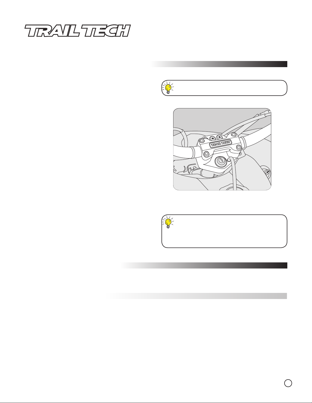
• Attach lower portion of the TrailTech bar clamp to
OEM steering stem. Place 1 1/8” bars in the cradle
and secure with TrailTech top clamp. Some controls
may need to be placed on the bars before the bar is
installed.
TIP:
• If your package includes two black anodized
spacers, they should be placed between the steering stem and the bottom portion of the clamp.
Suzuki Z400, Kawasaki KFX400 & Polaris Predator
BAR CLAMP & X-BARS
INSTALLED ON YAMAHA RAPTOR
TORQUE VALUES:
Use OEM torque specs when attaching clamps to the steering stem.
The four top clamp bolts should be
torqued to 20 ft. lbs.
ADDITIONAL INSTALL INFO:
Some ATVs have special install procedures. See page 2 for more guidance on specific quads.
X-BAR LOCATING HOLES:
OEM bars sometimes include a locating hole to secure control assemblies. The assembly will have a pin that
snaps into the hole, which locks it in place.
To create a locating hole in the X-Bar, follow these steps:
1. Slide the control assembly onto the X-Bar.
2. Put the left hand grip on the X-Bar. This will help in marking drill location.
3. Put a drop of grease (colored is best) on the assembly pin.
4. Once everything is placed correctly, the grease will show the drill location.
5. Use a 7/32” or 13/64” drill bit for the hole size. It is not necessary to drill the hole all the way through the
wall of the bar. It only needs to be deep enough for the pin to snap down and secure the assembly.
Alternatively, clip the pin off the assembly. Note: The assembly may slip on the bars with the pin removed.
1
SUZUKI LTR450 ‘06-07 INSTALLS:
To Install Bar Clamp & Cover:
1. Remove OEM handlebars and OEM clamp.
2. Remove all three indicator lights from OEM clamp.
3. Remove plastic hoodskin panel.
4. To gain length for indicator lights to route to stem cover: disconnect the black connector
going to them (follow wires down under hood, disconnect connector right below where the
bundle is zip-tied to metal bracket) and re-route connector behind frame tubing instead of in
front of it. (The horizontal tubing right where stock light bracket bolts to frame.)
6. Brakeline:
• Use an 8mm socket to loosen the brakeline from the frame under hood.
• While standing on the right side of the bike, turn the bars all the way to the right.
• Tighten the 8mm bolt back down.
• There should now be brakeline clearance for use with Trail Tech clamp.
7. Insert indicator lights into the three holes on the Trail Tech stem cover. When installing
the stem cover, be sure that indicator light wires go down through the center, rather than
around or under the clamp attachment bracket on the stem.
7. Install Trail Tech cover, clamp and bars normally.
8. Re-install control assemblies and grips onto handlbars. Replace OEM plastic hood.
There is a bend in the aluminum bar clamp. It
should face toward the front of the quad.
Backwards installation will cause the control
cables to not be long enough during cornering.
POLARIS PREDATOR INSTALLS:
Use the stock nuts off the bolts going into the steering stem for use with the bolts we provide. Also, when removing clutch lever assembly off of
the stock bars, make sure to only remove the one screw on the front side of the assembly (it is covered by a black cap). Torque value for the
steering stem bolts is 10 ft. lbs. The choke fits into the deeper hole in the clamp.
HONDA TRX450 INSTALLS:
There are threaded bosses that align the part to the stock stem. Place the clamp in the cover and verify
that the clamp goes to the bottom of the cover (to make sure nothing is in the way). With the clamp
inside the cover, place both parts on the stem and slide it around until the bosses drop into the holes on
the stem. Use the stem bolt washers, and tighten the two M10 bolts. Loctite can be used if desired. The
4 non-threaded holes in the bottom of the clamp are there to reduce weight, not for installing the clamp.
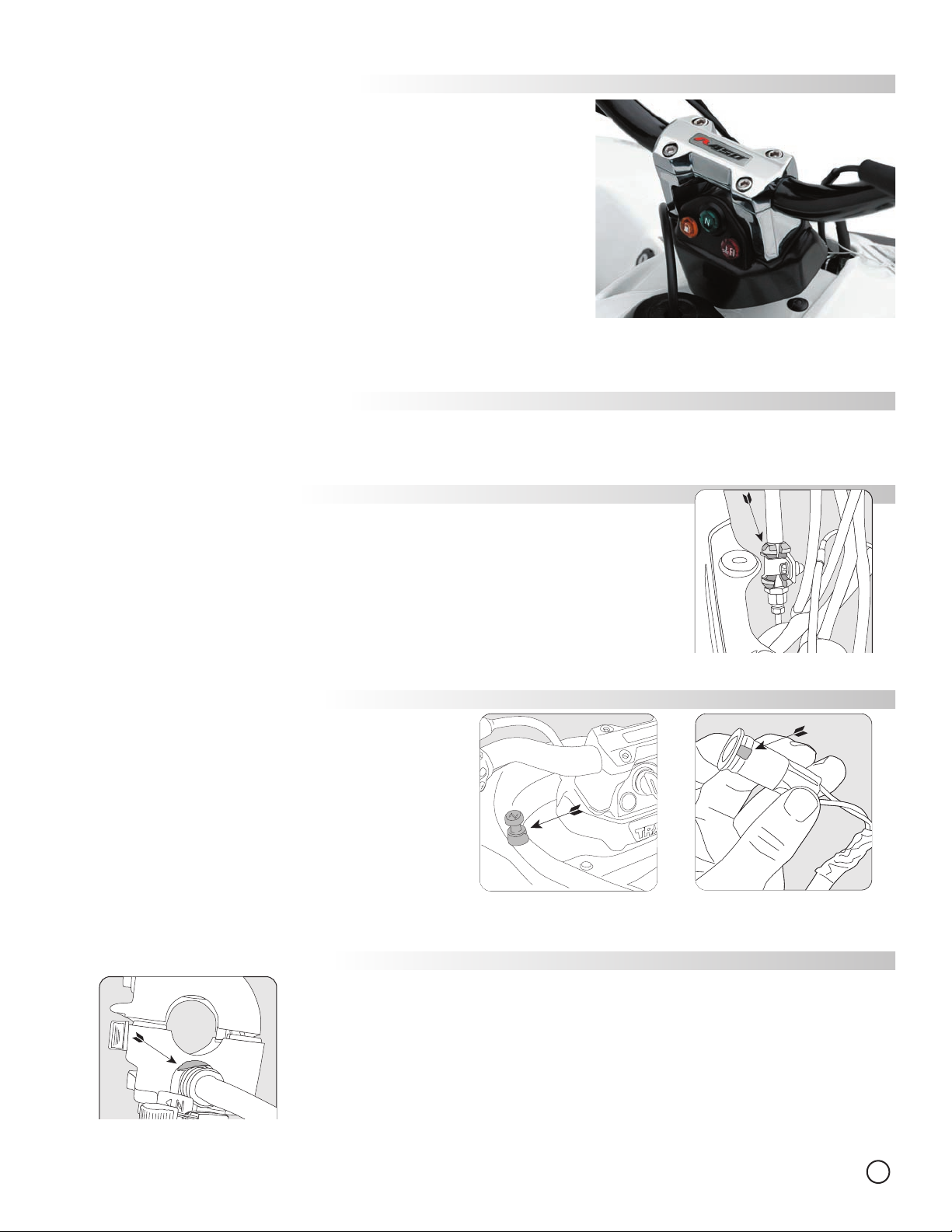
When installing the High Bend X-Bar:
The brake cable will be too tight without some adjustment. To get more slack in the cable, loosen the
bracket holding the cable under the front plastic nose piece. The cable can be moved further through
the bracket, though it may be necessary to cut the protective sheath first, as shown to the right.
HONDA 250 / 300 / 400EX ‘01-05 INSTALLS:
To Install Bar Clamp & Cover:
1. Remove stock handlebar and clamp.
2. Break off front brake line clip.
3. Take left plastic side panel off.*
Use a screwdriver to gently lift heads up off all 5 clips.
4. Unscrew choke clip from carburator
(located on left side of carburator, under the seat)
and remove choke cable from bike.*
5. Drill 1/2” hole in hood plastic.*
See drawing for choke cable mounting location.
6. Install choke cable in drilled hole and reconnect to carburator.*
7. Trim indicator rubber boots - take notch off.
See drawing for boot trim location.
8. Install indicator lights and key switch into cover.
9. Install cover, clamp and bars normally.
CHOKE CABLE DRILL
AND MOUNT LOCATION*
*Not all models require choke relocation
KAWASAKI KFX700 INSTALLS:
Trail Tech KFX700 bar clamp and dashboard parts are designed to mount directly on top of the stock lower
perches, which are welded to the steering stem.
DO NOT REMOVE THE LOWER PERCHES.
The KFX700 choke assembly must be trimmed so everything will fit on the bars.
trimming location.
TRX450 PROTECTIVE SHEATH
SLICE LOCATION
INDICATOR BOOT
TRIM LOCATION
See picture to left for
KFX700 CHOKE ASSEMBLY
TRIM LOCATION
The KFX700 has two locating holes in the stock bars to hold assemblies in place. Follow instructions on
page 1 for assistance with making locating holes in new X-Bars.
2
 Loading...