

GPS EXTERNAL ANTENNA
INSTALLATION GUIDE
Description:
• Trail Tech’s external GPS antenna is designed for use on
powersports vehicles, when the mounting location of the GPS device
prevents proper signal reception.
• The external antenna is tuned for mounting to plastic body panels.
Installation Tips/Notes:
• Mounting on or near metal surfaces will decrease signal strength.
• The “Trail Tech” logo should face towards the sky, and have a clear
view.
• Clean the mounting surface before application, and be sure any
residue from the cleaning agent has been removed.
• Route cable to the GPS device, taking care not to pinch or kink the
cable.
• Do not route the cable in such a manner that the cable will be
damaged by vehicle vibration or movement. (Fig. 5A)
• Screw the connector on to the external antenna port of your GPS
device.
Note: The connector should be hand tightened only, do not torque
the nut!
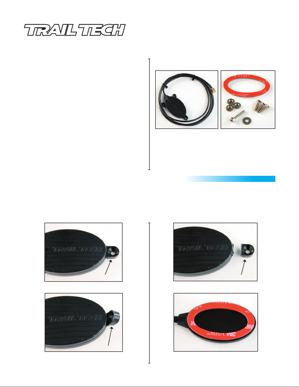
ANTENNA KIT CONTENTS:
EXTERNAL ANTENNA (9000-EEA)
Voyager External Antenna
010-ELV-118
Tech Support: 360-687-4530
tech_support@trailtech.net
9000-EAPK
ANTENNA INSTALLATION OPTION 1 (VHB ADHESIVE PAD):
Step 1. Locate the three mounting tabs on the outside of the antenna body. (Fig.1)
Step 2. Bend each tab upward to weaken the seem between the housing and mounting tab. (Fig. 2)
Step 3. Pull the tab downward to break away from the body of the antenna. (Fig. 3)
Step 4. Locate the provided VHB adhesive pad (9000-EAPK), & apply to the bottom of the antenna body. (Fig. 4)
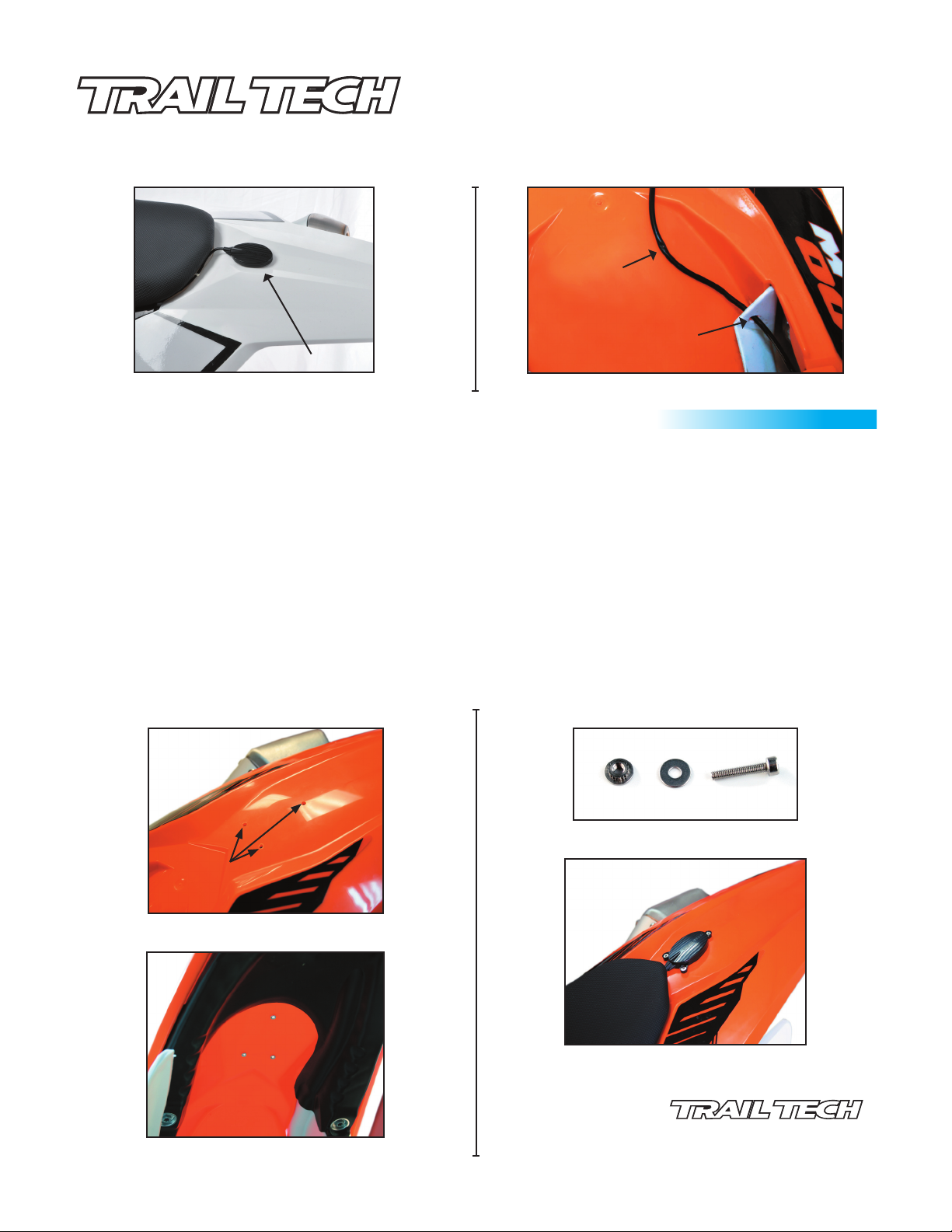
Step 5. Clean the mounting surface on the vehicle, peel the protective tape off the VHB pad & apply to intended mounting location. (Fig. 5)
Step 1.
Fig. 1
Mounting Tab
Step 3.
Fig. 2
Fig. 3
Break Tab Off
Fig. 4
Step 2.
Bend Upward
Apply VHB
Step 4.
GPS EXTERNAL ANTENNA
INSTALLATION GUIDE
Voyager External Antenna
010-ELV-118
Tech Support: 360-687-4530
tech_support@trailtech.net
Fig. 5
Antenna Installed
Step 5.
Fig. 5A
Antenna Wire
Pinched by Seat
Properly Routed to
Avoid Pinching
Watch for Bound or Pinched Antenna Wire
ANTENNA INSTALLATION OPTION 2 (BOLT ON INSTALLATION):
Step 1. Establish desired mounting location.
Step 2. Mark location of three mounting tabs on desired mounting location.
Step 3. Using a 3/16” drill bit, drill all three marked hole locations. (Fig. 6)
Step 4. Locate M3 x 20mm SCHS screw and M3 fender washer. (Fig. 7)
Step 5. Insert the self clinching nut, teeth up, into the under side of the mounting location. (Fig. 8)
Step 6. Place M3 fender washer on top of mounting location & insert M3x20SCHS into nut.
Step 7. Tighten the M3x20mm SCHS down until self clinching nut is firmly seated flush into the under side of mounting location. Repeat until all
three nuts are seated into mounting location.
Step 8. Discard M3x20mm SCHS & M3 fender washer. Note: These are for installation of self clinching nuts only & will not be used in final
installation.
Step 9. Locate three M3x12mm FHPS screws (9000-EAPK) and use for final mounting of antenna body by tightening them into self clinching nuts.
Note: Do not over tighten M3x12 FHPS. over tightening can strip the self clinching nuts out of the mounting location. Take care not to
push the self clinching nuts out of the mounting location. The self clinching nuts only hold force in the upward direction and can be
pushed out easily!
Fig. 6
Drill Mounting Holes
Mounting Holes Drilled
Fig. 8
Self Clinching Nuts Installed
Fig. 7
M3x20mm SCHS & M3 Washer
Fig. 9
Final Installation
MADE IN AMERICA
Trail Tech and Voyager are trademarks of Trail Tech, Inc.
 Loading...