

Page 1
D. Install the Barrel Tenon (slope facing towards the
muzzle) in the dovetail slot located underneath the
Barrel. Tap the Tenon into the dovetail cut-out using
a small mallet or similar tool.
Note: Barrel Tenon should fit snugly. If the fit is too tight,
sparingly file the dovetail portion of the Tenon with a triangular file to reduce it slightly. If the Tenon is too loose, using
a hammer and a punch, indent the surface at the base of the
dovetail with the punch so as to raise the edges around the
punch indentations. An additional method of tightening is
to install the Tenon and tap the angular edges of the dovetail with a hammer and punch so as to capture the Tenon.
Note: It will be necessary to remove the Tenon in order to
completely coat the dovetail and Tenon surfaces with blueing or browning solutions. Final fitting will happen after
coloring.
E. Using the two Rear Sight Screws, attach the Rear
Sight Base (incline sloping upward towards muzzle)
to the corresponding screw holes on top of the Barrel.
F. Install the Front Sight into the dovetail cut-out on
the top front of the Barrel using the same installation technique as with the Barrel Tenon.
Note: As with the Barrel Tenon, final fitting of sights
should be done only after blueing or browning the Barrel.
IV Lock Assembly
A. Insert the Lock into its cut-out in the side of the Stock.
B. Position the Ramrod Retaining Spring into the Stock
so that the end of the Spring which has the loophole is positioned towards the muzzle and the curve
is downwards towards the ramrod channel.
C. Install the Front Lock Plate Screw and Washer
through the hole in the Stock, passing it through the
loop-hole in the Ramrod Retaining Spring and into
its corresponding hole in the Lock Plate.
D. Install the second Lock Plate Screw and Washer.
Note: If holes are not perfectly aligned, enlarge one or both
Stock holes with a round file or drill to permit alignment.
Screws should be flush with the Lock Plate. File off any
portion of the Screws that protrude outside of the Lock
Plate for a cleaner look and to insure that a screw does not
interfere with the hammer travel.
V Installation of Barrel Assembly and
Trigger Assembly into Stock
A. Test that the Tang Screw turns smoothly within its cor-
responding threaded hole in the trigger plate by turning it in and out several times to burnish the threads.
B. Test that the Trigger moves freely within the Trigger
Guard. If not, move it back and forth a few times to
free up any binding. Pushing the trigger sideways in
its housing will also help loosen its movement.
C. Test that the Wedge transverses from the right side
of the Stock and exits the cut out on the left side.
Sparingly remove any wood or metal necessary for
an unobstructed fit. Remove Wedge.
D. Place the Trigger Guard Assembly into its inlet in
the Stock. Sparingly remove wood only if necessary
for a close fit. Ensure that the top bar of the Trigger
does not touch any wood.
E. Set Hammer in the half-cock position. Place the
Barrel, with Tang attached to the breech hook, into
the Stock. The Barrel Bolster should be positioned
concentrically into its cut-out in the Lock Plate and
the Lock Plate should be snug against the Barrel.
F. Insert the Tang Screw through the screw hole in the
Tang and pass it through the Stock and into its corresponding hole in the Trigger Assembly. Do not
tighten at this time.
Note: In the event the Tang Screw does not align properly,
enlarge the hole in the Stock with a round file or drill.
G. Install the Wedge through right side of Stock, engaging
the Barrel Tenon and exiting the left side of Stock.
Note: The wedge opening in the Stock can be slightly
enlarged if necessary. If the Stock Plates interfere, enlarge
opening with a file to permit unobstructed passage of the
Wedge. Take care not to bend the Wedge Plates.
H. Tighten Tang Screw securely.
Note: At this point, the Wedge should fit very snugly. Bend
the Wedge for a tighter fit. Flatten it for a looser fit. Be sure
to always install the Wedge from the right side and always
position the top of the bend facing upward.
I. At this point the Hammer should be positioned so
that it will fall squarely onto the Nipple. If it does
not, one or more of the following steps may be taken:
1. Remove wood from bottom of Lock recess,
until Lock is flush with the Barrel.
2. Remove wood as needed from under and
behind the barrel channel, including Tang area.
3. Check that the Lock Plate and Lock Plate
Screws are snugly fitted into the Stock and the
Lock is properly positioned in its cut-out.
4. If proper alignment is not obtained with the
previous steps, the Hammer may be bent
slightly by removing it from the Lock, heating
it and by bending it carefully to obtain the
correct alignment.
WARNING: NEVER attempt to change the position of the
barrel bolster in the Barrel. To rotate it from its original
position will impare ignition and could create a DANGEROUS situation with the potential of death or serious
bodily injury resulting as well as voiding the warranty.
CAUTION: With the Lock, Barrel and Trigger Assemby
installed and all Screws tightened, the hammer should
remain securely in its half-cock position and the pulling of
the trigger should not cause the hammer to fall. The hammer should also remain in the full-cock position until the
trigger is firmly pulled. If the Lock and trigger do not function properly in both positions, remove the Lock and make
the following adjustments:
1. Remove only as much wood as necessary inside the
lock plate recess to eliminate any binding of the
moving parts of the Lock.
2. Heat the protruding dowel like sear arm, located on
the inside of the Lock. Using vise grips or pliers,
slightly bend it up or down as necessary for better
contact with the top of the trigger.
3. If Sear and trigger are too close to each other, it is
also acceptable to file the top flat portion of the trigger that contacts the Sear to gain clearance.
VI Final Finishing of Wood and Metal
Note: This is where diligence pays off, proceed slowly and
be critical of your work and you will be rewarded with a
fine looking firearm.
A. Using progressively finer wood rasp and sandpa-
per, bring wood and metal surfaces flush with each
other. File and sand adjoining surfaces of different
components together to achieve a smooth transition
between surfaces. Proceed carefully, deliberately
and slowly.
B. Remove or tape over metal parts before staining or
finishing the Stock.
C. Polish bare steel parts with varying grits of emery
cloth, each one finer than the previous. Finish with
fine steel wool.
D. Brown or blue steel parts with chemicals available
in most gun shops.
899-56108I
5
6
7
FIT2
IMPORTANT!
Thoroughly read, understand and be
willing to follow the instructions and
warnings in this manual befor
e loading or
firing your new Traditions
TM
Muzzleloader.
Engineered For
Today’s Shooter
D
EERHUNTER
TM
R
IFLE
K
IT
A
SSEMBLY
I
NSTRUCTIONS
P.O. Box 776
• Old Saybrook, CT 06475-0776
www.traditionsfirearms.com
Tel: 860-388-4656
Fax: 860-388-4657
Page 2
Assembly Instructions
You should be aware that you are about to build a
muzzleloader which will be fully shootable. For this
reason it must be handled with the same precautions
and respect due any firearm. Before loading or shooting this gun, read and understand and always be willing to follow the instructions, loads and precautions
as outlined in the enclosed Warranty and Shooting
Instructions Booklet. If this booklet is not with your
kit, ask your dealer or contact TRADITIONS for a
free copy.
The following instructions will enable a moderately
handy person to build a safe, serviceable and
shootable muzzleloader. Greater skills and patience
will be rewarded with a truly fine rifle reminiscent of
the muzzleloading era.
Before beginning the actual assembly of the parts,
read these instructions while at the same time take
inventory of each part and develop an understanding
where each part goes and how they relate to each
other.
Next, begin initial assembly. Progressively improve
the fit of the various parts as each part is fitted to
another. Realize that after all parts have been installed
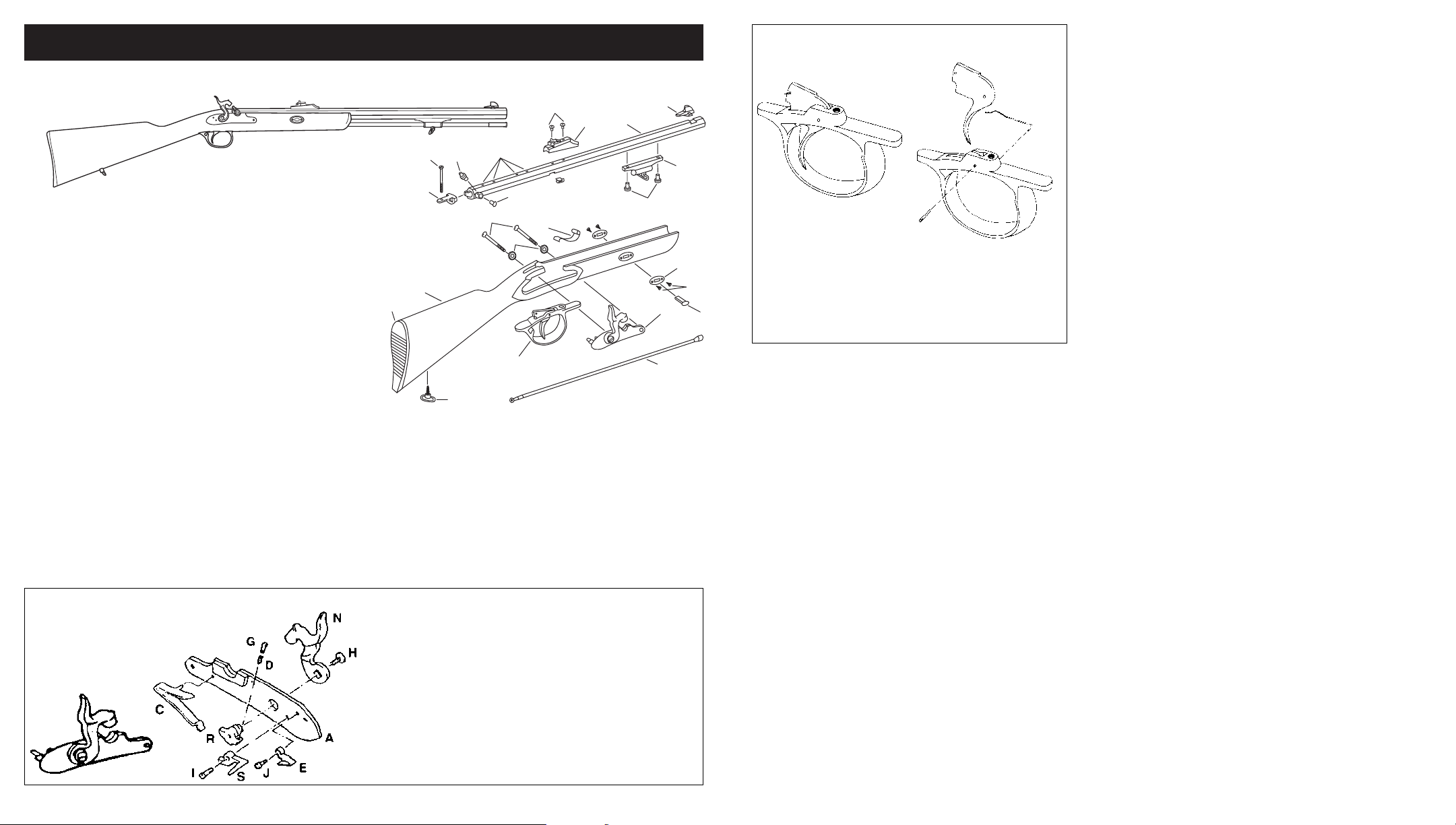
KR56108 .50 caliber percussion, drilled/tapped • KR56148 .54 caliber percussion, drilled/tapped
S
N
O
J
M
R
I
U
V
Q
AA
K
W
F
C
B
A
P
F
E
L
G
D
E
T
H
Letter Description
A Lock - Percussion 22203
B Lock Plate Washer (2) 22819
C Lock Plate Screw (2) 20620
D Stock Assembly K36001
(includes rubber buttpad, stock
plates & screws): unfinished
kit stock
E Stock Plate (2) 36016
F Stock Plate Screw (4) 36017
G Stock Sling Swivel 25046
H Rubber Butt Pad (2) 25026
I Barrel Assembly
(unblued, 24”):*
.50 cal. Percussion (1:48”) C361080
drilled/tapped
.54 cal. Percussion (1:48”) C361048
drilled/tapped
J Barrel Tang 20606
K Barrel Tenon 20533
L Barrel Wedge 22218
M Bolster Screw (perc. only) 20605
N Tang Screw 20841
O Nipple (percussion only) 20608
P Trigger/Trigger Guard Assembly 36022
Q Rear Adj. Sight 36810
R Front Sight 36611
S Ramrod Assembly (synthetic) 36028M
T Ramrod Spring 20621
DEERHUNTER RIFLE KIT
2
3
at that time, a more precise final fitting of all the parts
collectively will enable you to more precisely mate
them together. Do not attempt to totally fit and finish
each part as you install it on your gun. You will realize a finer result if you repeatedly and progressively
blend the parts together. This will improve the final
wood to metal fit and finish. Only after you have completed the final assembly, should you then file, sand,
stain and color the parts of the gun.
I General Assembly Instructions
A. Fitting: All metal parts should be placed into their
respective cut-outs of the Stock and fit snugly.
Remove wood sparingly and only as needed with a
sharp chisel or carving tool. Proceed slowly.
B. Wood Screws: To facilitate assembly and to avoid
cracking the Stock, mark and drill small pilot holes
into wood before inserting Wood Screws.
C. Metal Screws: Turn Screws into and out of their
threaded holes several times to burnish the threads
to insure smooth fit.
II Stock Assembly
A. Installation of Sling Swivel to underside of Butt Stock.
1. Measure and mark a point 4
1
⁄
2” forward of the butt
pad along the underside of the butt stock.
2. Select a drill bit slightly smaller than the screw
portion of the Sling Swivel.
3. Drill a pilot hole at the mark to a depth adquate to
accommodate the Screw portion of the Sling Swivel.
4. Install Sling Swivel into butt stock.
B. Installation of Wedge Plates to fore stock.
1. Position Wedge Plates into their factory pre-cut
recesses on each side of the fore stock.
2. Mark and drill pilot holes for each Wedge Plate
using a drill bit which is slightly smaller than the
Screws.
3. Install Wedge Plates with the Wedge Plate Screws.
III Barrel Assembly
A. Install the Ramrod Thimble/Rib Sling Swivel
Assembly to the underside of the Barrel with the
two Thimble/Barrel Rib Screws.
B. Install the Tang onto the hook of the breech of the
Barrel (rear). File the Tang or breech hook surfaces
sparingly and only if needed to obtain a smooth,
flush yet snug fit. Note: These two parts should
require a moderate amount of force to join them
together.
C. Install the Nipple and the Bolster Clean-out Screw
into the barrel bolster. Note: Coat the threads of
each with a lube for easy future removal.
4
Lock Assembly Parts
Percussion Lock Assembly
No. 22203
Letter Description Number
A Trigger Guard/
Trigger Plate 36023
B Trigger Spring 36043
C Trigger 60402-Z
D Trigger Pin 60609
Letter Description
1
*Barrel sold as an assembly; drum (in percussion model)
not sold separately.
Features and parts subject to change without notice.
Letter Description Number
A Lock Plate 90201
C Mainspring 70505
D Sear Adjusting Screw Spring 70520
E Sear Spring 70506
G Sear Adjusting Screw 70518
H Hammer Screw 75512
I Sear Screw 70514
J Sear Spring Screw 70121
N Hammer 70602
R Tumbler 70103
S Sear 70504
Trigger/Trigger Guard Assembly
Assembly No. 36022
C
B
A
D
Part Number
U Ramrod Thimble/Rib/
Swivel Assembly 36013
V Thimble/Rib Screw (2) 25014
W Scope Mount Hole Plug
Screw 8/40 (4) installed 26029
AA Front & Rear Mounting Screw (2) 50622
Part Number
 Loading...