

Tracker Maxima Duo, Maxima 1000/5, Maxima 2000/15, Maxima 5000/25 User Manual

Maxima Receiver

Notes

Congratulations! The Tracker Maxma Receiver System will provide you
with state of the art radio-location technology for hunting dogs, pets,
wildlife research, people tracking and law enforcement applications.
This User's Guide is intended to provide you with information on the
functions of the equipment as well as the basics of radio-location
techniques in order to get the most out of your system.
IMPORTANT:
READ ALL INSTRUCTIONS CAREFULLY before operating the receiver.
Warnings:
1. Never connect the unit to a power source (through external
power jack) without employing the Tracker External Power
Adapter (sold separately). Never connect the receiver to an AC
power source or reverse the polarization on a DC source.
2. Never operate the unit with a headset at high volume levels
3. Be careful to keep the receiver dry and minimize exposure to
rain, snow or other liquids.
4. Changes or modifications to this receiver, not approved by
Tracker Radio Systems, Inc. could void your authority to operate
this receiver under FCC regulations.
FCC ID: MWBFTV-466
T
his device complies with par
t 15 of the FCC rules. Operation is
subject to the following two conditions: 1) This device may not
cause harmful interference, and 2) this device must accept any
interference that may cause undesired operation.

Table of Contents:
Features 1
Receiver upgrades 2
Integrated Antenna 2
Operating the receiver 3
Controls 4
LCD (Liquid Crystal Display) 5
Turning ON and OFF 5
Selecting memory locations 6
Automatic/Manual Modes 6
Plug-ins 7
Headphone jack 8
External Power jack 8
Automatic Shut-off 8
External antenna 8
Programming 9
Adding a frequency 9
Changing a frequency 10
Deleting a frequency 11
Changing the batteries 11
Maintenance 12
Using your system 13
Getting Started 13
Effective Range 18
Obstacles 19
Signal bounce 19
Polarization 19
Overhead Utilities 20
Use in and around a vehicle 20
Location of Transmitter 20
Location of Receiver 21
Triangulation 21
Use of a Vehicle 23
Accessories 24
Troubleshooting 25
Specifications 29

Feature Summary:
• Fully synthesized receiver with programmable EEPROM memory
• Available in 4 Frequency ranges (150Mhz through 157Mhz,
164Mhz, 213Mhz through 223Mhz, and 433Mhz through 434Mhz).
• Fully programmable with up to 100 Memory locations
• Manual and Automatic gain control modes
• Large custom-designed Liquid Crystal Display (LCD)
• Microprocessor controlled functions, supervises synthesizer
• Backlit screen-with automatic light sensor to automatically activate
backlighting when required
• Low battery indicator
• Automatic shut-off
• External power jack (for use with optional 9 V adapter)
• Headphone jack
• Patented, virtually unbreakable antenna elements with 10 year
warranty incorporating steel hinges
• External antenna capable, either using bracket with external
antenna jack or upgrading receiver with external antenna jack (SMA)
•
Rugged body
, CNC milled from a solid aluminum bar and
powder coated
•
Splash proof design
1
Tracker Maxima Models:
Models
Number of Frequencies/channels
1 kHz steps
Memory locations
Duo 1000 2
1000/5 1000 5
2000/15 2000 15
5000/25 5000 25
Receiver upgrades:
Any Maxima receiver is upgradeable to monitor additional frequencies and memory locations (up to 100) by sending the unit to
Tracker. Charges are assessed for upgrading and shipping.
MAXIMA RECEIVER
The Tracker MAXIMA is a Directional Receiver for numerous
applications. The receiver is programmable within a frequency
range that matches the integrated antenna. The receiver body is
precision CNC milled from a solid aluminum bar and powder
coated. The antennas fold alongside the body of the receiver to
create the most easily transportable receiver/antenna combination available anywhere in the world.
Below is a review of the important features of the Maxima receiver.
Integrated Antenna:
A key feature of the Tracker Maxima receiver is the integrated folding antenna. Tracker antennas feature steel hinges connecting the
antenna elements to the receiver. You will notice that the antennas
are made of virtually unbreakable circuit board material. The
patented design allows the mechanical leng
th of the antenna to be
significantly shorter than the required electrical length.
2
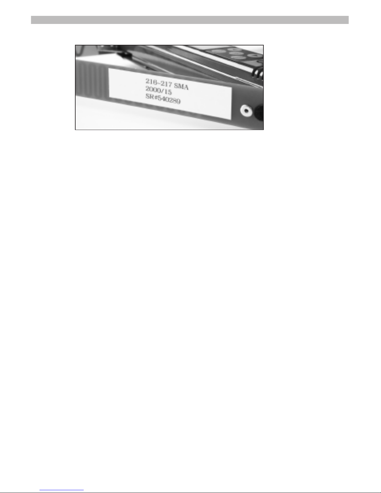
Base Frequency, model number and serial number are indicated on left rear antenna.
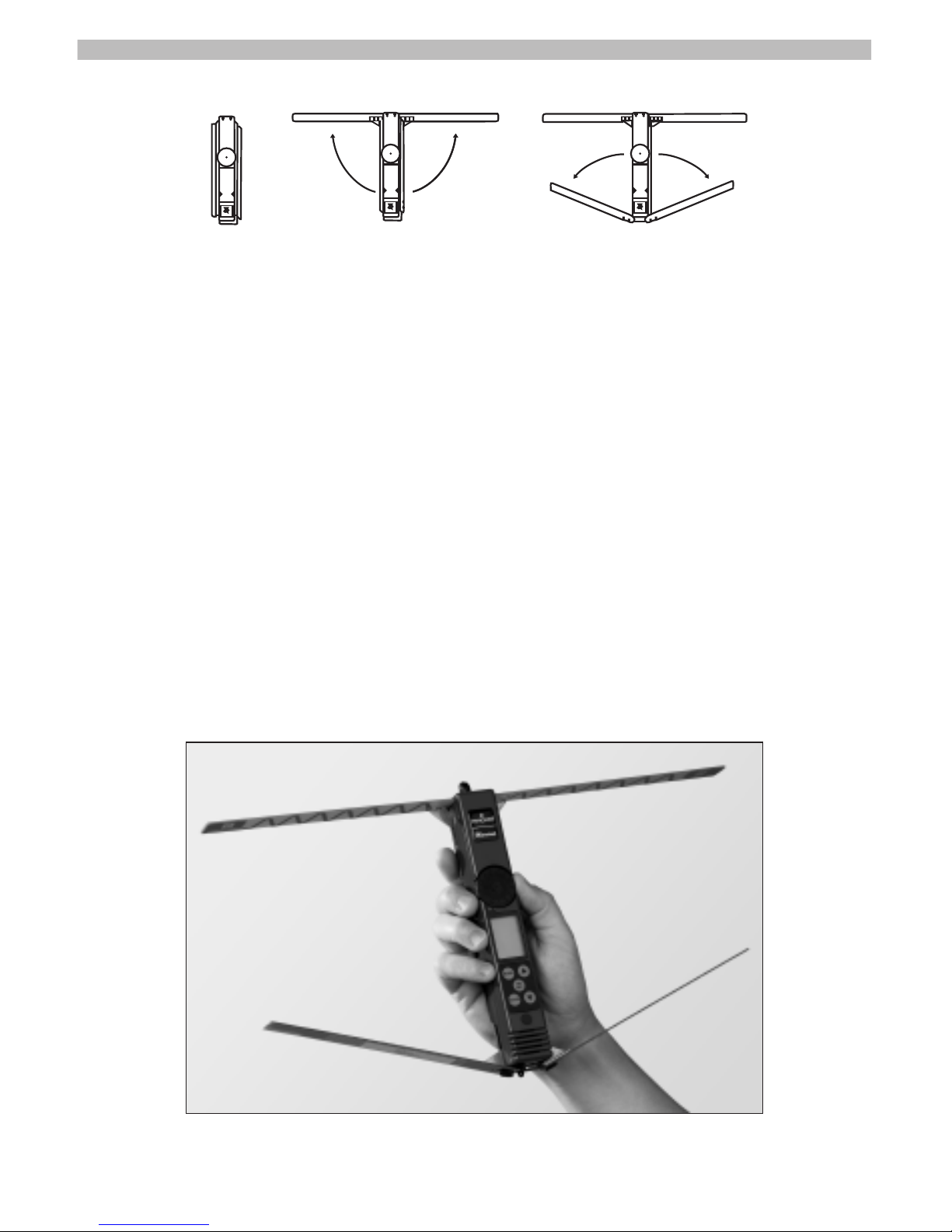
Operating the receiver:
To utilize the receiver, first unfold the antennas before activating
the receiver. The receiving antennas are located to the front of
the receiver and when fully extended are perpendicular to the
axis of the receiver. The reflecting antennas are located to the
back and when fully extended form a 75 degree angle to the
axis of the receiver. All four elements need to be extended
when tracking.
Grasp the receiver in one hand with your thumb close to the
gain wheel. For best results, be careful not to touch the antenna
as you track. In particular, do not allow the rear antennas to rest
on your wrist or forearm, as this can affect the bearing accuracy.
3
Correct way to hold Receiver
4
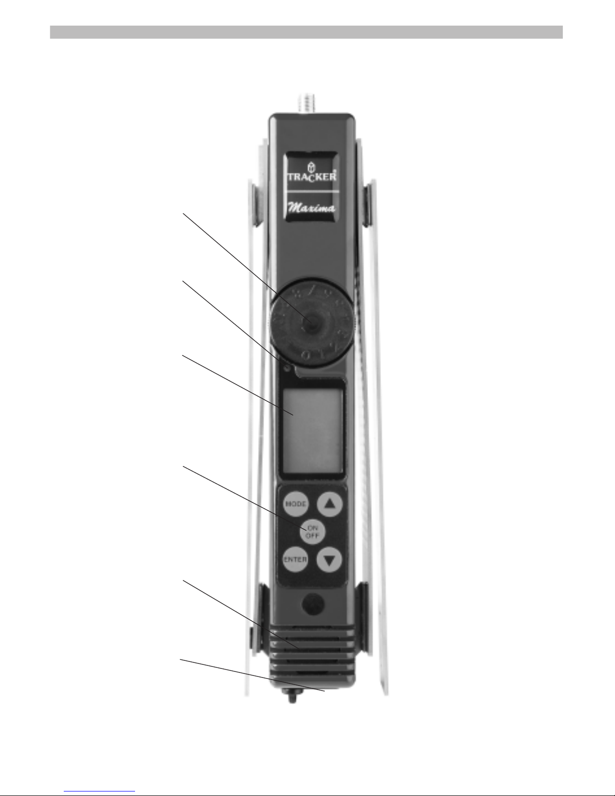
Gain Wheel
Light Sensor (for backlight)
LCD Screen
Operating Buttons
Speaker
Jacks
Controls:
front
back
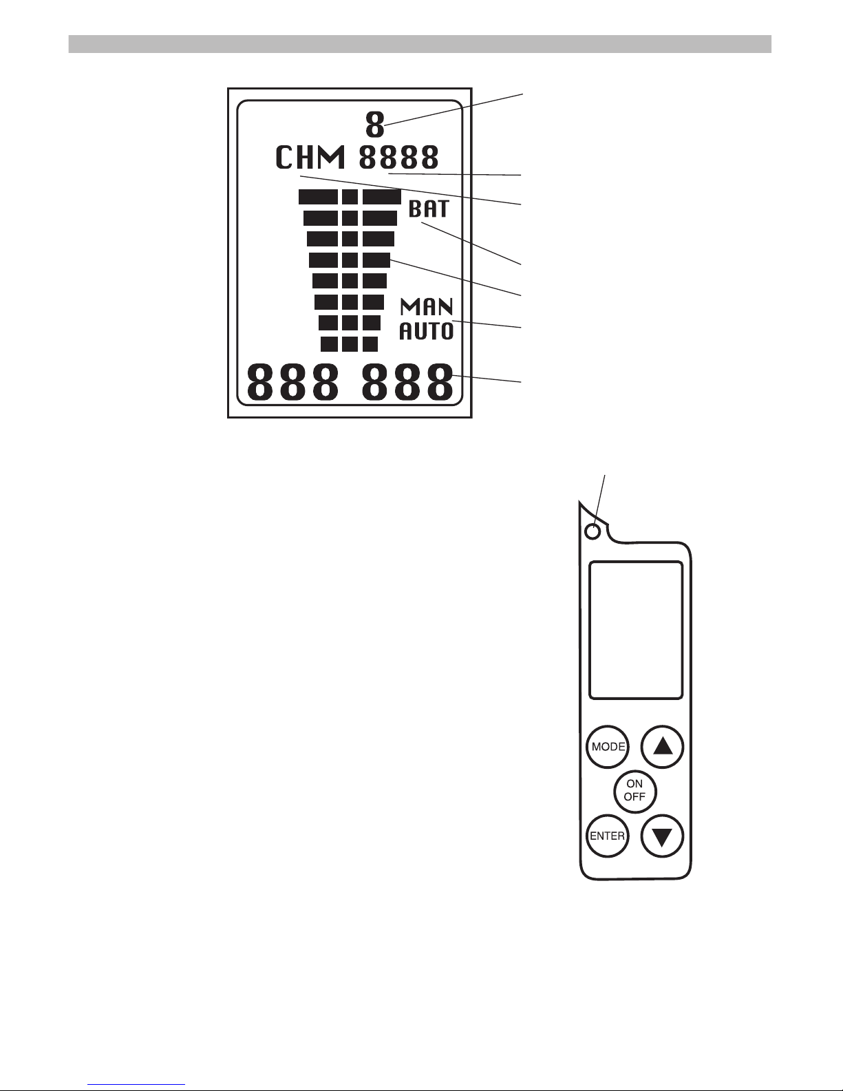
Operating the Maxima Receiver:
Turning the receiver ON:
Press and hold the ON/OFF switch for approximately 1- 2 seconds. On power up the receiver will perform a Self Test. The Backlight on the
Liquid Crystal Display (LCD) will illuminate for
one second and the display will appear as in
above illustration. Following self-test the unit
will be ready for use. Current settings (frequency, gain mode, gain setting) will be displayed.
Turning the receiver OFF:
Press and hold the ON/OFF switch for approximately 1 - 2 seconds. When the LCD displays
no information the unit is off.
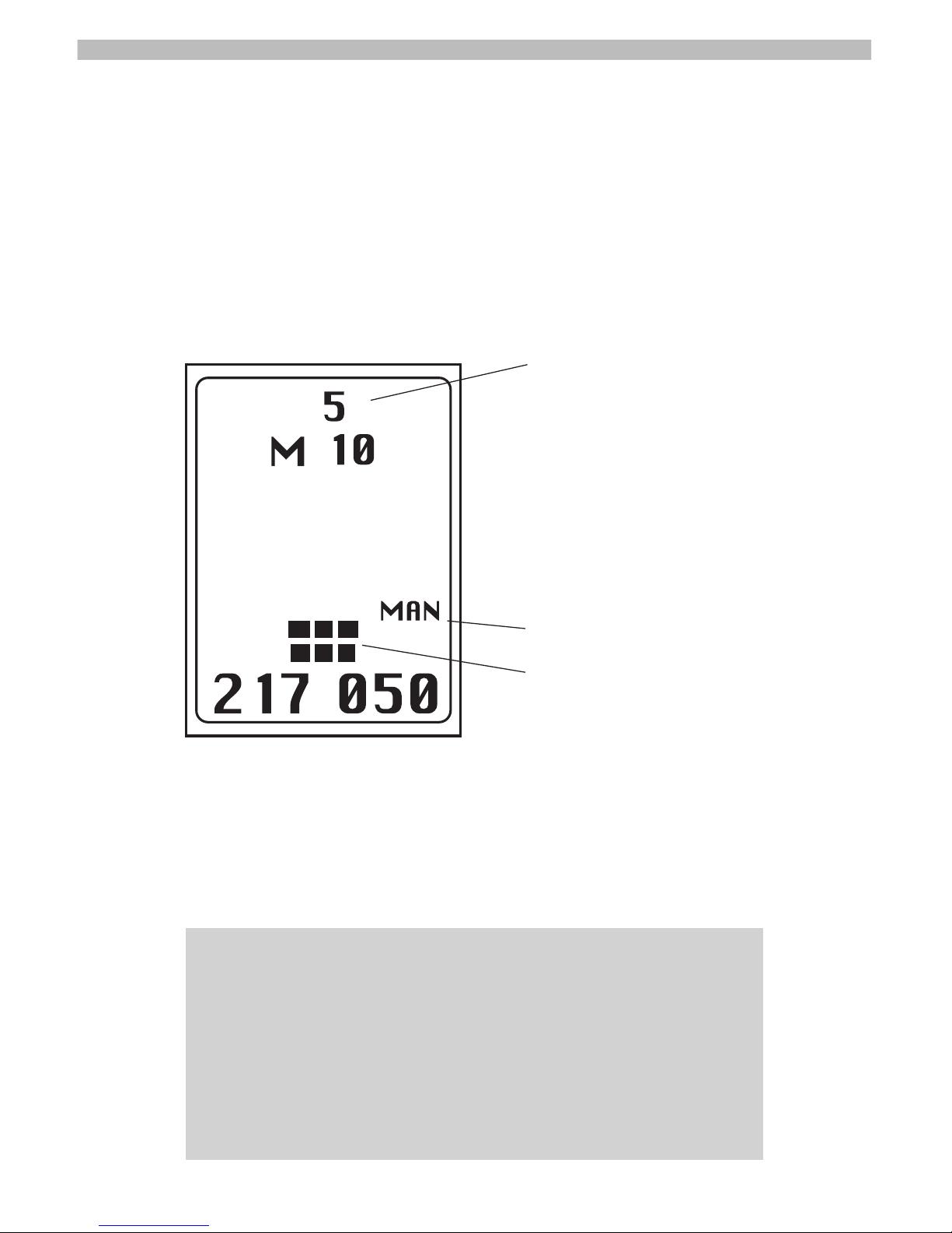
5
Gain Setting
Mode indication display, Memory/Channel
Channel editor and memory location
Low battery indicator
Signal strength bar graph
Manual/Automatic gain control mode
Current frequency
Light sensor to activate backlight.
Selecting Memory location:
Use the s and t buttons to move between Memory locations
that have programmed frequencies saved. The programmed
frequencies are displayed at the bottom of the Display. During
programming, use the
s button to change to a higher number
and the
t button change to a lower number.
Automatic/Manual Gain modes:
The gain should be set carefully in order to detect the transmitter
and to help in direction finding. A gain setting that is too high
will make it difficult to determine a bearing to the transmitter.
6
IMPORTANT NOTE: When the receiver is turned on, it will always
return to the last Memory location and Modes as when it was shut
off, i.e. M1, (automatic or manual) and gain level (in Manual). For
example, if you were monitoring 217.050 MHz frequency in Manual
mode at gain setting 8 when you turned the unit off, it will return to
217.050, Manual mode and gain setting 8 when turned on again, if
the Gain control Knob was not moved. Automatic Mode will always
have the gain go to maximum then adjust.
Gain Setting
Manual mode indicator
Optimum gain level for tracking
A unique feature of the Maxima receiver is the automatic gain
control mode. The “smart electronics” contained in the receiver
will automatically set the gain control based on the strength of
the signal. Note that automatic is good to help find a signal;
Manual is best for precise direction finding.
Manual mode allows the operator to set the gain level. Turn the
gain wheel to the lowest level where an audible beep is heard
and one or two bars are displayed on the LCD (see photo on
pg. 6). This will provide the most precise indication of bearing to
the transmitter.
Pressing the ENTER key when in memory selection mode, toggles receiver between Automatic and Manual gain control
modes. MAN or AUTO will indicate the current mode and displayed on the right side of the LCD screen. When in Automatic
mode, the AUTO will flash when adjusting gain. Current gain setting is displayed top center (0 through 9).
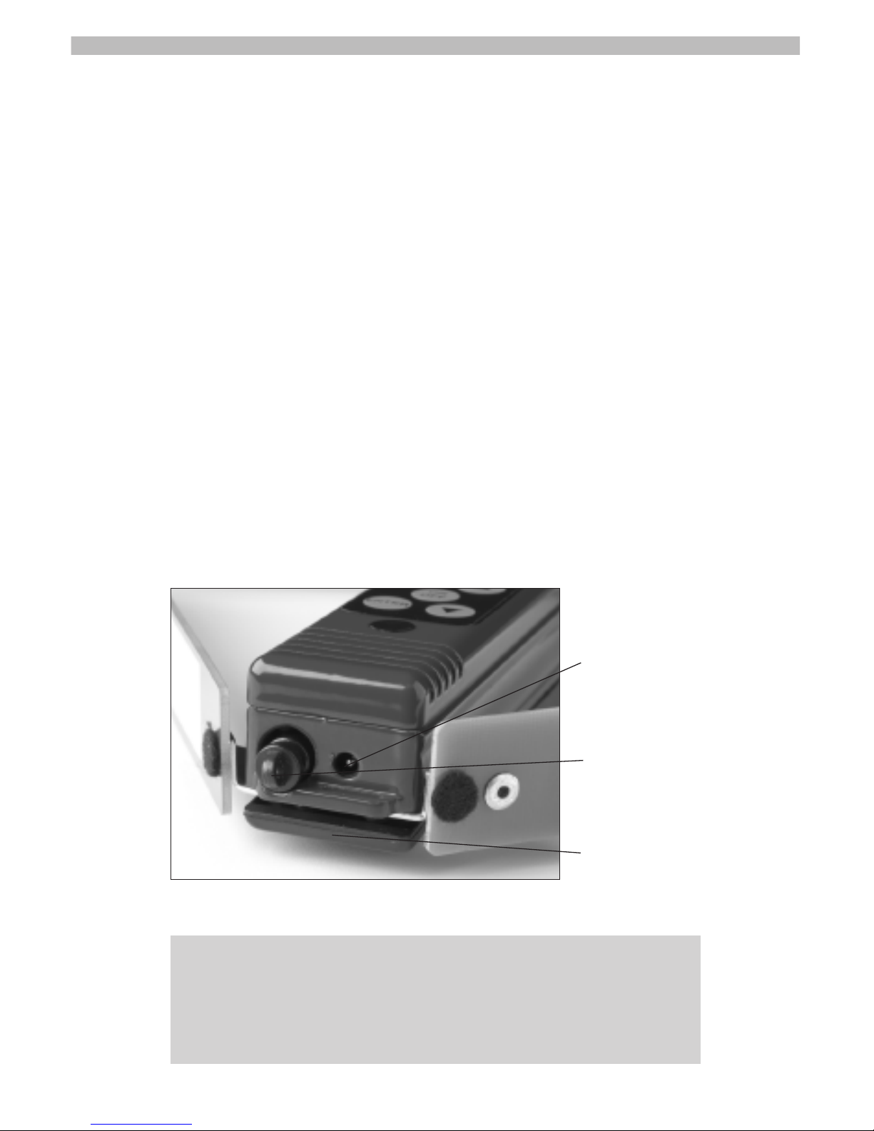
Plug ins:
7
IMPORTANT NOTE: Do not attach a ring or other attachment to
plastic plug for purposes of a safety strap. This may cause the
plug to break off requiring factory service. Use metal flange adjacent to the DC power jack to attach receiver to holster, belt, etc.
Sound cut-off/Headphone jack
External Power jack
Attachment flange
 Loading...