

Tracker BX811 User Manual

001B06ZXZ1A7
Hyper Box IP Camera
User’s Manual
Ver. 1.7
BX811

1
Table of Contents
1. Overview ................................................................................................................................ 2
1.1 Features ...................................................................................................................... 2
1.2 Package Contents ....................................................................................................... 3
1.3 Dimensions .................................................................................................................. 4
1.4 Connectors .................................................................................................................. 5
1.4.1 Light Sensor ................................................................................................. 6
2. Camera Cabling ..................................................................................................................... 6
2.1 Power Connection ....................................................................................................... 6
2.2 Ethernet Cable Connection .......................................................................................... 6
2.3 Lens Mounting ............................................................................................................. 7
2.4 Alarm I/O Connection .................................................................................................. 8
2.5 RS-485 Connection (DC12V/AC24V/PoE (RS-485) Models) ....................................... 8
3. System Requirements .......................................................................................................... 9
4. Access Camera ................................................................................................................... 10
5. Setup Video Resolution ...................................................................................................... 14
6. Configuration File Export / Import ..................................................................................... 15
7. Tech Support Information .................................................................................................. 16
7.1 Delete the Existing Viewer ......................................................................................... 16
7.2 Setup Internet Security .............................................................................................. 17
Appendix: Technical Specifications

2
1. Overview
Hyper Box IP Camera offers up to 4k2k resolution in real-time, providing
extraordinary images. With state-of-the-art encoding SOC, the camera is
capable of streaming 8MP resolution in real-time or 6MP resolution in real-time
+ 720P in real-time (or 2MP@120 fps). Multiple Region of Interest (ROI) and 3D
Noise Reduction are also supported for different application scenarios.
With all powerful functions mentioned above, the camera requires only
maximum 8.5W power consumption which saves a lot of expenses for users.
Hyper Box IP Camera is built-in with Auto Back Focus (ABF) function. Users
can simply adjust focus by clicking control buttons on the setting page, which
makes focus adjustment and remote focus tuning easier under 8MP resolution.
1.1 Features
8MP / 6MP / 4MP / 3MP Progressive Scan CMOS Sensor
Specific ARM for Analytics Hardware Acceleration
Quad Stream Compression- H.264 Baseline / Main / High Profile + MJPEG
Smart Event Function-
Motion Detection / N
etwork Failure Detection / Tampering Alarm / Periodical
Event / Manual Trigger / Audio Detection
Multiple and Dynamic Region of Interest (ROI) Windows
Auto Back Focus (ABF)*
3D Motion Compensated Noise Reduction (MCTF)
Text Overlay and Privacy Masks
microSD Card Support
BNC Analog Output
Triple Power Support- DC 12V / AC 24V / PoE
ONVIF Profile S Conformance
(*) Optional

3
1.2 Package Contents
Please check the package containing the following items listed below.
Hyper Box IP Camera
Power Switch Connector
CD
(bundled software and documentation)
Quick Guide
4
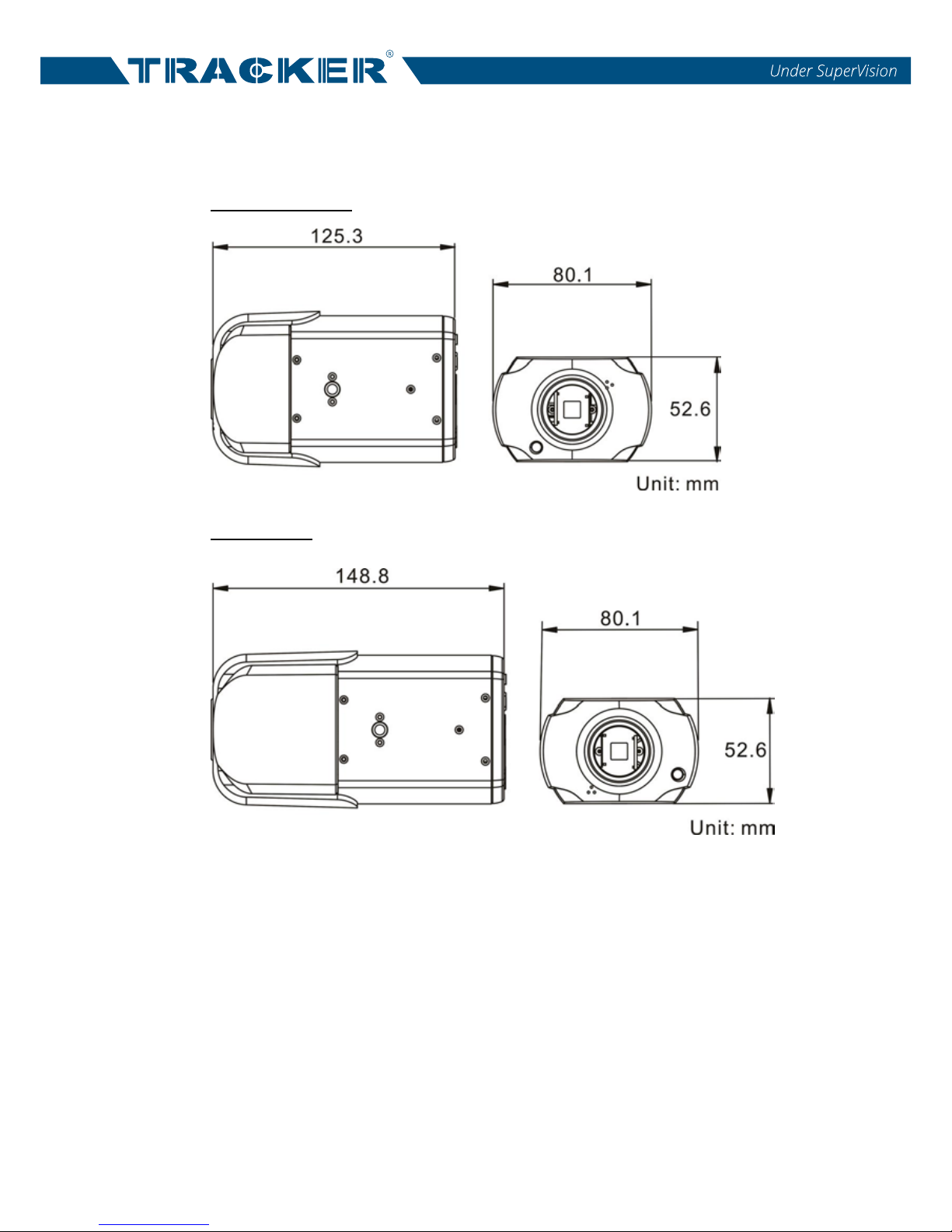
1.3 Dimensions
The dimensions of the camera are shown below.
Non-ABF Models
ABF Models
5
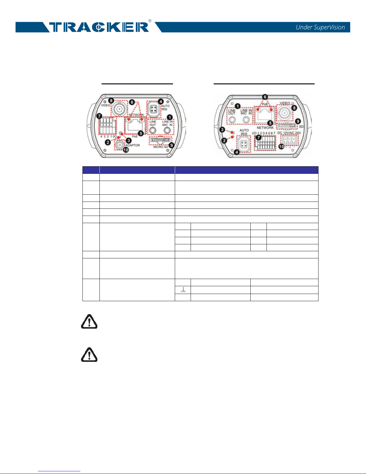
1.4 Connectors
The diagram below shows the various connectors of the camera. Definition for
each connector is given as follows.
DC 12V / AC 24V / PoE DC 12V / AC 24V / PoE (RS-485)
No.
Connector
Definition
1
Audio I/O
Two-way audio transmission
2 Default Button
Press the button with a proper tool for at least 20
seconds to restore the system.
3
Power LED
For power connection indication (green light)
4
Auto Iris
Auto iris lens connection
5
RJ-45
For network and PoE connections
6
Network LEDs
For network connection and activity indication
7 Alarm I/O
1
Alarm Out +
5
GND
2
Alarm Out –
6
D −
3
Alarm In +
7
D +
4
Alarm In –
8
BNC
For analog video output
9 microSD Card Slot
Insert the microSD card into the card slot to store
videos and snapshots. Do not remove the microSD
card when the camera is powered on.
10 Power (DC 12V / AC 24V)
+
DC 12V
AC 24V 1
1 2 3 4
I/O
DC
VIDEO
AC 24V
DC 12V
DC 12V Reserved
AC 24V GND
−
DC 12V GND
AC 24V 2
NOTE: If users are to use with AC 24V power adaptor, please first
connect the supplied power switch to the power connector.
NOTE: It is not recommended to record with the microSD card for 24/7
continuously, as it may not be able to support long term continuous data
read/write. Please contact the manufacturer of the microSD card for
information regarding the reliability and the life expectancy.
 Loading...