

Page 1
TL-ER6120
Gigabit Dual-WAN VPN Router
REV1.2.0
1910010936
Page 2

COPYRIGHT & TRADEMARKS
Specifications are subject to change without notice. is a registered trademark of
TP-LINK TECHNOLOGIES CO., LTD. Other brands and product names are trademarks of their
respective holders.
No part of the specifications may be reproduced in any form or by any means or used to make any
derivative such as translation, transformation, or adaptation without permission from TP-LINK
TECHNOLOGIES CO., LTD. Copyright © 2014 TP-LINK TECHNOLOGIES CO., LTD. All rights
reserved.
http://www.tp-link.com
FCC STATEMENT
This equipment has been tested and found to comply with the limits for a Class A digital device,
pursuant to part 15 of the FCC Rules. These limits are designed to provide reasonable protection
against harmful interference when the equipment is operated in a commercial environment. This
equipment generates, uses, and can radiate radio frequency energy and, if not installed and used in
accordance with the instruction manual, may cause harmful interference to radio communications.
Operation of this equipment in a residential area is likely to cause harmful interference in which case
the user will be required to correct the interference at his own expense.
This device complies with part 15 of the FCC Rules. Operation is subject to the following two
conditions:
1) This device may not cause harmful interference.
2) This device must accept any interference received, including interference that may cause
undesired operation.
Any changes or modifications not expressly approved by the party responsible for compliance could
void the user’s authority to operate the equipment.
CE Mark Warning
This is a class A product. In a domestic environment, this product may cause radio interference, in
which case the user may be required to take adequate measures.
-I-
Page 3

Продукт сертифіковано згідно с правилами системи УкрСЕПРО на відповідність вимогам
нормативних документів та вимогам, що передбачені чинними законодавчими актами України.
Safety Information
When product has power button, the power button is one of the way to shut off the product; When
there is no power button, the only way to completely shut off power is to disconnect the product or
the power adapter from the power source.
Don’t disassemble the product, or make repairs yourself. You run the risk of electric shock and
voiding the limited warranty. If you need service, please contact us.
Avoid water and wet locations.
安全諮詢及注意事項
●請使用原裝電源供應器或只能按照本產品注明的電源類型使用本產品。
●清潔本產品之前請先拔掉電源線。請勿使用液體、噴霧清潔劑或濕布進行清潔。
●注意防潮,請勿將水或其他液體潑灑到本產品上。
●插槽與開口供通風使用,以確保本產品的操作可靠並防止過熱,請勿堵塞或覆蓋開口。
●請勿將本產品置放於靠近熱源的地方。除非有正常的通風,否則不可放在密閉位置中。
●請不要私自打開機殼,不要嘗試自行維修本產品,請由授權的專業人士進行此項工作。
此為甲類資訊技術設備,于居住環境中使用時,可能會造成射頻擾動,在此種情況下,使用者會被要求
採取某些適當的對策。
This product can be used in the following countries:
AT BG BY CA CZ DE DK EE
ES FI FR GB GR HU IE IT
LT LV MT NL NO PL PT RO
RU SE SK TR UA
-II-
Page 4

CONTENTS
Package Contents..................................................................................................................1
Chapter 1 About this Guide
1.1 Intended Readers ..................................................................................................................2
1.2 Conventions ...........................................................................................................................2
1.3 Overview of this Guide...........................................................................................................2
Chapter 2 Introduction
2.1 Overview of the Router ..........................................................................................................4
2.2 Features.................................................................................................................................5
2.3 Appearance............................................................................................................................6
2.3.1 Front Panel ................................................................................................................6
2.3.2 Rear Panel.................................................................................................................7
Chapter 3 Configuration
3.1 Network..................................................................................................................................9
...................................................................................................2
..........................................................................................................4
........................................................................................................9
3.1.1 Status.........................................................................................................................9
3.1.2 System Mode.............................................................................................................9
3.1.3 WAN ........................................................................................................................12
3.1.4 LAN..........................................................................................................................28
3.1.5 DMZ.........................................................................................................................31
3.1.6 MAC Address...........................................................................................................33
3.1.7 Switch ......................................................................................................................34
3.2 User Group ..........................................................................................................................41
3.2.1 Group.......................................................................................................................41
3.2.2 User .........................................................................................................................42
3.2.3 View.........................................................................................................................42
3.3 Advanced .............................................................................................................................44
3.3.1 NAT..........................................................................................................................44
3.3.2 Traffic Control ..........................................................................................................52
-III-
Page 5

3.3.3 Session Limit ...........................................................................................................55
3.3.4 Load Balance...........................................................................................................57
3.3.5 Routing ....................................................................................................................61
3.4 Firewall.................................................................................................................................66
3.4.1 Anti ARP Spoofing ...................................................................................................66
3.4.2 Attack Defense ........................................................................................................69
3.4.3 MAC Filtering ...........................................................................................................71
3.4.4 Access Control.........................................................................................................71
3.4.5 App Control..............................................................................................................77
3.5 VPN......................................................................................................................................79
3.5.1 IKE...........................................................................................................................79
3.5.2 IPsec........................................................................................................................83
3.5.3 L2TP/PPTP..............................................................................................................90
3.6 Services ...............................................................................................................................94
3.6.1 PPPoE Server..........................................................................................................94
3.6.2 E-Bulletin ...............................................................................................................100
3.6.3 Dynamic DNS ........................................................................................................102
3.6.4 UPnP .....................................................................................................................108
3.7 Maintenance ......................................................................................................................109
3.7.1
3.7.2 Management..........................................................................................................112
3.7.3 License ..................................................................................................................114
3.7.4 Statistics................................................................................................................. 115
Admin Setup
..........................................................................................................109
3.7.5 Diagnostics ............................................................................................................ 117
3.7.6 Time....................................................................................................................... 119
3.7.7 Logs.......................................................................................................................122
Chapter 4 Application
4.1 Network Requirements.......................................................................................................124
........................................................................................................124
-IV-
Page 6

4.2 Network Topology...............................................................................................................125
4.3 Configurations....................................................................................................................125
4.3.1 Internet Setting ......................................................................................................125
4.3.2 VPN Setting ...........................................................................................................127
4.3.3 Network Management............................................................................................133
4.3.4 Network Security....................................................................................................137
Chapter 5 CLI
5.1 Configuration......................................................................................................................143
5.2 Interface Mode ...................................................................................................................146
5.3 Online Help ........................................................................................................................147
5.4 Command Introduction.......................................................................................................149
5.4.1 ip............................................................................................................................149
5.4.2 ip-mac....................................................................................................................149
5.4.3 sys .........................................................................................................................150
5.4.4 user........................................................................................................................151
5.4.5 history ....................................................................................................................152
5.4.6 exit .........................................................................................................................153
Appendix A Hardware Specifications
................................................................................................................143
...........................................................................154
Appendix B FAQ
Appendix C Glossary
.........................................................................................................155
..................................................................................................157
-V-
Page 7

Package Contents
The following items should be found in your package:
One TL-ER6120 Router
One Power Cord
One Console Cable
One Ground Cable
Two mounting brackets and other fittings
Installation Guide
Resource CD
Note:
Make sure that the package contains the above items. If any of the listed items is damaged or missing,
please contact with your distributor.
-1-
Page 8
Chapter 1 About this Guide
This User Guide contains information for setup and management of TL-ER6120 router. Please read
this guide carefully before operation.
1.1 Intended Readers
This Guide is intended for Network Engineer and Network Administrator.
1.2 Conventions
In this Guide the following conventions are used:
The router or TL-ER6120 mentioned in this Guide stands for TL-ER6120 SafeStream Gigabit
Dual-WAN VPN Router without any explanation.
Menu Name→Submenu Name→Tab page indicates the menu structure. Advanced→NAT
→Basic NAT means the Basic NAT page under the NAT menu option that is located under the
Advanced menu.
Bold font indicates a toolbar icon, menu or menu item.
<Font> indicate a button.
Symbols in this Guide:
Symbol Description
Ignoring this type of note might result in a malfunction or damage to the
Note:
Tips:
device.
This format indicates important information that helps you make better use of
your device.
1.3 Overview of this Guide
Chapter 1 About This Guide Introduces the guide structure and conventions.
Chapter 2 Introduction Introduces the features an
Chapter 3 Configurations Introduces how to configure the router via Web management page.
Chapter 4 Application Introduces the practical application of the router on the enterprise network.
Chapter5 CLI Introduces how to log in and set up the router using CLI commands by
console port.
d appearance of TL-ER6120 router.
-2-
Page 9

Appendix A Hardware
Lists the hardware specifications of this router.
Specifications
Appendix B FAQ Provides the possible solutions to the problems that may occur during the
installation and operation of the router.
Appendix C Glossary Lists the glossary used in this guide.
-3-
Page 10

Chapter 2 Introduction
Thanks for choosing the SafeStream Gigabit Dual-WAN VPN Router TL-ER6120.
2.1 Overview of the Router
The SafeStream Gigabit Dual-WAN VPN Router TL-ER6120 from TP-LINK possesses excellent data
processing capability and multiple powerful functions including IPsec/PPTP/L2TP VPN, Load Balance,
Access Control, Bandwidth Control, Session Limit, IM/P2P Blocking, PPPoE Server and so on, which
consumedly meet the needs of small and medium enterprise, hotels and communities with volumes of
users demanding a efficient and easy-to-manage network with high security.
Powerful Data Processing Capability
+ Built-in MIPS64 network processor and 128MB DDRII high-speed RAM allows the stability and
reliability for operation.
Virtual Private Network (VPN)
+ Providing comprehensive IPsec VPN with DES/3DES/AES encryptions, MD5/SHA1
identifications and automatically/manually IKE Pre-Share Key exchanges.
+ Supporting PPTP/L2TP VPN Server mode to allow the staff on business or remote branch office
to access the headquarter network.
Online Behavior Management
+ Complete Functions of Access Rules can allow managers to select the network service levels to
block or allow applications of FTP downloading, Email, Web browsing and so on.
+ Deploying One-Click restricting of IM/P2P applications to save time & energy while reserving
exceptional groups for certain users.
+ Supporting URL Filtering to prevent potential hazards from visiting the malicious Web sites.
Powerful Firewall
+ Supporting One-Click IP-MAC Binding to avoid ARP spoofing and guarantee a network without
stagnation.
+ Featured Attack Defense to protect the network from a variety of flood attack and packet
anomaly attack.
+ Possessing MAC Filtering function to block the access of illegal hosts.
Flexible Traffic Control
+ Featured Bandwidth Control with flexible bandwidth management to automatically control the
bandwidth of the host in bi-direction to avoid bandwidth over occupation, as well as optimize
bandwidth usage.
+ Supporting Session Limit to avoid the complaint of a few people to force whole sessions.
-4-
Page 11

Dual-WAN Ports
+ Providing two 10/100/1000M WAN ports for users to connect two Internet lines for bandwidth
expansion.
+ Supporting multiple Load Balance modes, including Bandwidth Based Balance Routing,
Application Optimized Routing, and Policy Routing to optimize bandwidth usage.
+ Featured Link Backup to switch all the new sessions from dropped line automatically to another
for keeping an always on-line network.
Easy-to-use
+ Providing easy-to-use GUI with clear configuration steps and detailed help information for the
users to configure the router simply.
+ Helping administrators to monitor the whole network status and take actions to malfunctions
according to the recorded log information.
+ Supporting remote management to manage the router from remote places.
2.2 Features
Hardware
2 gigabit WAN ports, 2 gigabit LAN ports, 1 gigabit LAN/DMZ port and 1 Console port
Built-in high-quality power supply with non-fun system design for quietness
Possesses standard-sized, 19-inch outfit for standard rack
Supports Professional 4kV common mode
Complies with IEEE 802.3, IEEE 802.3u, IEEE 802.3ab standards
Supports AH, ESP, IKE, PPP protocols
Supports TCP/IP, DHCP, ICMP, NAT, NAPT protocols
Supports PPPoE, SNTP, HTTP, DDNS, UPnP, NTP protocols
Basic Functions
Supports Static IP, Dynamic IP, PPPoE/Russian PPPoE, L2TP/Russian L2TP, PPTP/Russian
lightning protection
PPTP, Dual Access, BigPond Internet connections
Supports Virtual Server, Port Triggering, ALG, Static Route and RIP v1/v2
Built-in Switch supporting Port Mirror, Port VLAN, Rate Control and so on
Supports to change the MAC address of LAN, WAN, DMZ port
Supports Logs, Statistics, Time setting
Supports Remote and Web management
-5-
Page 12

Supports Diagnostic (Ping/Tracert) and Online Detection
VPN
Supports IPsec VPN and provides up to 100 IPsec VPN tunnels
Supports IPSec VPN in LAN-to-LAN or Client-to-LAN
Provides DES, 3DES, AES128, AES152, AES256 encryption, MD5, SHA1 authentication
Supports IKE Pre-Share Key and DH1/DH2/DH5 Key Exchanges
Supports PPTP/L2TP Server/Client
Traffic Control
Supports Bandwidth Control
Supports Session Limit
Security
Built-in firewall supporting URL/MAC Filtering
Supports Access Control
Supports Attack Defense
Supports IP-MAC Binding
Supports GARP (Gratuitous ARP)
Deploys One-Click restricting of IM/P2P applications
2.3 Appearance
2.3.1 Front Panel
The front panel of TL-ER6120 is shown as the following figure.
LEDs
LED
PWR
Status
On The router is powered on
Off The router is powered off or power supply is abnormal
Indication
-6-
Page 13

LED
SYS
Link/Act
Speed
DMZ
Status
Indication
Flashing The router works properly
ff On/O The router works improperly
On There is a device linked to the corresponding port
Off There is no device linked to the corresponding port
ceiving data Flashing The corresponding port is transmitting or re
On (Green) The linked device is running at 1000Mbps
On (Yellow) The linked device is running at 100Mbps
Off
There is no device linked to the corresponding port or the
linked device is running at 10Mbps
On The port is working in DMZ mode
The port is working in LAN mode Off
escription Interface D
Interface Port Description
WAN 1~2
LAN 1~3
The WAN port is for connecting the router to a DSL/Cable
modem or Ethernet by the RJ45 cable
The LAN port is for connecting the router to the local PCs or
switches by the RJ45 cable
DMZ 3 The DMZ port is for connecting the router to the servers
Console N/A
Reset button
The Console port is for connecting with the serial port of a
computer or terminal to monitor and configure the router
Use the button to restore the router to the factory defaults. With the router powered on, use a pin to
press and hold the Reset button (about 4~5 seconds). After the SYS LED goes out, release the Reset
button. If the SYS LED is
flashing with
a high frequency about two or three seconds, it means the router
is restored successfully.
2.3.2 Rear Panel
The rear panel of TL-ER6120 is shown as the follow
ing figure.
-7-
Page 14

Power Socket
Connect the female connector of the power cord to this power socket, and the male connector to the AC
power outlet. Please make sure the voltage of the power supply meets the requirement of the input
voltage (100-240V~ 50/60Hz).
Grounding Terminal
The router already comes with lightning protection mecha
nism. You can also ground the router through
the PE (Protecting Earth) cable of AC cord or with Ground Cable.
Note:
Please use only the power cord provided with this router.
-8-
Page 15
Chapter 3 Configuration
3.1 Network
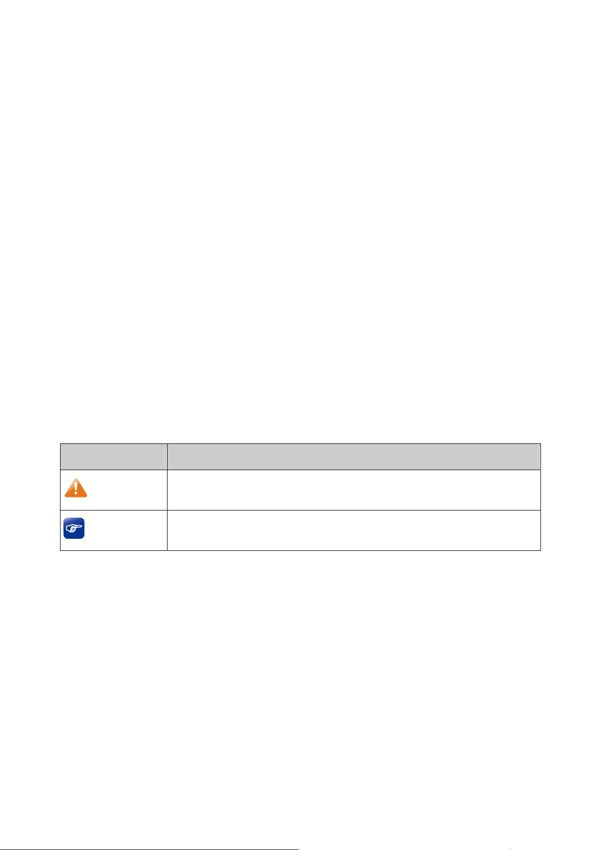
3.1.1 Status
The Status page shows the system information, the port connection status and other information
related to this router.
Choose the menu Network→Status to load the following page.
Figure 3-1 Status
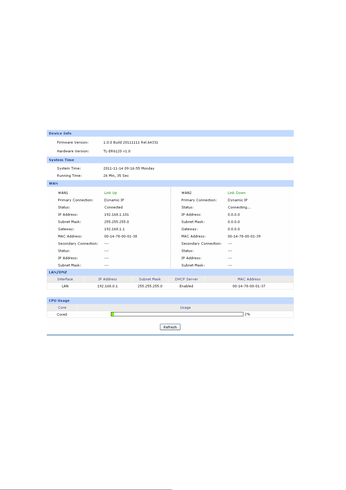
3.1.2 System Mode
The TL-ER6120 can work in three modes: NAT, Non-NAT and Classic.
If your router is hosting your local network’s connection to the Internet with a network topology as the
Figure 3-2 shown, you can set it to NAT mode.
-9-
Page 16
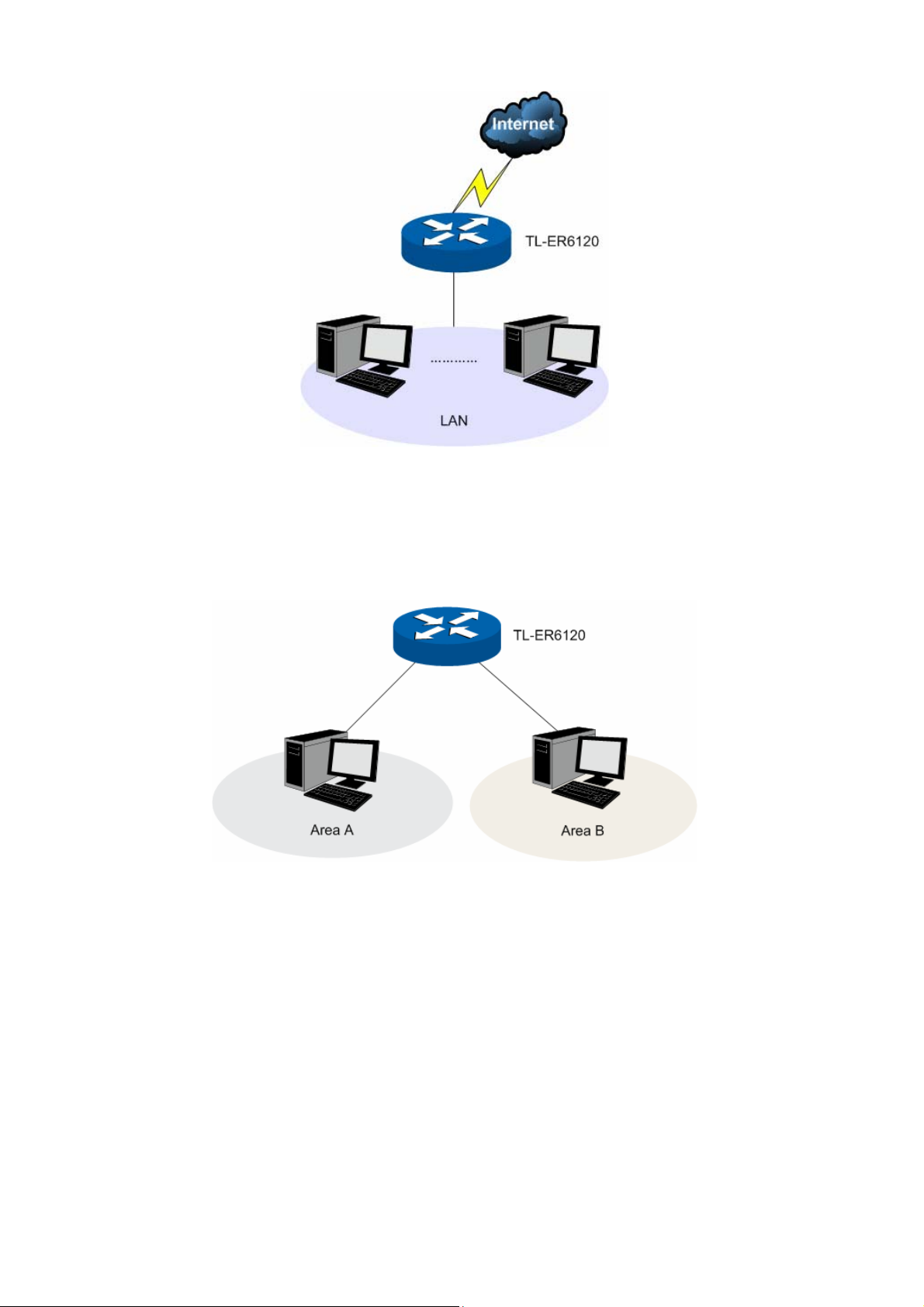
Figure 3-2 Network Topology - NAT Mode
If your router is connecting the two networks of different areas in a large network environment with a
network topology as the Figure 3-3 shown, and forwards the packets betwe
en these two networks by
the Routing rules, you can set it to Non-NAT mode.
Figure 3-3 Network Topology – Non-NAT Mode
If your router is connected in a combined network topology as the Figure 3-4 shown, you can set it to
Classic Mode.
-10-
Page 17
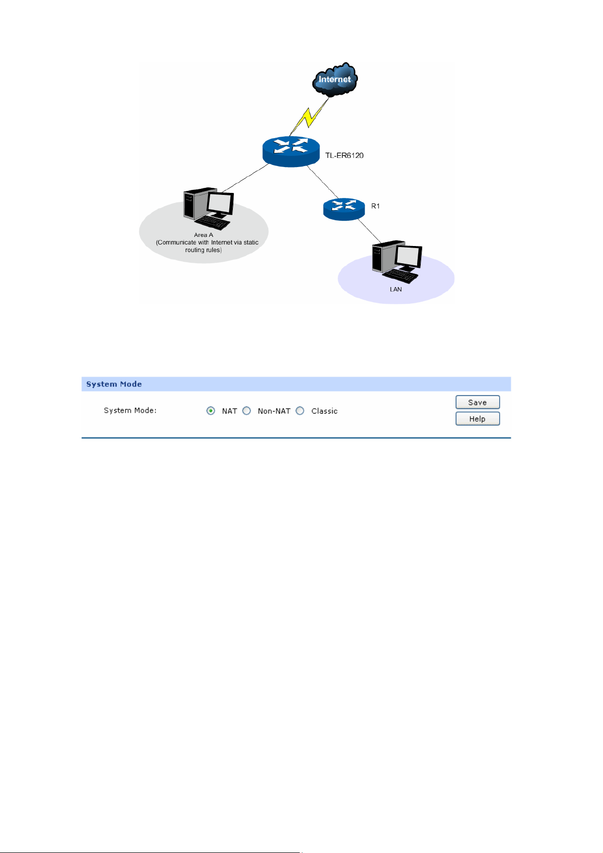
Figure 3-4 Network Topology – Classic Mode
Choose the menu Network→System Mode to load the following page.
Figure 3-5 System Mode
You can select a System Mode for your router according to your network need.
NAT Mode
NAT (Network Address Translation) mode allows the router to translate private IP addresses within
internal networks to public IP addresses for traffic transport over external networks, such as the
Internet. Incoming traffic is translated back for delivery within the internal network. However, the router
will drop all the packets whose source IP addresses are in different subnet of LAN port. For example: If
the LAN port of the router is set to 192.168.0.1 for IP address and 255.255.255.0 for the Subnet Mask,
then the subnet of LAN port is 192.168.0.0/24. The packet with 192.168.0.123 as its source IP address
can be transported by NAT, whereas the packet with 20.31.76.80 as its source IP address will be
dropped.
Non-NAT Mode
In this mode, the router functions as the traditional Gateway and forwards the packets via routing
protocol. The Hosts in different subnets can communicate with one another via the routing rules
whereas no NAT is employed. For example: If the DMZ port of the router is in WAN mode, the Hosts in
the subnet of DMZ port can access the servers in Internet only when the Static router rules permit.
-11-
Page 18
Note:
In Non-NAT mode, all the NAT forwarding rules will be disabled.
Classic Mode
It's the combined mode of NAT mode and Non-NAT mode. In Classic mode, the router will first
transport the packets which are compliant with NAT forwarding rules and then match the other packets
to the static routing rules. The matched packets will be transmitted based on the static routing rules
and the unmatched ones will be dropped. In this way, the router can implement NAT for the packets
without blocking the packets in the different subnet of the ports.
3.1.3 WAN
TL-ER6120 provides the following six Internet connection types: Static IP, Dynamic IP, PPPoE/Russian
PPPoE, L2TP/Russian L2TP, PPTP/Russian PPTP and BigPond. To configure the WAN, please first
select the type of Internet connection provided by your ISP (Internet Service Provider).
Tips:
It’s allowed to set the IP addresses of both the WAN ports within the same subnet. However, to
guarantee a normal communication, make sure that the WAN ports can access the same network,
such as Internet or a local area network.
Choose the menu Network→WAN to load the configuration page.
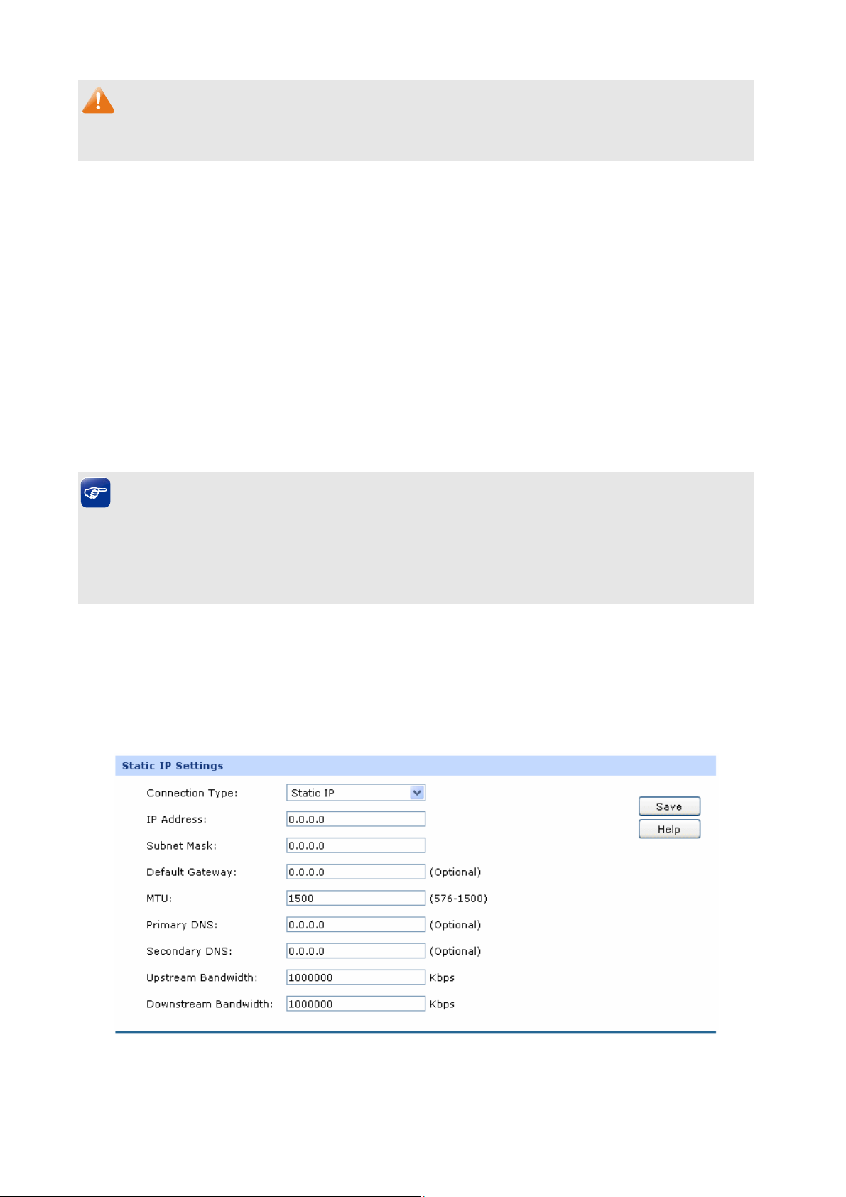
1) Static IP
If a static IP address has been provided by your ISP, please choose the Static IP connection type to
configure the parameters for WAN port manually.
Figure 3-6 WAN – Static IP
The following items are displayed on this screen:
-12-
Page 19

Static IP
Connection Type:
IP Address:
Subnet Mask:
Default Gateway:
MTU:
Primary DNS:
Select Static IP if your ISP has assigned a static IP address for your
computer.
Enter the IP address assigned by your ISP. If you are not clear,
please consult your ISP.
Enter the Subnet Mask assigned by your ISP.
Optional. Enter the Gateway assigned by your ISP.
MTU (Maximum Transmission Unit) is the maximum data unit
transmitted by the physical network. It can be set in the range of
576-1500. The default MTU is 1500. It is recommended to keep the
default value if no other MTU value is provided by your ISP.
Enter the IP address of your ISP’s Primary DNS (Domain Name
Server). If you are not clear, please consult your ISP. It’s not allowed
to access the Internet via domain name if the Primary DNS field is
blank.
Secondary DNS:
Upstream Bandwidth:
Downstream
Optional. If a Secondary DNS Server address is available, enter it.
Specify the bandwidth for transmitting packets on the port.
Specify the bandwidth for receiving packets on the port.
Bandwidth:
2) Dynamic IP
If your ISP (Internet Service Provider) assigns the IP address automatically, please choose the
Dynamic IP connection type to obtain the parameters for WAN port automatically.
-13-
Page 20
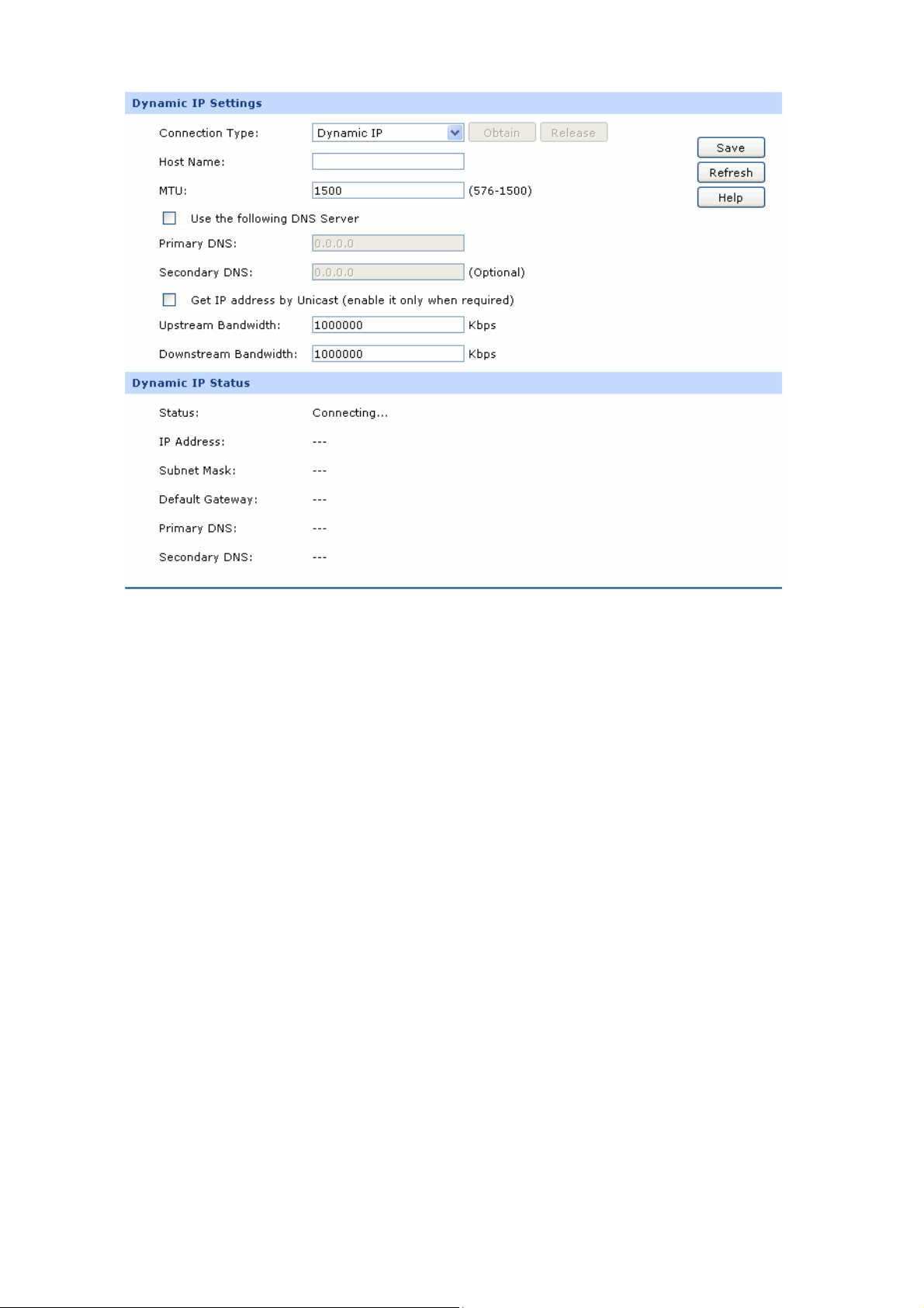
Figure 3-7 WAN – Dynamic IP
The following items are displayed on this screen:
Dynamic IP
Connection Type:
Select Dynamic IP if your ISP assigns the IP address automatically.
Click <Obtain> to get the IP address from your ISP’s server. Click
<Release> to release the current IP address of WAN port.
Host Name:
Optional. This field allows you to give a name for the router. It's
blank by default.
MTU:
MTU (Maximum Transmission Unit) is the maximum data unit
transmitted by the physical network. It can be set in the range of
576-1500. The default MTU is 1500. It is recommended to keep the
Get IP Address by
Unicast:
default value if no other MTU value is provided by your ISP.
The broadcast requirement may not be supported by a few ISPs.
Select this option if you can not get the IP address from your ISP
even if with a normal network connection. This option is not
required generally.
-14-
Page 21

Use the following DNS
Server:
Primary DNS:
Secondary DNS:
Upstream Bandwidth:
Downstream
Bandwidth:
Dynamic IP Status
Status:
Select this option to enter the DNS (Domain Name Server) address
manually.
Enter the IP address of your ISP’s Primary DNS (Domain Name
Server). If you are not clear, please consult your ISP.
Optional. If a Secondary DNS Server address is available, enter it.
Specify the bandwidth for transmitting packets on the port.
Specify the bandwidth for receiving packets on the port.
Displays the status of obtaining an IP address from your ISP.
IP Address:
Subnet Mask:
“Disabled” indicates that the Dynamic IP connection type is not
applied.
“Connecting” indicates that the router is obtaining the IP
parameters from your ISP.
“Connected” indicates that the router has successfully obtained
the IP parameters from your ISP.
“Disconnected” indicates that the IP address has been manually
released or the request of the router gets no response from your
ISP. Please check your network connection and consult your
ISP if this problem remains.
Displays the IP address assigned by your ISP.
Displays the Subnet Mask assigned by your ISP.
Gateway Address:
Primary DNS:
Secondary DNS:
Displays the Gateway Address assigned by your ISP.
Displays the IP address of your ISP’s Primary DNS.
Displays the IP address of your ISP’s Secondary DNS.
-15-
Page 22
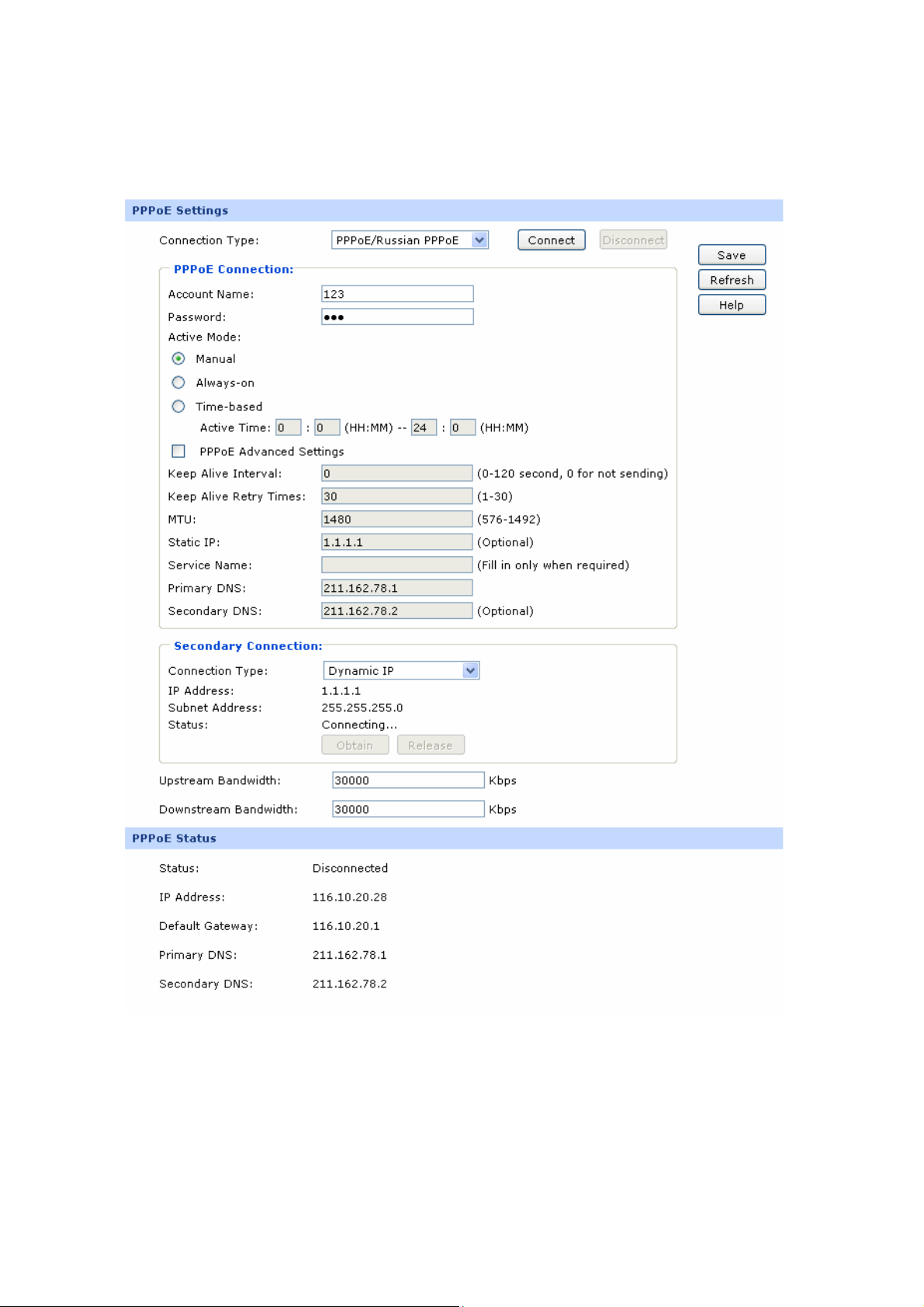
3) PPPoE
If your ISP (Internet Service Provider) has provided the account information for the PPPoE connection,
please choose the PPPoE connection type (Used mainly for DSL Internet service).
Figure 3-8 WAN - PPPoE
The following items are displayed on this screen:
-16-
Page 23

PPPoE Settings
Connection Type:
Account Name:
Password:
Active Mode:
Select PPPoE if your ISP provides xDSL Virtual Dial-up connection.
Click <Connect> to dial-up to the Internet and obtain the IP address.
Click <Disconnect> to disconnect the Internet connection and
release the current IP address.
Enter the Account Name provided by your ISP. If you are not clear,
please consult your ISP.
Enter the Password provided by your ISP.
You can select the proper Active mode according to your need.
Manual: Select this option to manually activate or terminate the
Internet connection by the <Connect> or <Disconnect> button.
It is optimum for the dial-up connection charged on time.
Always-on: Select this option to keep the connection always
on. The connection can be re-established automatically when it
PPPoE Advanced
Settings:
Keep Alive:
MTU:
is down.
Time-based: Select this option to keep the connection on
during the Active time you set.
Check here to enable PPPoE advanced settings.
Once PPPoE is connected, the router will send keep-alive packets
every "Keep Alive Interval" sec and "Keep Alive Retry Times" to
make sure the connection is still alive. If the router does not get the
response from ISP after sending keep-alive packets, then the router
will terminate the connection.
MTU (Maximum Transmission Unit) is the maximum data unit
transmitted by the physical network. It can be set in the range of
576-1492. The default MTU is 1480. It is recommended to keep the
ISP Address:
default value if no other MTU value is provided by your ISP.
Optional. Enter the ISP address provided by your ISP. It's null by
default.
-17-
Page 24

Service Name:
Primary DNS:
Secondary DNS:
Secondary Connection:
Connection Type:
IP Address:
Optional. Enter the Service Name provided by your ISP. It's null by
default.
Enter the IP address of your ISP’s Primary DNS.
Optional. Enter the IP address of your ISP’s Secondary DNS.
Here allows you to configure the secondary connection. Dynamic IP
and Static IP connection types are provided.
Select the secondary connection type. Options include Disable,
Dynamic IP and Static IP.
If Static IP is selected, configure the IP address of WAN port. If
Dynamic IP is selected, the obtained IP address of WAN port is
displayed.
Subnet Address:
Status:
Upstream Bandwidth:
Downstream Bandwidth:
PPPoE Status
Status:
If Static IP is selected, configure the subnet address of WAN port. If
Dynamic IP is selected, the obtained subnet address of WAN port is
displayed.
Displays the status of secondary connection.
Specify the bandwidth for transmitting packets on the port.
Specify the bandwidth for receiving packets on the port.
Displays the status of PPPoE connection.
“Disabled” indicates that the PPPoE connection type is not
applied.
“Connecting” indicates that the router is obtaining the IP
parameters from your ISP.
“Connected” indicates that the router has successfully obtained
the IP parameters from your ISP.
“Disconnected” indicates that the connection has been
manually terminated or the request of the router has no
-18-
Page 25

response from your ISP. Please ensure that your settings are
correct and your network is connected well. Consult your ISP if
this problem remains.
IP Address:
Gateway Address:
Primary DNS:
Secondary DNS:
Displays the IP address assigned by your ISP.
Displays the Gateway Address assigned by your ISP.
Displays the IP address of your ISP’s Primary DNS.
Displays the IP address of your ISP’s Secondary DNS.
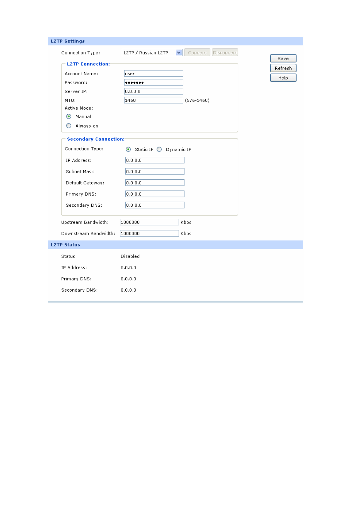
4) L2TP
If your ISP (Internet Service Provider) has provided the account information for the L2TP connection,
please choose the L2TP connection type.
-19-
Page 26
The following items are disp
layed on this screen:
L2TP Settings
Connection T
ype:
Account Name:
Password:
Figure 3-9 WAN - L2TP
Select L2TP if your ISP provides a L2TP connection. Click <Connect>
to dial-up to the Internet and obtain the IP
address. Click
<Disconnect> to disconnect the Internet connection and release the
current IP address.
Enter the Account Name provided by your ISP. If you are not clear,
please consult your ISP.
Enter the Password provi
ded by your ISP.
-20-
Page 27

Server IP:
MTU:
Active Mode:
Secondary
Connection
:
Enter the Server IP provided by your ISP.
i
MTU (Max
mum Transmission Unit) is the maximum data unit
transmitted by the physical network. It can be set in the range of
576-1460. The default MTU is 1460. It is recommended to keep the
default value if no other MTU value is provided by yo
ur ISP.
You can select the proper Active Mode according to your need.
Manual: Select this option to manual
y activate or terminate the
l
Internet connection by the <Connect> or <Disconnect> button. It
is optimum for the dial-up connection charged on time.
Always-on: Select this option to keep the connection always on.
The connection can be re-established automatically when it is
down.
Here allows you to configure the secondary connection. Dynamic IP
and Static IP connection types are provided.
Connection T
ype:
IP Address:
Subnet Mask:
Default Gateway:
Primary DNS/
Secondary DNS:
Select the
secondary connection type. Options include Disable,
Dynamic IP and Static IP.
If Static IP is selected, configure the IP address of WAN port. If
Dynamic IP is selected, the IP
address of WAN port obtained is
displayed.
If Static IP is selected, configure the
subnet mask of WAN port. If
Dynamic IP is select, the subnet mask of WAN port obtained is
displayed.
If Static IP is selected, configure the default gateway. If Dynamic IP is
selected, the obtained default gateway is displayed.
If Static IP is selected, configure the DNS. If Dynamic IP is selected,
the obtained DNS is displayed.
Upstream
Bandwidth:
Specify the bandwidth for transmitting packets on the port.
-21-
Page 28

Downstream
Band
L2TP
Status:
Specify the bandwidth for receiving packets on the port.
width:
Status
Displays the status of PPPoE connection.
“Disabled” indicates that the L2TP connection type is not applied.
“Connecting” indicates that the router is obtaining the IP
parameters from your ISP.
“Connected” indicates that the router has successfully obtained
the IP parameters from your ISP.
“Disconnected” indicates that the connection has been manually
terminated or the request of the router has no response from
your ISP. Please ensure that your settings are correct and your
network is connected well. Consult your ISP if this problem
remains.
IP Address:
Primary DNS:
Secondary DNS:
Displays the IP address assigned by your ISP.
Displays the IP address of your ISP’s Primary DNS.
Displays the IP address of your ISP’s Secondary DNS.
5) PPTP
If your ISP (Internet Service Provider) has provided the account information for the PPTP connection,
please choose the PPTP connection t
ype.
-22-
Page 29
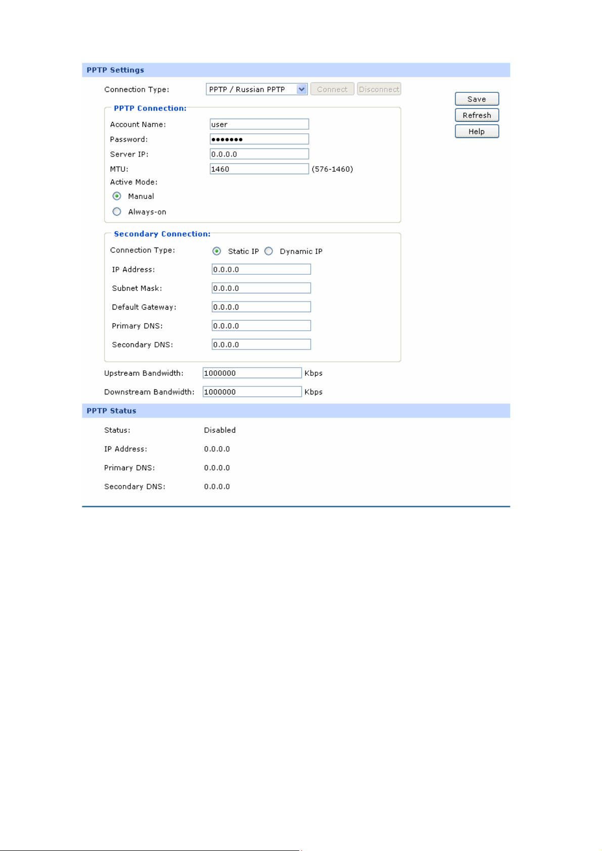
Figure 3-10 WAN - PPTP
The following items are displayed on this screen:
PPTP Settings
Connection Type:
Select PPTP if your ISP provides a PPTP connection. Click
<Connect> to dial-up to the Internet and obtain the IP address. Click
<Disconnect> to disconnect the Internet connection
current IP address.
Account Name:
Enter the Account Name provide
please consult your ISP.
Password:
Enter the Password provided by your ISP.
and release the
d by your ISP. If you are not clear,
-23-
Page 30

Server IP:
MTU:
Active Mode:
Secondary
Connection:
Enter the Server IP provided by your ISP.
MTU (Maxi
ansmitted by the physical network. It can be set in the range of
tr
1460. The default MTU is 1460. It is recommended to keep the
576-
default value if no other MTU value is pro
mum Transmission Unit) is the maximum data unit
vided by your ISP.
You can select the proper Active mode according to your need.
Manual: Select this optio
n to manually activate or terminate the
Internet connection by the <Connect> or <Disco
It’s optimum for the dial-up
Always-on: Select this option to keep the connection always on.
The connection can be re-establ
connection charged on time.
ished automatically when it is
nnect> button.
down.
Here allows you to configure the secondary connection. Dynamic IP
and Static IP connection types are provided.
Connection Type:
IP Address:
Subnet Mask:
Default Gateway:
Primary DNS/
Secondary DNS:
Select the se
condary connection type. Options include Disable,
Dynamic IP and Static IP.
If Static IP is selected, configure the IP address of WAN port. If
Dynamic IP is selected, the IP address of WAN
port obtained is
displayed.
If Static IP is selected, configure the subnet mask of WAN port. If
Dynamic IP is select, the subnet mask of WAN port obtained is
displayed.
If Static IP is selected, configure the default gateway. If Dynamic IP is
selected, the obtained default gateway is displayed.
If Static IP is selected, configure the DNS. If Dynamic IP is selected,
the obtained DNS is displayed.
Upstream Bandwidth:
Downstream
Bandwidth:
Specify the bandwidth for transmitting packets on the port.
Specify the bandwidth for receiving packets on the port.
-24-
Page 31

PPTP Status
Status:
IP Address:
Displays the status of PPTP connection.
“Disabled” indicates that the PPTP connection type is not
applied.
“Connecting” indicates that the router is obtaining the IP
parameters from your ISP.
“Connected” indicates that the router has successfully obtained
the IP parameters from your ISP.
“Disconnected” indicates that the connection has been manually
terminated or the request of the router has no response from
your ISP. Please ensure that your settings are correct and your
network is connected well. Consult your ISP if this problem
remains.
Displays the IP address assigned by your ISP.
Disp P’s Primary DNS.
Primary DNS:
Secondary DNS:
lays the IP address of your IS
Displays the IP address of your ISP’s Secondary DNS.
6) BigPond
If you vice P
r ISP (Internet Ser rovider) has provided the account information for the BigPond
connection, please choose the B
igPond connection type.
-25-
Page 32
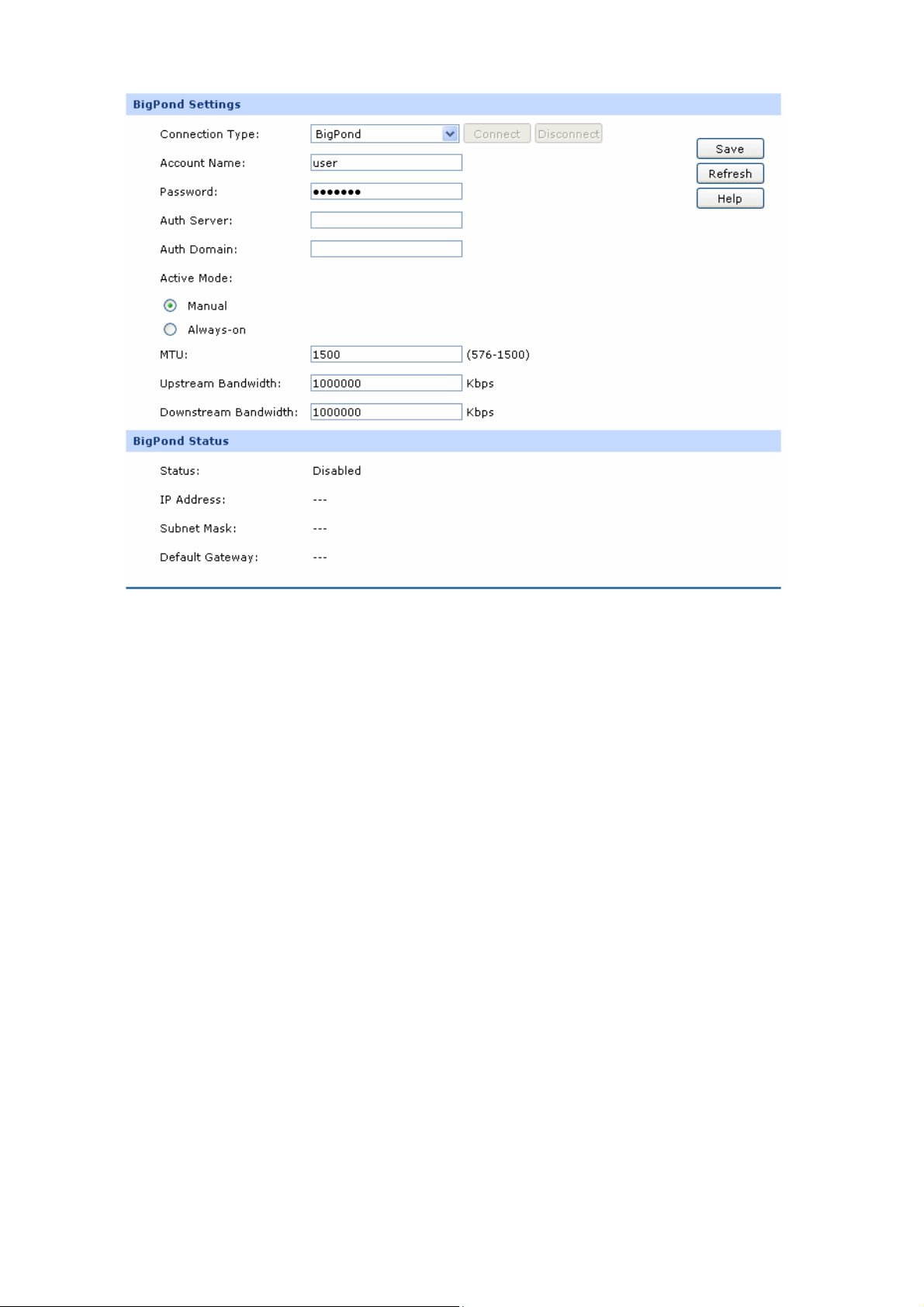
Figure 3-11 WAN – Bigpond
The following items are displayed on this screen:
BigPond Settings
Connection Type:
Select BigPond if your ISP pro
<Connect> to dial-up to the Internet and obtain the IP address. Click
<Disconnect> to disconnect the Internet connection and release the
current IP address.
Account Name:
Enter the Account Name provided by your ISP. If you are not clear,
please consult your ISP.
Password:
Enter the Password provide
consult your ISP.
vides a BigPond connection. Click
d by your ISP. If you are not clear, please
Auth Server:
Auth Domain:
Enter the address of authentication server. It can be IP address or
server name.
Enter the domain name of authentication server. It's only required
the address of Auth Server is a server name.
when
-26-
Page 33

Auth M
ode:
MTU:
Upstream/Downstream
Bandwidth:
You can select the proper Active mode according to your need.
Manual: Select this option to manually activate or terminate the
Internet connection by the <Connect> or <Disconnect> button.
s optimum for the dial-up connection charged on time.
It’
Always-on: Select this option to keep the connection always on.
The connection can be re-established automatically when it is
down.
MTU (Maximum
Transmission Un
it) is the maximum data unit
transmitted by the physical network. It can be set in the range of
576-1500. The default MTU is 1500.
Specify the Upstream/Downstream Bandwidth for the port. To make
"Load Balance" and "Bandwidth Control" take effect, please set
these par
ameters correctly.
BigPond Status
Status:
Displays the status of BigPond connection.
“Disabled” indicates that the BigPond connection type is not
applied.
“Connecting” indicates that the router is obtaining the IP
parameters from your ISP.
“Connected” indicates that the router has successfully
obtained the IP parameters from your ISP.
“Disconnected” indicates that the connection has been
manually terminated or the request of the router has no
response from your ISP. Please en
sure that your settings are
correct and your network is connected well. Consult your ISP if
this problem remains.
IP Address:
Subnet Mask:
Default Gateway:
Displays the IP address assigned
Displays the Subnet Mask assigned by your ISP
by your ISP.
.
Displays the IP address of the default gateway assigned by your
ISP.
-27-
Page 34
Note:
To ensure the BigPond connection re-established normally, please restart the connection at least 5
seconds after the connection is off.
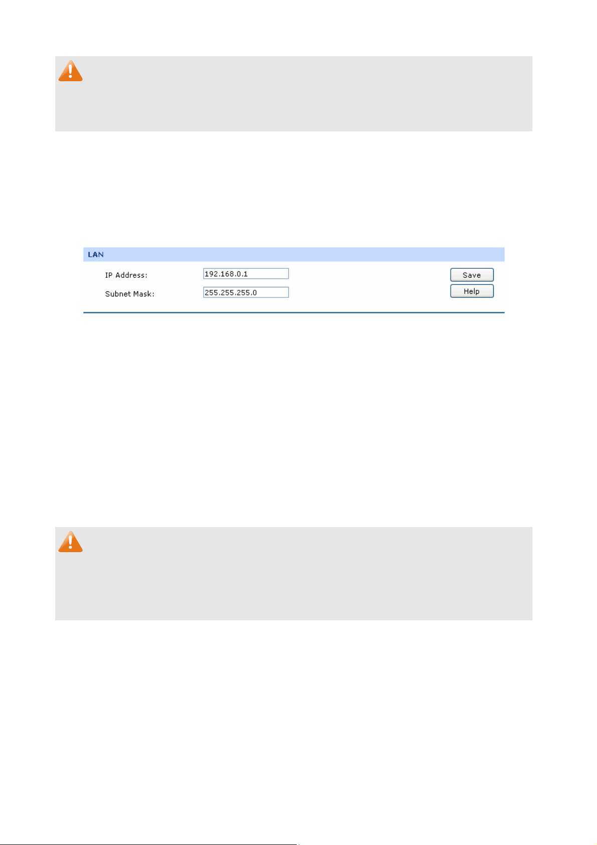
3.1.4 LAN
3.1.4.1 LAN
On this page, you can configure the parameters for LAN port of this router.
Choose the menu Network→LAN→LAN to load the following page.
Figure 3-12 LAN
The fo displayed
llowing items are on this screen:
LAN
IP Address:
Subnet Mask:
Note:
If the LAN IP address is changed, you must use the new IP address to log into the router. To guarantee
a normal communication, be sure to dress and the Subnet Mask of the Hosts on set the Gateway ad
the LAN to th address and
e new LAN IP the Subn
Enter the LAN IP address of the router. 192.168.0.1 is the default IP
address. The Hosts in LAN can access the router via this IP address.
It can be changed according to your network.
Enter the Subnet Mask.
et Mask of the router.
The default subnet mask is 255.255.255.0.
3.1.4.2 DHCP
The router with its DHCP (Dyna erver enabled can automatically
assign an IP address to the computers in the local area network.
Choose the menu Network→LA
mic Host Configuration Prot
N→DHCP to load the following page.
-28-
ocol) s
Page 35

Figure 3-13 DHCP Settings
The following items are displayed on this screen:
DHCP Settings
DHCP Server:
Start IP Address:
End IP Address:
Lease Time:
Enable or disable the DHCP server on your router. To enable the
router to rameters to the computers in the LAN
assign the TCP/IP pa
automatically, please select Enable.
er the Start IP address to define a range for the DHCP server to
Ent
assign dynamic IP addresses. This address should be in the same IP
address subnet with the router’s LAN IP address. The default address
is 192.168.0.2.
Enter the End IP address to define a range for the DHCP
server to
assign dynamic IP addresses. This address should be in the same IP
address subnet with the router’s LAN IP address. The default address
is 192.168.0.254.
Specify the length of time the DHCP server will reserve the IP address
Default Gateway:
Default Domain:
for each computer. After the IP address expired, the client will be
automatically assigned a new one.
Optional. Enter the Gateway address to be assigned. It is
recommended to enter the IP address of the LAN port of the router.
O f your network.
ptional. Enter the domain name o
-29-
Page 36
Primary DNS:
Secondary D
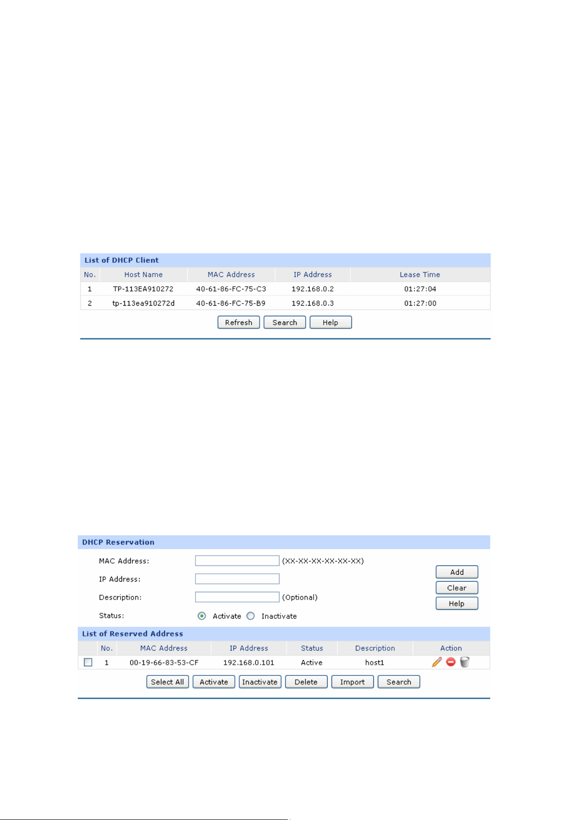
3.1.4.3
On this page, you can view the information about all the DHCP clients connected to the router.
Choose the menu Network→LAN→DHCP Client to load the following page.
DHCP Client
NS:
Optional. Enter the Primary DNS server add
ISP. It is recommended to enter the IP address of the LAN port of the
router.
Optional. If a Secondary DNS Server
address is available, enter it.
ress provided by your
Figure 3-14 DHCP Client
You ca on of the DHCP clients in this table. Click the Refresh button for the updated
information.
n view the informati
3.1.4.4 DHCP Reservation
DHCP Reservation feature allows you to reserve an IP address for the specified MAC address. The
client with this MAC
server.
DHCP
Choose the menu Network→LAN→DHCP Reservation to load the following page.
address will always get the same IP address every time when it accesses the
Figure 3-15 DHCP Reservation
The following items are displayed on this screen:
-30-
Page 37

DHCP Reservation
MAC Address:
IP Address:
Description:
Status:
List of Rese
In this table, you can view the information of the entries and edit them by the Action buttons.
The first en
computer with the MAC address 00-19
rved Address
try in Figure 3-15 indicates: The IP address 192.168.0.101 is reserved for the
Enter the MAC address of the computer for which you want to reserve
the IP address.
Enter the reserved IP address.
Optional. Enter a description for the entry. Up to 28 characters can be
entered.
Activate or Inactivate the corresponding entry.
-66-83-53-CF, and this entry is activated.
Note:
It's recommended that users bind the IP address and the MAC address in 3.4.1.1 IP-MAC Binding ,
then import the entries from the IP-MAC binding table to the List of Reserved Address in buck by
clicking <Import> button in Figure 3-15 DHCP Reservation.
3.1.5 DMZ
DMZ (Demilitarized Zone) is a network which has fewer default firewall restrictions than the LAN does.
TL-ER6120 provides a DMZ port to allow all the local hosts connected to this port to be exposed to the
Internet for some special-purpose services, such as such as Internet gaming and video-conferencing.
The DMZ physical port can work in Public mode and Private mode.
In Public mode, the D
mode using public IP address. However, the Hosts in DMZ cann
MZ port allows the Hosts in DMZ to directly communicate with Internet via routing
ot access LAN.
-31-
Page 38
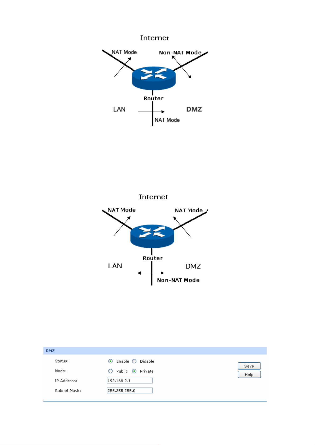
Figure 3-
In Private mode, the DMZ port allows the Hosts in DMZ to access Internet via NAT mode which
translates private IP addresses within DMZ to public IP addresses for transport over Internet. The
Hosts Z can directly communicate with LAN using the private IP addresses within the different in DM
subnet of LAN.
16 DMZ – Public Mode
Figure 3-17 DMZ – Private Mode
3.1.5.1 DMZ
This page allows you to configure the DMZ port of TL-ER6120.
Choose the menu Network→DMZ→DMZ to load the following page.
Figure 3-18 DMZ
-32-
Page 39

The following items are displayed on th
DMZ
Status:
Mode:
IP Address:
Subnet Mask:
Tips:
The DHCP service, DHCP Client and DHCP Reservation functions are available when the DMZ port is
is screen:
Activate or inactivate this entry. The DMZ port functions
LAN port when it’s disabled.
Select the mode for DMZ port to control the connection way among
DMZ, LAN and Internet. Options include: Public and Private.
Enter the IP address of DMZ port.
Enter the Subnet Mask of DMZ port.
as a normal
enabled. For the con uratio i sfig n n tructions, please refer to section 3.1.4.1 to.3.1.4.4.
Note:
When the D service of DMZ port if MZ port is enabled in Public Mode, please do not enable the DHCP
your ISP ccess provides a single public IP address. Otherwise, the Hosts in DMZ will be unable to a
Internet nor address rmally. If an IP ange is provided by your ISP, please configure the DHCP pool
based ess range.
on the IP addr
3.1.6 MAC Address
The MAC (Media Access Contro
need to be changed commonly.
Set the MAC Address for LAN port:
In a complex network topology with all the ARP bound devices, if you want to use TL-ER6120 instead
of the current router in a network node, you can just set the MAC address of TL-ER6120‘s LAN port
the same to the MAC address of the previous router, which can avoid all
l) address, as the unique identifier of the router in network, does not
the devices under this
network node to upda
Set the MAC Address for WAN port:
In the condition that your ISP has bound the account an
want to change the di
TL-ER6120’s WAN port the same to the MAC address
Internet connection.
te their ARP binding tables.
d the MAC address of the dial-up device, if you
al-up device to be TL-ER6120, you can just set the MAC address of
-33-
of the previous dial-up device for a normal
Page 40
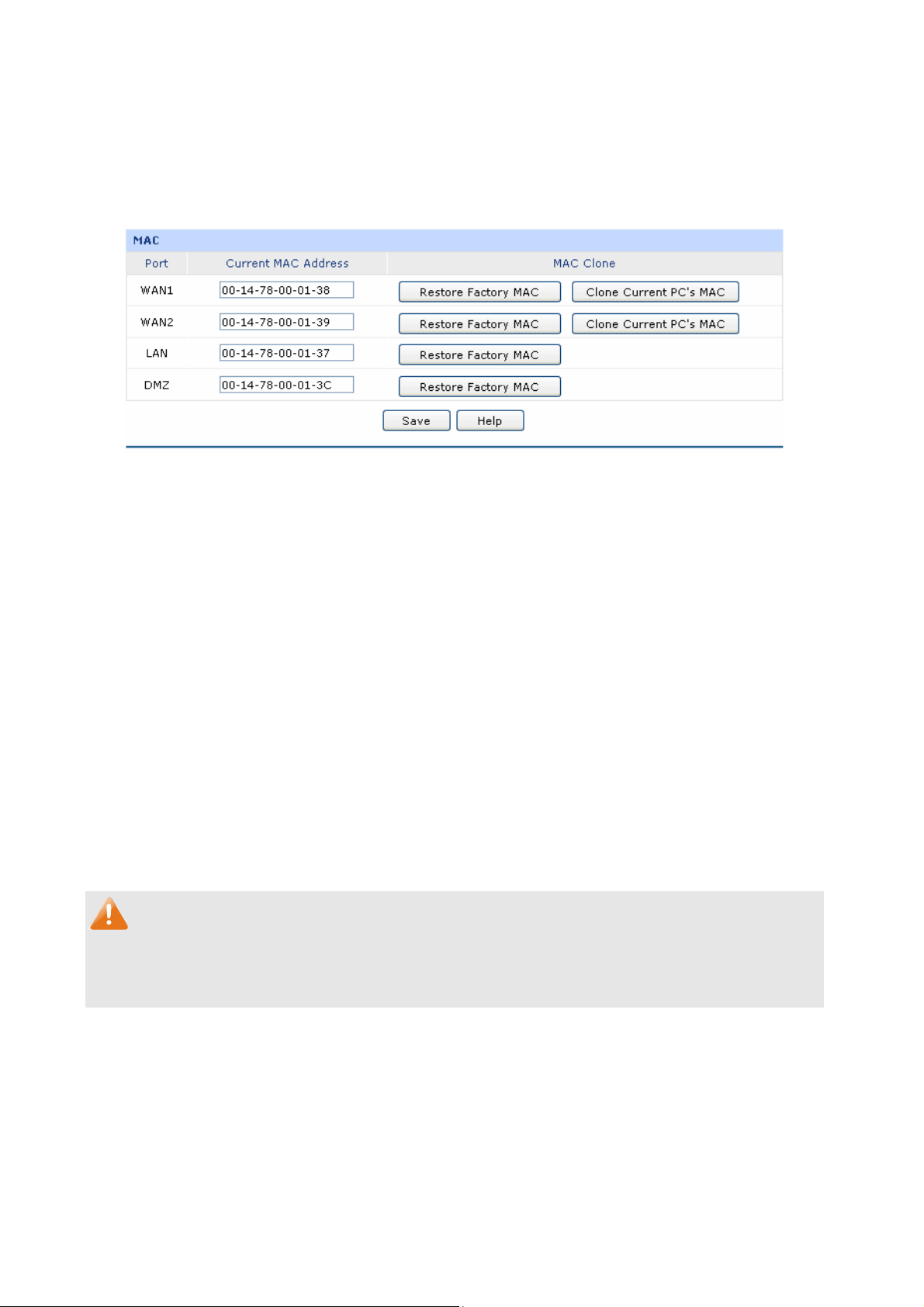
Set the MAC Address for DMZ port:
The application of MAC address for DMZ port is similar to that
Choose the menu Network→MAC Address→MAC Address to load the following page.
Figure 3-19 MAC Address
The following items are displayed on this screen:
MAC Address
for LAN port.
Port:
Current
MAC Clo
Note:
To avo of MAC adid a conflict dress on the local area network, it’s not allowed to set the MAC address
of the router’s LAN port to th ss of the current management PC.
MAC Address:
ne:
Displays the port type of the router.
Displays the current MAC address of the port.
It’s only available for WAN port. Click the <Restore Factory MAC>
button to
click the <Clone Current PC’s MAC> button to clone the MAC
address of the PC you are currently using to configure the router.
Then click <Save> to
e MAC addre
restore the MAC address to the factory default value or
apply.
3.1.7 Switch
Some basic switch port man ich facilitates you to
agement functions are provided by TL-ER6120, wh
monitor the traffic and manage the network effectively.
3.1.7.1 Statistics
Statistics screen displays the detailed traffic information of each port, which allows you to monitor the
traffic and locate faults promptly.
-34-
Page 41
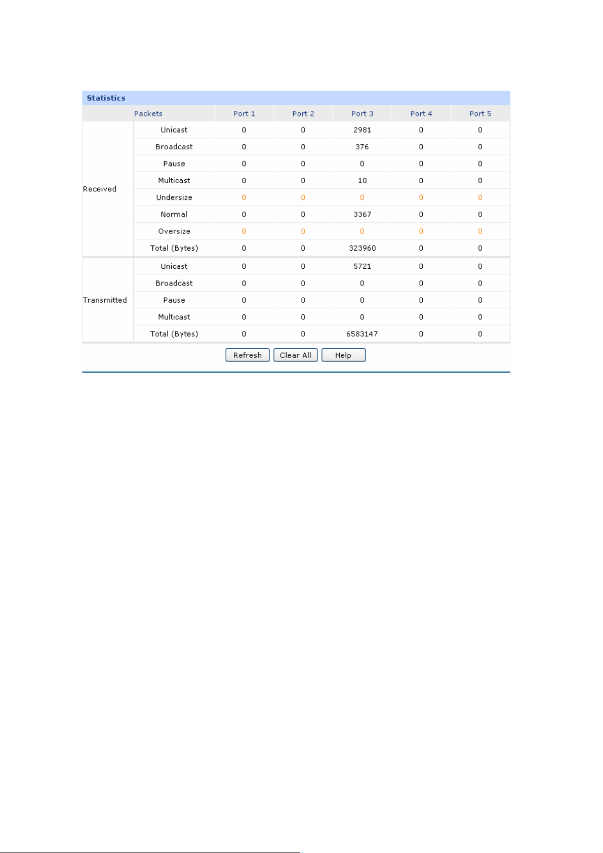
Choos u Network→e the men Switch→Statistics to load the following page.
Figure 3-20 Statistics
The following items are displayed on this screen:
Statistics
Unicast:
Displays the number of normal unicast packets r
on the port.
Broadcast:
Displays the number of normal broadcast packets received or
transmitted on the port.
Pause:
Displays the number of flow control frames received or transmitted on
the port.
Multicast:
Displays the number of normal multicast packets received or transmitted
on the port.
eceived or transmitted
Undersize:
Displays the number of the received frames (including error frames) that
are less than 64 bytes long.
-35-
Page 42
Normal
Oversiz
Total (Bytes):
Click the <Clear All> button to
Tips:
The Port 1/2/3/4/5 mentioned in this User Guide refers to the WAN1/2 port and LAN1/2/3 port on the
router.
:
e:
Displays the number of the received packets (including error frames) that
are between 64 bytes and the maximum frame length. The maximum
untagged frame this router can support is 1518 bytes long and the
maximum t
Displays the number of the received packets (including error fr
are longer than the maximum frame.
Displays the total number of the received or transmitted packets
(including error frames).
clear all the traffic statistics.
agged frame is 1522 bytes long.
ames) that
3.1.7.2
Port Mirror, the packets obta rd copies of packets from one/multiple
ports (mirrored port) to a specific port (mirroring port). Usually, the mirroring port is connected to a data
ose device, which ed to analyze the mirrored packets for monitoring and troubleshooting the
diagn is us
network.
Choose the menu Network→Switch→Port Mirror to load the following page.
Port Mirror
ining technology, functions to forwa
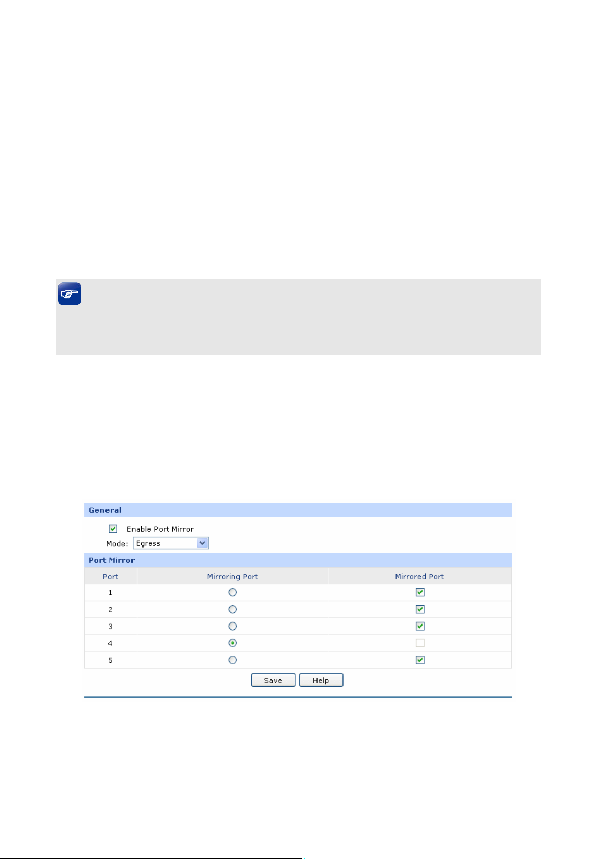
Figure 3-21 Port Mirror
The following items are displayed on this screen:
-36-
Page 43

General
Enable Port Mirror:
Mode:
Port Mirror
Mirroring Port:
Check the box to enable the Port Mirror function. If unchecked, it will be
disabled.
Select the mode for the port mirror function. Options include:
Ingress: When this mode is selected, only the incoming packets sent
by the mirrored port will be copied to the mirroring port.
Egress: When this mode is selected, only the outgoing packets sent
by the mirrored port will be copied to the mirroring port.
Ingress&Egress: When this mode is selected, both the incoming and
outgoing packets through the mirrored port will be copied to the
mirroring port.
Select the Mirroring Port to which the traffic is copied. Only one port can
be selected as the mirroring port.
Mirrored
Port:
Select the Mirrored Port from which the traffic is mirrored. One or multiple
ports can be selected as the mirrored ports.
The entry in Figure 3-21 indicates: The outgoing packets sent by port 1, port 2, port 3 and port 5
(mirrore
d ports) will be copied to port 4 (mirroring port).
Tips:
If both the mirrored port and the mirroring port are the LAN ports, these two LAN ports should be in the
same Port VLAN. For example, if port 3 (the mirroring port) and port 4 (the mirrored port) are the LAN
ports, the Port Mirror function can take effect only when port 3 and port 4 are in the same Port VLAN.
Application Example:
To monitor all the traffic and analyze th n enterprise’s network, please set the e network abnormity for a
Port Mirror function as below:
-37-
Page 44
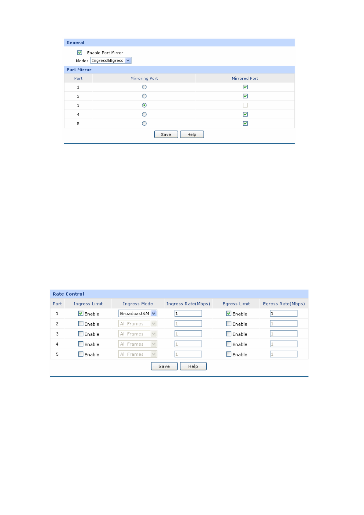
1) before ror function and select the
Check the box Enable Port Mirror to enable the Port Mir
Ingress & Egress mode.
2) Select Port 3 to be the Mirroring Port to monitor all the packets of the other ports.
3) Select all the other ports to be the Mirrored Ports.
4) Click the <Save> button to
3.1.7.3 Rate Control
On this page, you can control the traffic rate for the specific packets o
network flow.
Choose the menu Network→Switch→Rate Control to load the following page.
apply.
n each port so as to manage your
Figure 3-22 Rate Control
The following items are displayed on this screen:
Rate Control
Port:
Ingress Limit:
Displays the port number.
Specify whether to enable the Ingress Limit feature.
-38-
Page 45
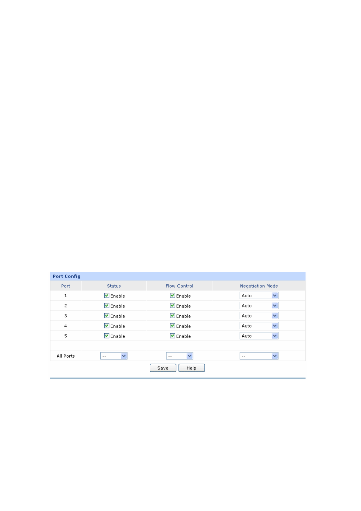
Ingress Mode:
Ingress Rat
e:
Egress Limit:
Egress Rate:
Select the
All Frames: Select this option to limit
Broadcast & Multicast: Select this option to limit broadcast frame and
Broadcast: Select this option to limit the broadcast frame.
Specify the limit rate for the ingress p
Specify whether to enable Egress Limit feature.
Specify the limit rate for the egress packets.
Ingress Mode for each port. Options include:
all the frames.
multicast fra
me.
ackets.
The first entry in Figure 3-22 indicates: The Ingress and Egress Limits are enabled for port 1. The
Ingress mode is Flood while the Ingress and Egr
ess Rates are 1Mbps. That is, the receiving rate for
the ingress packets of Flood mode will not exceed 1Mbps, and the transmitting rate for all the egress
packets will not exceed 1Mbps.
3.1.7.4 Port Config
On this page, you can configure the basic parameters for the ports.
Choose the menu Network→Switch→Port Config to load the following page.
Figure 3-23 Port Config
The following items are displayed on this screen:
Port Config
Status:
Specify whether to enable the port. The packets can be transported via
this port after being enabled.
-39-
Page 46
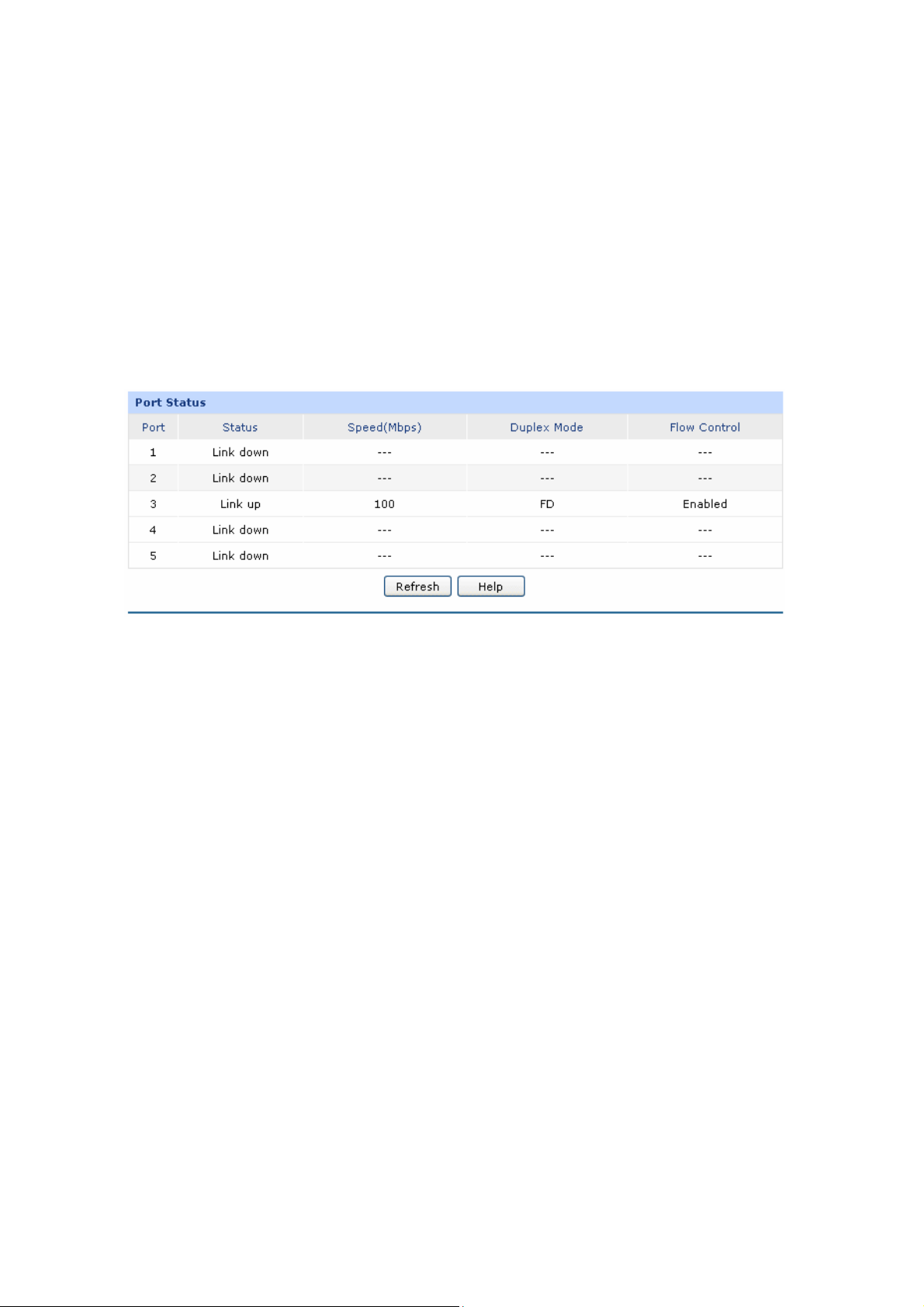
Flow Control:
Negotiation Mode:
All Ports:
Allows you to enable/disable the Flow Control function.
Select the Negotiation Mode for the port.
Allows you to configure the parameters for all the ports at one time.
3.1.7.5 Port Status
On this page, you can view the current status of ea
Choose the menu
Network→Switch→Port Status to load the following page.
ch port.
Figure 3-24 Port Status
3.1.7.6 Port VLAN
A VLAN (Virtual Local Area Network) is a network topology configured according to a logical scheme
rather than the physical layout, which allows you to divide the physical LAN into multiple logical LANs
so as to control the communication among the ports
The VLAN function
creating VLANs in a
has a broadcast domain of its own. Hosts in the same VLA
are in a LAN. However, hosts in different VLANs cannot communicate
Therefore, broadcast p
TL-ER6120 provides the Port VLAN function, which allows you to create multiple logical VLANs for the
LAN ports based on their port numbers.
Choose the menu Network→Switch→Port VLAN to load the following page.
can prevent the broadcast storm in LANs and enhance the network security. By
physical LAN, you can divide the LAN into multiple logical LANs, each of which
ackets are limited in a VLAN.
.
N communicate with one another as if they
with one another directly.
-40-
Page 47
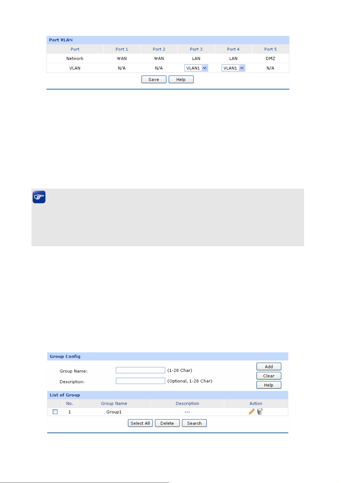
Figure 3-25 Port VLAN
The following items are displayed on this screen:
Port VLAN
Network:
VLAN:
Tips:
● The Port VLAN can only be created among the LAN ports.
● The change of DMZ status will affect the configurations of Port VLAN. You're recommended to
check or reconfigure the Port VLAN if the status of DMZ is changed.
Displays the current logical network o
Select the desired VLAN for the port.
f the physical port.
3.2 User Group
The User Group function is used to d management, so that you can
perform other applications such as Bandwidth Con
group.
3.2
.1 Group
group different users for unifie
trol, Session Limit, and Access Control etc. on per
On this page you can define the group for management.
Choose the User Group
menu →Group to load the following page.
Figure 3-26 Group Configuration
-41-
Page 48
The following items are displayed on this screen:
Group Config
Group Name: Specify a unique name for the group.
Description: Give a description for the group. It's optional.
List of Group
In this table, you can view the information of the Groups and edit them by the Action buttons.
3.2.2 User
On this page, you can configure the User for the group.
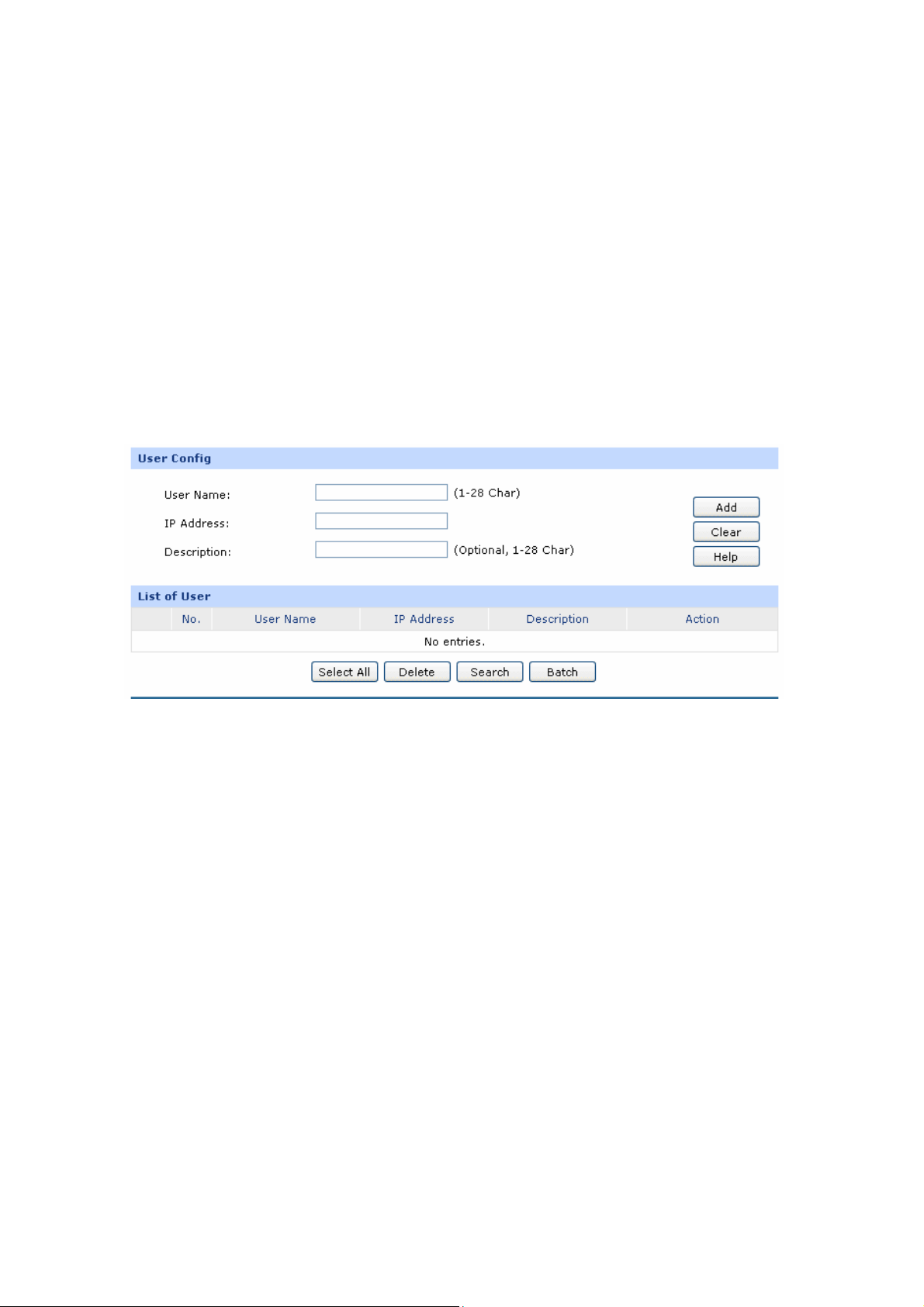
Choose the menu User Group→User to load the following page.
Figure 3-27 User Configuration
The following items are displayed on this screen:
User Config
User Name
IP Address:
:
Specify a unique name for the user.
Enter the IP Address of the user. It c
broadcast address of the port.
Description:
List of User
In this t
able, you can w the information of the Users and edit them by the Action buttons.
Give a description to the user for identification. It's optional.
vie
3.2.3 View
annot be
the network address or
On this p
age, you can configure the U
ser View or Group View.
Choose the menu User Group→View to load the following page.
-42-
Page 49
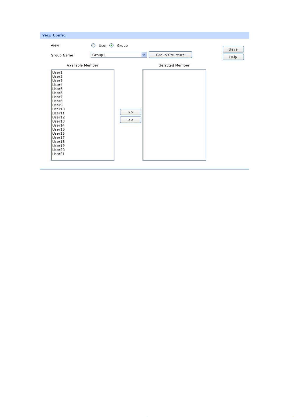
Figure 3-28 View Configuration
The following items are displayed on this screen:
View Config
View:
User Name:
Available Group:
Selected Group:
Group Nam
e:
Group Structure:
Select the desired view for configuration.
Select the name of th
Displays the Groups that the User can join.
Displays the Groups to whic
Select the name of the desired Group.
Click this button to view the tree structure of this group. All the members of
e desired User.
h this User belongs.
Available Member:
Selected Member:
this group will be displayed, including Users and sub-Groups. The Group
Names are displayed in bold.
Displays the Users and the Groups which can be added into this group.
Displays the members of this group, including Users and Groups.
-43-
Page 50
3.3 Advanced
3.3.1 NAT
NAT (Network Address Translation) is the translation between private IP and public IP, which allows
private network users to visit the public network using private IP addresses.
With the explosion of the Internet, the number of available IP addresses is not enough. NAT provides a
way to allow multiple private hosts to access the public network with one public IP at the same time,
which alleviates the shortage of IP addresses. Furthermore, NAT strengthens the LAN (Local Area
Network) security of the network since the address of LAN host never appears on the Internet.
3.3.1.1 NAT Setup
On this page, you can set up the NAT function.
Choose the menu Advanced→NAT→ age.
The ispl
followin
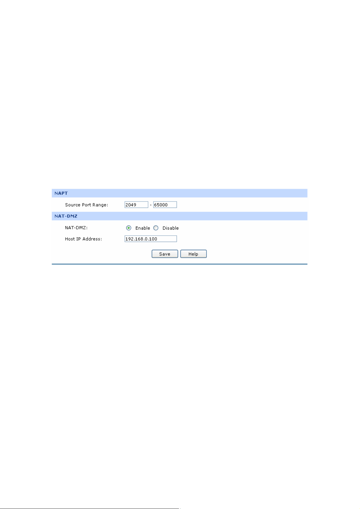
NAPT
Source Port Range:
NAT-DMZ
g items are d ayed on this screen:
Enter the source port range between 2049 and 65000, the span of which
must be not less than 100.
NA
T Setup to load the following p
Figure 3-29 NAT Setup
T-DMZ:
NA
Host IP Address:
Enable or disable NAT-DMZ. NAT DMZ is a special service of NAT
application, which can be considered as a default forwarding rule. When
NAT DMZ (Pseudo DMZ) is enabled, all the data initiated by e
network falling short of the current connections or forwarding rules will b
forwarded to the preset NAT DMZ host.
Enter the IP address of the host specified as NAT DMZ server.
3.3.1.2 One-to-One NAT
On this page, you can configure the One-to-One NAT.
-44-
xternal
e
Page 51
NAT→One-to-One NAT to load the following page. Choose the menu Advanced→
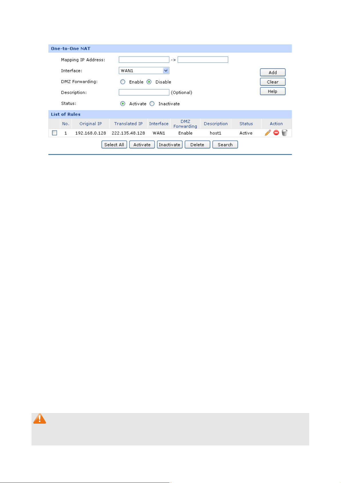
Figure 3-30 One to One NAT
The following items are displayed on this screen:
One-to-One NAT
Mapping IP
In
terface:
D g:
MZ Forwardin
Description:
Status:
List of Rules
In this t
able, you can view the
Address:
Enter the Original IP
Address in the first checkbox and Translated
IP Address in the second checkbox. TL-ER6120 allows mapping from LAN
port
to WAN port and DMZ in LAN Mode.
Sele
ct an interface for forwarding data packets.
Ena g. The packets transmitted to the
ble or disable DMZ Forwardin
Translated IP Address will be forwarded to the host of Original IP if DMZ
warding is enabled.
For
Give a description for the entry.
Activate or inactivate the entry.
information of the entries and edit them by the Action buttons.
The first entry in Figure 3-30 indicates: The IP address of host1
in local network is 192.168.0.128
and the WAN IP address after NAT mapping is specified to be 222.135.48.128. The data packets
are transmitted from WAN1 port. DMZ Forwarding and this entry are both activated.
Note:
One-to-One NAT entries take effect only when the Connection Type of WAN is Static IP. Changing the
Connection type from Static IP to other ones will make the entries attached to the interface disabled.
-45-
Page 52
3.3.1.3 Multi-Nets
Multi-Nets NAT function a
Internet via NAT.
Choose the menu Advanced→NAT→Multi-Nets NAT to load the following page.
The following items are displayed on this screen:
NAT
llows the IP under LAN or DMZ port within multiple subnets to access the
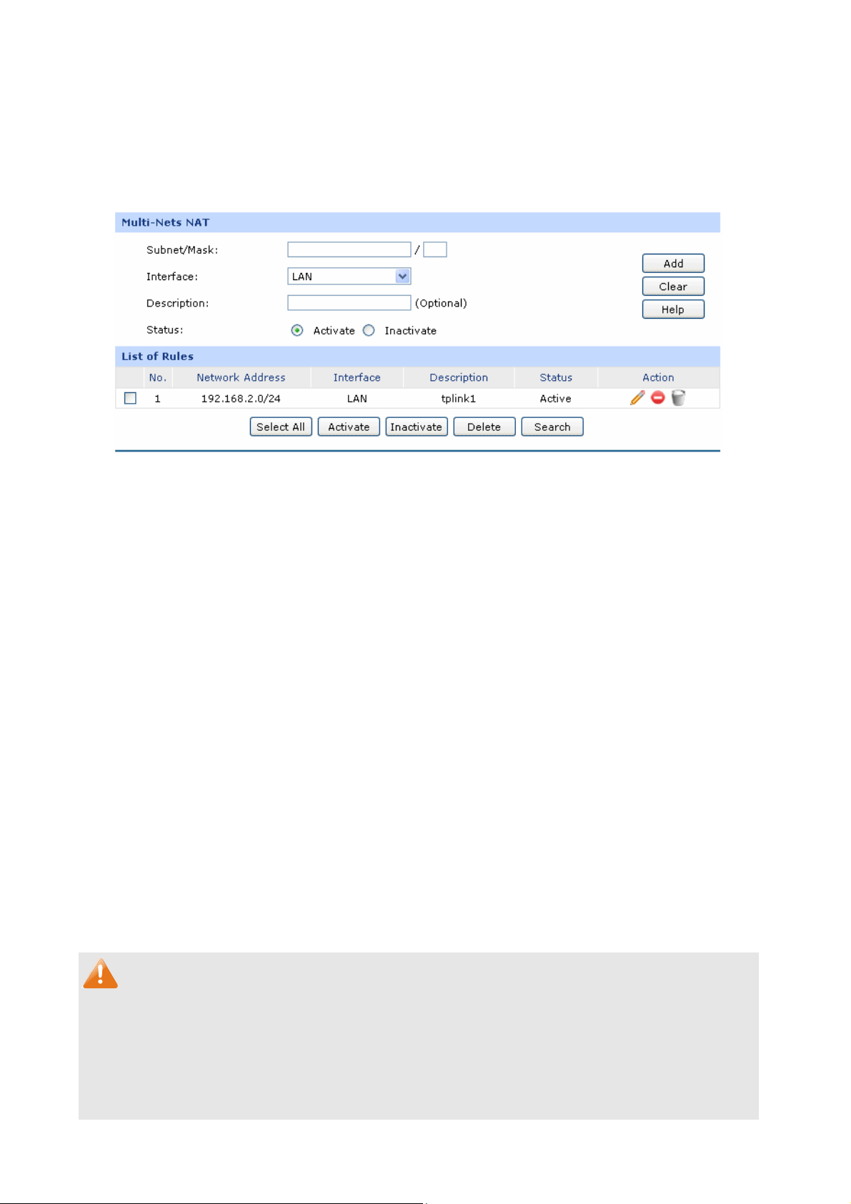
Figure 3-31 Multi-Nets NAT
Multi-Nets NAT
Subnet/Mask:
Interface:
Description:
Status:
list of Rules
You can view the information of the entries and edit them by the Action buttons.
The first entry in Figure 3-31 indicates that: This is a Multi-Nets NAT entry named tplink1. The
subnet under the LAN port of the router is 192.168.2.0/24 and this entry is activated. After the
corresponding Static Route entry is set, the hosts within this subnet can access the Internet
through the router via NAT.
Enter the subnet/mask to make the address range for the entry.
Select the interface for the entry. You can select LAN or DMZ port.
Give a description for the entry.
Activate or inactivate the entry.
Note:
● Multi-Nets NAT entry takes effect only when cooperating with the corresponding Static Route
entries.
● The DMZ port will display in the drop-down list only when the DMZ port is enabled.
● For detailed setting of subnet mask, please refer to the Appendix BFAQ
-46-
Page 53
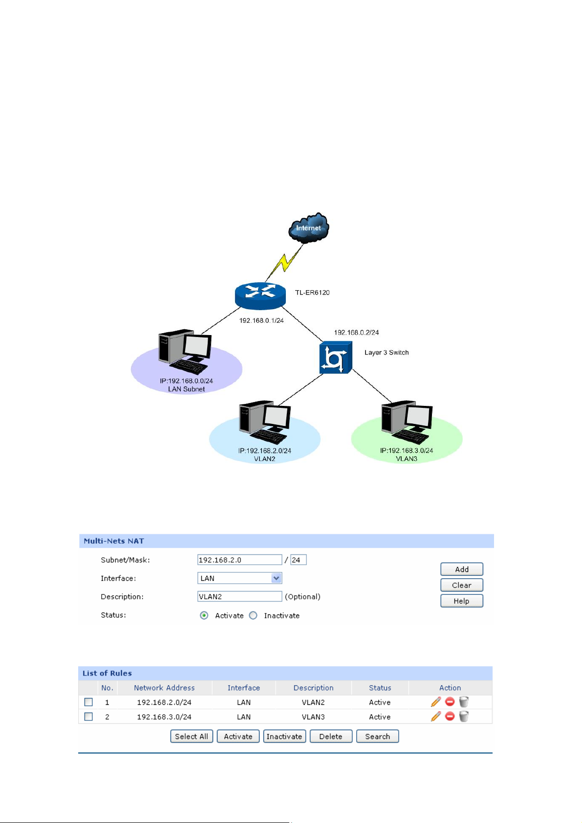
Application Example:
Network Requirements
The LAN subnet of TL-ER6120 is 192.168.0.0 /24, the subnet of VLAN2 under a thre
e layer switch is
192.168.2.0 /24, while the subnet of VLAN3 is 192.168.3.0 /24. The IP of VLAN for cascading the
switch to the router is 192.168.0.2. Now the hosts within VLAN2 and VLAN3 desire to access the
Internet.
The network topology is shown as the following:
Configuration procedure
1. Establish the Multi-Nets NAT entries with Subnet/Mask of VLAN2 and VLAN3.
The configured entries are as follows:
-47-
Page 54
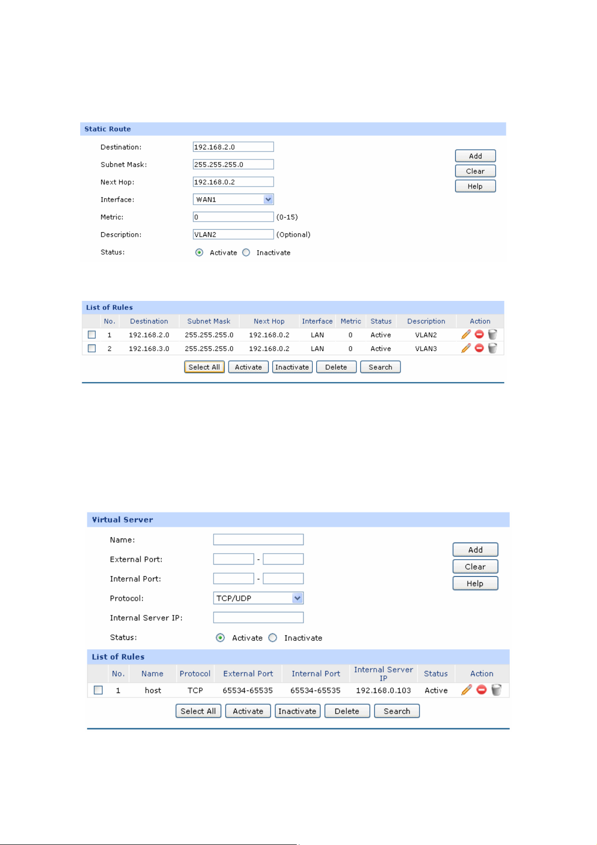
2. Then set the correspo
the router and the three layer switch into the Next Hop field.
Choos nu Advanced→Routi
The Static Route entry is as follows:
e the me ng→Static Route to load the following page.
nding Static Route entry, enter the IP address of the interface connecting
3.3.1.4 Virtual Server
Virtual server sets up public services in your private network, such as DNS, Email and FTP, and
defines a service port. All the service requests to this port will be transmitte
appointed by the router via IP address.
Choose the m
enu Advanced→NAT→Virtual Server to load the following page.
d to the LAN server
Figure 3-32 Virtual Server
The following items are displayed on this screen:
-48-
Page 55

Virtual Server
Name:
External Port:
Internal Port:
Protocol:
Internal Server IP:
Status:
Enter a name for Virtual Server entries. Up to 28 characters can be
entered.
Enter the service port or port range the router provided for accessing
external network. All the requests from Internet to this service port or
port range will be redirected to the specified server in local network.
Specify the service port of the LAN host as virtual server.
Specify the protocol used for the entry.
Enter the IP internal server for the entry. All
the requests fro
redirected to this host.
Activate or inactivate the entry.
address of the specified
m the Internet to the specified LAN port will be
Note:
● The External port and Internal Port should be set in the range of 1-65535.
● The external ports of different entries should be different, whereas the internal ports can be the
same.
L
ist of Rules
In this table, you can view the information of the entries and edit them by the Action buttons.
The first entry in Figure 3-3
dat
a packets from Interne of the router will be redirected to the port
65534-65535 of the LAN host with IP address of 192.168.0.103, and this entry is activated.
3.3.1 g
.5 Port Triggerin
Some applications require multi t games, video conferencing, Internet
calling, P2P download and so on. Port Triggering is used for those applications requiring multiple
c
onnections.
2 indicates: This is a Virtual Server entry named host1, all the TCP
t to port 65534-65535
ple connections, such as Interne
When an application initiates a connection to the trigger port, all the ports corresponding to the
incoming port will open for follow-up connections.
Choose the menu Advanced→NAT→Port Triggering to load the following page.
-49-
Page 56
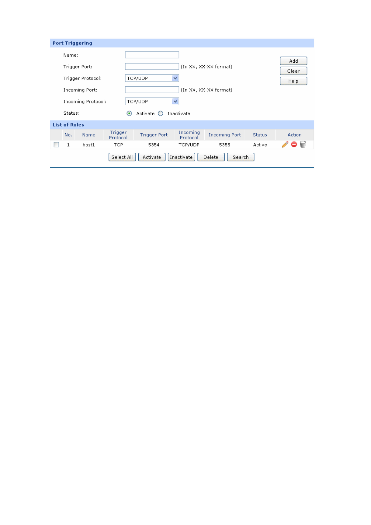
Figure 3-33 Port Triggering
following items are displayed on this screen: The
Port Triggering
Name:
Trigger Port:
Trigger Protocol:
Incoming Port:
Incoming Protocol:
Enter a name for Port Triggering entries. Up to 28 characters can be
entered.
Enter the trigger port number or the
range of port. Only when the
trigger port initiates connection will all the corresponding incoming
ports open and provide service for the applications, otherwise the
incoming ports will not open.
Select the protocol used for trigger port.
Enter the incoming port number or range of port numbers The
.
incoming port will open for follow-up connection after the trigger port
initiates connectio
Select the protocol use
n.
d for incoming port.
Status:
Activate or inactivate the entry.
-50-
Page 57
Note:
● The Trigger Port and Incoming Port should be set in the range of 1-65535. The Incoming Port can
be set in a continuous range such as 8690-8696.
● The router supports up to 5 groups of 16 Port Triggering entries. Each entry supports at most
trigger ports and overlapping between the ports is not allowed.
● Each entry supports at most 5 groups of incoming ports and the sum of incoming ports you set for
each entry should not be more than 1
List of Rules
In this table, you can view the information of the entries and edit them by the Action buttons.
The first entry in Figure 3-33 indicates that: This is a Port T
LAN host initiate
UDP
protocol. This entry is activated.
s a TCP request via port of 5354, the incoming port 5355 will open for TCP and
00.
riggering entry named host1, When the
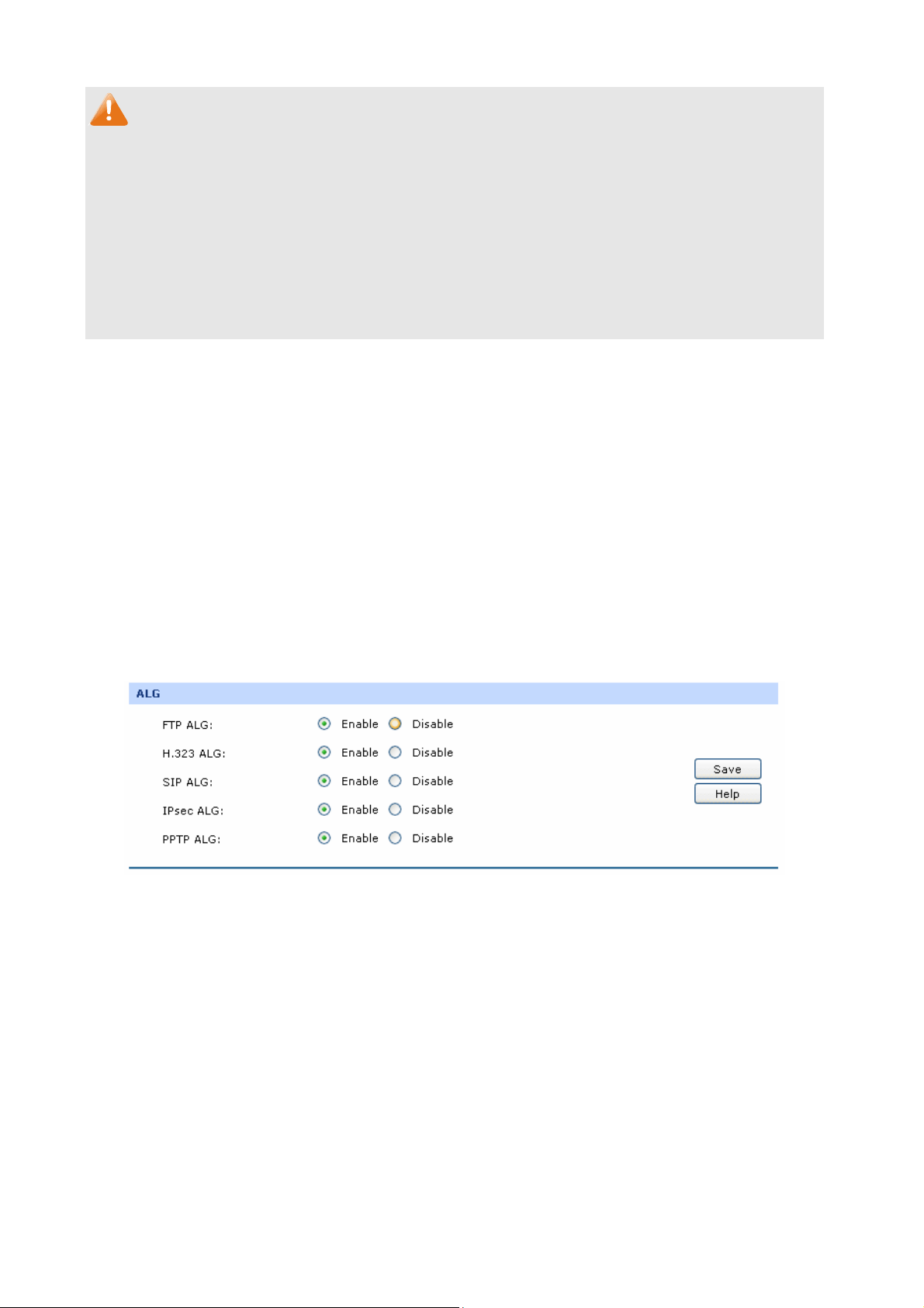
3.3.1.6 ALG
Some special protocols such as FTP, H.323, SIP, IPsec and PPTP will work properly only when ALG
(Application Layer Gateway) service is enabled.
Choose the menu Advanced→NAT→ALG to load the following page.
Figure 3-34 ALG
The following items are displayed on this screen:
ALG
FTP ALG:
H.323 ALG:
Enable or disable FTP ALG. The default setting is enabled. It is
recommended to keep the default setting if no special requirement.
Enable or disable H.323 ALG. The default setting is enabled. H.323 is
used for various applications such as NetMeeting and VoIP.
-51-
Page 58
SIP ALG:
IPsec ALG:
PPTP ALG:
3.3.2 Contro
Traffic Control functions to contro
this way, the network bandwid ributed and utilized.
Traffic l
Enable or
recommended to keep the default setting if no special requirement.
Enable or disable IPsec ALG. The default setting is enabled. It is
recommended to keep default if no special re
Enable or disable PPTP ALG. The default setting is enabled. It is
recommended to keep default if no special requirement.
l the bandwidth by configuring rules for limiting various data flows. In
th can be reasonably dist
disable SIP ALG. The default setting is en
3.3.2.1 Setup
Choose the menu Advan
ced→Traffic Control→Setup to load the following page.
abled. It is
quirement.
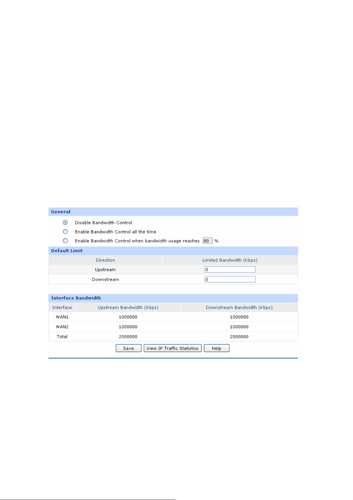
Figure 3-35 Configuration
The following items are displayed on this screen:
General
Disable Bandwidth
Control:
Select this option to disable Bandwidth Control.
-52-
Page 59

Enable Bandwidth
Control all the time:
Enable Bandwidth
Control When:
Default Limit
Limited
Bandwidth:
Interface Bandwidth
Interface:
Select this option to enable Bandwidth Control all the time.
With this option selected, the Bandwidth Control will take effect when the
bandwidth usage reaches the specified value.
Default Limit applies only for users that are not constrained by Bandwidth
Control Rules. These users share certain bandwidth with upper limit
configured here. Value 0 means all the remained bandwidth is available to
use.
splays the current enabled WAN port(s). The Total bandwidth is equal to
Di
the sum of bandwidth of the enabled WAN ports.
Upstream
Bandwidth:
Downstream
Bandwidth:
Note:
● T eam/Downstream Bandhe Upstr width of WAN port you set must not be more than the bandwidth
provided by ISP. Otherwise the Traffic Control will be invalid.
● If there are data flowing into the router from interface A and out from interface B while the
downstream bandwidth of A is dif he smaller one ferent from the upstream bandwidth of B, then t
should be considered as the effective bandwidth, and vice versa.
● Click the <View IP Traffic Statistics> button to jump to IP Traffic Statistics page.
Displays
Upstream
Displays
Downstre n WAN page.
the bandwidth of each WAN port for transmitting data. The
Bandwidth of WAN port can be configured on WAN page.
the bandwidth of each WAN port for receiving data. The
am Bandwidth of WAN port can be configured o
3.3.2.2
On th the Ba
is page, you can configure
Choos u Advanced→Traffic Control→Bandwidth Control to load the following page.
Bandwidth Control
e the men
ndwidth Control function.
-53-
Page 60
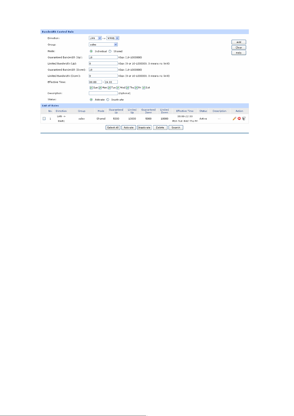
Figure 3-36 Bandwidth Control
The following items are displayed on this screen:
Bandwidth Control Rule
Direction:
Group:
Mode:
Guaranteed Bandwidth (Up):
Select the data stream direction for the entry. The direction of
arrowhead indicates the data stream direction The DMZ port
displays in the drop-down list only when the DMZ port is
enabled. WAN-ALL means all WAN ports through which the data
flow might pass. Individual WAN port cannot be selected if
WAN-ALL rules are added.
Select the group to define the controlled users.
Individual: The bandwidth of each user equals to the current
bandwidth of this entry.
Shared: The total bandwidth of all controlled IP addresses
equals to the current bandwid
Specify the Guaranteed Upstream Bandwidth for this entry
th of this entry.
.
Limited Bandwidth (Up):
Guaranteed Bandwidth
(Down):
Limited Bandwidth (Down):
Specify the Limited Upstream Bandwidth for this entry.
Specify the Guaranteed Downstream Bandwidth for this entry.
Specify the Limited Downstream Bandwidth for this entry.
-54-
Page 61

Effective Time:
Description:
Status:
List of Rules
You can view the information of the entries and edit them by the Action buttons.
The first entry in Figure 3-36 indicates: The users within group
the Downstream/Upstream Guaranteed Bandwidth is 5000kbps, while the Downstream/Upstream
Limited bandwidth is 10000kbps. This entry takes effect at 8 a.m. to 10 p.m. from Mond y to
Friday.
Note:
● The premise for single rule taking effect is that the bandwidth of the interface for this rule is
Specify the time for the entry to take effect.
Give a description for the entry.
Activate or inactivate the entry.
“sales” share the bandwidth and
a
s ed uufficient and not us p.
● It is impossible to satisfy idth if the total guaranteed bandwidth specified all the guaranteed bandw
by all Bandwidth Control rules for certain interface exceeds the physical bandwidth of this
interface.
● When DMZ port is disabled, it is only allowed deleting operation to the related rules.
3.3.3 Session Limit
The a UD nite. If some local hosts transmit
mount of TCP and P sessions supported by the router is fi
too many TCP and UDP sessions to the public network, the communication quality of the other local
hosts will be thus it is necessary to limit th s.
3.3.3 ssion Limit
.1 Se
On this page, you can configure the session limit to specified PCs.
Choose the
affected, e sessions of those host
menu Advanced
→Session Limit→Session Limit to load the following page.
-55-
Page 62
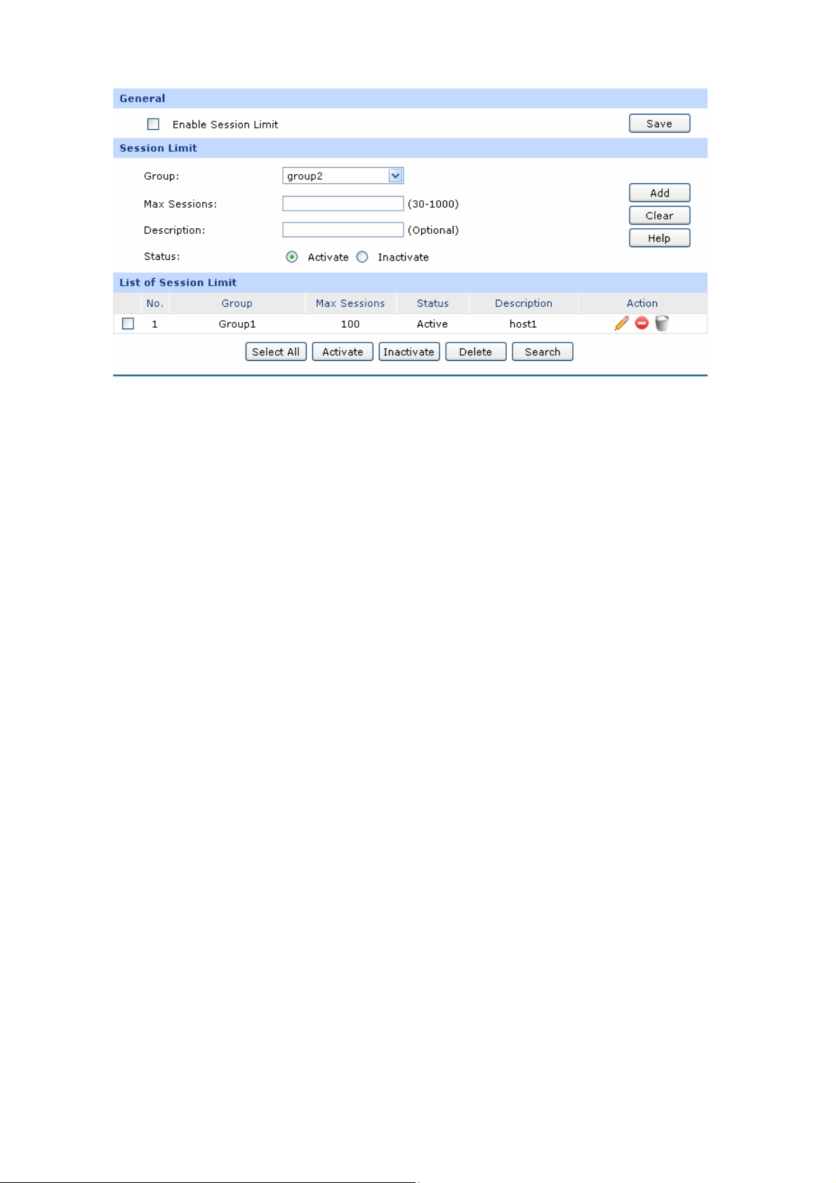
Figure 3-37 Session Limit
The followin
General
Session Limit
g items are displayed on this screen:
Enable Session
Limit:
Group:
Max. Sessions:
Description:
Status:
Check here to enable Session Limit, otherwise all the Session Limit
entries will be disabled.
Select a group to define the controlled users.
Enter the max. Sessions for the users.
Give a description for the entry.
Activate or
inactivate the entry.
List of Session Limit
You can view the information of the entries and edit them by the Action buttons.
The first entry in Figure 3-37 indicates: The amount of maximum sessions for the hosts within
grou
p1 is 100 and this entr
y is enabled.
3.3.3.2 Session List
On this page, you can view the Session Limit information of hosts configured with Session Lim
Choose the menu Advanced→Session Limit→Session List to load the following page.
-56-
it.
Page 63
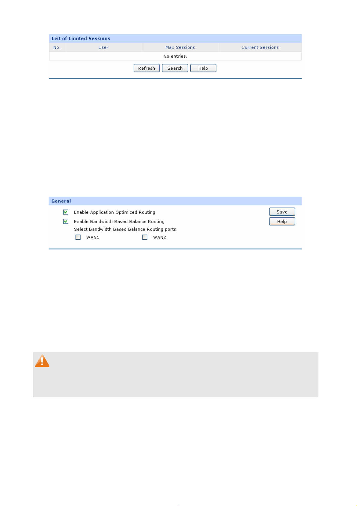
Figure 3-38 Session List
In this table, you can view the session limit information of users configured with Session Limit. Click
the <Refresh> button to get the latest information.
3.3.4 Load Balance
In this part, you can configure the traffic sharing mode of the WAN ports to optimize the resource
utilization.
3.3.4.1 Configuration
onfiguration to load the following page. Choose the menu Advanced→Load Balance→C
Figure 3-39 Configuration
With re Enable
the box befo Application Optimized Routing checked, the router will consider the
source IP address and destin ss of the packets as a whole and record the WAN port they
pass through. And then the packets with the same source IP address and destination IP address or
destination port will be forwarded to
multi-connected applications
Check the box before Enable Bandwidth Based Balance Routing and select the WAN port below,
Load Balance of the specified WAN port will be enabled automatically if no routing rules are set.
Then click th tton to apply
The W ectinAN ports not conn g to the Internet don’t support Intelligent Balance, please do not select
them.
e <Save> bu .
Note:
ation IP addre
the recorded WAN port. This feature is to ensure the
to work properly.
3.3.4.2 Policy Routing
Policy Routing provides an the policy defined by the
netwo .
rk administrator
accurate way to control the routing based on
Choos nced e following page.
e the menu Adva →Load Balance→Policy Routing to load th
-57-
Page 64
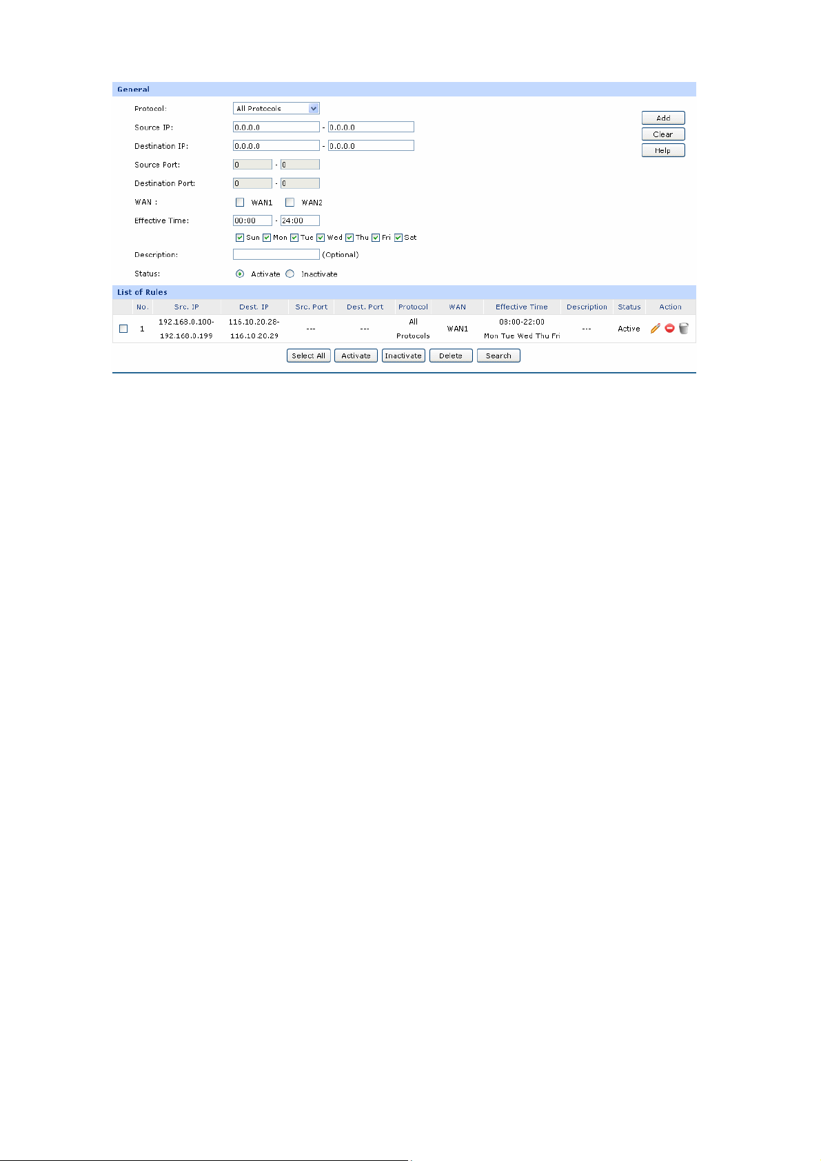
Figure 3-40 Policy Routing
The followin
g items are displayed on this screen:
General
Protocol:
Select the protocol for the entry in the drop-down list. If the protocol you
want to set is not in the list, you can add it to the list on 3.3.4.4 Protocol
age.
p
Source IP:
Enter the source IP range for the entry. 0.0.0.0 - 0.0.0.0 means any IP is
acceptable.
Destination IP:
Enter the destination IP range for the entry. 0.0.0.0 - 0.0.0.0 means any
IP is acceptable.
Source Port:
Enter the source Port range for the entry, which is effective only when the
protocol is TCP, UDP or TCP/UDP. The default value is 1 – 65535, which
means any port is acceptable.
Destination Port:
WAN :
Effective Time:
Enter the destination port range for the entry, which is effective only when
the protocol is TCP, UDP or TCP/UDP. The default value is 1 – 65535,
which means any port is acceptable.
e W
Select th g packets.
AN port for transmittin
Specify the time for the entry to take effect.
-58-
Page 65
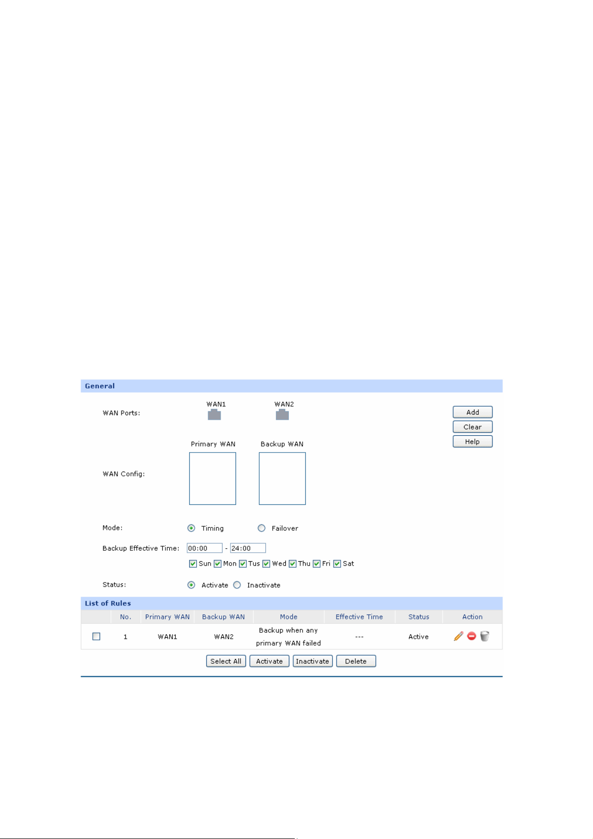
ate or inactivate the entry
Status:
List of Rules
You can view the informati
The first entry in Figure 3-40 indicates: All the packets with Source IP
92.16
1 d Destina
WAN1 port, regardless of ffect at 8
am to 10 pm from Monday to Friday.
3.3.4 nk Backup
With Link Backup function, the
to another to keep an always o
On this page, you can configur
burden of WAN port and improv
Choose the menu Advanced→Load Balance→Link Backup to load the following page.
8.0.199 an tion IP between 116.10.20.28 and 116.10.20.29 will be forwarded from
.3 Li
Activ
on of the entries and edit them by the Action buttons.
the port and protocol. This entry is activated d and will take e
router will switch all the new sessions from dropped line automatically
n-line network.
e the Link Backup function based on actual need to reduce the traffic
e the network efficiency.
.
between 192.168.0.100 and
Figure 3-41 Link Backup
The following items are displayed on this screen:
-59-
Page 66

General
WAN Ports:
WAN Config:
Mode:
Timing:
Displays all the WAN ports in use. You can drag the light-blue WAN
button to primary and backup WA list. The color of W
changing to gray indicates that the WAN port is alread
N AN button
y in the primary
and backup WAN list.
The WAN port in the secondary WAN list will share the traffic for the
WAN in the primary WAN list under the specified condition.
You can select Timing or Failover Mode.
Link Backup will be enabled if the specified effective time is reached. All
the traffic on the primary WAN will switch to the backup WAN at the
beginning of the effective time; the traffic on the backup WAN will switch
to the primary WAN at the ending of the effective time.
Failover:
Backup Effective
Time:
Specify the premise for Failover Mode. The backup WAN port will be
enabled is met.
Specify the backup
only when the premise
effective time if Timing Mode has been selected.
Then the backup WAN port will be enabled, while the primary WAN port
is disabled in the specified time period. When the start time you enter is
not earlier than the end time, the default effectiv
time of the day to the end time of the next day.
Status: Activate or inactivate the entry.
List of Rules
You can view the information of the entries and edit them by the Action buttons.
The first entry in
AN2 will be enabled while WAN1 is failed. This entry is enabled.
W
Figure 3-41 indicates: WAN1 is the primary po
rt and WAN2 is the backup port.
e time is from the start
Note:
The same WAN port cannot be added to the primary and secondary WAN lists at the same time, and
one WAN port should be added to only one list.
-60-
Page 67
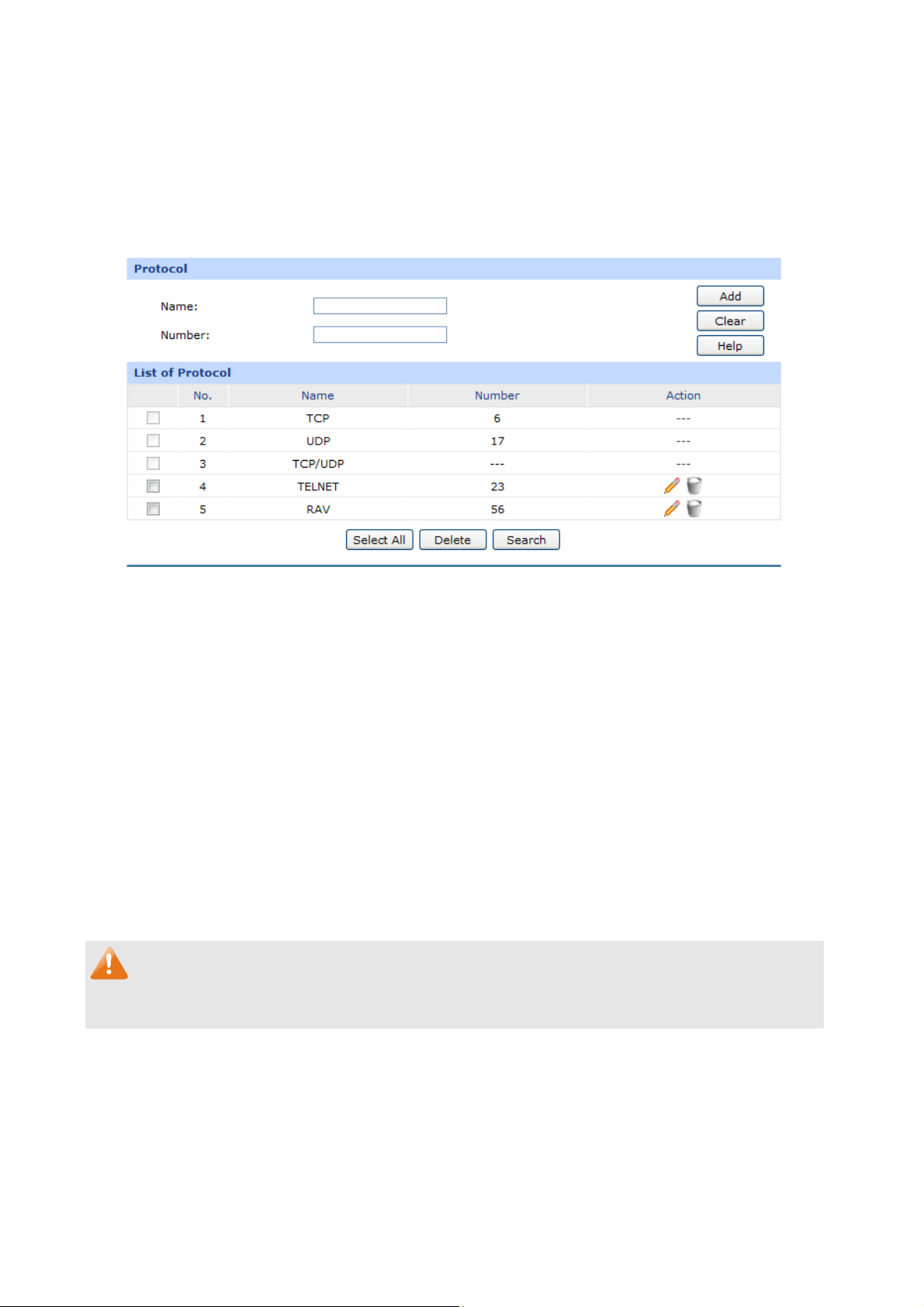
3.3.4.4 Protocol
On this page, you can specify the protocol for routing rules conveniently. A protocol constitutes of the
name and number. The router predefines three commonly used pr
TCP/UDP. Moreover, you can also add new protocols as your wish.
Choose the menu Advanced→Load Balance→Protocol to load the following page.
Figure 3-42 Protocol
otocols such as TCP, UDP and
The following items are displayed on this screen:
Protocol
Name:
Number:
L ol
ist of Protoc
You can view the inform ntries and edit them by the Action buttons.
Note:
The system predefined proto nnot be configured.
Enter a name to indicate a protocol. The na
drop-down list of Protocol on Access Rule page.
Enter the Number of the protocol in the range of 0-255.
ation of the e
cols ca
3.3.5 Routing
me will display in the
3.3.5.1 Static Route
Routin process of s twork along which to send network traffic.
Static Route is a kind of special routing configured by the administrator, which is simple, efficient, and
reliable.
g is the electing optimized paths in a ne
-61-
Page 68
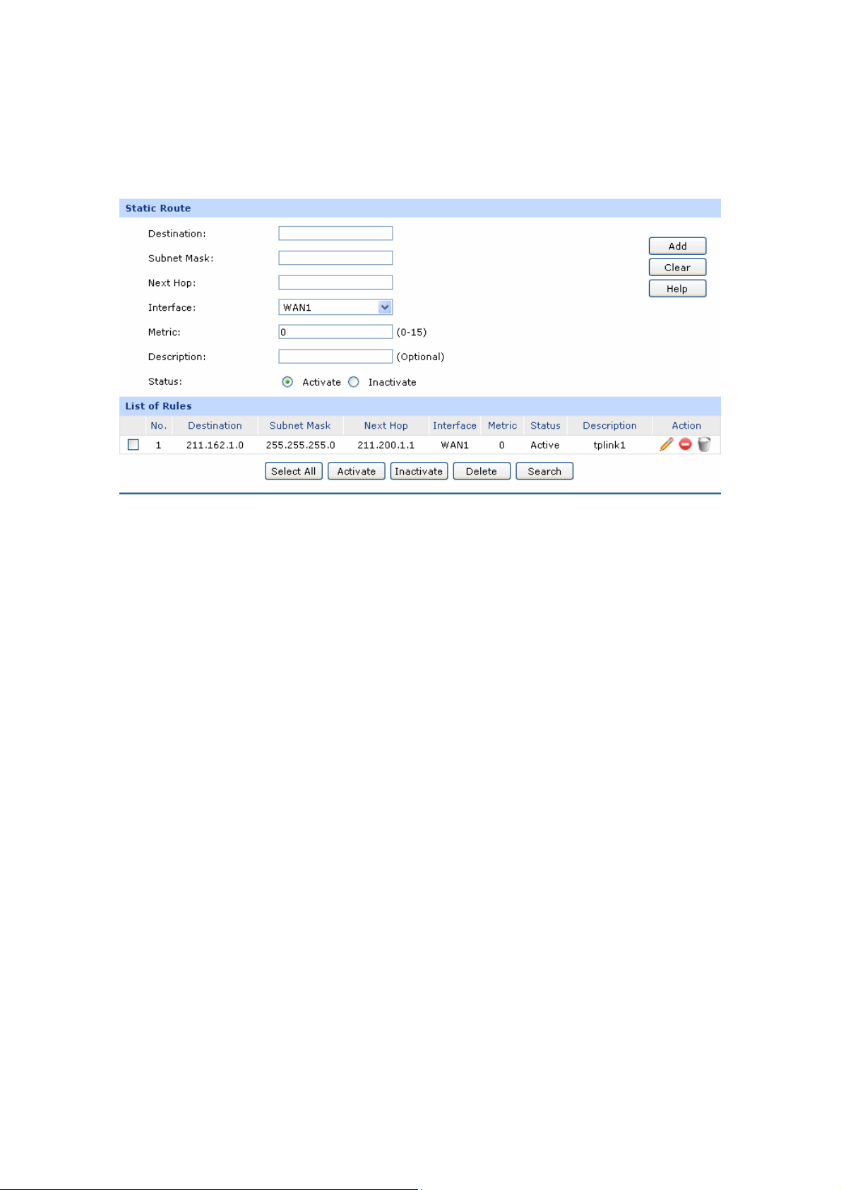
Commonly used in sized network with fixed
the oute information
network topology automatically. The administrator should modify the static r
small- topology, Static Route does not change along with
manually as long as the network topology or link status is changed.
Cho
ose the menu Advanced→Routing→Static Route to load the following page.
Figure 3-43 Static Route
The following items are displayed on this screen:
Static Route
Destination:
Subnet Mask:
Next Hop:
Interface:
Enter the destination host the route leads to.
Enter the Subnet Mask of the destination network.
Enter the gateway IP address to which the packet should be sent next.
Select the physical network interface, through which this route is
accessible.
Metric:
Defines the priority of the route. T
priority is. The default value is 0. It is recommended to keep the default
value.
he smaller the value is, the higher the
Description:
Status:
Give a description for the entry.
Activate or inactivate the entry.
-62-
Page 69
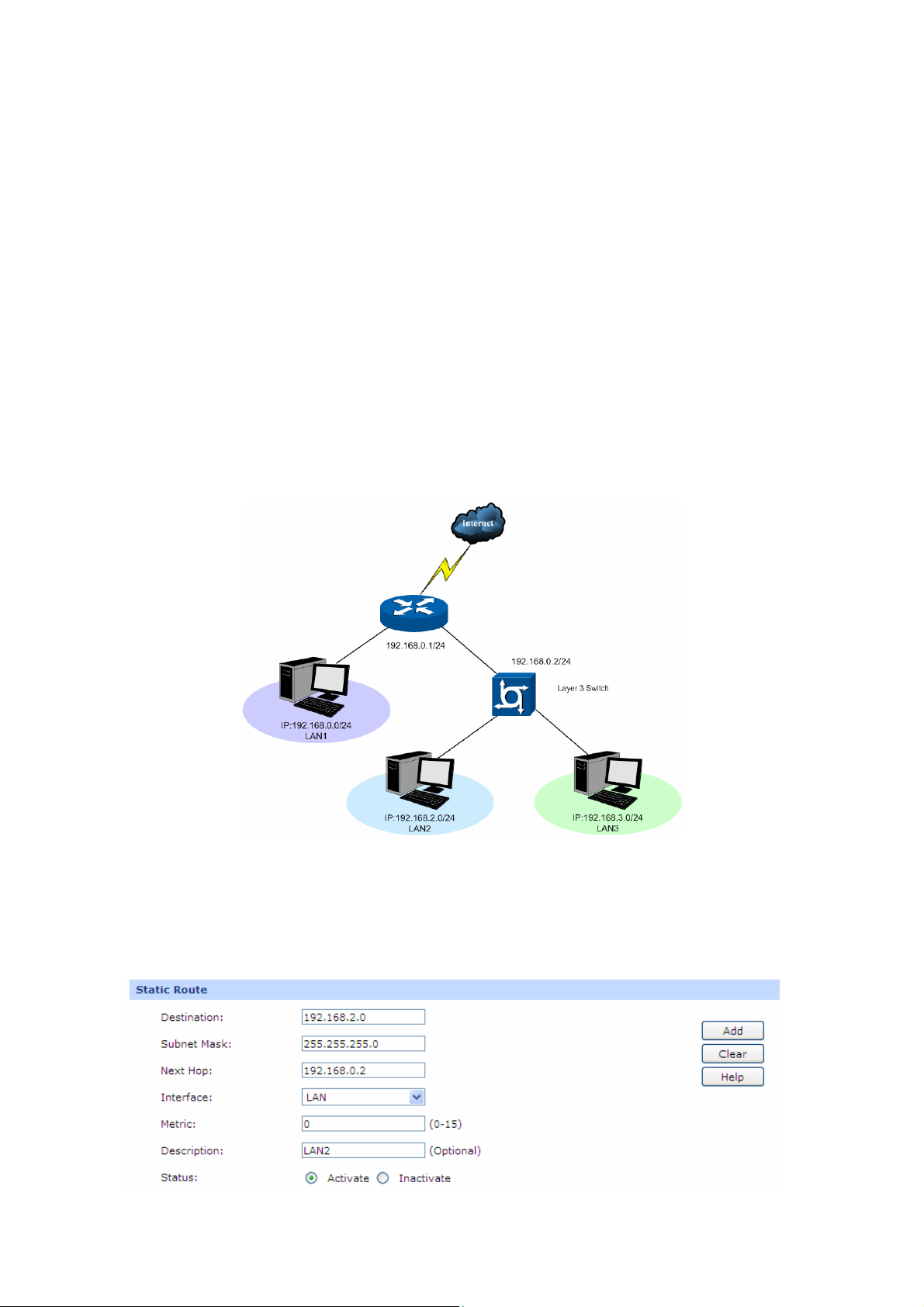
List of Rules
You can view the information of the entries and edit them
e Action buttons.
by th
The first entry in Figure 3-43 indicates: If there are packets being sent to a device with IP address
of 21
1.162.1.0 and subnet mask of 255.255.255.0, the router will forward the packets from WAN1
port to the next hop of 211.200.1.1.
Application Examp
Net
work Requirements
le
LAN1 is under the router and it uses network segment 192.168.0.0 /24. LAN2 and LAN3 are under a
layer 3 switch and they use network segments 192.168.2.0 /24 and 192.168.3.0 /24 respectively. The IP
address of the cascading LAN port between the layer 3 switch and the router is 192.168.0.2. Now the
hosts within LAN1 desire to access the hosts within LAN2 and LAN3.
The network topology is shown as the following:
Configuration procedure
1. On the Static Route page, add a static routing rule for LAN2 with destination address 192.168.2.0
(LAN2’s IP address) and next hop address 192.168.0.2 (IP address of the cascading LAN port) as
shown in the following figure. Then click the <Add> button.
-63-
Page 70
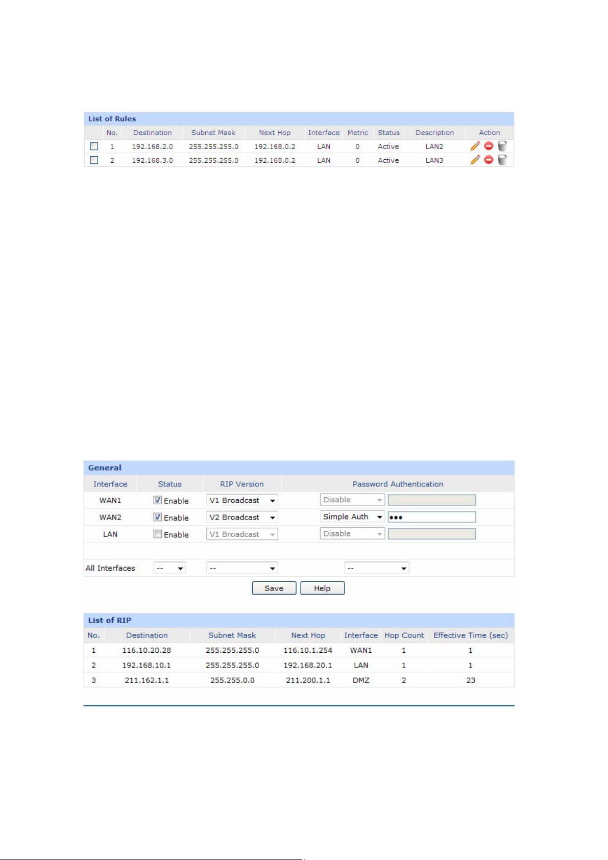
2. Add a static routing rule for LAN3 by referring to
The static routing rules are shown in the following figure.
3.3.5
.2 RIP
RIP (Routing Information Protocol) is a dynamic route protocol using distance vector algorithm to select
the op ith fe
timal path. W
in small and
The distance of RIP refers to the hop counts that a data packet passes through before reaching its
destination, the value range of which is 1–15. It means the destination cannot be reached if the value is
more l
than 15. Optima path indicates the path with the fewest hop counts. RIP exchanges the route
information every 30 sec n
in 180 seconds, the RIP of the other routers would set the distance to this router into infinity and delete
the corresponding information from route table.
RIP develops fro tial R P 1
iable Length Subnet Mask), simple plain text authentication, MD5 cryptograph authentication, CIDR
(Var
(Classless Inter-Domain
medium-sized networks
atures of easy configuration, management and implementation, it is widely used
such as the campus network.
onds by broadcasting UDP packets. If one router has not sent route informatio
m ini I v to RIPv2 gradually. Compared with RIPv1, RIPv2 supports VLSM
Routing) and multicast.
step 2.
TL-ER6120 supports both RIPv1 version and RIPv2 version, thus you can configure the RIP version
d on the actual need to improve the network performance.
base
ose the menu Advanced→Routing→RIP to load the following page.
Cho
Figure 3-44 RIP
The following items are displayed on this screen:
-64-
Page 71

General
Interface:
Status:
RIP Version:
Password
Authenticati
All Interface
ist of RIP
L
After RIP is enabled, the information of RIP forwarding the packets received by the router will be
displayed in the list.
Displays the interfaces which has been physically connected or assigned
static IP.
Enable or disable RIP protocol.
Select RIPv1 or RIPv2. RIPv2 supports multicast and broadcast.
If RIPv2 is enabled, set the Password Authentication according to the actual
network situation, and the
on:
Here you can operate all the interfaces in bulk. All the interfaces will not apply
s:
RIP if “Enable” option for selected.
password should not be more than 15 characters.
All Interfaces is
The first entry in Figure 3-44 indicates: when receivi
the router will select WAN1 e destination IP as next hop and
forward data via this port. The IP address of next hop is 116.10.1.254 and the hop count is 1. The
ffective time of this en 1 second.
e try is
Note:
● RIP function cannot be set if the router is in NAT Mode. To set RIP function, please change the
System Mode to Routing or Full Mode.
● The RIP function of WAN port takes effects only when the Connection Type of this WAN port is
Static IP.
which is in the same network with th
ng packets with destination IP is 116.10.20.28,
3.3.5.3 Route Table
This page displays the information of the system route table.
Choose the menu Advanced→Routing→Route Table to load the following page.
-65-
Page 72

Figure 3-45 RIP
The following items are displayed on this screen:
Route Table
Destination:
Gateway:
Flags:
Logical Interface:
Physical Interface:
Metric
3.4
Firewall
3.4
.1 Anti ARP Spoofing
The Destination of route entry.
The Gateway of route entry.
The Flags of route entry. The Flags describe certain characteristics of
the route.
The logical interface of route entry.
The y.
physical interface of r
The Metric of route entry.
oute entr
ARP
(Address Resolution Protocol) is used for analyzing and mapping IP addresses to the
corresponding MAC addresses so that packets can be delivered to their destinations correctly.
ARP ddress and maintain an ARP
functions to translate the IP address into the corresponding MAC a
Table in which the latest used IP address-to-MAC address mapping entries are stored. ARP protocol
can facilitate the Hosts in the same n
external network via Gateway. However, since ARP protocol is implemented with the premise that all
osts and Gat trusted, there are high security ri
the H eways are sks during ARP Implementation
Procedure in the actual complex network.
The attacker may send the ARP spoofing packets with false IP address-to-MAC address mapping
entries, and then the device will automatically update the ARP table after receiving wrong ARP
etwork segment to communicate with one another or access to
-66-
Page 73
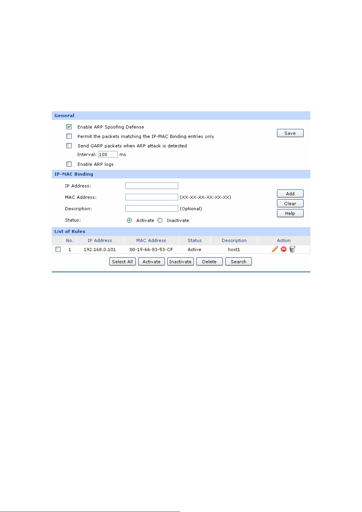
packets, which results in a breakd y is
generated to
3.4.1. MAC Binding
IP-MAC Binding functions to bind the IP address, MAC address of the host together and only allows the
Hosts matching the boun
Choose the age.
1 IP-
d entries to access the network.
menu Firewall→Anti ARP Spoofing→IP-MAC Binding to load the following p
own of the norma
kind of attack. prevent the network from this
l communication. Thus, ARP defense technolog
Figure 3-46 IP-MAC Binding
The following items are displayed on this screen:
General
It is recommended to check all the options. You should import the IP and MAC address of the host to
IP-MAC Binding List and enable the corresponding entry before enabling “Permit the packets
matching the IP-MAC Binding entries only”.
When suffered ARP attack, the correct ARP information will be sent to the device suffering attack
initiatively by GARP (Gratuitous ARP) packets, thus the error ARP information of the device will be
replaced. You can set the packets sending rate in the Interval field.
With the box before Enable ARP will send ARP logs to the specified
server. The IP address of server is the Server IP 3.7.7 Logs.
IP-MAC Binding
Address:
IP
Logs checked, the router
set on
Enter the IP Address to be bound.
MAC Address:
Enter the MAC Address corresponding to the IP Ad
-67-
dress.
Page 74
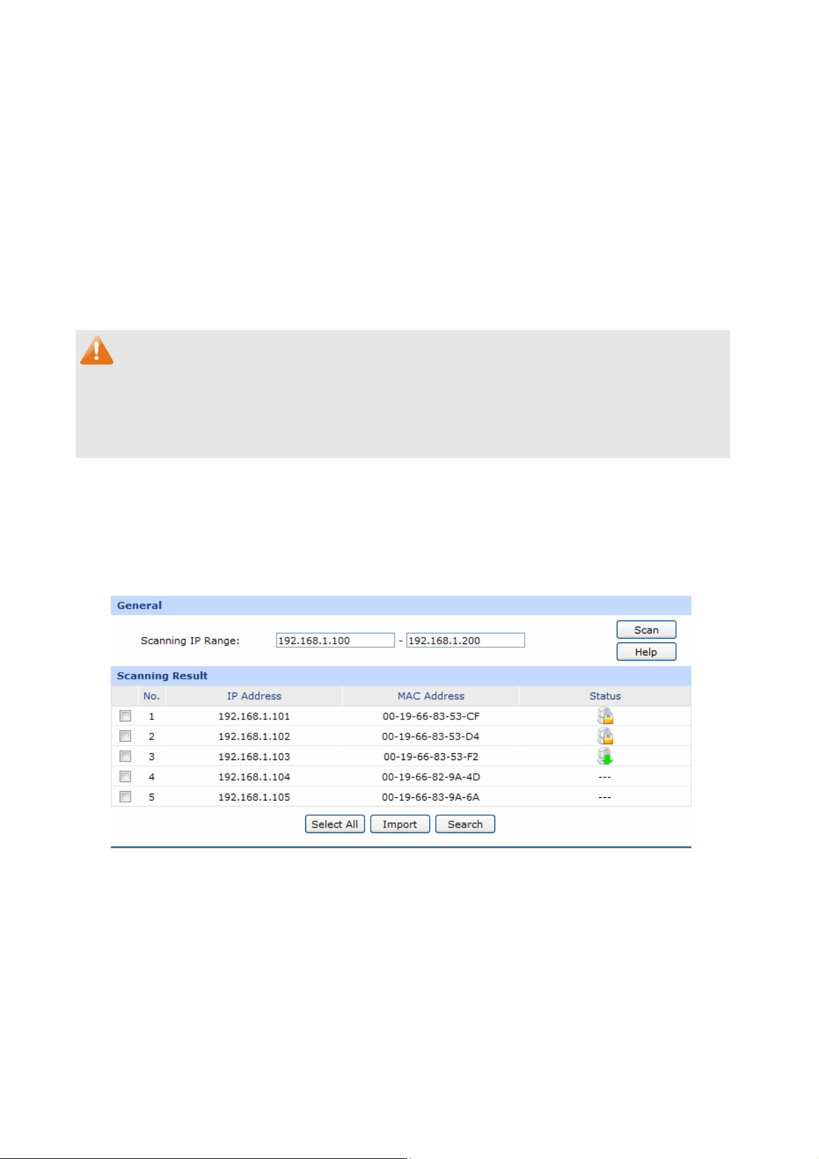
cription
Des :
Status:
List of Rules
You an view t
c he information of the entries and edit them by the Action buttons.
The first entry in Figure 3-46 indicates: The IP address of 192.168.1.101 and MAC address of
9-66-83-53-CF have been bound and this entry is activated.
00-1
Note:
If all the entries in the binding list are disabled and “Permit the packets of IP-MAC Binding entries only”
option is selected and saved, the WEB management page of the router cannot be login. At the
moment, you should restore the router to factory default and login again.
3.4.1.2 ARP Scan
ning
Give a description for the entry.
Activate or inactivate the entry.
ARP Scanning feature enables the router to scan the IP address and corresponding MAC address and
display them on the List o
Choose the menu Firewall→Anti ARP Spoofing→ARP Scanning to load the following p
Enter the start and the end IP addresses into the Scanning IP Range field. Then click the <Scan>
f Scanning Result.
age.
Figure 3-47 ARP Scanning
button, the router will scan all the
list.
The entries displayed on the List of Scanning Result do not mean the IP and M
already bound. The current status for the entry will display in the “Status” field.
active hosts within the scanning range and display the result in the
-68-
AC addresses are
Page 75
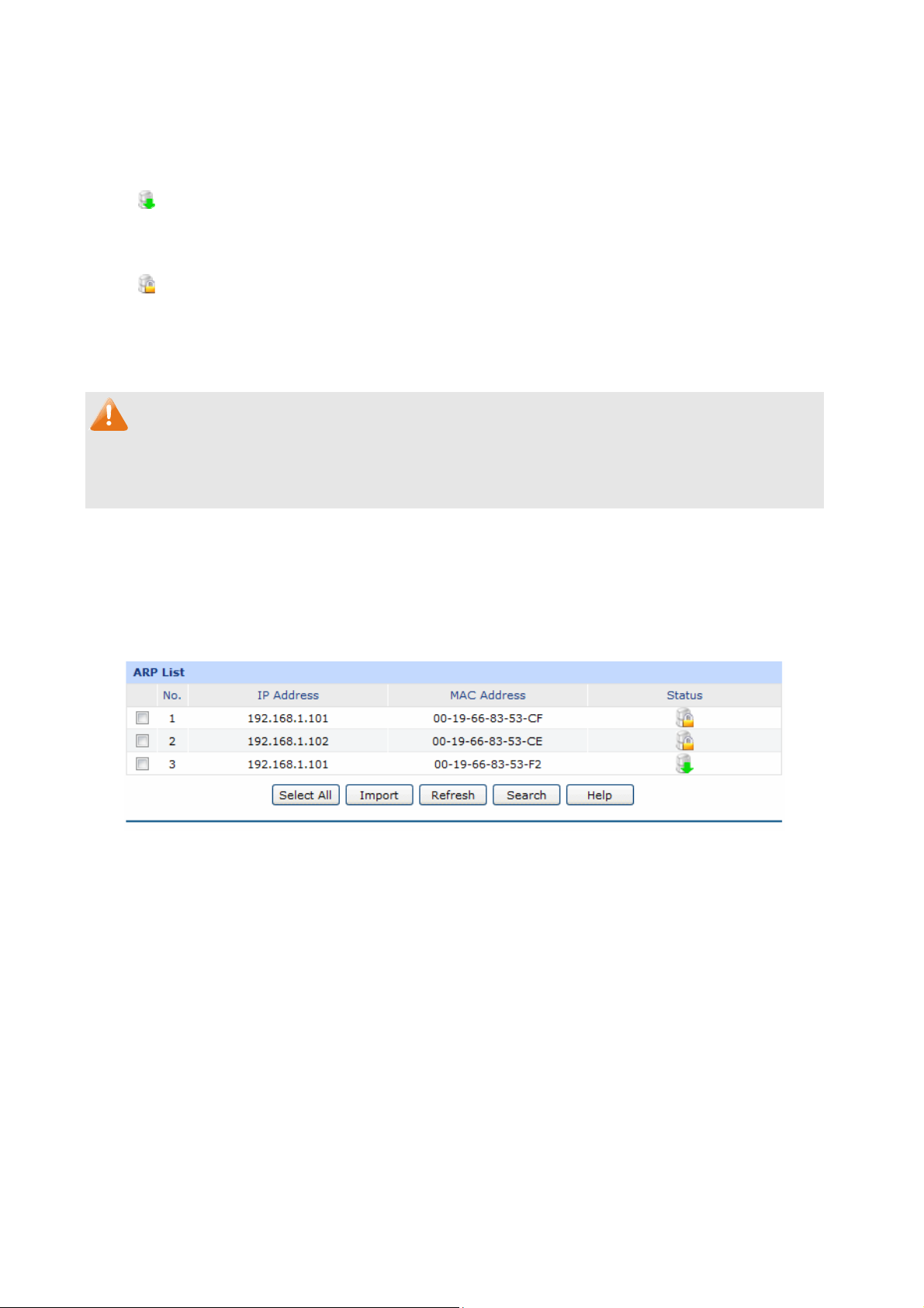
--- Indicates that the IP and MAC address of this entry are not bound and may be
replaced by error ARP information.
To bind the entries in the list, check these entries and click the <Import> button, then the settings will
take effect if the entries do not conflict with the existed entries.
Note:
If the local hosts suffered from ARP attack, you cannot add IP-MAC Binding entries on this page.
Please add entries manually on 3.4.1.1 IP-MAC Binding.
Indicates that this entry is imported to the list on IP-MAC Binding page, but not
effective yet.
Indicates that the IP and MAC address of this entry are already bound.
3.4.1.3 ARP List
On this page, the IP-MAC information of the hosts which communicated with the router recently will be
saved in the ARP list.
Choose the menu Firewall→Anti ARP Spoofing→ARP List to load the following page.
Figure 3-48 ARP List
The configur
ARP Scanning p
The unbound IP-MAC informatio
removed from the list if it has no
regarded as the aging time of th
ations for the entries is the same as the
age.
n will be replaced by new IP-MAC information or be aut
t been communicated with others for a long time. This period is
e ARP information.
configuration of List of Scanning Result on 3.4.1.2
omatically
3.4.2 Attack Defense
With A se function e ackets and prevent
the port scanning from external network, so as to guarantee the network security.
Choos wall→Att
ttack Defen nable
e the menu Fire ack Defense→Attack Defense to load the following page.
d, the router can distinguish the malicious p
-69-
Page 76
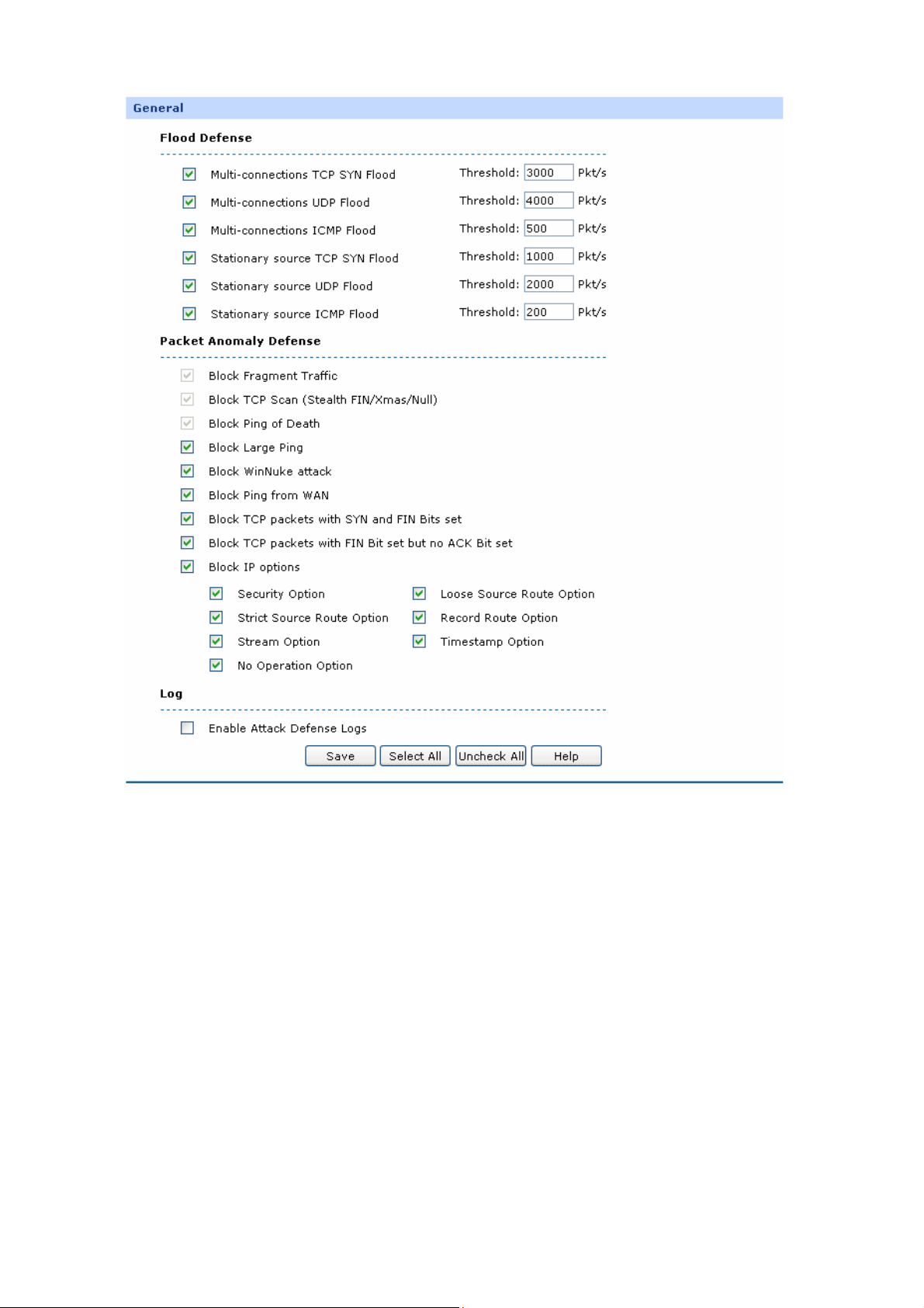
Figure 3-49 Attack Defense
llowing items are on this screen:
The fo displayed
General
Flood Defense:
Flood attack is a commonly used DoS (Denial of Service) attack,
in
cluding TCP SYN, UDP, ICMP and so on. It is recommended to
select all th
e Flood Defense options and specify the corresponding
thresholds. Keep the default settings if you are not su
Packet Anomaly
Defense:
Enable Attack
Packet Ano
select all the Packet Anomaly Defense options.
With this box checked, the router will record the defense logs.
maly refers to the abnormal packets. It is recommended to
Defense Logs:
re.
-70-
Page 77
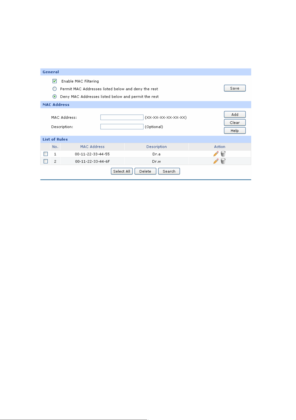
3.4.3 MAC Filtering
On this page, you can control the Internet access of local hosts by specifying their MAC addresses.
Choose the menu Firewall→MAC Filtering→MAC Filtering to load the following page.
Figure 3-50 MAC Filtering
The followin
General
To control the access to Internet for hosts in you private network, it is recommended to check the
box before Enable MAC F lt
MAC Filtering
List of Rules
g items are displayed on t
MAC Address:
Description:
i ering and select a filtering mode according to actual situation.
his screen:
Enter the MAC Address to be filtered.
Give a description for the entry.
You can view the informatio y the Action buttons.
3.4.4 ntrol
Access Co
n of the entries and edit them b
3.4.4.1 URL Filtering
URL (Uniform Resource Locator) specifies where an identified resource is available and the
mechanism for retrieving it. URL Filter functions to filter the Internet URL address, so as to provide a
convenient way for controlling the access to Internet from LAN hosts.
-71-
Page 78
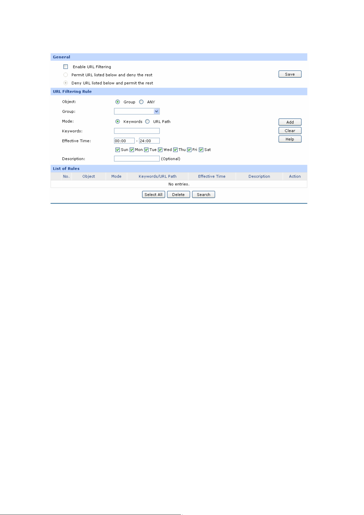
irew → s Control→URL Filtering to load the following page. Choose the menu F all Acces
Figure 3-51 URL Filtering
The following items are displayed on this screen:
General
To control the access to Internet for hosts in your private network, you are recommended to check
the box before Enable URL Filtering and select a filtering rule based on the actual situation.
URL Filtering Rule
Object:
Mode:
Select the range in which the URL Filtering takes effect:
ANY: URL Filtering will take effect to all the users.
Group: URL Filtering will take effect to all the users in group
Select the mode for URL Filtering. “Keyword’’ indicates that all the URL
addresses including the sp
ecified keywords will be filtered. “URL Path”
.
Effective Time:
Description:
indicates that the URL address will be filtered only whe
matches the specified URL.
Specify the time for the entry to take effect.
Give a
description for the entry.
-72-
n it exactly
Page 79
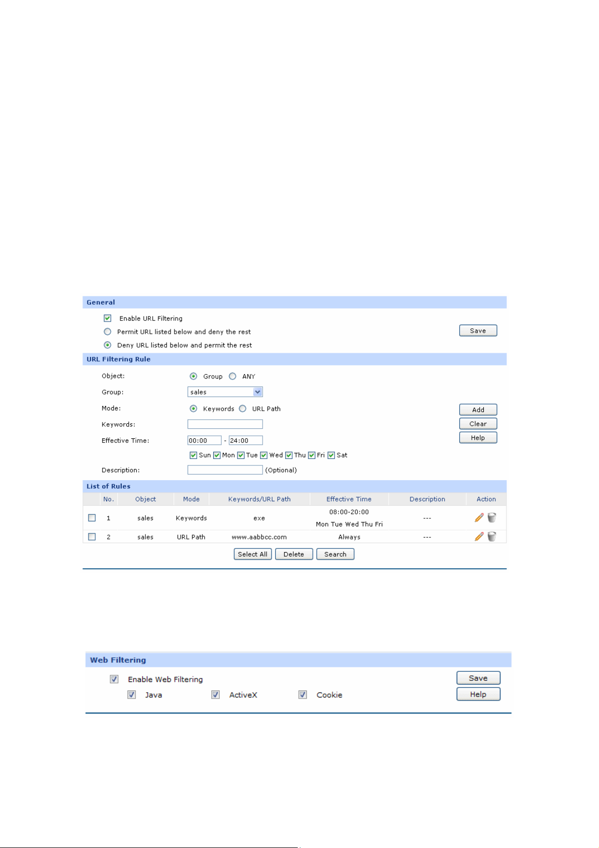
List of Rules
You can view the information of the entries and edit them by the Action buttons.
Application Example:
Network Requirements:
Prevent the local hosts from accessing Internet website www.aabbcc.com anytime and downloading
the files with suffix of “exe” at 8:00-20:00 from Monday to Friday.
Configuration Procedure:
Select Keywords mode and type ”exe“ in the field, select URL mode and type “www.aabbcc.com” as
the following figure shows, then specify the effective time and click the <Add> button to make the
setting take effect.
3.4.4.2 Web Filtering
On thi u can filter the d
s page, yo esired web components.
Choose the menu Firewall→Ac
cess Control→Web Filtering to load the following page.
Figure 3-52 Web Filtering
eb Filtering and select the web components toCheck the box before Enable W be filtered.
-73-
Page 80
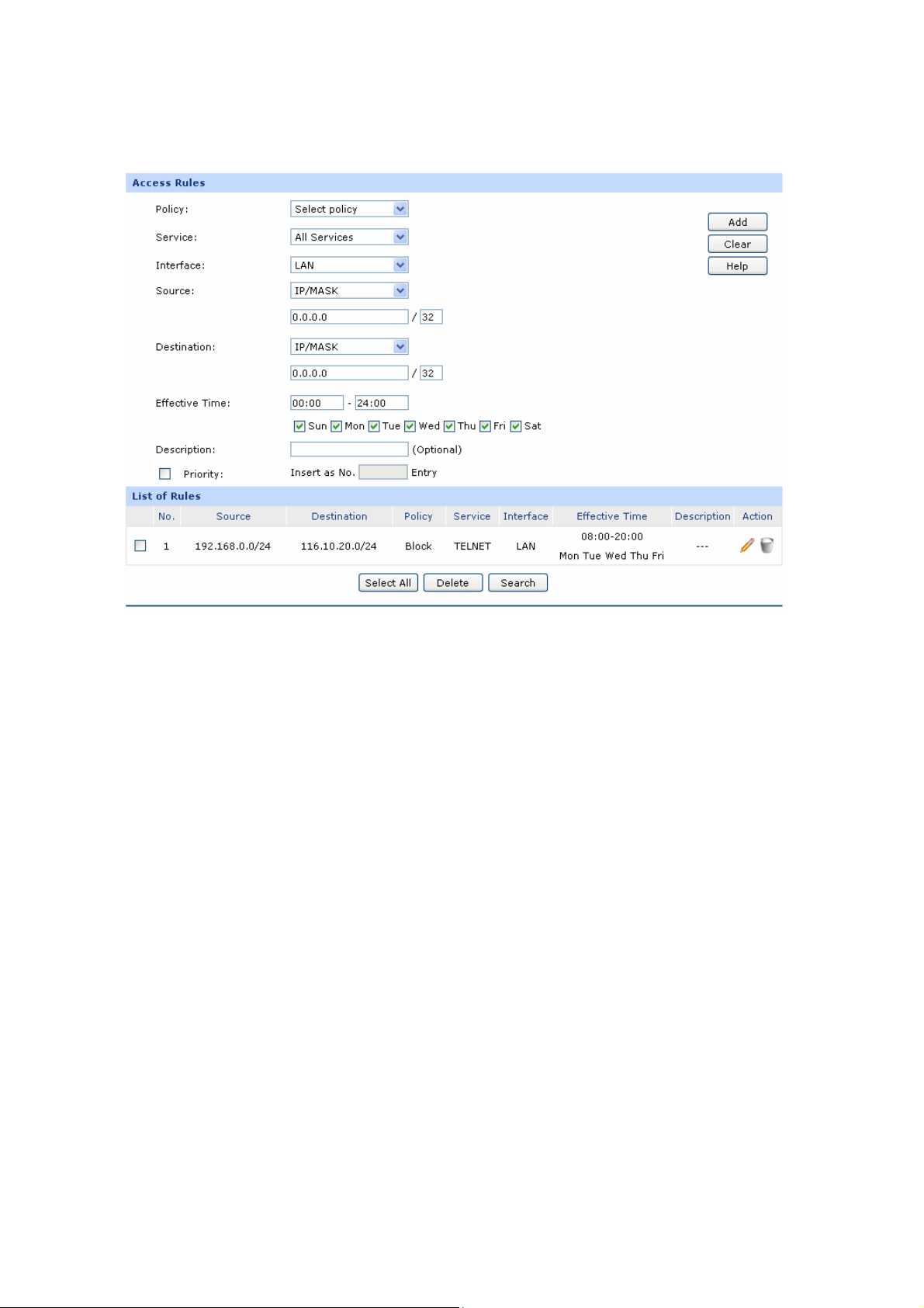
3.4.4.3 les
Choose the menu Firewall→Ac l→Access Rules to load the following page.
Access Ru
cess Contro
The fo s are displaye
Access Rules
g item d on this screen:
llowin
Policy:
Service:
Figure 3-53 Access Rule
Select a policy for the entry:
Block: When this option is selected, the packets obeyed the rule
l not be permitted to pass through the router.
wil
Allow: When this option is selected, the packets obeyed the rule
will be allowed to pass through the router.
Select the service for the entry. Only the service belonging to the
specified service type is limited by the entry. For example, if you select
“Block” for Policy and only FTP for Service, the packets of other service
Interface
types can still pass through the router. You can add new service types
on 3.4.4.4 Service.
:
Select interface for the entry. The entry will take effect when the
interface to which the data is flowing is selected. WAN, LAN or DMZ
refers to all the WAN, LAN or DMZ interfaces.
-74-
Page 81

Source:
Destination:
Select
three way
the Source IP Range for the entries, including the following
s:
IP/MASK: Enter an IP address or subnet mask. ("0.0.0.0/32"
means any IP).
Group: Select a predefined group of users. You
can set the group
on3.2.1 Group.
ANY: means for any users.
Select the Destination IP Range for the entries, including the following
two ways:
IP/MASK: Enter an IP address or subnet mask. ("0.0.0.0/32"
means any IP is acceptable).
ANY: means for any users.
Effective Time:
Description:
Priority:
Specify the time for the entry to take effect.
Give a description for the entry.
Select this option to specify the priority for the added entries. The latest
enabled entry will be displayed at the end of the list by default.
List of Rules
Y
ou can view the information of the entries and
edit them by the Action buttons. The smaller the
value is, the higher the priority is.
The first entry in Figure 3-53 indicates: The TELNET packets transmitted from the hosts within the
network of 192.168.0.0/24
uesday to Saturday.
T
will be not allowed to p
ass through the router at 8:00-20:00 from
Note:
● For the users in the private n le, the default Policy is Allow. etwork and not being set access ru
● To specify all IP addresses, type “0.0.0.0 / 32” in the Policy field.
● For det subnet mask, pailed setting of lease refer to Appendix B FAQ.
-75-
Page 82
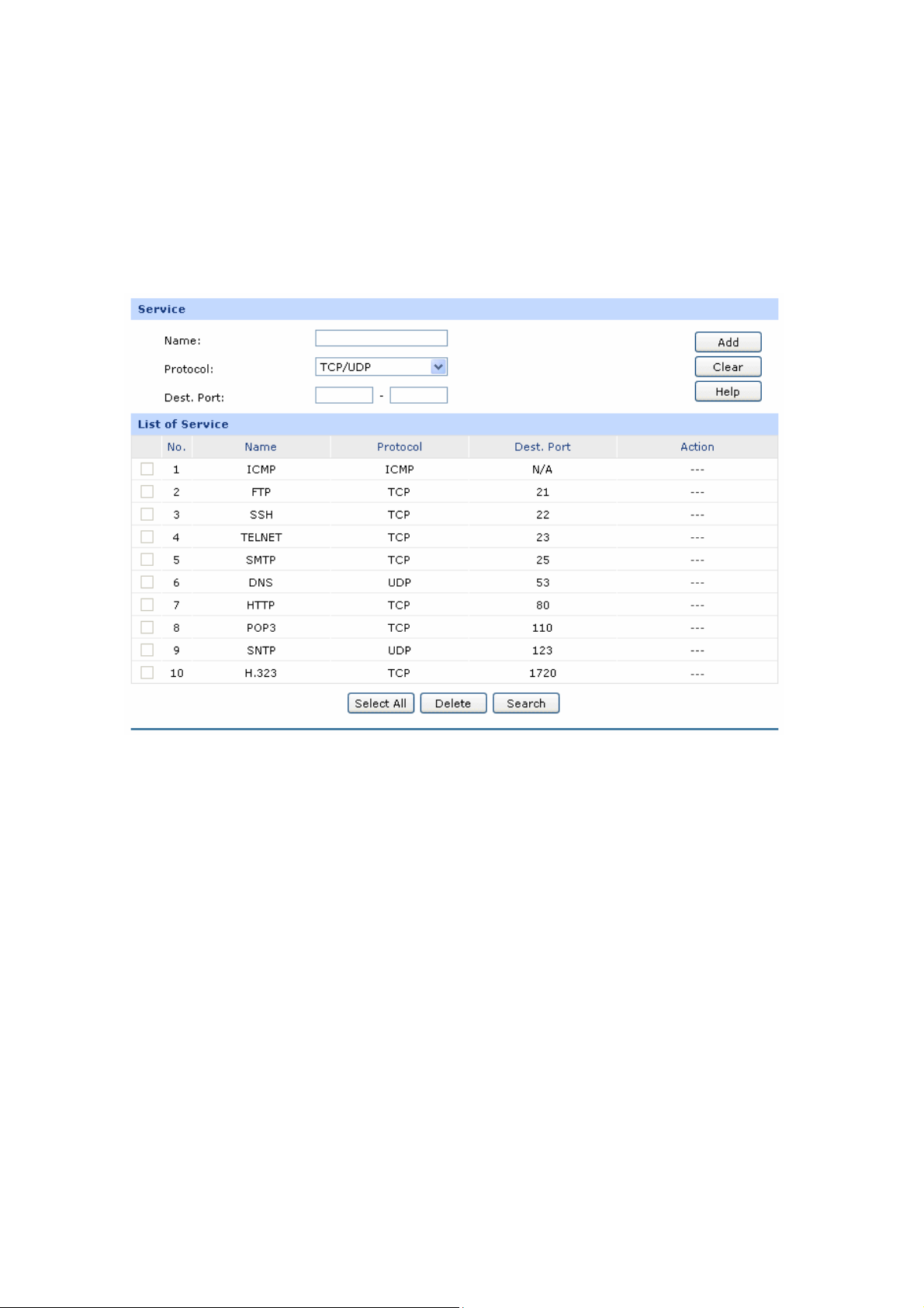
3.4.4.4 Service
The ered for Firewall
Service function allows you to specify the protocol and port number to be filt
function conveniently. Protocol name and port range constitute a service type. The router predefines
three commonly used services such as HTTP, FTP and TELNET and you can also add customized
services if needed.
Choose the menu Firewall→Access Control→Service to load the following page.
Figure 3-54 Service
The following items are displayed on this screen:
Service
Ent name should not be more than 28
Name:
Protocol:
Dest. Port:
er a name for the service. The
characters. The n
Access Rule page.
Select the protocol for the service. The system predefined protocols
include TCP, UDP and TCP/UDP.
Enter the start and end ports to make a destination port range for the
service. The start port number cannot be greater than the end port
number.
ame will display in the drop-down list of Protocol on
-76-
Page 83
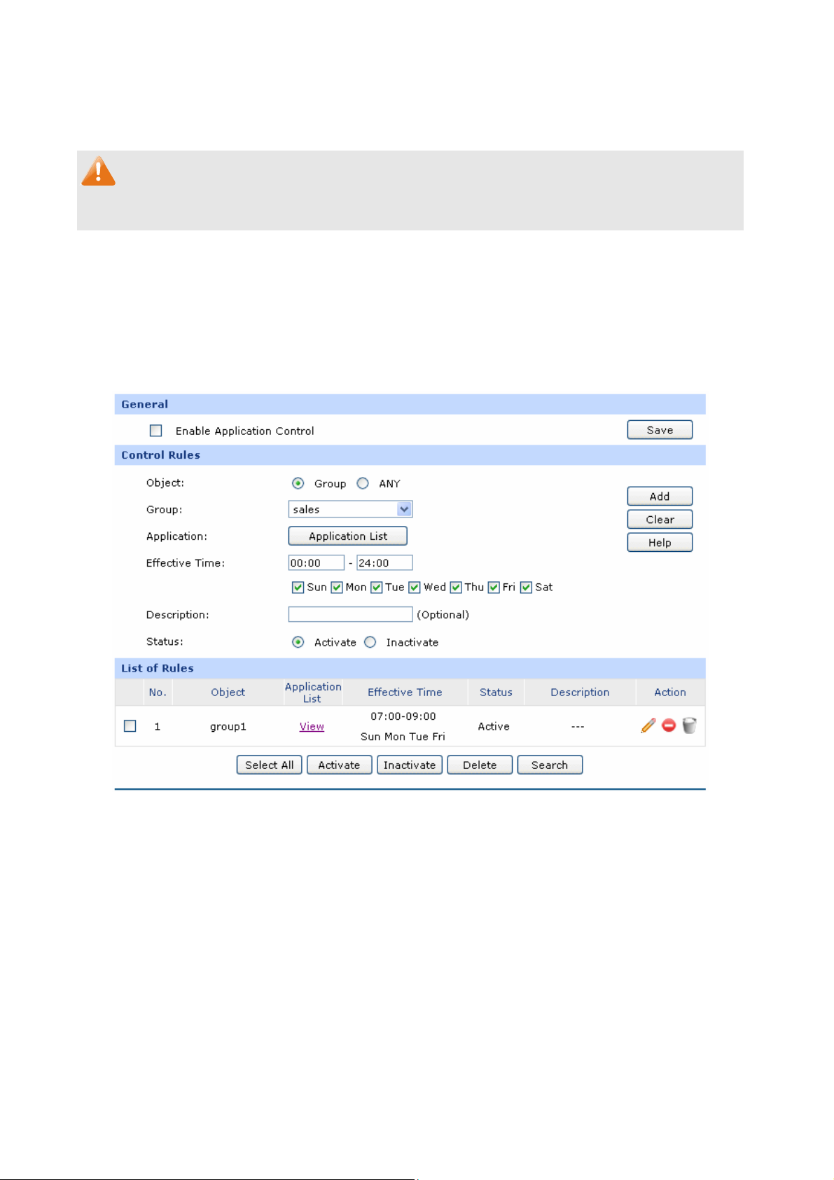
List of Service
ou can view the informati
Y
Note:
The service types predefined
on of the entries and edit them by the Action buttons.
by the system cannot be modified.
3.4.5 App Control
3.4.5 l Rules
.1 Contro
On this page, you can enable
Choose the menu Firewall→ llowing page.
the Application Rules function.
App Control→Control Rules to load the fo
Figure 3-55 Application Rules
The following items are displayed on this screen:
General
Check the box before Enable Application Control to make the Application Control function take
effect. The specified application used by the specified local users will be not allowed to access the
Internet if the Application Control entry is enabled.
-77-
Page 84
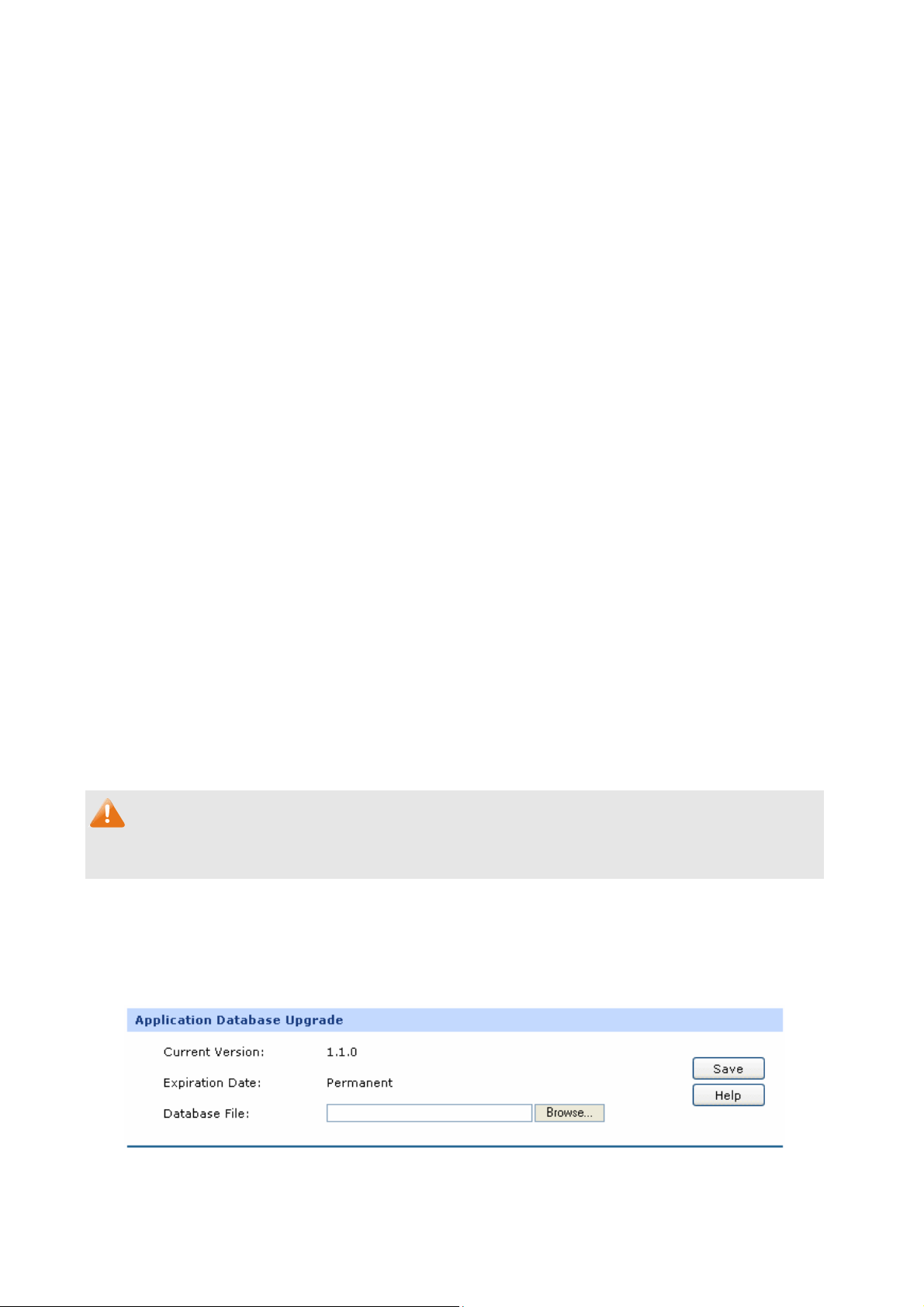
Control Rules
Object:
Group:
Application:
Effective Time:
Description:
Status:
pecify the object for the entry. Yo
S
predefined group, or select “ANY” to limit all the users.
If select “Group” as object, you can select the group in the drop-down list.
To establish new group, please refer to 3.2.1 Group.
Click the <Application List> button to select applications from the po
checkbox.
and Proxy. The default setting is to limit all the applications in the
application list except for Basic and Proxy.
Specify the tim
Give a description for the entry.
Activate or inactivate the entry.
The applications include IM, Web IM, SNS, P2P, Media, Basic
e for the entry to take effect.
u can select “Group” to limit the
pup
List of Rules
You can view the information of the entries and edit them by the Action buttons.
The first entry in Figure 3-55 indicates: The group1 is applied with Application
<View> to view the limited e effective time of this entry is
7:00-9:00 on Monday, Tuesday, Friday, Saturday and Sunday. This entry is enabled.
Note:
To set the group and group members, please refer to 3.2.1 Group.
applications in the popup checkbox. Th
Rules. You can click
3.4.5.2 Database
On this page, you can upgrade the application database.
Choose the menu Firewall→App Control→Database to load the following page.
Figure 3-56 Database
-78-
Page 85
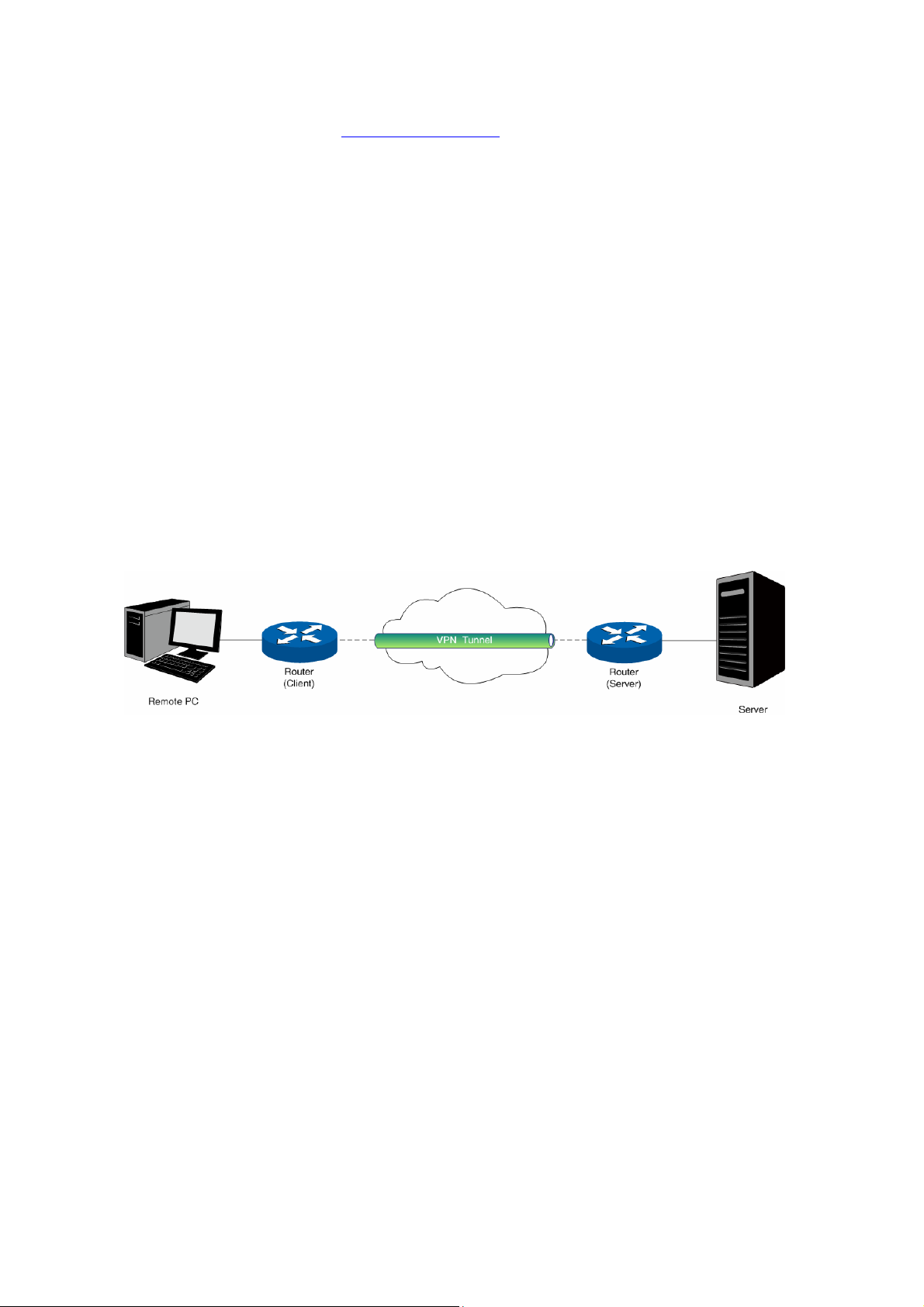
The database refers to all the applications in the application list on the Application Rules page, you can
download the latest database from http://www.tp-link.com
file, and then click the <Up
grade> button to upgrade the database.
, Click the <Browse> button and select the
3.5 VPN
VPN (Virtual Private Network) is a private network established via the p
Internet. However, the private network is a logical network without any physical network lines, so it is
called Virtual Private Network.
With the wide application of the Internet, more and more data are needed to be shared through the
Internet. Connecting the local network to the Internet directly, though can allow the data exchange, will
cause the private data to be exposed to all the users on the Internet. The VPN (Virtual Private Network)
technology is developed and used to establish the private network through the public network, which
can guarantee a secured data exchange.
VPN adopts the tunneling technology to establish a private connection between two endpoints. It is a
connection secured by encrypting the data and using point-to-point authentication. The following
diagram is a typical VPN topology.
ublic network, generally via the
Figure 3-57 VPN – Network Topology
As the packets are encapsulated and de-encapsulated in the router, the tunneling topology
implemented by encapsulating packets is transparent to users. The tunneling protocols supported by
TL-ER6120 contain Layer 3 IPsec and Layer 2 L2TP/PPTP.
3.5.1 IKE
In the IPsec V
de-encapsulate the p
negoti y for co
ate a security ke mmunication with IKE (Internet Key Exchange) protocols.
Actually IKE is a hybrid prot t
Security Association and Key Management Protocol), Oakley Key Determination Protocol, and
SKEME Security Key Exchange Protocol. ISAKMP provides a framework for Key Exchange and SA
(Security Association) negotiation. Oakley describes a series of key exchange modes. SKEME
describes another key exchange mode different from those described by Oakley.
PN, to ensure a secure communication, the two peers should encapsulate and
ackets using the information both known. Therefore the two peers need to
ocol based on three underlying security protocols, ISAKMP (Interne
IKE consists of two phases. Phase 1 is used to negotiate the parameters, key exchange algorithm and
encryption to establish an ISAKMP SA for securely exchanging more information in Phase 2. During
-79-
Page 86
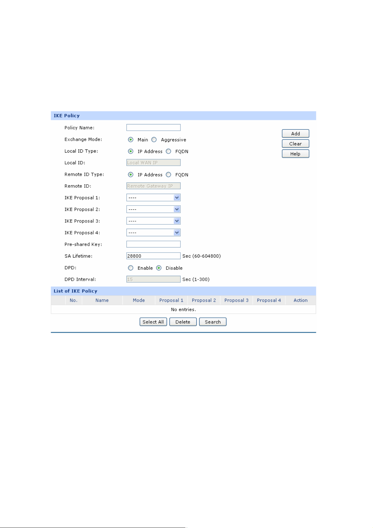
phase 2, the
security protocols in IPsec and he transmission data.
3.5.1.1 IKE Policy
On this page you can con
Choose the menu VPN
IKE peers use the ISAKMP SA established in Phase 1 to
create IPsec SA to secure t
figure the related parameters for IKE negotiation.
→IKE→IKE Policy to load the following page.
negotiate the parameters for
The fo re displa
llowing items a yed on this screen:
IKE Pol cy
i
Policy Name:
Specify a un
management purposes.
Figure 3-58 IKE Policy
ique name to the IKE policy for identification and
The IKE policy can be applied to IPsec policy.
-80-
Page 87

Exchange Mode:
Local ID Type:
Local ID:
Remote ID Type:
Select the IKE Exchange
Mode in phase 1, and ensure the remote VPN
peer uses the same mode.
Main: Main mode provides identity pro
information, which applie
s to the scenarios with higher requirement
tection and exchanges more
for identity protection.
Aggressive: Aggressive Mode establishes a faster connection but
with lower security, which applies to scenarios with lower
requirement for identity protection.
Select the local ID type for IKE negotiation. IP Address: uses an IP
address as the ID in IKE negotiation. FQDN: uses a name as the ID.
The local WAN IP will be inputted automatically if IP Address type is
selected. If Name type is selected, enter a name for the local device as
the ID i
n IKE negotiation
Select the remote ID type for IKE negotiation. IP Address: uses an IP
add
ress as the ID in IKE negotiation. FQDN: uses a name as the ID.
Remote ID:
IKE Proposal:
Pre-shared Ke
SA Lifetime
:
DPD:
DPD Interva
l:
y:
The remote gateway IP will be inputted automatically if IP Address type
is selected. If Name type is selected, enter the name of the remote peer
as the ID in IKE negotiation.
Select the Proposal for IKE negotiation phase 1. Up to four proposals
can be selected.
Enter the Pre-shared Key for IKE authentication, and ensure both the
two peers use the same key. The key should consist of visible characters
without blank sp
ace.
Specify ISAKMP SA Lifetime in IKE negotiation.
Enable or disable DPD (
endpoint can send a DPD request to the peer to inspect whe
Dead Peer Detect) function. If enabled, the IKE
ther the IKE
peer is alive.
Enter the interval after which the DPD is triggered.
List of IKE Policy
In this table, you can view the information of IKE Policies and edit them by the action buttons.
-81-
Page 88
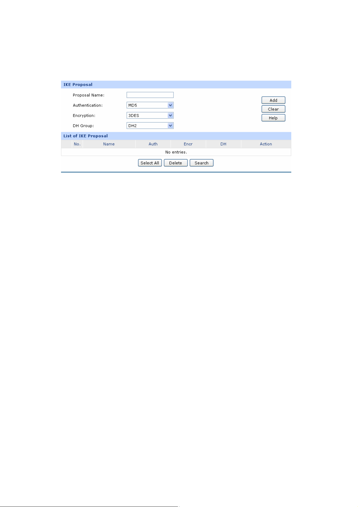
3.5.1.2 sal
On this page, you can define
IKE Propo
and edit the IKE Proposal.
Choose the menu VPN→IKE→IKE Proposal to load the following page.
Figure 3-59 IKE Proposal
The followin
g items are displayed on this screen:
IKE Proposal
Proposal Name:
Specify a unique name to the IKE proposal for identification and
management purposes. The IKE proposal can be applied to IPsec proposal.
Authentication:
Encryption:
Select the authentication algorithm for IKE negotiation. Options include:
MD5:
SHA1: SHA1 (Secure Hash Algorithm) takes a message less than
Specify the encryption algorithm for IKE negotiation. Options include:
DES: DES (Data Encryption Standard) encrypts a 64-bit block of plain
3DES: Triple DES, encrypts a plain text with 168-bit key.
MD5 (Message Digest Algorithm) t
akes a message of arbitrary
length and generates a 128-bit message digest.
2^64 (the 64
th power o
f 2) in bits and generates a 160-bit message
digest.
text with a 56-bit key.
AES128: Uses the AES algorithm and 128-bit key for encryption.
AES192: Uses the AES algorithm and 192-bit key for encryption.
AES256: Uses the AES algorithm and 256-bit key for encryption.
-82-
Page 89

DH Group:
Select the DH (Diffie-Hellman) group to be used in key negotiation phase
1. The DH Group sets the strength of the algorithm in bits. Options include
DH1, DH2 and DH5.
DH1: 768 bits
DH2: 1024 bits
DH3: 1536 bits
List of IKE Proposal
In this table, you can view the information of IKE Proposals and edit them by the action buttons.
3.5.2 IPsec
IPsec (IP Security) is a set of services and protocols defined by IETF (Internet Engineering Task Force)
to provide high security for IP packets and prevent attacks.
To ensure a secured communication, the two IPsec peers use IPsec protocol to negotiate the data
encryption algorithm and the security protocols for checking the integrity of the transmission data, and
exchange the key to data de-encryption.
IPsec has two important security protocols, AH (Authentication Header) and ESP (Encap
Security Payload). AH is used to guara the packet has been tampered during
ntee the data integrity. If
sulating
transmission, the receiver will drop this packet when validating the data integrity. ESP is used to check
the data integrity and encrypt the packets. Even if
the encrypted packet is intercepted, the third party
still cannot get the actual information.
3.5.2.1 IPsec Policy
On this page, you can define and edit the IPsec policy.
Choose the
menu VPN→IPsec→
IPsec Policy to load the following page.
-83-
Page 90
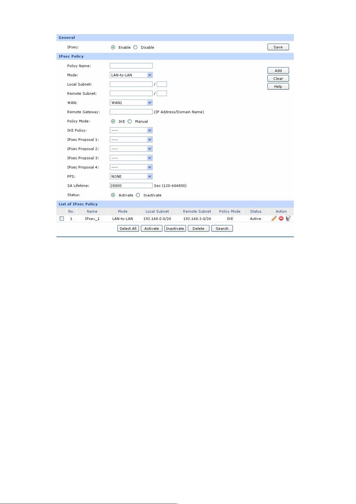
Figure 3-60 IPsec Policy
The followin
g items are displayed on this screen:
General
You can enable/dis ction for the router here.
able IPsec fun
IPsec Policy
Policy Name:
Specify a unique name to the IPsec policy. Up to 28 characters
can be entered.
Mode:
Select the network mode for IPsec policy. Options include:
LAN-to-LAN: Select this option when the client is a
network.
Local Subnet:
Client-to-LAN: Select this option when the client is a host.
S
pecify IP address range on your local LAN to identify which
PCs on your LAN are covered by this policy
. It's formed by IP
address and subnet mask.
-84-
Page 91

Remote
Subnet:
WAN :
Remote Gateway:
Policy Mode:
pecify IP address range on y
S
our remote network to identify
which PCs on the remote network are covered by this policy. It's
formed by IP address and subnet mask.
Specify the local WAN port for this Policy. The "Remote
Gateway" of the remote peer should be set to the IP address of
this WAN port.
Enter the Remote Gateway. It can be IP address or Domain
name.
Select the negotiation mode for the policy.
IKE: The parameters for the VPN tunnel are generated
automatically via IKE negotiations.
Manual: All settings (including the keys) for the VPN tunnel
are manually inputted and no key negotiation is needed.
IKE Mode
IKE Policy:
IPsec Proposal:
PFS:
It is available when IKE is selected as the negotiation mode.
pecify the IKE policy. If there is no policy selection, add new
S
policy on VPN→IKE→IKE Policy page.
Select IPsec Proposal on IKE mode. Up to four
IPsec Proposals
can be selected on IKE mode.
Select the PFS (Perfect Forward Security) for IKE mode to
enhance security. This setting should matc
h the remote peer.
With PFS feature, IKE negotiates to create a new key in
Phase2. As it is independent of the key created in Phase1, this
key can be secure even when the key in Phase1 is
de-encrypted. Without PFS, the key in Phase2 is created based
on the key in Phase1 and thus once the key i
n Phase1 is
de-encrypted, the key in Phase2 is easy to be de-encrypted, in
SA Lifetime:
this case, the communication secrecy is threatened.
Specify IPsec SA Lifetime for IKE mode.
-85-
Page 92

Status:
Manual Mode
ate or inactivate the entry.
Activ
IPsec Proposal:
Incoming
SPI:
AH Authentication Key-In:
ESP Authentication Key-In:
Select the IPsec Proposal. Only one proposal can be selected
on Manual mode. You need to first create the IPsec Proposal.
Specify the Incoming SPI (Security Parameter Index) manually
.
The Incoming SPI here must match the Outgoing SPI value at
the other end of the tunnel, and vice versa.
Specify the inbound AH Authentication Key manually if AH
protocol is used in the corresponding IPsec Proposal. The
inbound key here must match the outbound AH authentication
key at
the other end of the tunnel, and vice versa.
Specify the inbound ESP Authentication Key manually if ESP
protocol is used in the corresponding IPsec Proposal. The
inbound key here mus
t match the outbound ESP authentication
key at the other end of the tunnel, and vice versa.
ESP Encryption: Key-In:
Outgoing SPI:
AH Authentication Key-Out:
ESP Authentication Key-Out:
Specify the inbound ESP Encryption Key manually if ESP
protocol is used in the corresponding IPsec Proposal. The
inbound key here must match the outbound ESP encryption key
at the other end of the tunnel, and vice versa.
Specify the Outgoing SPI (Security Parameter Index) manually.
The Outgoing SPI here must match the Incoming SPI value at
the other end of the tunnel, and vice versa.
Specify the outbound AH Authentication Key manually if AH
protocol is used in the corresponding IPsec Proposal. The
outbound key here must match the inbound AH authentication
key at the other end of the tu
Specify the
outbound ESP Authentication Key manually if ESP
nnel, and vice versa.
protocol is used in the corresponding IPsec Proposal. The
outbound key here must match the inbound ESP authentication
key at the other end of the tunnel, and vice versa.
-86-
Page 93
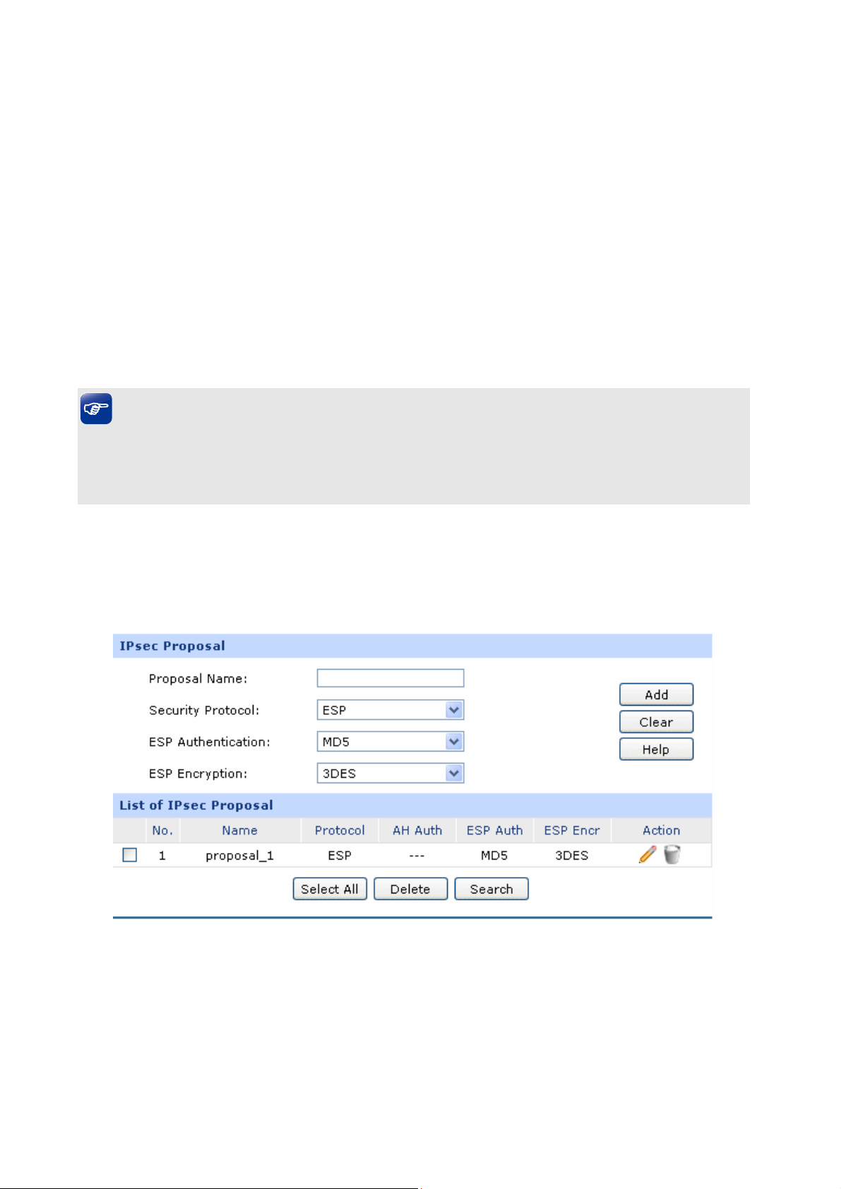
ESP Encryption
IP
List of IPsec Policy sec
In this table, yo
The first entry in Figure 3
the remote su
enabled.
Tips:
● 0.0.0.0.0/32 indicates all IP addresses.
● Refer to Appendix T
Key-Out:
u can view the information of IPsec policies and edit them by the action buttons.
-60 indicates: this is an IPsec tunnel, the local sub
bnet is 192.168.3.0/24 and this tunnel is using IKE automatic negotiation. It is
roubleshooting 5 for the configuration of subnet.
Specify the outbound ESP Encryption Key manually if ESP
protocol is used in the
outbound key here must match the inbound ESP encryption key
at the other end of the tunnel, and vice versa.
corresponding IPsec Proposal. The
net is 19
2.168.0.0/24,
3.5.2.2 IPsec Pro
On this page, you c
Choose the menu VPN
an define and edit the IPsec proposal.
posal
→IPsec→IPsec Proposal to load the following page.
Figure 3-61 IPsec Proposal
The following items are displayed on this screen:
-87-
Page 94

IPsec Proposal
Proposal Name:
Security Protocol:
AH Authentication:
Specify a unique name
management purposes. The IPs
to the IPsec Proposal for identification and
ec proposal can be applied to IPsec
policy.
Select the security protocol to be used. Options include:
AH: AH (A
authentication, dat
ESP: ESP (Encapsula
uthentication Header) provides data origin
a integrity and anti-replay services.
ting Security Payload) provides data
encryption in addition to origin authentication, data integrity, and
anti-replay services.
Select the algorithm used to verify the integrity of the data for AH
authentication. Options include:
MD5: MD5 (Message Digest Algorithm) takes a message of
arbitrar
y length and generates a 128-bit m s
es age digest.
ESP Authentication:
SHA: SHA (Secure Hash Algorithm) takes a
message less than the
64th power of 2 in bits and generates a 160-bit message digest.
Select the algorithm used to verify the integrity of the data for ESP
authentication. Options include:
MD5: MD5 (Message Digest Algorithm) takes a message of
arbitrary length and generates a 128-bit message digest.
SHA: S rithm) takes a message less than the
64th pow
HA (Secure Hash Algo
er of 2 in bits and generates a 160-bit message digest.
-88-
Page 95
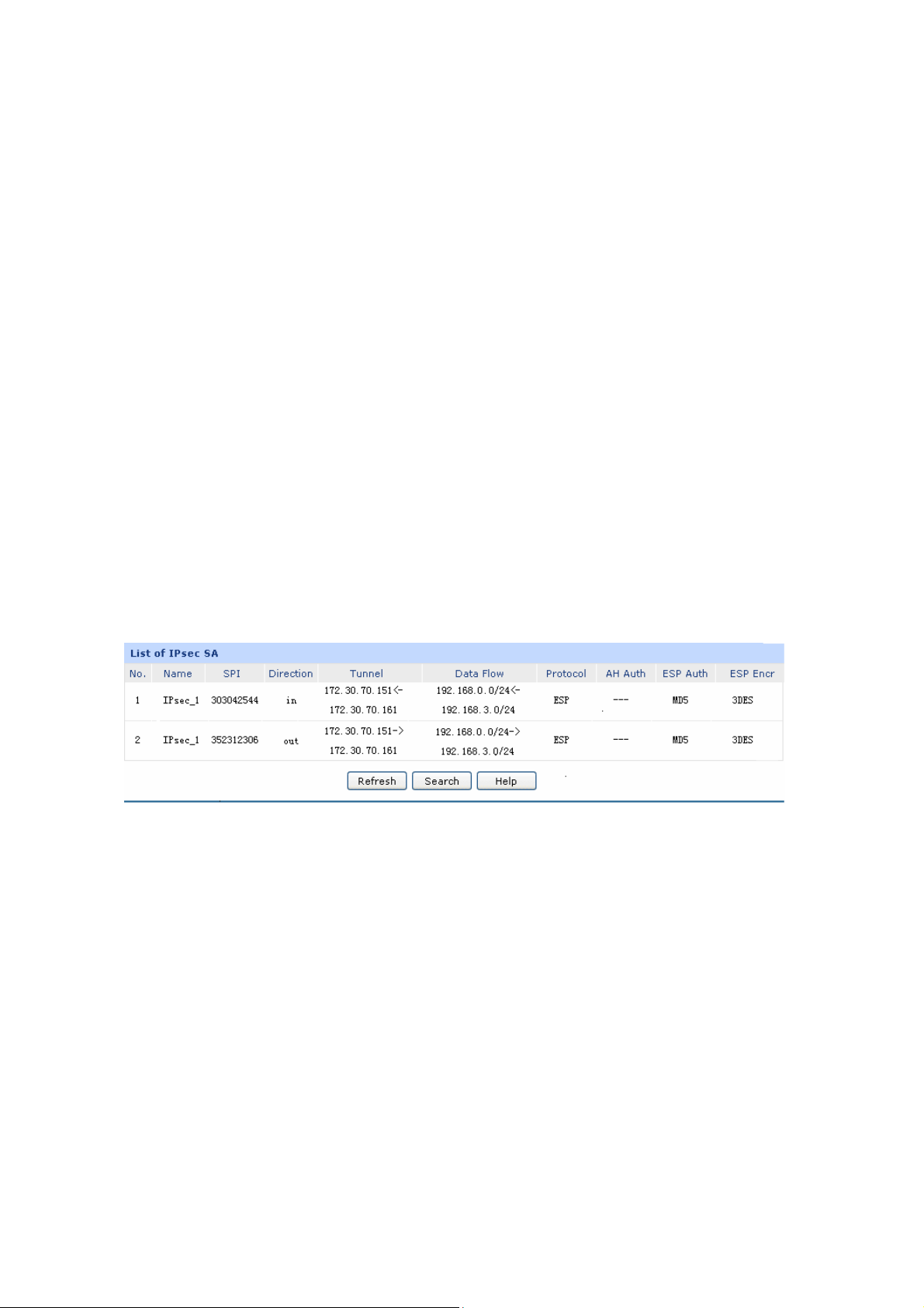
ESP Encryption:
List of IPsec Proposal
In this table, you can view the information of IPsec Proposals and edit them by the action buttons.
3. IPs
5.2.3 ec SA
Select the algorithm used to encrypt the data for ESP encryption.
Options include:
NONE: Performs no encryption.
DES: DES (Data Encryption Standard) encrypts a 64-bit block of plain
text with a 56-bit key. The key should be 8 characters.
3DES: Triple DES, encrypts a plain text with 168-bit key. The key should
be 24 charac
AES128: Uses the AES algorithm and 128-bit key for encryption. The
key should be 16 characters.
ters.
This page displays the information of the IPsec SA (Security Association).
Choose the men A to g
Figure 3-62 displays the connection status of
As shown in the figure, the router is using WAN2 for tunnel connection, and the IP address of WAN2
and the default gateway of remote peer are 172.30.70.151 and 172.30.70.161 respectively. Security
protocol and other parameters for IPsec tunnel and the remote router should be configured the same.
As Security Association is unidirectional, an ingoing SA and an outgoing SA are created to protect data
u VPN→IPsec→IPsec S load the followin page.
Figure 3-62 IPsec SA
the NO.1 entry in the List of IPsec policy in Figure 3-60.
flows for each tunnel after IPsec tunnel is successfully established. The ingoing SPI value and
outgoing SPI value are different. However, the Incoming SPI value must match the Outgoing SPI value
at the other end of the tunnel, and vice versa. The connection status on the remote endpoint of this
tunnel is as the following figure shows. The SPI value is obtained via auto-negotiation.
-89-
Page 96

3.5.3 L2TP/PPTP
Layer 2 VPN tunneling protocol consists of L2TP (Layer 2 Tunneling Protocol) and PPTP (Point to
Point Tunneling Protocol).
Both L2TP and PPTP encapsulate packet and add extra header to the packet by using PPP (Point to
Point Protocol). Table depicts the difference between L2TP and PPTP.
Protocol Media Tunnel Length of Header Authentication
PPTP IP network Single tunnel 6 bytes at least Not supported
IP network of UDP, frame
L2TP
relay virtual circuit, X.25
virtual circuit
Multiple tunnels 4 bytes at least Supported
3.5.3.1 L2TP/PPTP Tunnel
On this page,
Choose the
you can configure the L2TP/PPTP VPN.
menu VPN→L2TP/PPTP→L2TP/PPTP Tunnel to load the following page.
-90-
Page 97
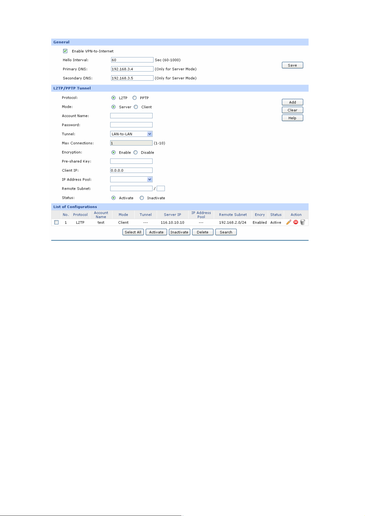
The following items are displaye
General
Enable VPN-to-Internet:
Hello Interval:
Primary/Secondary
DNS
el
L2TP/PPTP Tunn
Figure 3-63 L2TP/PPTP Tunnel
d on this screen:
Specify whether to enabl
e VPN-to-Internet function. If enabled, the
VPN client is permitted to access the LAN of the server and Internet.
Specify the interval to send hello packets.
Enter the Primary/Secondary DNS server address. The default IP is
"0.0.0.0", which means the LAN IP of the router is used as the DNS
server address.
Protocol:
Select the protocol for VPN tunnel. Options include L2TP and PPTP.
-91-
Page 98

Mode:
pecify the working mode for this router. Options include:
S
Client: In this mode, the device sends a request to the remote
Account Name:
word:
Pass
Tunnel:
L2TP/PPTP
Server: In this mode, the router responds the request from the
server initiatively for establishing a tunnel.
remote client for establishing a tunnel.
Enter the account name of L2TP/PPTP tunnel.
It should be configured
identically on server and client.
Enter the password of L2TP/PPTP tunnel. It should be configured
identically on server and client.
Select the network mode for the tunnel. Options include:
LAN-to-LAN: Select this option when the L2TP/PPTP client is a
LAN. The tunneling request is always initiated by a router.
Client-to-LAN: Select this option when the L2TP/PPTP client is a
single PC.
Max Connections:
WAN :
Server IP:
Encryption:
Pre-shard Key:
pecify the maximum connections that the tunnel can support. This
S
item is available for Cl
Specify the WAN port to transmit the packets. This
ient-to-LAN tunnel type on Server mode.
item is available
for Client mode.
Enter the IP address of L2TP/PPTP server. (It’s always the WAN IP
address of the remote peer of L2TP/PPTP tunnel.) This item is
available for Client mode.
Specify whether to enable the encryption for the tunnel. If enabled,
the L2TP tunnel will be encrypted by IPsec, and the PPTP tunnel will
be encrypted by MPPE.
Enter the Pre-shared Key for IKE authentication. This item is available
for L2TP tunnel.
-92-
Page 99
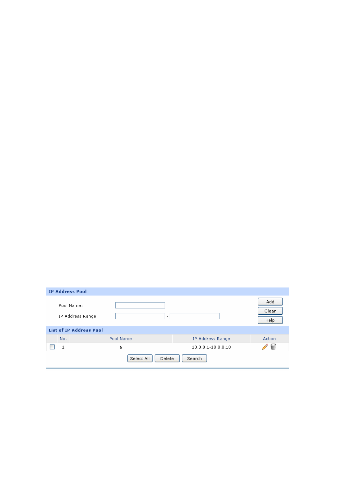
Client IP:
IP Address Pool:
Remote Subnet:
Status
List of Configurations
In this table, you can view your configurations of the tunnels and edit them by the action buttons.
Enter the IP
L2TP/PPTP server. The default IP "0.0.0.0" means any IP address is
acceptable.
Select the IP Pool Name to specify the address range for the server's
IP assignment. This item is available for Server mode.
Enter the IP address range of your remote network. (It's always the IP
address range of LAN on the remote peer of VPN tunnel.) It’s the
combination of IP address and subnet mask.
Activate or in
address of the client which is allowed to connect to this
activate the entry.
The No.1 entry in Figure 3-63 indicates: this tunnel is encapsulated by using L2TP
is test, the password can be configured, and the router is configured in Client mode. The remote
server is 116.10.10.10 and the remote subnet is 192.168.2.0/24. This entry is enabled.
3.5.3.2 IP Address Poo
On this page, you can configure the IP Address Pool.
Choose the menu VPN→L2TP/PPTP→IP Address Pool to load the following page.
l
. Its user name
Figure 3-64 IP Address Pool
his screen: The following items are displayed on t
-93-
Page 100
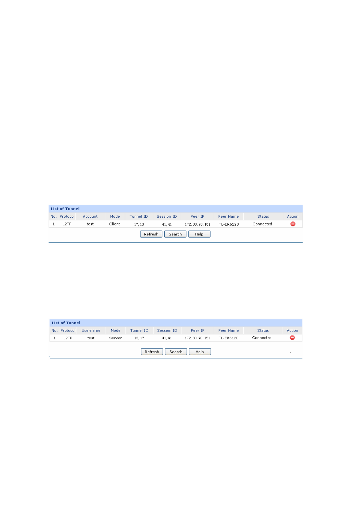
IP
List of IP Pool
Address Pool
S
Pool Name:
IP Address Range:
In this table, you can view the information of IP Pools and edit them by the action buttons.
pecify a unique name to the IP Address Pool for identification and
management purposes.
Specify the start and the end IP address for IP Pool. Th
should not exceed the end address and the IP ranges must not overlap.
e start IP address
3.5.3.3 List of L2TP/PPTP Tunnel
This page displays the information and status of the tunnels.
Choose the menu VPN→L2TP/PPTP→List of L2TP/PPTP Tunnel to load the following page.
Figure 3-65 List of L2TP/PPTP Tunnel
Figure 3-65 di
tunnel has been successfully established. Each tunnel has a Tunnel ID and a Session ID. The ID value
in cl to that in erver is shown
ient corresponds server. The connection information of this tunnel in the s
as the figure below.
ID values of different tunnels are
reconnected.
splays the connection status of
tablished, a tunEvery time a tunnel connection is es nel ID and a session ID are created. In a router, the
different. A tunnel can create different ID values when it is
the NO.1 entry in the list of tunnel in Figure 3-64. This
3.6 Services
3.6.1
The router can be configured as a PPPoE server to specify account and IP address to users in LAN and
thus you can control the dial-up of users for a high efficiency in network management.
PPPoE Server
-94-
 Loading...