

Page 1

Installation Guide
2x2 MIMO Dish Antenna
TL-ANT2424MD & TL-ANT5830MD
Page 2

Contents
Introduction
Specifications
Safety Notice
Package Contents
Installation Requirements
Hardware Overview
Hardware Installation
1
1
2
2
3
3
4
Page 3

Introduction
The TL-ANT2424MD, 2.4GHz 24dBi 2x2 MIMO Dish Antenna, can
be used together with the outdoor wireless Base Station WBS210
to achieve a stable long-distance point-to-point signal
transmission.
The TL-ANT5830MD, 5GHz 30dBi 2x2 MIMO Dish Antenna, can
be used together with the outdoor wireless Base Station WBS510
to achieve a stable long-distance point-to-point signal
transmission.
Specications
Electrical Specifications TL-ANT2424MD TL-ANT5830MD
Frequency Range
Gain
VSWR
HPOL Beamwidth (3 dB)
VPOL Beamwidth (3 dB)
Elevation Beamwidth (3 dB)
F/B Ratio
Polarization
Impedance
Connector
2.3 - 2.7 GHz
24 dBi
1.8 Max
6°
6°
6°
32 dB Min
Horizontal & Vertical
50 Ω
RP-SMA Female
5.0 - 6.0 GHz
30 dBi
1.8 Max
6°
6°
6°
34 dB Min
Horizontal & Vertical
50 Ω
RP-SMA Female
Mechanical Specifications
Antenna Dimension
Weight
Rated Wind Velocity
Mounting
Φ 600 mm
6.0 Kg
241 Km/h
Pole Mount
1
Page 4
Safety Notice
Heed all warnings:
Mount the antenna at a safe location, far away from power lines, lamp
posts, and other electrical cables.
Do not mount the antenna in the rain or thunderstorm.
Avoid using this product during an electrical storm. There may be a
remote risk of electric shock from lightning.
For your own safety, please seek a qualified service technician for
assistance.
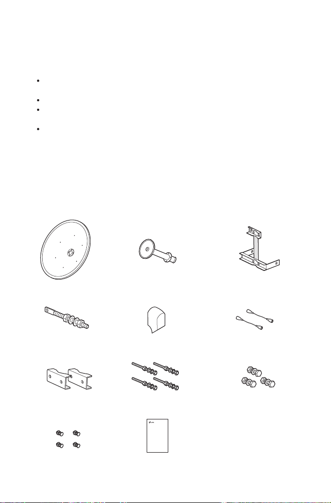
Package Contents
Below displays the package contents of the TL-ANT5830MD. The TL-ANT2424MD
comes with the Antenna Feed and RF Cables pre-attached.
Antenna FeedDish Reector Antenna Mount Bracket
Elevation Rod Protective Shroud
Pole-mount Clamps
(Qty. 2)
M4 Bolts
(Qty. 4)
M10x150 Carriage Bolt Assemblies
(Qty. 4)
Installation Guide
2x2 MIMO Dish Antenna
TL-ANT2424MD & TL-ANT5830MD
Installation Guide
RF Cables
(Qty. 2)
M10x35 Carriage Bolt Assemblies
2
(Qty. 3)
Page 5

Installation Requirements
Outdoor Wireless Base Station (sold separately)
Phillips Screwdriver
Wrenches
Hardware Overview
Dish Reflector
Pole-mount Clamp
Protective Shroud
Antenna-mount Bracket
Pole-mount Clamp
3
Page 6

Hardware Installation
1. Secure the Antenna Feed to the Dish Reflector using the four
M4 Bolts and a Phillips screwdriver.
Note: Do not handle the Dish Reflector by the Antenna Feed once the feed
is installed.
2. Connect the RF Cables to the RF Connectors on the Antenna
Feed.
Note: TL-ANT2424MD doesn't require this step, please go directly to step 3.
4
Page 7

3. Attach the Base Station to the Dish Reflector as follows:
a. Align the mounting tabs on the back of the Base Station with
the four mounting slots on the Base Station mounting bracket.
b. Slide the Base Station down until it locks into place.
4. Connect the other ends of the RF Cables to the Base Station.
5
Page 8

5. Attach the Elevation Rod to the Antenna-mount Bracket using
the flat washers and nuts as shown below.
6. Attach the M10x150 Carriage Bolt Assemblies to the
Antenna-mount Bracket:
a. Remove the flat washer, spring washer, and nut that are
threaded on each M10x150 Carriage Bolt Assembly. Set them
aside as they will be used to secure the antenna to a pole in
step 8.
b. Insert the four M10x150 Carriage Bolts into the
Antenna-mount Bracket.
6
Page 9

7. Attach the Dish Reflector to the Antenna-mount Bracket:
a. Secure one M10x35 Carriage Bolt Assembly to attach the
Dish Reflector to the Elevation Rod.
b. Secure two M10x35 Carriage Bolt Assemblies to attach the
Dish Reflector to the lower section of the Antenna-mount
bracket.
7
Page 10

8. Mount the antenna assembly to the pole using the two
Pole-mount Clamps and the four sets of flat washers, spring
washers and nuts of the M10x150 Carriage Bolt Assemblies.
Note:
1.Pole diameter ranges from 1.5 in to 4.0 in.
2.Do not over-tighten these bolts and nuts to allow angle adjustment later.
3.In step 8 to 9, use the Level Vital to ensure proper alignment.
Level Vial
8
Page 11

9. Adjust the antenna azimuth and elevation angles with the front
facing the intended signal receiving devices to achieve
maximum signal strength:
a. To adjust azimuth, loosen the four nuts on the Pole-mount
Clamps slightly to pivot the antenna, then tighten the nuts.
b. To adjust the elevation angle, tighten or loosen the Elevation
Nuts on the Elevation Rod to the desired tilt.
Elevation Nuts
10. Slide the Protective Shroud down over the Base Station until
it locks into place.
9
Page 12

For technical support and other information, please visit
http://www.tp-link.com/support, or simply scan the QR code.
© 2017 TP-Link
7106507040 REV2.0.2
 Loading...