

Page 1
TD-W8968
300Mbps Wireless N USB ADSL2+ Modem Router
Rev: 3.0.0
1910
010970
Page 2

COPYRI
Specification
TP-LINK TECHNOLOGIES CO., LTD. Other brands and product names are trademarks or
registered trademarks of their respective holders.
No part of the specifications may be reproduced in any form or by any means or used to make any
derivative such as translation, transformation, or adaptation without permission from TP-LINK
TECHNOLOGIES CO., LTD. Copyright © 2014 TP-LINK TECHNOLOGIES CO., LTD. All rights
reserved.
http://www.tp-link.com
GHT & TRADEMARKS
s are subject to change without notice.
is a registered trad
emark of
Page 3

FCC STATEMENT
This equipment has been tested and found to co
pursuant to part 15 of the FCC Rules. These limits are designed to provide reasonable protection
against harmful interference in a residential installation. This equipment generates, uses and can
radiate radio frequency energy and, if not installed and used in accordance with the instructions,
may cause harmful interference to radio communications. However, there is no guarantee that
interference will not occur in a particular installation. If this equipment does cause harmful
interference to radio or television reception, which can be determined by turning the equipment off
and on, the user is encouraged to try to correct the interference by one or more of the following
measures:
• Reorient or relocate the receiving antenna.
• Increase the separation between the equipment and receiver.
• Connect the equipment into an outlet on a circuit different from that to which the receiver
is connected.
• Consult the dealer or an experienced radio/ TV technician for help.
This device complies with part 15 of the FCC Rules. Operation is subject to the following two
conditions:
1) This device may not cause harmful interference.
2) This device must accept any interference received, including interference that may cause
undesired operation.
mply with the limits for a Class B digital device,
Any changes or modifications not expressly approved by the party responsible for compliance
could void the user’s authority to operate the equipment.
Note: The manufacturer is not responsible for any radio or TV interference caused by
unauthorized modifications to this equipment. Such modifications could void the user’s authority to
operate the equipment.
FCC RF Radiation Exposure Statement
This equipment complies with FCC RF radiation
environment. This device and its antenna must not be co-located or operating in conjunction with
any other antenna or transmitter.
“To comply with FCC RF exposure compliance requirements, this grant is applicable to only
Mobile Configurations. The antennas used for this transmitter must be installed to provide a
separation distance of at least 20 cm from all persons and must not be co-located or operating in
conjunction with any other antenna or transmitter.”
exposure limits set forth for an uncontrolled
Page 4

Customer Information
This equipment complies with Part 68 of the FCC rules and the requirements
adopted by the ACTA. On the BOTTOM OF DEVICE is a label that contains,
among other information, a product identifier in the format US:
TPLDL01BTDW8968V3. If requested, this number must be provided to the
telephone company.
Applicable connector jack Universal Service Order Codes (“USOC”) for the
Equipment is RJ11C .
A plug and jack used to connect this equipment to the premises wiring and
telephone network must comply with the applicable FCC Part 68 rules and
requirements adopted by the ACTA. A compliant telephone cord and modular
plug is provided with this product. It is designed to be connected to a compatible
modular jack that is also compliant. See installation instructions for details.
The REN is used to determine the number of devices that may be connected to a
telephone line. Excessive RENs on a telephone line may result in the devices not
ringing in response to an incoming call. In most but not all areas, the sum of
RENs should not exceed five (5.0). To be certain of the number of devices that
may be connected to a line, as determined by the total RENs, contact the local
telephone company. For products approved after July 23, 2001, the REN for this
product is part of the product identifier that has the format US:
TPLDL01BTDW8968V3. The digits represented by 01B are the REN without a
decimal point (e.g., 03 is a REN of 0.3).
If this 300Mbps Wireless N USB ADSL2+ Modem Router causes harm to the
telephone network, the telephone company will notify you in advance that
temporary discontinuance of service may be required. But if advance notice isn't
practical, the telephone company will notify the customer as soon as possible.
Also, you will be advised of your right to file a complaint with the FCC if you
believe it is necessary.
The telephone company may make changes in its facilities, equipment,
operations or procedures that could affect the operation of the equipment. If this
happens the telephone company will provide advance notice in order for you to
make necessary modifications to maintain uninterrupted service.
If trouble is experienced with this 300Mbps Wireless N USB ADSL2+ Modem
Router, for repair or warranty information, please contact975 Overland Ct, San
Dimas, CA 91773 at +1 626-333-0234. If the equipment is causing harm to the
telephone network, the telephone company may request that you disconnect the
equipment until the problem is resolved.
Page 5

Connection to party line service is subject to state tariffs. Contact the state public
utility commission, public service commission or corporation commission for
information.
If your home has specially wired alarm equipment connected to the telephone
line, ensure the installation of this equipment does not disable your alarm
equipment. If you have questions about what will disable alarm equipment,
consult your telephone company or a qualified installer.
WHEN PROGRAMMING EMERGENCY NUMBERS AND(OR) MAKING TEST
CALLS TO EMERGENCY NUMBERS:
1) Remain on the line and briefly explain to the dispatcher the reason for the call.
2) Perform such activities in the off-peak hours, such as early morning or late
evenings.
Page 6

English version
''NOTICE: This equipment meets the applicable Industry Canada Terminal
Equipment Technical Specifications. This is confirmed by the registration
number. The abbreviation, IC, before the registration number signifies that
registration was performed based on a Declaration of Conformity indicating
that Industry Canada technical specifications were met. It does not imply that
Industry Canada approved the equipment.”
''NOTICE: The Ringer Equivalence Number (REN) for this terminal equipment
is 01B. The REN assigned to each terminal equipment provides an indication
of the maximum number of terminals allowed to be connected to a telephone
interface. The termination on an interface may consist of any combination of
devices subject only to the requirement that the sum of the Ringer Equivalence
Numbers of all the devices does not exceed five.''
French version
« AVIS : Le présent matériel est conforme aux spécifications techniques
d’Industrie Canadaapplicables au matériel terminal. Cette conformité est
confirmée par le numérod'enregistrement. Le sigle IC, placé devant le numéro
d'enregistrement, signifie quel’enregistrement s’est effectué conformément à
une déclaration de conformité et indique queles spécifications techniques
d'Industrie Canada ont été respectées. Il n’implique pasqu’Industrie Canada a
approuvé le matériel. »
« AVIS : L'indice d'équivalence de la sonnerie (IES) du présent matériel est de
01B. L'IESassigné à chaque dispositif terminal indique le nombre maximal de
terminaux qui peuvent êtreraccordés à une interface téléphonique. La
terminaison d'une interface peut consister en unecombinaison quelconque de
dispositifs, à la seule condition que la somme d'indicesd'équivalence de la
sonnerie de tous les dispositifs n'excède pas 5. »
Page 7

CE Mark Warning
This is a
which case the user may be required to take adequate measures.
class B product. In a domestic environment, this product may cause radio interference, in
Canadian Compliance Statement
This device
to the following two conditions:
(1)This device may not cause interference, and
(2)This device must accept any interference, including interference that may cause undesired
operation of the device.
Cet appareil est conforme aux norms CNR exemptes de licence d’Industrie Canada. Le
fonctionnement est soumis aux deux conditions suivantes:
(1)cet appareil ne doit pas provoquer d’interférences et
(2)cet appareil doit accepter toute interférence, y compris celles susceptibles de provoquer un
fonctionnement non souhaité de l’appareil.
Industry Canada
Complies with the Canadi
complies with Industry Canada license-exempt RSS standard(s). Operation is subject
Statement
an ICES-003 Class B specifications.
Cet appareil numérique de la classe B est conforme à la norme NMB-003 du Canada.
This device complies with RSS 210 of Industry Canada. This Class B device meets all the
requirements of the Canadian interference-causing equipment regulations.
Cet appareil numérique de la Classe B respecte toutes les exigences du Règlement sur le
matériel brouilleur du Canada.
Radiation Exposure Statement:
This equipment complies with IC radiation exposure limits set forth for an
uncontrolled environment. This equipment should be installed and operated
with minimum distance 20cm between the radiator & your body.
Korea Warning Statemen
Déclaration d'exposition aux radiations:Cet équipement est conforme aux
당해 무선설
비는 운용중 전파혼신 가능성이 있음.
ts
limites d'exposition aux rayonnements IC établies pour un environnement non
NCC Notice& BSMI Notice
contrôlé. Cet équipement doit être installé et utilisé avec un minimum de 20
cm de distance entre la source de rayonnement et votre corps.
注意!
依據 低功率
第十二條 經型式認證合格之低功率射頻電機,非經許可,公司、商號或使用者均不得擅自變更頻率、
加大功率或變更原設計之特性或功能。
電波輻射性電機管理辦法
第十四條 低功率射頻電機之使用不得影響飛航安全及干擾合法通行;經發現有干擾現象時,應立即
停用,並改善至無干擾時方得繼續使用。前項合法通信,指依電信規定作業之無線電信。低功率射
頻電機需忍受合法通信或工業、科學以及醫療用電波輻射性電機設備之干擾。
安全諮詢及注意事項
●請使用原裝電源供應器或只能按照本產品注明的電源類型使用本產品。
●清潔本產品之前請先拔掉電源線。請勿使用液體、噴霧清潔劑或濕布進行清潔。
Page 8

●注意防潮,請勿將水或其他液體潑灑到本產品上。
●插槽與開口供通風使用,以確保本產品的操作可靠並防止過熱,請勿堵塞或覆蓋開口。
●請勿將本產品置放於靠近熱源的地方。除非有正常的通風,否則不可放在密閉位置中。
●請不要私自打開機殼,不要嘗試自行維修本產品,請由授權的專業人士進行此項工作。
Продукт сертифіковано згідно с правилами сис
вимогамПродукт сертифіковано згідно с правилами системи УкрСЕПРО на відповідність
вимогам нормативних документів та вимогам, що передбачені чинними законодавчими
актами України.
теми УкрСЕПРО на відповідність
Safety Information
z
When product has power button, the power button is one of the way to shut off the product;
when there is no power button, the only way to completely shut off power is to disconnect the
product or the power adapter from the power source.
z Don’t disassemble the product, or make repairs yourself. You run the risk of electric shock
and voiding the limited warranty. If you need service, please contact us.
z Avoid water and wet locations.
This product can be used in the following countries:
AT BG BY CA CZ DE DK EE
ES FI FR GB GR HU IE IT
LT LV MT NL NO PL PT RO
RU SE SK TR UA
Page 9

TP-LINK TECHNOLOGIES
CLARATION OF CONFORMITY
DE
CO., L TD
For the following equi
Product Description: 300Mbps Wireless N USB ADSL2+ Modem Router
Model No.: TD-W8968
Trademark: TP-LINK
We declare under our own responsibility that the above products satisfy all the technical
regulations applicable to the product within the scope of Council Directives:
Directives 1999/5/EC, Directives 2004/108/EC, Directives 2006/
The above product is in conformity with the following standards or other normative documents
ETSI EN 300 328 V1.7.1: 2006
ETSI EN 301 489-1 V1.9.2:2011& ETSI EN 301 489-17 V2.2.1:2012
EN 55022:2010
EN 55024:2010
EN 61000-3-2:2006+A1:2009+A2:2009
EN 61000-3-3:2008
EN60950-1:2006+A11:2009+A1:2010+A12:2011
EN62311:2008
pment:
200
4/108/EC
The produc
t carries the CE Mark:
Person responsible for making this declaration:
Yang Hongliang
Product Manager of International Business
: 2014
TP-LINK TE
Date of issue
CHNOLOGIES CO., LTD
Building 24 (floors 1, 3, 4, 5), and 28 (floors 1-4) Central Science and Technology Park,
Shennan Rd, Nanshan, Shenzhen, China
Page 10

CONTENTS
Package Contents
Chapter 1. Product Overvie
1.1 Overview of
1.2 Main Features
1.3 Panel Layout
1.3.1 The Front Panel
1.3.2 The Back Panel
Chapter 2. Connecting the Mod
2.1 System Requirements
2.2 Installation Environmen
2.3 Connecting the
Chapter 3. Quick Inst
3.1 TCP/IP Con
....................................................................................................1
w...................................................................................2
the Modem Router .......................................................................................2
..................................................................................................................3
....................................................................................................................4
...................................................................................................................4
....................................................................................................................5
em Router.............................................................7
......................................................................................................7
t Requirements ...........................................................................7
Modem Router ........................................................................................8
allation Guide........................................................................9
figuration.......................................................................................................9
3.2 Quick Installation Guide .................................................................................................10
Chapter 4. Configuring the Mod
4.1 Login
4.2 Device Info
4.3 Quick Setup
4.4 Operation Mode
4.5 Advanced Setup
4.5.1 Layer2 Interfac
4.5.2 WAN Servic
4.5.3 3G Settings
4.5.4 MAC Clone
4.5.5 LAN
4.5.6 NAT
4.5.7 Sec
4.5.8 Parental Cont
4.5.9 Quality of Servic
..............................................................................................................................15
.....................................................................................................................15
....................................................................................................................16
.............................................................................................................16
.............................................................................................................17
e.................................................................................................................18
e...................................................................................................................... 19
........................................................................................................................28
.........................................................................................................................31
....................................................................................................................................32
....................................................................................................................................36
urity..............................................................................................................................41
rol.................................................................................................................44
e............................................................................................................... 46
em Router ..........................................................15
4.5.10 Bandwi
4.5.11 Routing
dth Control.............................................................................................................. 48
...............................................................................................................................51
Page 11

4.5.12 DNS
4.5.13 DSL
4.5.14 UPnP
4.5.15 Interface Grouping
4.5.16 IP Tunnel
4.5.17 IPSec
4.5.18 Multic
4.6 IPTV
4.7 Wireless
4.7.1 Basic .................................................................................................................................. 63
4.7.2 Sec
4.7.3 Wirel
4.7.4 MAC Filter
4.7.5 Wireless
4.7.6 Advanc
....................................................................................................................................52
....................................................................................................................................54
..................................................................................................................................55
.............................................................................................................55
............................................................................................................................57
..................................................................................................................................59
ast.............................................................................................................................61
...............................................................................................................................62
.........................................................................................................................63
urity..............................................................................................................................64
ess Schedule ............................................................................................................. 77
..........................................................................................................................78
Bridge.................................................................................................................. 79
ed........................................................................................................................... 80
4.7.7 Station info.........................................................................................................................82
4.8 Guest Network
4.8.1 Basic .................................................................................................................................. 82
4.8.2 Station lis
4.9 USB Setting
4.9.1 USB Mass
4.9.2 User Acc
4.9.3 Storage Shari
4.9.4 FTP Server
4.9.5 Media Server
4.9.6 Print Server
4.10 Diagnostics
4.11 Managemen
4.11.1 Settings
4.11.2 Sys
...............................................................................................................82
t........................................................................................................................... 83
s..................................................................................................................84
Storage ............................................................................................................ 84
ounts.................................................................................................................... 85
ng.................................................................................................................86
.........................................................................................................................88
......................................................................................................................89
........................................................................................................................90
.....................................................................................................................91
t..................................................................................................................91
..............................................................................................................................92
tem Log........................................................................................................................94
4.11.3 SNMP Agent
4.11.4 TR-069 client
4.11.5 Internet Time
4.11.6 Ac
4.11.7 Upgrade Firmware
4.11.8 Reboot
cess Control................................................................................................................... 98
......................................................................................................................95
......................................................................................................................96
......................................................................................................................98
...........................................................................................................100
..............................................................................................................................101
Page 12

4.12 Logout
Appendix A: Specifications
Appendix B: Troubleshooting
..........................................................................................................................101
.................................................................................103
.............................................................................104
Appendix C: Technical Support..........................................................................
107
Page 13

TD-W89
68 300Mbps Wireless N USB ADSL2+ Modem Router User Guide
Package Content
The followin
One TD-W8
¾
One pow
¾
Quick In
¾
¾
One RJ45 cable
Two RJ11 cables
¾
One ADSL splitter
¾
¾
One Resour
including:
•
•
Note:
)
Make sure that the package contains
missing, please contact your distributor.
g contents should be found in your package:
968 300Mbps Wireless N USB ADSL2+ Modem Router
er Adapter for TD-W8968 300Mbps Wireless N USB ADSL2+ Modem Router
stallation Guide
ce CD for TD-W8968 300Mbps Wireless N USB ADSL2+ Modem Router,
This User Guide
Other Helpfu
l Information
s
the above items. If any of the listed items are damaged or
1
Page 14

TD-W89
68 300Mbps Wireless N USB ADSL2+ Modem Router User Guide
Chapter 1. Product Overview
Thank you fo
r choosing the TD-W8968 300Mbps Wireless N USB ADSL2+ Modem Router.
1.1 Overview of the Modem Router
The TD-W8
Firewall, NAT-router and Wireless AP. Powered by 2x2 MIMO technology, the Wireless N router
delivers exceptional range and speed, which can fully meet the need of Small Office/Home Office
(SOHO) networks and the users demanding higher networking performance.
The TD-W8968 300Mbps Wireless N USB ADSL2+ Modem Router utilizes integrated ADSL2+
transceiver and high speed MIPS CPU. The modem router supports full-rate ADSL2+ connectivity
conforming to the ITU and ANSI specifications.
In addition to the basic DMT physical layer functions, the ADSL2+ PHY supports dual latency
ADSL2+ framing (fast and interleaved) and the I.432 ATM Physical Layer.
The modem router provides up to 300Mbps wireless connection with other 802.11n wireless clients.
The incredible speed makes it ideal for handling multiple data streams at the same time, which
ensu r e s y ou r n e tw o r k s t a b l e a nd smooth. T h e p e r f o r m a n ce of this 8 0 2. 1 1 n w i r e less modem route r w i l l
give you the unexpected networking experience at speed 650% faster than 802.11g. It is also
compatible with all IEEE 802.11g and IEEE 802.11b products.
968 300Mbps Wireless N USB ADSL2+ Modem Router integrates 4-port Switch,
With multiple protection measures, including SSID broadcast control and wireless LAN 64/128
WEP encryption, Wi-Fi protected Access (WPA2-PSK, WPA-PSK), as well as advanced Firewall
protections, the TD-W8968 300Mbps Wireless N USB ADSL2+ Modem Router provides complete
data privacy.
The modem router provides flexible access control, so that parents or network administrators can
establish restricted access policies for children or staff. It also supports Virtual Server and DMZ
host for Port Triggering, and then the network administrators can manage and monitor the network
in real time with the remote management function.
Since the modem router is compatible with virtually all the major operating systems, it is very easy
to manage. Quick Setup Wizard is supported and detailed instructions are provided step by step in
this user guide. Before installing the modem router, please look through this guide to know all the
modem router’s functions.
2
Page 15

TD-W89
68 300Mbps Wireless N USB ADSL2+ Modem Router User Guide
1.2 Main Features
One RJ11 LINE port, four 10/100M Auto-Negotiation RJ45 LAN ports, supporting Auto
¾
MDI/MDIX
¾ Complies with IEEE 802.11n to provide a wireless data rate of up to 300Mbps
¾ Quick response semi-conductive surge protect circuit, reliable surge-protect function
¾ AFE to support Annex A and L deployments
¾ Provides external splitter
¾ Multi-user sharing a high-speed Internet connection
¾ Connecting the internet on demand and disconnecting from the Internet when idle for PPPoE
¾ Provides WPA/WPA2, WPA-PSK/WPA2-PSK data security, TKIP/AES encryption security
¾ Provides 64/128-bit WEP encryption security and wireless LAN ACL (Access Control List)
¾ Adopts Advanced DMT modulation and demodulation technology
¾ Supports access control, parents and network administrators can establish restricted access
policies based on time of day for children or staff
¾ Supports Virtual Server, Port Triggering and DMZ host
¾ Supports UPnP, Dynamic DNS, Static Routing
¾ Supports bridge mode and router function
¾ Supports Web management
¾ Supports firmware upgrade
¾ Supports Flow Statistics
¾ Built-in firewall supporting IP address filtering, MAC address filtering and parental control
¾ Built-in DHCP server
¾ Supports USB Storage Sharing, Print Server, FTP Server, Media Server
¾ Supports IPv6
¾ Supports Guest Network
¾ Supports WPS
3
Page 16
TD-W89
68 300Mbps Wireless N USB ADSL2+ Modem Router User Guide
1.3 Panel La
yout
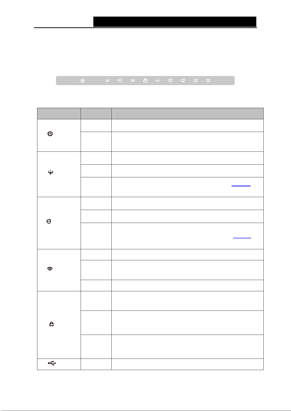
1.3.1 The Front Panel
The modem router’s LED
LED Explanation:
Name Status Indication
(Power
(ADSL)
)
s are located on the front panel (View from left to right).
On
Off
On
Flash
Off
Figure 1-
The modem router is pow
The modem router is off. Please ensure that the power adapter is
connected correctly.
ADSL line is
The ADSL negotiation is in progr
ADSL synchronization
troublesho
oting.
1
ered on.
synchronized and ready to use.
ess.
fails. Please refer to Note 1
for
(Internet)
(WLAN)
(WPS)
On
Flash
Off
On Wireless is enabled b
Flash
Off Wireless is disabled.
On
Slow Flash
Quick
Flash
The network
There is data being transmitted or received vi
There is no successful
is operating in Bridge mode. Please refer to Note 2
troubleshooting.
The modem
network.
A wireless device has be
WPS function.
WPS handshaking is in process and will continue for about
minutes. Please press the WPS button on other wireless devices
that you want to add to the network while the LED is flashing.
A wireless device has failed to be a
function. Please refer to 4.6.2.1 WPS Setup for more
information.
is available with a successful Internet connection.
a the Internet.
Internet connection or the modem router
fo
ut no data is being transmitted.
router is sending or receiving data over the wireless
en successfully added to the network by
2
dded to the network by WPS
r
(USB) On A storage de
vice or printer has connected to the USB port.
4
Page 17
TD-W89
68 300Mbps Wireless N USB ADSL2+ Modem Router User Guide
Flash
Off
On
(LAN1-
) Note:
If the ADSL LED is off, please check your Internet connection first. Refer to 2.3 Connecting
1.
the Modem Router for more information about how to make Internet con
you have already made a right connection, please contact your ISP to make sure if your
Internet service is available now.
2. If the Internet LED is off, please check your ADSL LED first. If your ADSL LED is also off,
please refer to Note 1. If your ADSL LED is GREEN ON, please check your Internet
configuration. You may need to check this part of information with your ISP and make sure
everything have been input correctly. Refer to 4.2 Device Info
4)
Flash
Off
The modem router is se
port.
No storage d
There is a device connected to this LAN port.
The modem router is se
port.
There is no device connected to this LAN port.
evice or printer is plugged into the USB port.
nding or receiving data over this USB
nding or receiving data over this LAN
nection correctly. If
for more information.
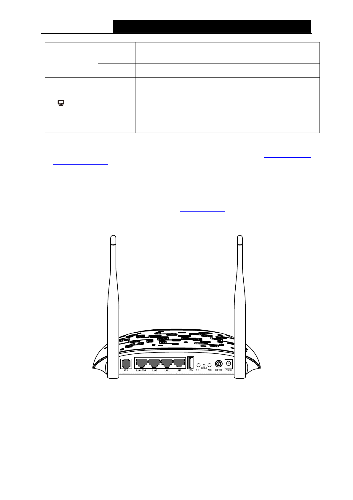
1.3.2 The Back Panel
Figure 1-
2
¾ ADSL: Connect to the Modem Port of Splitter or to the telephone line.
¾ LAN1, LAN2, LAN3, LAN4/WAN: Through these ports, you can connect the modem router to
your PC or the other Ethernet network devices. Enable EWAN function and you will be able to
connect to Cable/FTTH/VDSL/ADSL device.
¾ USB: The USB port connects to a USB storage device or a USB printer.
¾ WiFi: The switch for the WiFi function.
5
Page 18

TD-W89
68 300Mbps Wireless N USB ADSL2+ Modem Router User Guide
¾ RESET: There are two w
1) Use the Restore Default function on Management -> settings -> Restore Default page in
the modem router's Web-based Utility.
2) Use the Factory Default RESET button: With the modem router powered on, use a pin to press
and hold the RESET button for at least 5 seconds. And the modem router will reboot to its
factory default settings.
¾ WPS: The switch for the WPS function. For details, please refer to 4.6.2.1 WPS Setup
¾ ON/OFF: The switch
¾ POWER: The Power plug is where you will connect the power adapter.
¾ Wireless Antennas: To receive and transmit the wireless data.
ays to reset the modem router's factory defaults.
.
for the power.
6
Page 19
TD-W89
68 300Mbps Wireless N USB ADSL2+ Modem Router User Guide
Chapter 2. Connecting the Modem Router
2.1 Sy
¾
¾ PCs with a working Ethernet Adapter and an Ethernet cable with RJ45 connectors.
¾ TCP/IP protocol on each PC.
¾ Web browser, such as Microsoft Internet Explorer, Mozilla Firefox or Apple Safari.
2.2 Inst
¾
¾ Place the modem router in a location where it can be connected to the various devices as well
¾ Make sure the cables and power cord are safely placed out of the way so they do not create a
¾ The modem router can be placed on a shelf or desktop.
¾ Keep away from the strong electromagnetic radiation and the device of electromagnetic
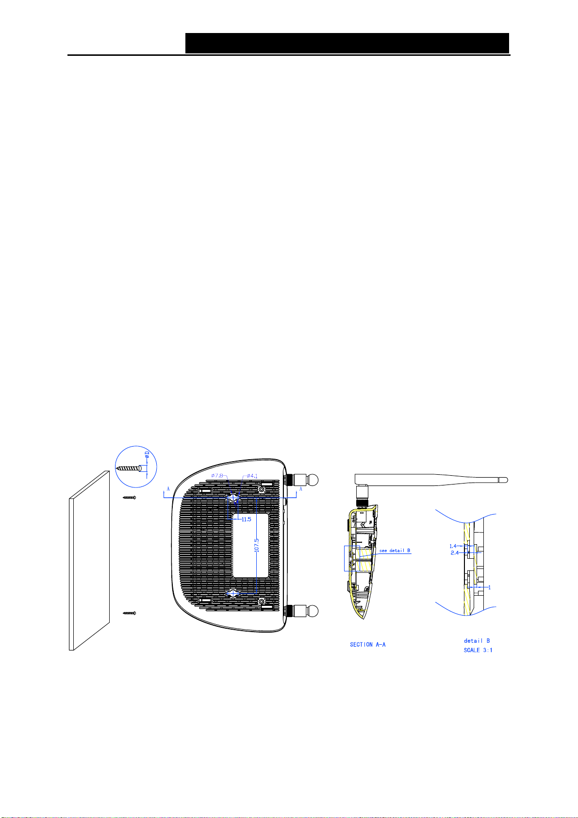
Generally, TD-W8968 is placed on a horizontal surface. The device also can be mounted on the
wall as shown in Figure 2-1.
stem Requirements
Broadband Internet Access Service (DSL/Cable/Ethernet).
allation Environment Requirements
The Product should not be located where it will be exposed to moisture or excessive heat.
as to a power source.
tripping hazard.
sensitive.
Figure 2-
Note:
)
The diamete
screw that project from the wall need around 4mm based, and the length of the screw need to be
at least 20mm to withstand the weight of the product.
r of the screw, 4.1mm<D<7.8mm, and the distance of two screws is 107.5mm. The
1 Wall-mount Install
7
Page 20
TD-W89
68 300Mbps Wireless N USB ADSL2+ Modem Router User Guide
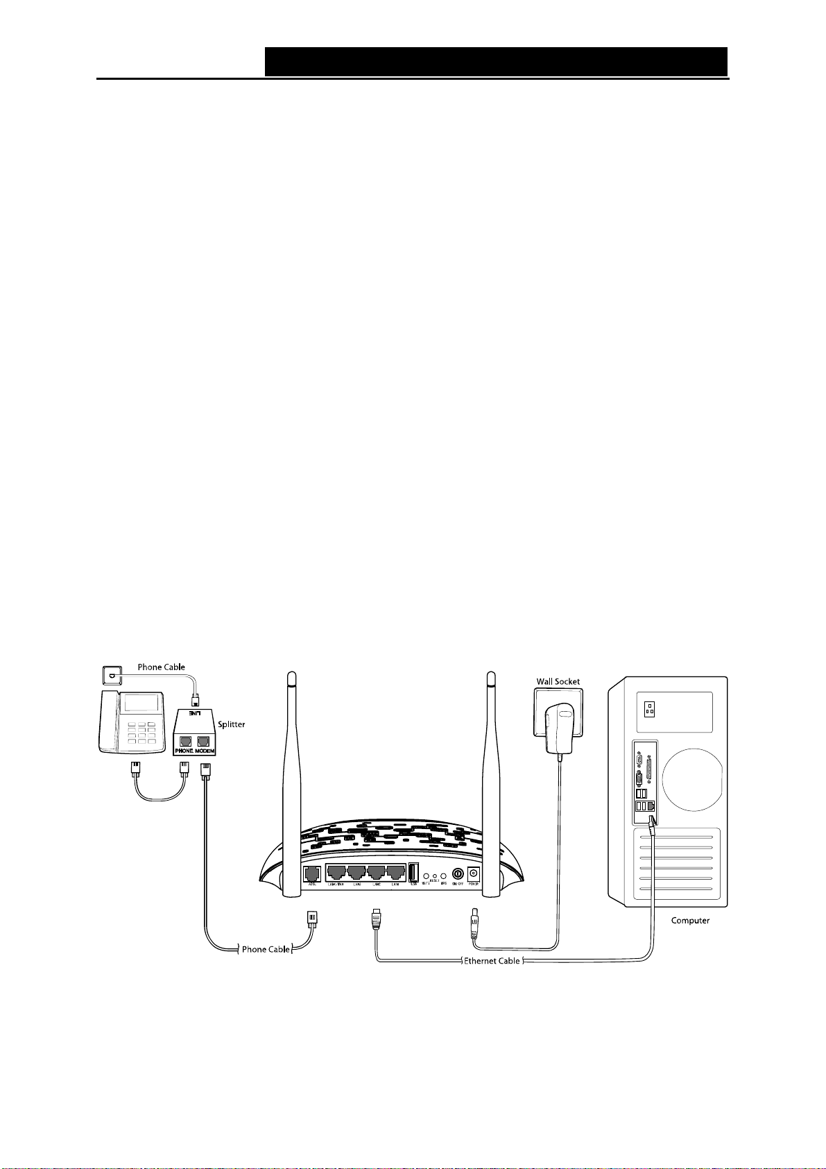
2.3 Connecting the Modem Router
Before installing the device, please
available. If there is any problem, please contact your ISP. Before cable connection, cut off the
power supply and keep your hands dry. You can follow the steps below to install it.
Step 1: Connect the ADSL Line.
Method one: Plug one end of the twisted-pair ADSL cable into the ADSL port on the rear
panelTD-W8968, and insert the other end into the wall socket.
Method two:You can use a separate splitter. External splitter can divide the data and
voice, and then you can access the Internet and make calls at the same time. The
external splitter has three ports:
• LINE: Connect to the wall jack
• PHONE: Connect to the phone sets
• MODEM: Connect to the ADSL port of TD-W8968
Plug one end of the twisted-pair ADSL cable into the ADSL port on the rear panel of
TD-W8968. Connect the other end to the MODEM port of the external splitter.
Step 2: Connect the Ethernet cable. Attach one end of a network cable to your computer’s
Ethernet port or a regular hub/switch port, and the other end to the LAN port on the
modem router TD-W8968.
make sure your broadband service provided by your ISP is
Step 3: Power on the computers and LAN devices.
Step 4: Attach the power adapter. Connect the power adapter to the power connector on the rear
of the device and plug in the adapter to a electrical outlet or power extension. The
electrical outlet shall be installed near the device and shall be easily accessible.
Figure 2-
8
2
Page 21
TD-W89
68 300Mbps Wireless N USB ADSL2+ Modem Router User Guide
Chapter 3. Quick Inst
This chapter will show you how to configure the basic functions of your TD-W89
Wireless N USB ADSL2+ Modem Router using Quick Setup Wizard within minutes.
3.1 TCP/IP
The default I
192.168.1.1. And the default Subnet Mask is 255.255.255.0. These values can be changed as you
desire. In this guide, we use all the default values for description.
Connect the local PC to the LAN/WAN port of the modem router. And then you can configure the
IP address for your PC in the following way.
¾
Obtain an IP
1) Set up the TCP/IP Protocol in "Obtain an IP address automatically" mode on your PC.
If you need instructions as to how to do this, please refer to T3 in Appendix B:
Troublesho
2)
Then the built-in DHCP server will assign IP address for the PC.
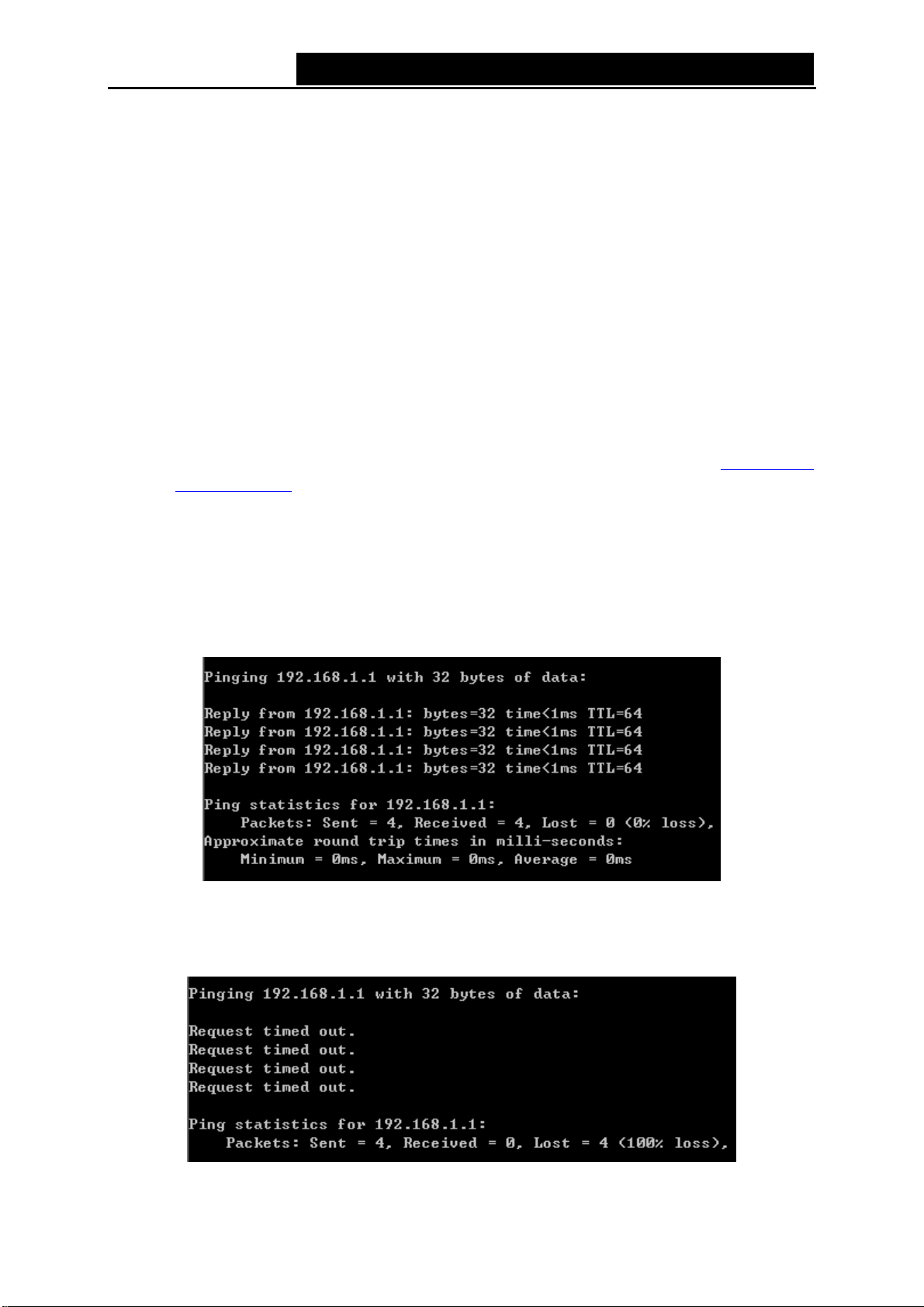
Now, you can run the Ping command in the command prompt to verify the network connection.
Please click the Start menu on your desktop, select run tab, type cmd or command in the field
and press Enter. Type ping 192.168.1.1 on the next screen, and then press Enter.
Configuration
P address of the TD-W8968 300Mbps Wireless N USB ADSL2+ Modem Router is
address automatically
.
oting
allation Guide
68 300Mbps
If the result displayed is similar to the screen below, the connection between your PC and the
modem router has been established.
Figure 3-
If the result displayed is similar to the screen shown below, it means that your PC has not
connected to the modem router.
1
Figure 3-
9
2
Page 22
TD-W89
68 300Mbps Wireless N USB ADSL2+ Modem Router User Guide
You can check
1) Is the connection between your PC and the modem router correct?
The LEDs of LAN port which you link to the device and the LEDs on your PC's adapter should
be lit.
2) Is the TCP/IP configuration for your PC correct?
If the modem router's IP address is 192.168.1.1, your PC's IP address must be within the
range of 192.168.1.2 ~ 192.168.1.254.
3.2 Quick Inst
With a Web-based utility, it is easy to
USB ADSL2+ Modem Router. The Web-based utility can be used on any Windows, Macintosh or
UNIX OS with a Web browser, such as Microsoft Internet Explorer, Mozilla Firefox or Apple Safari.
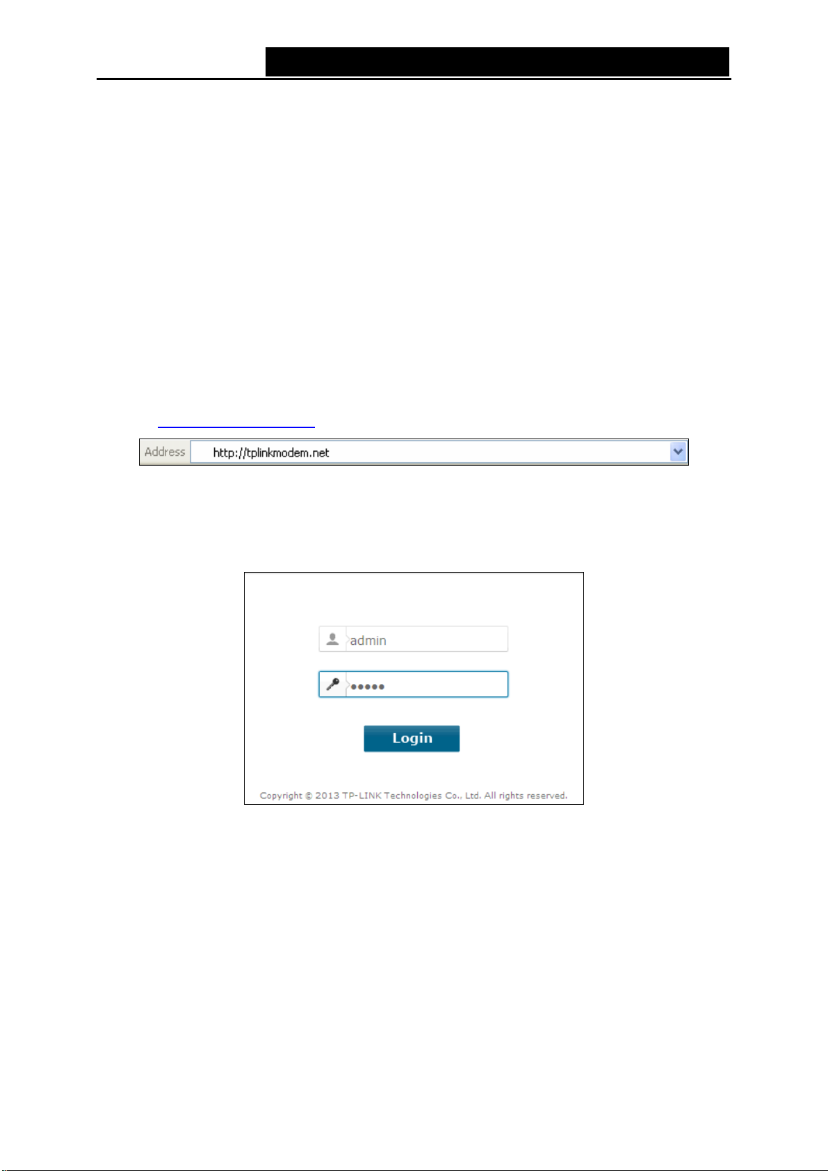
Step 1. To access the configuration utility, open a web-browser and type the default address
it following the steps below:
allation Guide
http://tplinkmodem.net
configure and manage the TD-W8968 300Mbps Wireless N
in the addres
s field of the browser.
Figure 3-
3
After a moment, a login window will appear, similar to the Figure 3-4. Enter admin for the
user name and password, both in lower case letters. Then click the Login button or press
the Enter key.
Figure 3-
Note:
)
Do not mix up the user name and password with your ADSL account user name and password
1)
which are needed for PPP connections.
4
2) If the above screen does not pop up, it means that your Web-browser has been set to a proxy.
Go to Tools menu→Internet Options→Connections→LAN Settings, in the screen that
appears, cancel the Using Proxy checkbox, and click OK to finish it.
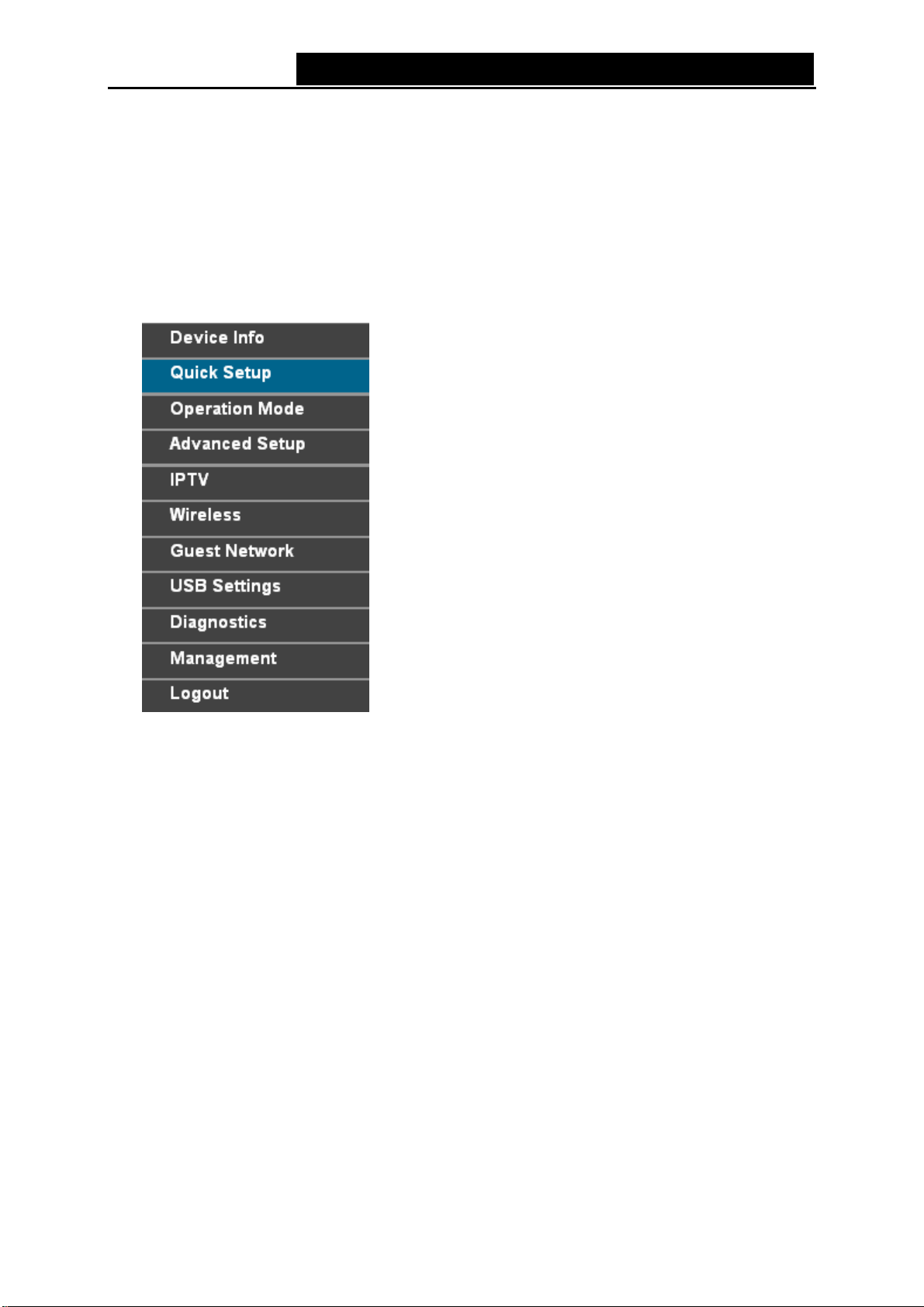
Step 2. After your successful login, you will see the Login screen as shown in Figure 3-5. Click
Quick Setup menu to access Quick Setup Wizard.
10
Page 23
TD-W89
Step 3. Click Next to continue.
68 300Mbps Wireless N USB ADSL2+ Modem Router User Guide
Figure 3-
5
Figure 3-
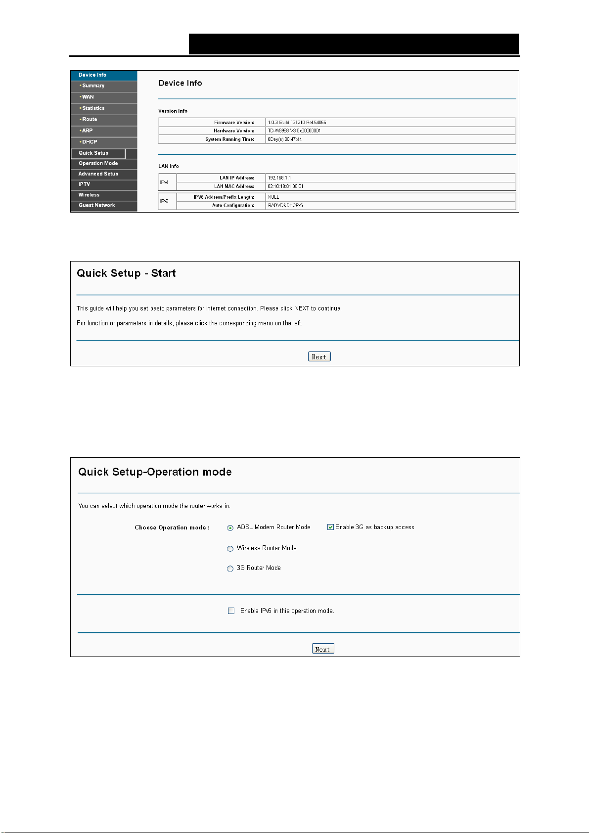
Step 4. Choose the Operation Mode for Internet access, and then click Next. For ADSL Modem
Router Mode and Wireless Router Mode, 3G Router Mode can be set as a backup
internet access method. If you do not want to configure 3G settings now, just untick the
option.
6
Figure 3-
¾ ADSL Modem Router Mode: In this mode, the device enables multi-users to share Internet
via ADSL using its ADSL port and share it wirelessly at 300Mbps wireless 802.11n speeds.
¾ Wireless Router Mode: In this mode, the device enables multi-users to share Internet via
Ethernet WAN (EWAN) using its interchangeable LAN/WAN port and share it wirelessly at
300Mbps wireless 802.11n speeds.
7
11
Page 24
TD-W89
68 300Mbps Wireless N USB ADSL2+ Modem Router User Guide
¾ 3G Router Mode: In this mode, the
connection via wired or wireless connection.
Note:
)
If you are unwilling to configure WAN Service now,
can configure WAN service referring to 4.4.1 Layer2 Interface
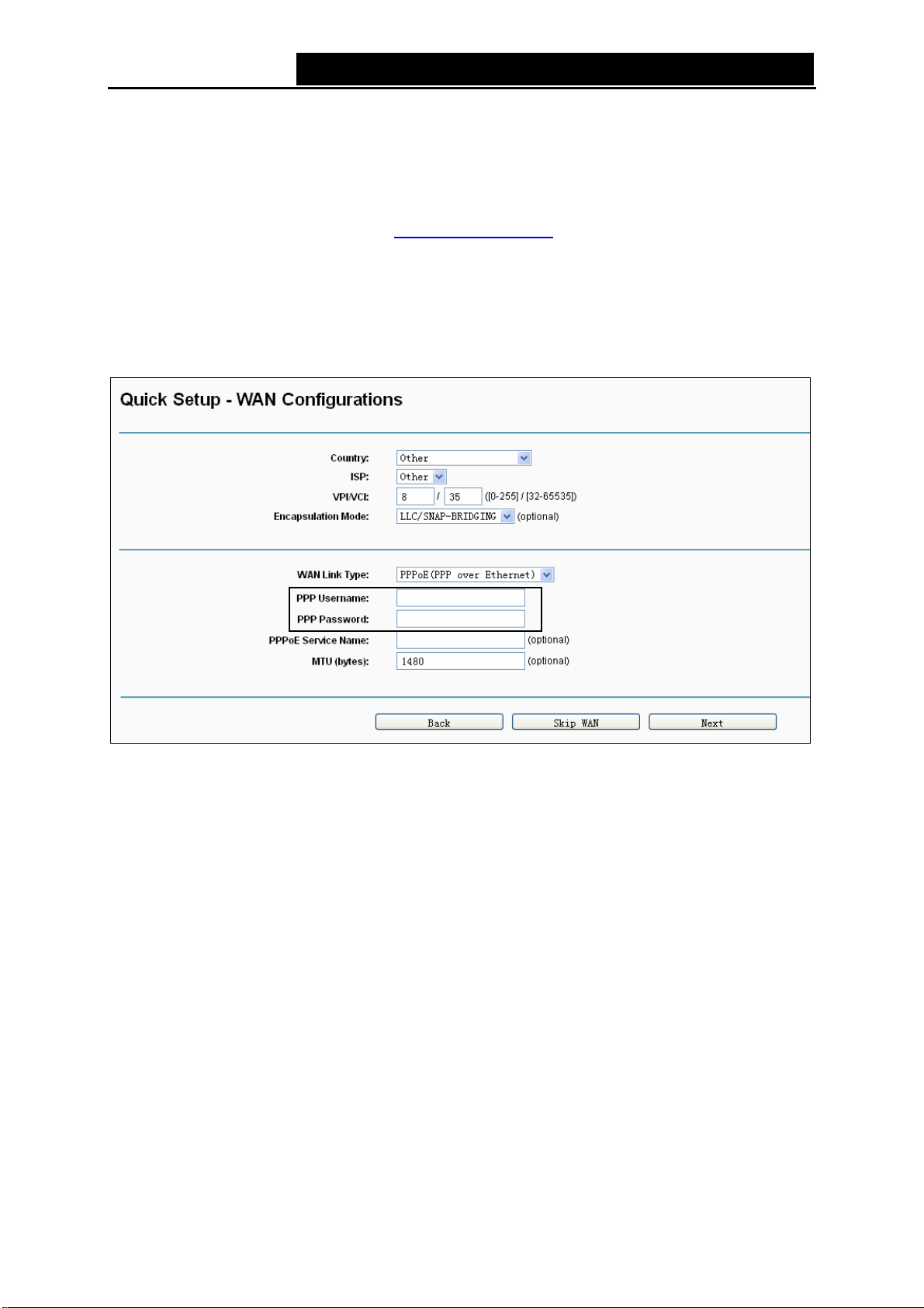
Step 5. Configur
Wireless Router Mode, 3G Router Mode
z If ADSL Modem Router Mode is chosen, please select your Country and ISP from the
drop-down list, and enter related parameters provided by your ISP. Then click Next. Here we
use PPPoE as an example.
e parameters for WAN connection. For ADSL Modem Router Mode and
device allows multi-users to share a 3G mobile broadband
you can click the Skip WAN button. Then you
.
Figure 3-8
Note:
)
If your count
values and select Encapsulation Mode provided by your ISP.
The country code selection is for non-US model only and is not available to all US model. Per FCC
regulation, all WiFi product marketed in US must fix to US operation channels only.
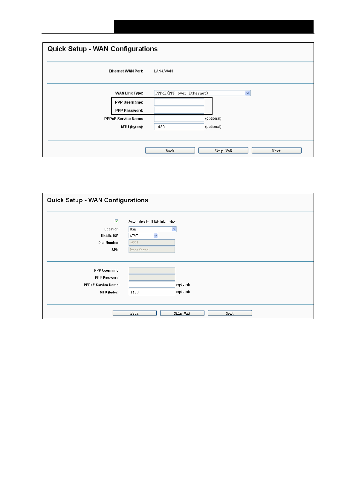
z If Wireless Router Mode is chosen, please select WAN Link Ty pe provided by your ISP and
ry or ISP is not listed, please select Other. Then you can manually enter the VPI/VCI
enter the related parameters, then click Next. Here we use PPPoE as an example.
12
Page 25
TD-W89
z If 3G Router Mode is chosen, you should first insert your 3G USB modem on the USB port of
the modem router. Then select your location and mobile ISP. Click Save to continue.
68 300Mbps Wireless N USB ADSL2+ Modem Router User Guide
Figure 3-
9
Figure 3-
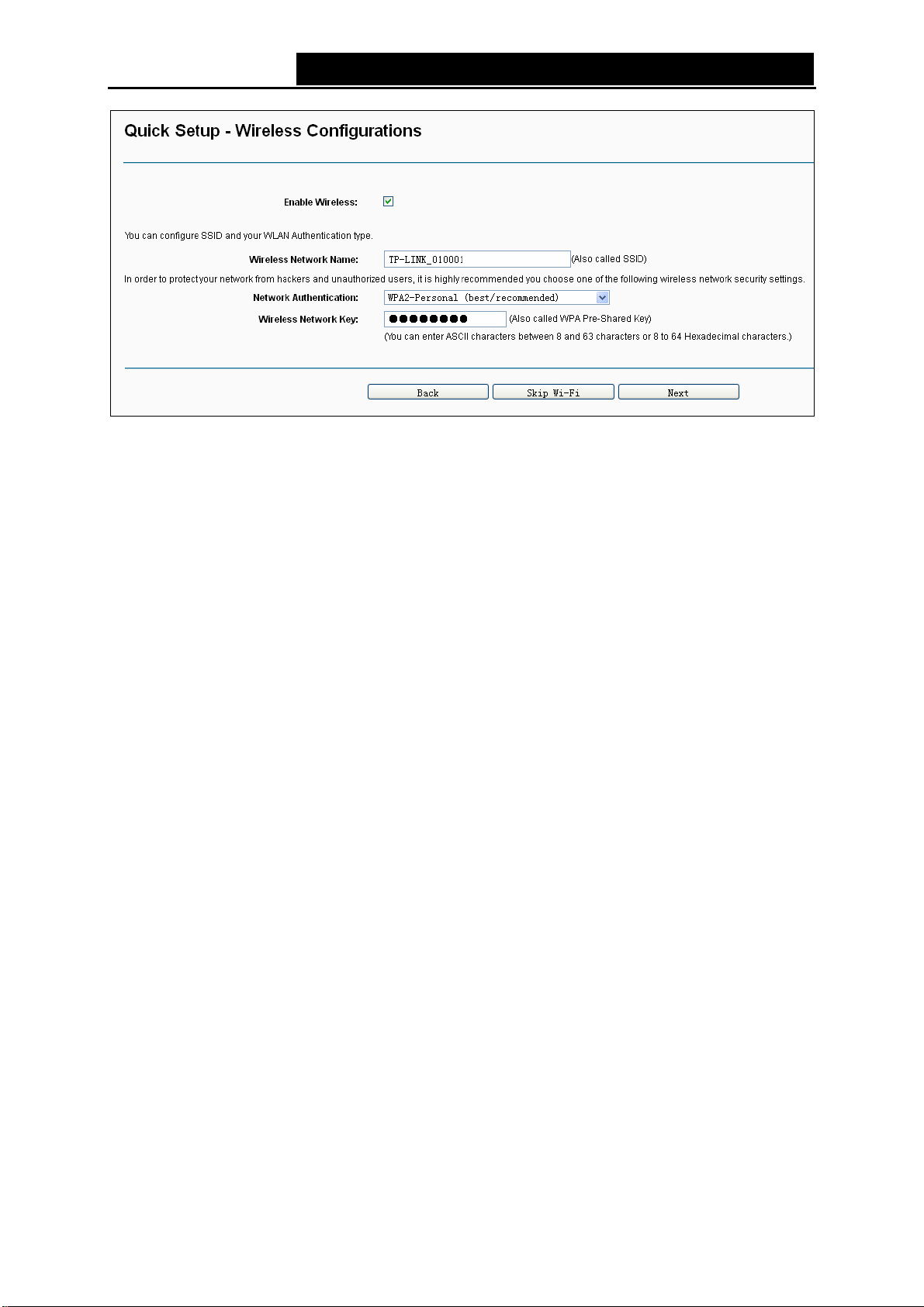
Step 6. The WLAN function is enabled by default. You can rename your wireless network name
and create your own password in this page. The default wireless name is
TP-LINK_XXXXXX, and the default wireless password, the same as the PIN code, is
printed on the bottom label. Click Next to continue.
10
13
Page 26
TD-W89
68 300Mbps Wireless N USB ADSL2+ Modem Router User Guide
Figure 3-
Step 7. You will see the Summary screen, click Confirm to make your settings take effect.
11
14
Page 27
TD-W89
68 300Mbps Wireless N USB ADSL2+ Modem Router User Guide
Chapter 4. Configuring the Modem Router
This chapter will show each Web page's key function and the configuration way.
4.1 Login
After your successful login, you will se
On the right, there are the corresponding explanations and instructions.
e the eight main menus on the left of the Web-based utility.
The detailed
explanations for each Web page’s key function are listed below.
4.2 Device Info
Choose “De
Statistics, Route, ARP and DHCP. This Device Info section mainly introduces the elementary
information about the modem router and its current settings in use. Click any of them, and you will
be able to view the corresponding information.
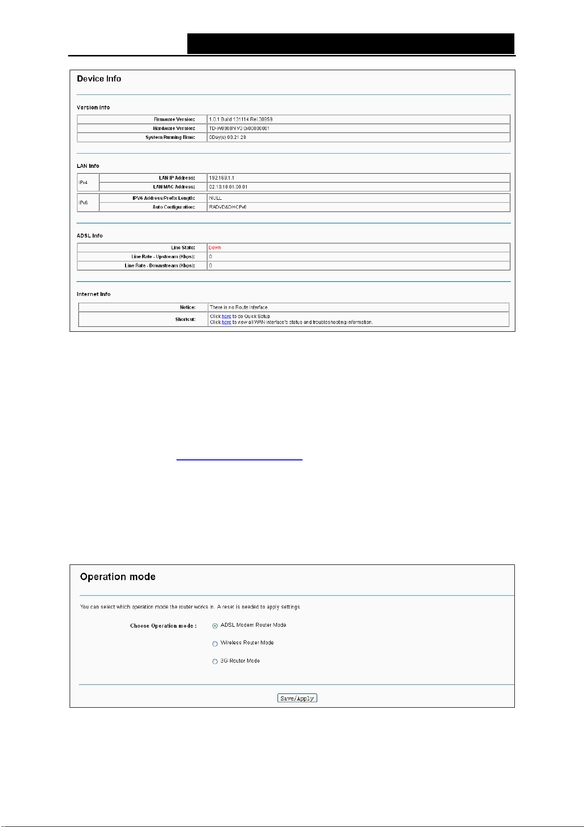
Choose “Device Info”Æ“Summary”, you will see the Summary screen (shown in Figure 4-1). The
first table indicates the information about the version including Software and Hardware. The
second table displays the current status of the Internet connection. This information will vary
depending on the settings of the modem router configured on the Advanced Setup screen.
vice Info” menu, there are six submenus under the main menu: Summary, WAN,
15
Page 28
TD-W89
68 300Mbps Wireless N USB ADSL2+ Modem Router User Guide
Figure 4-
1
Note:
)
Click the other submenu
corresponding information about WAN, Statistics, Route, ARP and DHCP.
s under the main menu Device Info, and you will be able to view the
4.3 Quick Setup
Please refer to Section 3.2 Quick
Installation Guide
.
4.4 Operation Mode
Choose “Op
router supports three operation mode types: ADSL Modem Router Mode, Wireless Router
Mode and 3G Router Mode. Select your desired mode and then click Save/Apply. Then the
modem router will reboot. Please wait.
eration Mode”, and you will see the screen as shown in Figure 4-2. The modem
Figure 4-
16
2
Page 29
TD-W89
68 300Mbps Wireless N USB ADSL2+ Modem Router User Guide
¾ ADSL Modem Router Mode: In this
via ADSL using its ADSL port and share it wirelessly at 300Mbps wireless 802.11n speeds.
¾ Wireless Router Mode: In this mode, the device enables multi-users to share Internet via
Ethernet WAN (EWAN) using its interchangeable LAN/WAN port and share it wirelessly at
300Mbps wireless 802.11n speeds.
¾ 3G Router Mode: In this mode, the device allows multi-users to share a 3G mobile broadband
connection via wired or wireless connection.
mode, the device enables multi-users to share Internet
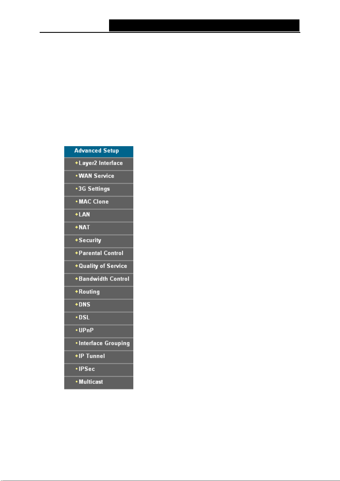
4.5 Advanced Setup
In ADSL Mo
main menu. Click any one of them, and you will be able to configure the corresponding function.
dem Router Mode, choose “Advanced Setup”, there are many submenus under the
This Advanced Setup se
use. The detailed explanations for each subsection are provided below.
ction mainly introduces how to configure the modem router for adequate
17
Page 30
TD-W89
Note:
)
To completely configure
Laye
r2 Interface
the connection (4.5.2
68 300Mbps Wireless N USB ADSL2+ Modem Router User Guide
the WAN Interface, you need to first select the Layer2 Interface (4.5.1
) according to the co
WAN Service) for the further configuration
4.5.1 Layer2 Interface
4.5.1.1 ATM Interface
nnection ISP provides for you, and then to select the type of
.
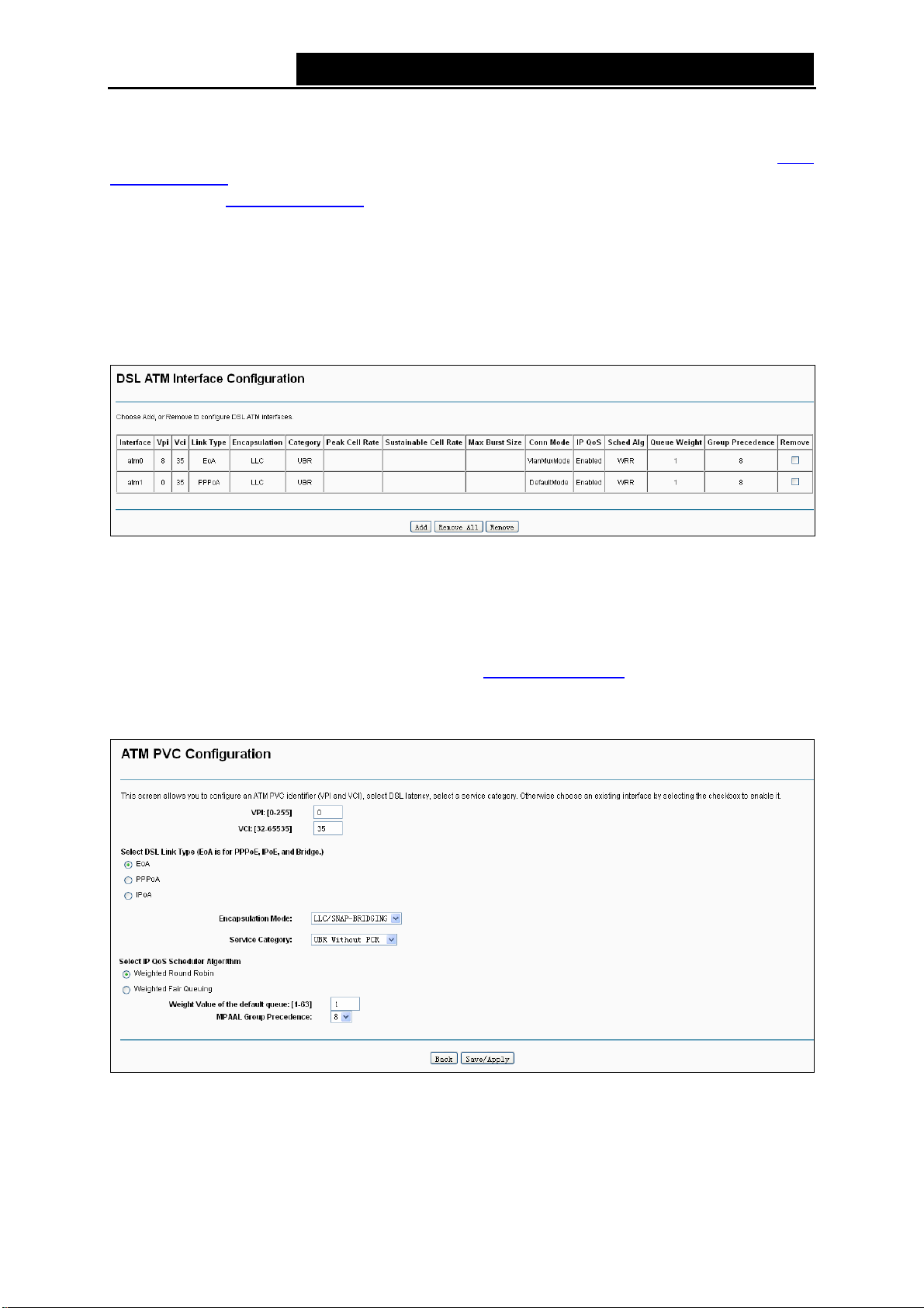
Choose “Ad
interfaces on the screen below.
¾ Remove: Select the check box in the table on the screen above and then click the Remove
button, the corresponding interface will be deleted in the table.
Note:
)
the interface is used by the configuration of the 4.5.2
If
corresponding WAN Service entry first before you can remove it here.
¾ Add: Click the button, and you can add a new interface in the next screen.
vanced Setup”Æ“Layer2 Interface“Æ“ATM Interface”, you can Configure ATM
Figure 4-
3
WAN Service, you need to r
emove the
Figure 4-
¾ VPI/VCI: the VPI and VCI values provided by your ISP. Do not change them unless it was
required by your ISP.
4
18
Page 31

TD-W89
68 300Mbps Wireless N USB ADSL2+ Modem Router User Guide
¾ DSL Link T
EoA (it is for PPPoE, IPoE, and Bridge), PPPoA (PPP over ATM) and IPoA (IP over ATM).
¾ Encapsulation Mode: The mode of the data processing over the Link Type you have
selected. Uses the default setting, if you are not sure.
¾ Service Category: Select the type of the service assigned by your ISP in the drop-down list.
The default type is UBR Without PCR.
Note:
)
Enabling pa
While QoS consumes system resources; therefore the number of PVC(s) will be reduced. Besides
this, it cannot be set for the connection type of CBR and Real-time VBR. If you select the QoS
service, the Quality of Service menu will be added to the Web-based Utility, the detailed
configuration will be described in 4.4.9 Quality of Service
4.5.1.2 ETH Interface
If your modem router works on Wireless Route
InterfaceÆETH Interface”, you can see ETH WAN interface on the screen below.
ype: Select a DSL Link Type which is provided by your ISP. The options include
cket level QoS for PVC improves performance for selected classes of applications.
.
r Mode, choose “Advanced Setup”Æ“Layer2
Figure 4-
4.5.1.3 USB 3G Interface
If you enable 3G as backup access or your modem router works on 3G Router Mode, choose
“Advanced Setup”Æ“Layer2 Interface”Æ”USB 3G Interface”, you can see USB 3G interface
status on the screen below.
Figure 4-
5
6
4.5.2 WAN Service
Choose “Ad
the screen similar to Figure 4-7, which describes the WAN port settings and the relevant
manipulation to each interface. After you add a new Lay2 Interface, please follow the instructions
below to complete the further configuration of WAN Interface. There are five different
configurations for the connection types, which are PPPoE, IPoE, Bridge, PPPoA, and IPoA. You
can select the corresponding types according to your needs.
vanced Setup”Æ“WAN Service”, and you will see the WAN Port Information Table in
19
Page 32

TD-W89
Note:
)
The followin
connection types, if you need to change the configuration of ATM PVC (VPI/VCI), you should go to
the previous section (4.5.1
4.5.2.1 ATM-EoA-PPPoE
If your ISP provides a PPPoE connection and you need to use an ATM Interface, follow the steps
below to add a WAN service over a selected ATM interface:
g section adopts different VPI, VCI to introduce further configuration for the different
68 300Mbps Wireless N USB ADSL2+ Modem Router User Guide
7
gain.
Laye
r2 Interface
Figure 4-
) to configure them a
1. Add a new ATM interface and select EoA option for DSL Link Type (4.5.1.1
2. Click
3. Select the WAN service type in Figure 4-9. If your ISP provides a PPPoE connection, select
the Add button on the screen Figure 4-7 and you will enter the next screen as shown in
Figure 4-8. Click Next.
Figure 4-
PPPoE option. You can create a service name for the Service Description or leave it the
default name. Click Next.
8
ATM Interface).
20
Page 33

TD-W89
68 300Mbps Wireless N USB ADSL2+ Modem Router User Guide
Figure 4-
4. Enter the following param eters and the n click Next.
9
Figure 4-
¾ PPP Username/Password: Enter the User Name and Password provided by your ISP.
These fields are case-sensitive.
¾ PPPoE Service Name: Enter the Service Name if it was provided by your ISP. If you leave it
blank, the default name will be the same as the Service Description on the previous screen.
10
21
Page 34

TD-W89
68 300Mbps Wireless N USB ADSL2+ Modem Router User Guide
¾ Authenticati
default method is AUTO, and you can leave it as a default setting.
Note:
)
If you are no
select these options.
¾ MTU Size: Maximum Transmission Unit Size. Check this box then you can change the MTU
size. The default MTU value is 1480 Bytes. It is not recommended that you change the default
value unless required by your ISP.
¾ Enable Fullcone NAT: It is a type of NAT, if not enabled, the default NAT will act.
¾ Dial on demand (with idle timeout timer): The modem router will cut off the Internet
connection after it has been inactive for a specific period of time (idle timeout), and it will
automatically re-establish the connection as soon as you attempt to access the Internet again.
If your Internet is charged by time you may want to select this option in order to save money.
¾ PPP IP extension: Select this option to get the public IP address from the PPP server to your
PC, and the NAT and SPI Firewall will be closed. Sometimes you can think it as bridge while
PPP dialing in the modem router. It’s a special feature deployed by some ISP. Unless your ISP
specifically requires this setup, do not select it.
¾ Use Static IPv4 Address: If your ISP gives you a static WAN, Gateway and DNS IP address,
select this option to enter them manually.
on Method: Select the Authentication Method from the drop-down list, the
t sure about the PPP IP extension and PPP Debug Mode etc. below, please don’t
¾ Enable PPP Debug Mode: Select this option to debug the PPP function and you can see
many PPP log information in the System Log. Only PPP has this debug Mode.
¾ Bridge PPPoE Frames Between WAN and Local Ports: Select this option to start PPP
connection in your local PC.
¾ Enable IGMP Multicast Proxy: IGMP (Internet Group Management Protocol) is used to
manage multicasting on TCP/IP networks. Some ISPs use IGMP to perform remote
configuration for client devices, such as the router. The default value is disabled, and if you are
not sure, please contact your ISP or just leave it.
5. Select a preferred wan interface as the system default gateway in Figure 4-11 and click Next.
Figure 4-
6. Configure the DNS Server Addresses on the screen below and click Next.
11
22
Page 35

TD-W89
¾ Select DNS Server Interface from available WAN Interfaces: You can select this option to
automatically get DNS server information from the selected WAN interface.
¾ Use the following Static DNS IP Address: You can select this option to manually enter the
primary and /or optional secondary DNS server IP addresses provided by your ISP.
68 300Mbps Wireless N USB ADSL2+ Modem Router User Guide
Figure 4-
12
Note:
)
If only single
7. On the next screen you will see the detailed settings you’ve made. Please click the
Save/Apply button to save these settings.
8. On the next screen you will see the WAN Port Information Table with the new configuration.
PVC with IPoA is configured, you must enter static DNS server IP addresses.
Figure 4-
13
23
Page 36

TD-W89
¾ Remove All: Click Remove All, then all the interface in the table will be deleted.
¾ Remove: Select the check box in the table above and then click Remove, the corresponding
interface will be deleted in the table.
4.5.2.2 ATM-EoA-IPoE
If your ISP provides an IPoE connection and you need to use an ATM Interface, follow the steps
below to add a WAN service over a selected ATM interface:
68 300Mbps Wireless N USB ADSL2+ Modem Router User Guide
Figure 4-
14
1. Add a new ATM interface and select EoA option for DSL Link Type (4.5.1.1
2. Click
3. If your ISP provides an IPoE connection, select IPoE option for the WAN service type on the
4. Enter parameters in the following bla nks to configure the WAN IP Address and click Next.
the Add button on the screen (as shown Figure 4-7). Select WAN Service Interface over
ATM PVC on the next screen (as shown Figure 4-8).
screen (as shown Figure 4-9), and click Next button to continue.
ATM Interface).
Figure 4-
¾ Obtain an IP address automatically: Select this option, the modem router will be able to
obtain IP network information dynamically from a DHCP server provided by your ISP.
Note:
)
The response message from a DHCP server typically contains a number of configuration
1)
parameters (DHCP options) for the modem router. The DHCP options include IP network
15
24
Page 37

TD-W89
68 300Mbps Wireless N USB ADSL2+ Modem Router User Guide
information, and also the vendor-sp
implemented to perform user-defined operations (as shown below). You can implement your
own treatment of all such options.
2) If the modem router is functioning as a DHCP client, it must identify itself in option 61
(client-identifier) in every DHCP message. DUID/IAID is portion of option 61.
• Option 60 Vendor ID: The option code 60 used to identify Vendor class.
• Option 61 IAID: IAID (Identity Association ID) assigns an Identity Association ID to
individual interfaces. In cases where the device is functioning with a single DHCP client
identity, it must use value 1 for IAID for all DHCP interactions. In cases where the device
is functioning with multiple DHCP client identities, the values of IAID have to start at 1 for
the first identity and be incremented for each subsequent identity. For example, the
device may use IAID value 1 for the first physical interface and value 2 for the second.
Alternatively, the device may use IAID value 1 for the virtual circuit corresponding to the
first connection object in the data model and value 2 for the second connection object in
the data model.
• Option 61 DUID: Specifies the name of the interface whose link-layer address the server
is to use as its DUID (DHCP Unique Identifier). You must enter a value for this parameter
or the server will not start. When the server starts, the DUID is written to the system log.
• Option 125: The option 125 allows DHCP server to be pre-configured with policy for
handling classes of devices in a certain way without requiring DHCP server to be able to
parse the unique format used in client-identifier option.
ecific options. In some cases, the modem router is
¾ Use the following Static IP address: If you are provided with a static IP/gateway Address,
please select this option, and then enter the WAN IP Address, WAN Subnet Mask and WAN
gateway IP Address manually.
5. You will see the next screen as below. You can enable the NAT, SPI Firewall, and IGMP
Multicast, if you are not sure about the settings, just leave the default settings. Click Next.
Figure 4-
¾ Enable NAT: This technology translates the IP addresses of a local area network to a
different IP address for the Internet. If this modem router is hosting your network’s connection
to the Internet, please select the check box. If another router exists in your network, you don’t
need to select the option.
16
¾ Enable Firew
firewall, or else without a firewall.
all: A SPI firewall enhances network’s security. Select the option to use a
25
Page 38

TD-W89
68 300Mbps Wireless N USB ADSL2+ Modem Router User Guide
¾ Enable IGMP Multicast:
Group Management Protocol) packets to be forwarded to the LAN. IGMP is used to manage
multicasting on TCP/IP networks. Most users will not need to enable this. Some ISPs use
IGMP to perform remote configuration for client devices, such as the router. If you are unsure,
check with your ISP.
Note:
)
If you select the Enable N
will describe the detailed configuration in 4.5.6
6.
Select a preferred WAN interface as the system default gateway and click Next.
This is disabled by default. This setting will not allow IGMP (Internet
AT checkbox, the NAT menu will be added to the Web-based Utility. We
NAT.
Figure 4-
7. Configure the DNS Server Addresses on the screen as follows.
17
Note:
)
If only single
Figure 4-
PVC with IPoA is configured, you must enter static DNS server IP addresses.
18
26
Page 39

TD-W89
8.
On the next screen (as shown Figure 4-19) you will see the detailed settings you’ve made.
Please click the Apply/Save button to save these settings.
68 300Mbps Wireless N USB ADSL2+ Modem Router User Guide
Figure 4-
4.5.2.3 ATM-EoA-Bridging
If you want to adopt the Bridge service and you need to use an ATM Interface, follow the steps
below to add a WAN service over a selected ATM interface:
1. Add a new ATM interface and select EoA option for DSL Link Type (see 4.5.1.1
Interface).
2. Click
3. Select Bridging option for the WAN service type on the screen (as shown Figure 4-9), and
4. On the screen (as shown Figure 4-13) you will see the detailed settings you’ve made. Please
4.5.2.4 ATM-PPPoA
If your ISP provides a PPPoA connection and you need to use an ATM Interface, follow the steps
below to add a WAN service over a selected ATM interface:
1. Add a new ATM interface and select PPPoA option for DSL Link Type (see
the Add button on the screen Figure 4-7. Select WAN Service Interface over ATM PVC
on the next screen (as shown Figure 4-8).
click Next button to continue.
click the Apply/Save button to save these settings.
Interface).
19
ATM
4.5.1.1 ATM
2. Click
4.5.2.5 ATM-IPoA
If your ISP provides an IPoA connection and you need to use an ATM Interface, follow the steps
below to add a WAN service over a selected ATM interface.
1. Add a new ATM interface and select IPoA option for DSL Link Type (see 4.5.1.1
the Add button on the screen Figure 4-7 and the next configuration is similar to PPPoE,
(see section 4.5.2.1
PPPoE Service Name and Bridge PPPoE Frames Between WAN and Local Ports on the
screen of Figure 4-10.
Interface).
AT
M-EoA-PPPoE
). The difference is that you d
27
on’t need to set the
ATM
Page 40

TD-W89
68 300Mbps Wireless N USB ADSL2+ Modem Router User Guide
2. Click
)
ETH and ATM
any other WAN service over the ETH Interface until the ATM Interface is deleted.
4.5.2.6 ETH-PPPoE
If your ISP provides a PPPoE connection, click the Add button on the screen Figure 4-7 and the
following configuration is similar to PPPoE over ATM interface (see section 4.5.2.1
ATM-EoA-P
4.5.2.7 ETH-IPoE
If your ISP provid
next configuration is similar to IPoE over ATM interface (see section 4.5.2.2
4.5.2.8 ETH-Bridge
the Add button on the screen Figure 4-7 and the next configuration is similar to IPoE
(see section 4.5.2.2
Static IP Address on the screen of Figure 4-15, and the Static IP Address for DNS Server on
the screen of Figure 4-18.
Note:
service can not coexist. If the ATM Interface had configured, you cannot configure
).
PPoE
es an IPoE connection, click the Add button on the screen Figure 4-7 and the
ATM-EoA-IPoE). The differ
ence is that you have to manually set the
ATM-EoA-IPoE).
If you want t
configuration is similar to Bridge over ATM interface (see section 4.5.2.3
o adopt the Bridge service, click the Add button on the screen Figure 4-7 and the next
M-EoA-Bridg
AT
).
4.5.3 3G Settings
Choose men
on the screen below. To use the 3G function, you should first insert your USB modem on the USB
port of the modem router. There is already much 3G USB modem information embedded in the
modem router. The USB modem parameters will be set automatically if the card is supported by
the modem router. If your USB modem inserted is supported by the modem router, then “Identify
successfully” will display in the USB 3G Modem field as shown in Figure 4-20.
Some 3G USB modem may not be supported by the modem router. For more information, please
refer to Compatibility List on our website: www.tp-link.com
incompatible with our modem router, please feel free to contact our technical support.
u “Advanced Setup→3G Settings”, you can configure parameters for 3G function
. If your 3G USB modem is
28
Page 41

TD-W89
68 300Mbps Wireless N USB ADSL2+ Modem Router User Guide
Figure 4-
20
¾
Location: The location where you'
¾
Mobile ISP: The ISP (Internet Servic
router will show the default Dial Number and APN of that ISP.
Note:
)
our Location or Mobile ISP is not listed, please untick the box before Automatically fill
If y
ISP Information. Then fill the Dial Number and APN blanks below.
Dial on de
¾
pre-specified period of time (Inactivity Timeout), the connection will drop down automatically.
And once there is traffic send or receive, the connection will be automatically on. If you want
your Internet connection to remain active at all times, enter 0 in the Inactivity Timeout field.
)
Sometimes
Timeout because some applications visit the Internet continually in the background.
¾ Connect/Disconnect: Yo
connection immediately.
¾
Authenticati
with your ISP or keep it Auto.
mand: Dial on demand is dependent on the traffic. If there is no traffic (or Idle) for a
Note:
the connection cannot be disconnected although you specify a time to Inactivity
u can click the Connect/Disconnect button to connect/disconnect
on Method: Some ISPs need a specific authentication type, please confirm it
re enjoying the 3G card.
e Provider) you apply to for 3G service. The modem
MTU size(in
¾
is usually fine. For some ISPs, you need modify the MTU. This should not be done unless you
are sure it is necessary for your ISP.
Note:
)
3G settings is unavaila
enabled. Please tick the box in the next screen to enable 3G as a backup solution for Internet
access or change settings on Operation Mode if you want to use 3G.
bytes): The default MTU (Maximum Transmission Unit) size is 1480 bytes, which
ble when operation mode is not 3G Router Mode and the backup is not
29
Page 42

TD-W89
68 300Mbps Wireless N USB ADSL2+ Modem Router User Guide
Figure 4-
Click Modem Settings in Figure 4-20, 3G Modem settings can be shown as below.
Figure 4-
To upload 3G USB Modem Configuration File:
1. Click the Add button. Then Figure 4-23 will pop up.
2. Click the Browse button in Figure 4-23, and then select the right file from the drop-down list.
Click the Upload Settings button to upload the file.
21
22
Figure 4-
Click Show Advanced Settings in Figure 4-20, advanced settings can be shown as below.
30
23
Page 43

TD-W89
68 300Mbps Wireless N USB ADSL2+ Modem Router User Guide
24
PPP Username/Pass
¾
Figure 4-
word: Enter the Username and Password provided by your ISP. These
fields are case-sensitive.
¾
Use Sta
tic IPv4 Address: If your ISP specifies an IP address for you, click the checkbox and
fill the Static IPv4 Address.
Use Static
¾
DNS IP Address: If your ISP specifies a DNS IP address for you, click the
checkbox and fill the Primary DNS and Secondary DNS blanks below. The Secondary DNS
is optional. Otherwise, the DNS servers will be assigned dynamically from ISP.
¾ Primary
Secondar
¾
DNS: Enter the DNS IP address in dotted-decimal notation provided by your ISP.
y DNS: (Optional) Enter another DNS IP address in dotted-decimal notation
provided by your ISP.
Once the connection is successful, you will find the 3G screen is similar to Figure 4-20. Click menu
“Device Info”Æ“WAN” and you will see the 3G status is similar to Figure 4-25.
Figure 4-
25
Click the Save button to save your settings.
4.5.4 MAC Clone
Choose men
WAN Interface as shown below.
The WAN Interface List displays the Lay2 Interfaces you have configured on the section 4.5.1
r2 Interface
Laye
Service for the interface on the section 4.5.2
d a corresponding WAN Service”.
“Nee
The last one of WAN Interface List displays your PC’s current address.
u “Advanced Setup”Æ“MAC Clone”, you can configure the MAC address of the
and its
default MAC Address. If you have not configured corresponding WAN
WAN Service, the blank for MAC Address will display
31
Page 44

TD-W89
Type the new value for the WAN Interface who’s MAC Address you want to change.
You can select corresponding WAN Interface from the drop-down list and click Clone button to
clone your current PC MAC.
Click Restore Default button to restore the WAN Interface’s default MAC Address.
Note:
)
68 300Mbps Wireless N USB ADSL2+ Modem Router User Guide
Figure 4-
26
Only the WA
be the same with each other.
N Ports can use MAC Address Clone function. All the clone MAC addresses must not
4.5.5 LAN
Choose “Advanced Set
and IPv6 LAN Config. The section allows you to configure the modem router’s LAN ports settings.
4.5.5.1 IPv4 LAN Config
Choose “Advanced Setup”Æ“LAN” Æ“IPv4LAN Config”, and you will see the LAN screen
(shown in Figure 4-27), here you can configure LAN IPv4interface for your modem router.
up”Æ“LAN”, and you will see the LAN screen including IPv4 LAN Config
32
Page 45

TD-W89
68 300Mbps Wireless N USB ADSL2+ Modem Router User Guide
Figure 4-
¾ IP Address: You can configure the modem router’s IP Address and Subnet Mask for LAN
Interface.
• IP Address: Enter the modem router’s local IP Address, then you can access to the
Web-based Utility via the IP Address, the default value is 192.168.1.1.
• Subnet Mask: Enter the modem router’s Subnet Mask, the default value is 255.255.255.0.
¾ Enable IGMP Snooping: If you select the option, please choose the IGMP Mode: Standard
Mode or Blocking Mode.
¾ DHCP Server: These settings allow you to configure the modem router‘s Dynamic Host
Configuration Protocol (DHCP) server function. The DHCP server is enabled by default for the
modem router’s Ethernet LAN interface. DHCP service will supply IP settings to computers
which are configured to automatically obtain IP settings that are connected to the modem
router though the Ethernet port. When the modem router is set for DHCP, it becomes the
default gateway for DHCP client connected to it. Keep in mind that if you change the IP
address of the modem router, you must change the range of IP addresses in the pool used for
DHCP on the LAN.
• Start IP Address: Enter a value for the DHCP server to start with when issuing IP
addresses. Because the default IP address for the modem router is 192.168.1.1, the
default Start IP Address is 192.168.1.2, and the Start IP Address must be 192.168.1.2 or
greater, but smaller than 192.168.1.254.
27
• End IP Address: Enter a value for the DHCP server to end with when issuing IP
addresses. The End IP Address must be smaller than 192.168.1.254. The default End IP
Address is 192.168.1.254.
33
Page 46

TD-W89
68 300Mbps Wireless N USB ADSL2+ Modem Router User Guide
• Leased Time (hour): The Leased Time is
be allowed connection to the modem router with their current dynamic IP address. Enter
the amount of time, in hours, then the user will be “leased” this dynamic IP address. After
the dynamic IP address has expired, the user will be automatically assigned a new
dynamic IP address. The default is 24 hours.
¾ Static IP Lease List: The function allows you to specify a reserved IP address for a PC on the
LAN, that PC will always obtain the assigned IP address each time when it accesses the
DHCP server. Reserved IP addresses should be assigned to servers that require permanent
IP settings. Click the Add button in Figure 4-27, and then you will set the rule in the screen as
below.
the amount of time in which a network user will
Figure 4-
• MAC Address: The MAC address of the computer on the LAN which you want to reserve
an IP.
• IP Address: The IP address you want to reserved to the computer.
¾ Configure the second IP Address and Subnet Mask: You can configure the modem
router’s second IP Address and Subnet Mask for LAN Interface through which you can also
access to the Web-based Utility as the default IP Address and Subnet Mask.
4.5.5.2 IPv6 LAN Config
Choose “Advanced Setup”Æ“LAN” Æ“IPv6 LAN Config”, and you will see the LAN screen
(shown in Figure 4-29), here you can configure LAN IPv6 interface for your modem router.
28
34
Page 47

TD-W89
68 300Mbps Wireless N USB ADSL2+ Modem Router User Guide
Figure 4-
¾ Interface Address (prefix length is required): Here enter the prefix length of your interface
address.
¾ IPv6 LAN Applications: Select a type to assign IPv6 addresses to the computers in your
LAN. DHCPv6 Server and RADVD are provided.
For DHCPv6 Server:
1) If Stateless is selected, it doesn’t need to be configured.
2) If Stateful is selected, please complete the following parameters.
• Start interfa
addresses.
ce ID: Enter a value for the DHCPv6 server to start with when issuing IPv6
29
• End interface ID: Enter a value for the DHCPv6 server to end with when issuing IPv6
addresses.
• Leased Time (hour): The Leased Time is the amount of time in which a network user will
be allowed to connect to the modem router with their current dynamic IPv6 address.
Enter the amount of time, in hours, then the user will be “leased” this dynamic IPv6
address. After the dynamic IPv6 address has expired, the user will be automatically
assigned a new dynamic IPv6 address. The default is 24 hours.
35
Page 48

TD-W89
68 300Mbps Wireless N USB ADSL2+ Modem Router User Guide
For RADVD:
1) If Randomly Generate is selected, it doesn’t need to be configured.
2) If Statically Configure is selected, please complete the following parameters.
• Prefix: Enter
Click Save/Apply to make the configuration take effect.
a value for the site prefix.
4.5.6 NAT
NAT (Network Address
address for multiple computers on your LAN (Local Area Network).
Note:
)
When yo
type of IPoA and IPoE connection (4.5.2
Web-based Utility.
Choose “Advanced Setup”Æ“NAT”, there are three submenus under the main menu: Virtual
Servers, Port Triggering, DMZ Host and ALG. Click any of them, and you will be able to
configure the corresponding function.
4.5.6.1 Virtual Servers
Choose “Advanced Setup”Æ“NAT”Æ“Virtual Servers”, you can set up virtual servers on the
screen below (shown in Figure 4-30).
Virtual servers can be used for setting up public services on your LAN, such as DNS, Email and
FTP. A virtual server is defined as a service port, and all requests from the Internet to this service
port will be redirected to the computer specified by the server IP. Any PC that was used for a
virtual server must have a static or reserved IP Address because its IP Address may change when
using the DHCP function.
u select PPPoA or PPPoE for the WAN Setup, or when you select Enable NAT for the
Translation) allows you to share one WAN (Wide Area Network) IP
WAN Service), you will see
the NAT menu in the
36
Page 49

TD-W89
¾ Virtual Server Table: The table indicates the information about the Virtual Server entries.
• Server Name: This is the name of the Virtual Server. It is exclusive and must be filled in.
• External Port Start: The base number of External Ports. You can type a service port or
leave it blank.
• External Port End: The end number of External Ports. You can type a service port or
leave it blank.
• Protocol: The protocol used for this application, TCP, UDP, or TCP/UDP.
68 300Mbps Wireless N USB ADSL2+ Modem Router User Guide
Figure 4-
30
• Internal Port Start: The base number of Internal Ports. You can type a service port or
leave it blank.
• Internal Port End: The end number of Internal Ports. You can type a service port or leave
it blank.
• Server IP Address: The IP Address of the PC providing the service application.
• WAN Interface: The WAN Service Interface providing the service application.
¾ Add: Click the Add button to add a new entry.
¾ Remove: Select the check box in the table (shown in Figure 4-30) and then click the Remove
button, then the corresponding entry will be deleted in the table.
To add a virtual server entry:
1. Click the Add button on the preceding screen Figure 4-30, and then you will see the new
Virtual Server in the next screen as shown in Figure 4-31.
37
Page 50

TD-W89
68 300Mbps Wireless N USB ADSL2+ Modem Router User Guide
Figure 4-
2. Select the Interface which you want to use from the drop-down list.
3. Select the service which you want to use from the drop-down list. If the list does not have the
service you need, type the name of the custom service in the text box.
4. Type the IP Address of the computer in the Server IP Address text box.
5. Enter the External Port Start, External Port End, Internal Port Start and Internal Port End in
the table, and then select the protocol used for this Virtual Server, TCP, UDP or All.
6. Click Save/Apply to enable virtual server and then you will see your setting as shown in
Figure 4-30.
Note:
)
If you select the
Internal Port Start, Internal Port End and the Protocol will be added in the table automatically. You
only need to enter the Server IP Address for the Virtual Server.
4.5.6.2 Port Triggering
Choose “Advanced Setup”Æ“NAT”Æ“Port Triggering”, you can set Port Triggering on the
screen (shown in Figure 4-32).
service from the drop-down list, the External Port Start, External Port End,
31
38
Page 51

TD-W89
68 300Mbps Wireless N USB ADSL2+ Modem Router User Guide
Some applications requir
e that specific ports in the modem router's firewall should be opened for
access by remote devices. Port Trigger dynamically opens up the 'Open Ports' in the firewall when
an application on the LAN initiates a TCP/UDP connection to a remote device using the triggering
ports. The modem router allows the remote party from the WAN side to establish new connections
back to the application on the LAN side using the open ports. A maximum 32 entries can be
configured.
Figure 4-
32
¾ Port Triggering Table: The table indicates the information about the Port Triggering entries.
• Application (Name): Thi
s is the name of the Port Triggering. It is exclusive and must be
filled.
Trigger: It
•
•
Open: It includes the Protocol and the Start and En
•
WAN Interfa
includes the Protocol and the Start and End value of the Trigger Ports.
d value of the Open Ports.
ce: The WAN Service Interface setting the Port Triggering.
¾ Add: Click the button to add a new entry.
¾ Remove: Select the check box in the table (shown in Figure 4-32) and then click the Remove
button, then the corresponding entry will be deleted in the table.
To add a new Port Triggering:
1. Click the Add button in Figure 4-32, and then you will see the new Port Triggering in the next
screen as shown in Figure 4-33.
39
Page 52

TD-W89
68 300Mbps Wireless N USB ADSL2+ Modem Router User Guide
Figure 4-
33
2. Select the application from the drop-down list. If the list does not have the application that
you want, select the Custom application radio button, and type the name of the custom
application in the text box.
3. Enter the Trigger Port Start, Trigger Port End, Open Port Start and Open Port End in the
table, and then select the Trigger protocol and Open protocol, TCP, UDP or All.
4. Click Save/Apply to enable the settings and then you will see your settings as shown in
Figure 4-32.
Note:
)
If you select the application from the
Internal Port Start, Internal Port End and the Protocol will be added in the table automatically.
4.5.6.3 DMZ Host
Choose “Advanced Setup”Æ“NAT”Æ“DMZ Host”, you can set up DMZ Host on the screen
(shown in Figure 4-34).
The DMZ host feature can make a local host be exposed to the Internet for a special-purpose
service, such as online gaming or video conferencing.
drop-down list, the External Port Start, External Port End,
40
Page 53

TD-W89
To add a new DMZ Host:
You can enter the computer's IP address and then click Save/Apply to activate the DMZ host you
set on this page.
Note:
)
DMZ host fo
have its DHCP client function disabled and should have a new static IP Address assigned to it
because its IP Address may change while using the DHCP function.
rwards all the ports at the same time. Any PC whose port is being forwarded must
68 300Mbps Wireless N USB ADSL2+ Modem Router User Guide
Figure 4-
34
4.5.6.4 ALG
Choose “Advanced Setup”Æ“NAT”Æ“ALG”, and then you can configure the basic security in the
screen as shown in Figure 4-35.
Figure 4-
Click the Save/Apply button to save your settings.
4.5.7 Securit
y
35
Choose “Ad
Filtering and MAC Filtering (only effective in Bridging mode) submenus.
4.5.7.1 IP Filtering
The IP address filtering feature makes it possible for administrators to control user's access to the
Internet, which is based on user's IP. The IP address filtering here means Outgoing, the detailed
descriptions are provided below.
vanced Setup”Æ“Security”, and you will see the security screen including IP
41
Page 54

TD-W89
68 300Mbps Wireless N USB ADSL2+ Modem Router User Guide
Choose “Ad
rules on the screen (shown in Figure 4-36).
The Outgoing IP Filtering feature allows you to control some IP traffic from LAN to access to some
specifically addresses. By default, all outgoing IP traffic from LAN is allowed, but some IP traffic
can be BLOCKED by setting up filters.
Set up an Outgoing IP Filtering rule:
1. Click the Add button in Figure 4-36, and you will see the next screen as shown in Figure 4-37.
vanced Setup”Æ“Security”Æ“IP Filtering”, you can configure Outgoing Filtering
Figure 4-
36
Figure 4-
2. Enter the Filter name for the rule, it is exclusive and must be filled.
3. Select the protocol: TCP/UDP, TCP, UDP or ICMP in the drop-down list for the connection
between the Source IP address and Destination IP address.
4. Enter a Source IP Address in dotted-decimal notation format and then type Source Port
(port or port: port) in the text boxes separately.
5. Enter a Destination IP Address in dotted-decimal notation format and then type Destination
Port (port or port: port) in the text boxes separately.
6. Click Save/Apply to save this entry.
Note:
)
When you a
preceding screen except the Filter name. If you leave the Protocol blank, it means that the rule is
effective to all protocols, if you leave the Source IP Address and/or Destination IP Address blank,
it suggests that all Source IP Addresses and/or Destination IP Addresses are controlled by the
rule, if you leave the Source Port and/or Destination Port blank, it suggests that all Source Ports
and/or Destination Ports are controlled by the rule.
dd an Outgoing IP Filtering entry, you must configure at least one condition on the
37
42
Page 55

TD-W89
4.5.7.2 MAC Filtering
68 300Mbps Wireless N USB ADSL2+ Modem Router User Guide
Choose “Ad
on the screen as shown in Figure 4-38. The section allows you to control access to the Internet by
users on your local network based on their MAC Address.
Note:
)
MAC Filtering is only effe
vanced Setup”Æ“Security”Æ“MAC Filtering”, you can configure MAC Filtering rules
ctive on ATM PVC(s) configured in Bridging mode.
Figure 4-
38
¾ Change Policy: There are two policies for the MAC filters: FORWARDED and BLOCKED.
Select the Change checkbox and click the Change Policy button to change from one policy
to another. When you set FORWARDED, it means that all MAC layer frames will be
forwarded except those matching with any of the specified rules in the table (shown in Figure
4-38). While BLOCKED means that all MAC layer frames will be blocked except those
matching with any of the specified rules in the preceding table.
¾ Add: Click the Add button, and then you can add a new MAC Filter in the next screen (shown
in Figure 4-38).
¾ Remove: Select the check box in the table (shown in Figure 4-38) and then click the Remove
button, and then the corresponding entry will be deleted in the table.
To add a MAC Filtering rule:
1. Click the Add button in Figure 4-38, and you will see the next screen similar to in Figure 4-39.
Figure 4-
2. Select Protocol Type in the drop-down list for the rule.
39
43
Page 56

TD-W89
68 300Mbps Wireless N USB ADSL2+ Modem Router User Guide
3. Enter Destin
4. Select Frame Direction in the drop-down list for the rule.
5. Select the WAN interfaces from the drop-down list.
6. Click Save/Apply to save this entry and then you will see your settings as shown in Figure
4-38.
ation MAC Address and Source MAC Address in the text box.
4.5.8 Parental Control
Choose “Ad
including Time Restriction and URL Filter. Time Restriction allows you to control the Internet
activities of the child by restricting the time of surfing. URL Filter limits every computer connected
to the modem router to access certain websites. These two features work independently.
4.5.8.1 Time Restriction
This feature allows you add time of day restriction to a special LAN device connected to the
modem router.
vanced Setup”Æ“Parental Control”, and you will see the Parental Control screen
Figure 4-
To add a Time Restriction entry:
1. Click the Add button in Figure 4-40, and then you will see the next screen as shown in Figure
4-41.
Figure 4-
2. Enter the User Name of the LAN device connected to the modem router.
40
41
3. To restrict the device where the browser is running, select the Browser's MAC Address
radio button. The MAC Address has been automatically displayed in the text box. To restrict
44
Page 57

TD-W89
68 300Mbps Wireless N USB ADSL2+ Modem Router User Guide
other LAN devices,
other LAN device.
4. Select the day to allow the rule to take effect in the table.
5. Enter the Start Blocking Time and End Blocking Time in the text box separately, and then
the device controlled will then be unable to connect to the internet during that time.
6. Click Save/Apply to save this entry and then you will see your settings as shown in Figure
4-40.
Note:
)
The Time Restriction will
Æ Internet Time”.
4.5.8.2 URL Filter
This feature allows you to configure the filter rules based on URL to control all the computers in the
LAN to access the specified port, and it is independent with Time Restriction feature.
click Other MAC Address radio button and enter the MAC address of the
not work correctly before the time of the device is set in “Management
Figure 4-
There are three policies for the URL Filter.
¾ Disable: URL Filter function will not take effect.
¾ Allow: Only allow the PCs to access the specified URL.
¾ Deny: Block the PCs to access the specified URL.
To add a URL Filter entry:
1. Check the Deny or Allow radio button. Here we take Deny for example.
2. Click the Add button in Figure 4-42 and then you will see the next screen as shown in Figure
4-43. Enter the URL Address and Port Number.
42
Figure 4-
45
43
Page 58

TD-W89
3. C
lick Save/Apply to save this entry and then you will see your settings as shown in Figure
4-42. Every computer connected to the modem router will not access this URL address on the
port.
68 300Mbps Wireless N USB ADSL2+ Modem Router User Guide
4.5.9 Quality
Choose “Ad
the screen shown in Figure 4-44. QoS helps to prioritize data as it enters your modem router. By
attaching special identification marks or headers to incoming packets, QoS determines which
queue the packets enter, based priority. This is useful when there are certain types of data you
want to give higher priority, such as voice data packets give higher priority than Web data packets.
This option will provide better service of selected network traffic over various technologies.
Select the Enable QoS checkbox to enable all QoS for all interfaces.
Select a Default DSCP Mark from drop-down list to automatically mark incoming traffic without
reference to a particular classifier.
Click Save/Apply to save the current configuration.
of Service
vanced Setup”Æ“Quality of Service”, you can enable QoS (Quality of Service) on
Figure 4-
44
Note:
)
The default DSCP mark
rules.
4.5.9.1 Queue Config
Choose “Advanced Setup”Æ“Quality of Service”Æ“Queue Config”, you can set up virtual
servers on the screen below.
is used to mark all egress packets that do not match any classification
46
Page 59

TD-W89
Click the Add button in Figure 4-45, and you can configure the QoS queue entry on the next
screen as shown in Figure 4-46.
68 300Mbps Wireless N USB ADSL2+ Modem Router User Guide
Figure 4-
45
Figure 4-
¾ Name: Set a name for the entry.
¾ Enable: Select Enable option to take this entry effect.
¾ Interface: Assigned a specific Wan Service for this QoS queue entry.
¾ Queue Precedence: Specify precedence for this QoS queue entry.
¾ DSL Latency: Select latency path for the type of data transmission, only Path0 is available for
this modem router.
After you specify the condition, click Save/Apply to save the entry and then you will see you
settings as shown in Figure 4-45.
Note:
)
Lower integer values for precedence imply higher priority for this queue relative to others.
1)
2) The queue entry configured here will be used by the classifier to place ingress packets
appropriately.
46
47
Page 60

TD-W89
4.5.9.2 QoS Classification
68 300Mbps Wireless N USB ADSL2+ Modem Router User Guide
This section will guide you to create a traffic
queue which defines the precedence and the interface and optionally overwrite the IP header
DSCP byte.
A rule consists of a class name and at least one condition below. All of the specified conditions in
this classification rule must be satisfied for the rule to take effect.
Click the Add button Figure 4-47, and you can configure the QoS on the next screen.
class rule to classify the upstream traffic, assign
Figure 4-
47
Figure 4-
After you specify the condition, click Save/Apply to save the entry.
4.5.10 Bandw
Choose “Ad
Figure 4-49. This page allows you to enable this function and to configure the value of Total
Upstream/Downstream Bandwidth.
idth Control
vanced Setup”Æ“Bandwidth Control” and then you will see the screen as shown in
48
48
Page 61

TD-W89
68 300Mbps Wireless N USB ADSL2+ Modem Router User Guide
Figure 4-
¾ Enable Bandwidth Control: Check this box to enable the Bandwidth Control function.
¾ Total Upstream Bandwidth (Kbps): Enter the upload speed through the WAN port.
¾ Total Do
¾ Save/Apply: Click this button to make the configuration take effect.
Note:
)
The Total Up
4.5.10.1 Rules List
Choose “Advanced Setup”Æ“Bandwidth Control” Æ“Rules List” and then you will see the
screen as shown in Figure 4-50. This page allows you to view and configure TC rules.
wnstream Bandwidth (Kbps): Enter the download speed through the WAN port.
stream Bandwidth and Total Downstream Bandwidth are required to be configured.
49
Figure 4-
To add a TC rule, click the Add button and you can configure it in the screen as shown in Figure
4-51.
49
50
Page 62

TD-W89
68 300Mbps Wireless N USB ADSL2+ Modem Router User Guide
Figure 4-
¾ Rule Status: Select the status of the rule from the drop-down list to enable or disable the rule.
¾ IP Range: Enter a single IP address or a range of IP addresses.
¾ Port Range: Enter a single port or a range of ports.
¾ Protocol: Select a protocol type from the drop-down list. TCP, UDP and ALL are available
here.
¾ Priority: Select priority form the drop-down list. There are five options: Highest, 1, 2, 3, 4, 5, 6
and Lowest. The default precedence of the rule is 4.
¾ Upstream: Enter the min and max upload speed through the WAN port.
¾ Downstream: Enter the min and max download speed through the WAN port.
After completing the above configuration, click the Save/Apply button to make it take effect and
then you will see the following list as shown in Figure 4-52. If you want to modify the rule, click the
Edit button. If you want to delete the rule, check the Remove box first and then click the Remove
button.
51
Figure 4-
Note:
)
The priority,
allocation of surplus upload/download bandwidth. For rules with different priority, the surplus
bandwidth is firstly allocated to the rule with the highest priority according to its max
upstream/downstream rate. If there still has surplus bandwidth, it is allocated to the rule with
hypo-high priority. For rules with the same priority, the surplus bandwidth is allocated to them
max upstream/downstream rate and min upstream/downstream rate work on
50
52
Page 63

TD-W89
68 300Mbps Wireless N USB ADSL2+ Modem Router User Guide
according to
rate is, the more bandwidth it gets.
their min upstream/downstream rate. The greater a rule’s min upstream/downstream
4.5.11 Routing
Choose “Ad
and RIP. The detailed descriptions are provided below.
4.5.11.1 Default Gateway
Choose “Advanced Setup”Æ“Routing”Æ“Default Gateway”, you can see the Default Gateway
screen.
vanced Setup”Æ“Routing”, it includes three menus: Default Gateway, Static Route
Figure 4-
4.5.11.2 Static Route
Choose “Advanced Setup”Æ“Routing”Æ“Static Route”. You can see the Static Route screen,
this screen allows you to configure the static routes (shown in Figure 4-54). A static route is a
pre-determined path that network information must travel to reach a specific host or network.
Figure 4-
To add static routing entries:
1. Click the Add button in Figure 4-54, and you will see the screen as shown in Figure 4-55.
53
54
51
Page 64

TD-W89
68 300Mbps Wireless N USB ADSL2+ Modem Router User Guide
Figure 4-
2. Enter the following data:
¾
IP Version: Select the version of IP.
¾
Destination IP Address/prefix length: The Dest
network or host that you want to assign to a static route.
Interface
¾
adopted for the Static Route.
Gate
¾
will display this item, you should type the Gateway address correctly, and the other option for
Interface will adopt the default Gateway address for the Static Route.
3. Click Save/Apply to save your settings.
Note:
)
Gatewa
4.5.11.3 RIP
Choose “Advanced Setup”Æ“Routing”Æ“RIP”, you can see the screen as shown in Figure 4-56.
: Select the Interface name in the text box, or else, the default Use Interface will be
way IP Address: If you select the IPoE or IPoA mode for Interface, the screen above
y IP address should be correctly configured if IP based Interface (IPoE, IPoA) is selected.
55
ination IP Address is the address of the
Note:
)
RIP cannot be configured
Figure 4-
on the WAN Interface which has NAT enabled (such as PPPoE).
56
4.5.12 DNS
When yo
the DNS menu which includes DNS Server and Dynamic DNS submenus.
u select the connection type PPPoE, PPPoA or IPoA for WAN configuration, you will see
52
Page 65

TD-W89
68 300Mbps Wireless N USB ADSL2+ Modem Router User Guide
4.5.12.1 DNS Server
Choose “Advanced Setup”Æ“DNS”Æ“DNS Server”, and you can see the DNS Server
Configuration screen as shown in Figure 4-57.
Figure 4-
For PPPoA, PPPoE enabled PVC(s), please select the Select DNS Server Interface from
available WAN interfaces checkbox, this modem router will accept automatically the first
received DNS assignment from the selected configured WAN interface during the connection
establishment.
For single PVC with IPoA, static IPoE protocol, please select the Use the following Static DNS IP
address checkbox, and enter the primary and /or optional secondary DNS server IP addresses
provided by your ISP.
Here you can also select a configured WAN interface for IPv6 DNS server or enter the static IPv6
DNS server Addresses provided by your ISP.
Click the Save/ Apply button to save the new configuration.
4.5.12.2 Dynamic DNS
Choose “Advanced Setup”Æ“DNS”Æ“Dynamic DNS”, you can see the Dynamic DNS screen,
this screen allows you to configure the Dynamic DNS (shown in Figure 4-58).
The modem router offers a Dynamic Domain Name System (DDNS) feature. DDNS lets you
assign a fixed host and domain name to a dynamic Internet IP Address. The Dynamic DNS service
allows you to alias a dynamic IP address to a static hostname in any of the many domains,
allowing your modem router to be more easily accessed from various locations on the Internet.
57
53
Page 66

TD-W89
68 300Mbps Wireless N USB ADSL2+ Modem Router User Guide
Figure 4-
To add a DDNS entry:
1. Click the Add button (pop-up after Figure 4-58), and then you will set the DDNS in the next
screen (shown in Figure 4-59).
58
Figure 4-
2. Select D-DNS provider in the drop-down list.
3. Enter the Hostname of the DNS Server, and select the corresponding Interface for the
DDNS, you can leave it default.
4. Type the User Name and Password for your DDNS account.
Click Save/Apply to save your settings.
59
4.5.13 DSL
Choose “Ad
to configure the DSL (shown in Figure 4-60).
vanced Setup”Æ“DSL”, you can see the DSL Settings screen, this screen allows you
54
Page 67

TD-W89
68 300Mbps Wireless N USB ADSL2+ Modem Router User Guide
Figure 4-
You can select the modulation type, phone line pair and the capability of Bitswap or SRA. After
you set them up, click Save/Apply to save the configurations.
60
4.5.14 UPnP
Choose “Ad
Play) protocol on the screen.
UPnP (Universal Plug and Play) is a distributed, open networking standard that uses TCP/IP for
simple peer-to-peer network connectivity between devices. An UPnP device can dynamically join
a network, obtain an IP address, convey its capabilities and learn about other devices on the
network. In turn, a device can leave a network smoothly and automatically when it is no longer in
use. UPnP broadcasts are only allowed on the LAN.
vanced Setup”Æ“UPnP”, you can Enable or Disable the UPnP (Universal Plug and
Figure 4-
Select the checkbox and click Save/Apply to enable the UPnP function.
61
4.5.15 Interface Grouping
Choose “Ad
bridging groups to perform as an independent network.
vanced Setup”Æ“Interface Grouping”, you can configure multiple ports to PVC and
55
Page 68

TD-W89
68 300Mbps Wireless N USB ADSL2+ Modem Router User Guide
Figure 4-
To support this feature, you must create mapping groups with appropriate LAN and WAN
interfaces using the Add button. The Remove button will remove the grouping and add the
ungrouped interfaces to the Default group. Only the default group has IP interface.
To create a new interface group:
1. Click the Add button. You can add a new interface group in the next screen.
62
Figure 4-
2. Enter a unique name for Group.
3. Select the Interface which you want to use from the drop-down list.
Note:
)
If you like
vendor ID string. By configuring a DHCP vendor ID string any DHCP client request with the
to automatically add LAN clients to a WAN Interface in the new group add the DHCP
63
56
Page 69

TD-W89
68 300Mbps Wireless N USB ADSL2+ Modem Router User Guide
specified vendor ID (DHCP option 60) will be denied an IP address from
4. Select interfaces from the available interface list and add it to the grouped interface list using
the arrow buttons to create the required mapping of the ports.
Note:
)
These clients may obtain public IP addresses.
5. C
)
If a vendor ID is configured for a specific client
to the modem to allow it to obtain an appropriate IP address.
lick Save/Apply to make the entry effective immediately.
Note:
device, please REBOOT the client device attached
the local DHCP server.
4.5.16 IP Tunnel
IPv6 tunnel is a kind of tr
to allow isolated IPv6 hosts and networks to reach each-other over IPv4-only infrastructure before
IPv6 completely supplants IPv4. It is a temporary solution for networks that do not support native
dual-stack, where both IPv6 and IPv4 run independently.
Choose “Advanced Setup”Æ“IP Tunnel”, it includes two menus: IPv6inIPV4 and IPv4inIPv6,
The detailed descriptions are provided below.
ansition mechanism to enable IPv6-only hosts to reach IPv4 services and
4.5.16.1 IPv6inIPv4
Choose “Advanced Setup”Æ““IP Tunnel”Æ“IPv6inIPv4”, you can see the 6in4 tunnel
configuration screen. This screen allows you to configure the static routes (shown in Figure 4-64).
Figure 4-
Click the Add button in Figure 4-64, and you can configure the 6in4 tunnel on the next screen as
shown in Figure 4-65.
64
Figure 4-
¾ Mechanism: 6RD, this type is used in the situation that your WAN connection is IPv4 while
LAN connection is IPv6.
65
57
Page 70

TD-W89
68 300Mbps Wireless N USB ADSL2+ Modem Router User Guide
¾ Associat
connected WAN connections can be shown in the drop-down list.
¾ Associated LAN Interface: Select a LAN connection from the drop-down list. Only the
connected LAN connections can be shown in the drop-down list.
¾ IPv4 Mask Length: The length of the selected WAN connection’s IPv4 mask.
¾ 6rd Prefix with Prefix Length: The length of the 6rd prefix.
¾ Border Relay IPv4 Address: The IPv4 address of the border relay router of 6RD tunnel.
Click Save/Apply to make the configuration take effect.
Note:
)
In this type,
the page will prompt you to delete all the IPv6 WAN connections.
4.5.16.2 IPv4inIPv6
Choose “Advanced Setup”Æ““IP Tunnel”Æ“IPv4inIPv6”. You can see the 4in6 tunnel
configuration screen, this screen allows you to configure the static routes (shown in Figure 4-66).
ed WAN Interface: Select a WAN connection from the drop-down list. Only the
there should not have any IPv6 WAN connections. If there are IPv6 WAN connections,
Figure 4-
Click the Add button in Figure 4-66, and you can configure the 6in4 tunnel on the next screen as
shown in Figure 4-67.
Figure 4-
¾ Mechanism: DS-Lite, this type is used in the situation that your WAN connection is IPv6 while
LAN connection is IPv4.
¾ Associated WAN Interface: Select a WAN connection from the drop-down list. Only the
connected WAN connections can be shown in the drop-down list.
66
67
¾ Associated LAN Interface: Select a LAN connection from the drop-down list. Only the
connected LAN connections can be shown in the drop-down list.
¾ AFTR: Enter the IPv6 address of the remote node.
58
Page 71

TD-W89
C
lick Save/Apply to make the configuration take effect.
Note:
)
68 300Mbps Wireless N USB ADSL2+ Modem Router User Guide
In this type,
the page will prompt you to delete all the IPv4 WAN connections.
there should not have any IPv4 WAN connections. If there are IPv4 WAN connections,
4.5.17 IPSec
Choose “Ad
connections on the screen as shown in Figure 4-68.
This section will guide you to configure a VPN tunnel between two TD-W8968s. The topology is as
follows.
vanced Setup”Æ“IPSec”, you can Add/Remove or Enable/Disable the IPSec tunnel
Figure 4-
68
Note:
)
You could al
up to 10 VPN tunnels simultaneously.
so use other VPN routers to set VPN tunnels with TD-W8968N. TD-W8968N supports
59
Page 72

TD-W89
68 300Mbps Wireless N USB ADSL2+ Modem Router User Guide
Click Add N
4-69.
¾ IPSec Connection Name: Enter a name for your VPN.
¾ Remote IPSec Gateway Address (IP or Domain Name): Enter the destination gateway IP
address in the box which is the public WAN IP or Domain Name of the remote VPN server
endpoint. (For example: Input 219.134.112.247 in Device1, Input 219.134.112.246 in Device
2)
ew Connection in Figure 4-68 and then you will enter the screen shown in Figure
Figure 4-
69
¾ Tunnel access from local IP addresses: Choose Subnet if you want the Whole LAN to join
the VPN network, or else choose Single Address if you want single IP to join the VPN network.
¾ IP Address for VPN: Enter the IP address of your LAN. (For example: Input 192.168.1.1 in
Device1, Input 192.168.2.1 in Device2)
¾ IP Subnetmask: Enter the Subnet mask of your LAN. ( For example: Input 255.255.255.0 in
both Device1 and Device2)
¾ Tunnel access from remote IP addresses: Choose Subnet if you want the Remote Whole
LAN to join the VPN network, or else choose Single Address if you want single IP to join the
VPN network.
¾ IP Address for VPN: Enter the IP address of the Remote LAN. ( For example: Input
192.168.2.1 in Device1,Input 192.168.1.1 in Device2)
¾ IP Subnetmask: Enter the subnetmask of the remote LAN. ( For example: Input
255.255.255.0 in both Device1 and Device2)
¾ Key Exchange Method: Select Auto (IKE) or Manual.
¾ Authentication Method: Select Pre-Shared Key (recommended).
¾ Pre-Shared Key: Input the Pre-Shared key for Authentication. (For example: Input 12345678)
¾ Perfect Forward Secrecy: PFS is an additional security protocol.
We recommend you leave the Advanced Settings as default value.
60
Page 73

TD-W89
68 300Mbps Wireless N USB ADSL2+ Modem Router User Guide
After complete the basic settings and click Save/Apply in both De
could conmmunicate with PCs in remote LAN2. (For example: You can ping the IP address of PC2
which is 192.168.2.100 in PC1)
Note:
)
The VPN Serve
Forward Secrecy settings.
Click Show Advanced Settings and then you can configure the Advanced Settings.
rs Endpoint from both ends must use the same pre-shared keys and Perfect
vice1 and Device2, PCs in LAN1
¾ Main Mode: Select
phase1.
¾ Aggressive Mode: Select Aggressive Mode to configure IKE phase1 of the VPN Tunnel to
carry out negotiation in a shorter amount of time. (Not Recommended-Less Secure)
Note:
)
The difference between the two is that aggressive mode will pass more information in fewer
packets, with
identities of the security firewall in the clear. When using aggressive mode, some configuration
parameters such as Diffie-Hellman groups, and PFS can not be negotiated, resulting in a greater
importance of having "compatible" configuration on both ends.
¾ Key Life Time:
Enter the number of seconds for the IPSec lifetime. It is the period of time to pass before
establishing a new IPSec security association (SA) with the remote endpoint. The default value is
3600.
)
If you want t
server endpoints use the same Encryption Algorithm, Integrity Algorithm, Diffie-Hellman Group
and Key Life time in both phase1 and phase2.
Note:
the benefit of slightly faster connection establishment, at the cost of transmitting the
o change the default settings of Advanced Settings, please make sure that both VPN
Main Mode to configure the standard negotiation parameters for IKE
4.5.18 Multicast
61
Page 74

TD-W89
68 300Mbps Wireless N USB ADSL2+ Modem Router User Guide
Choose “Ad
Click Apply/Save to save your settings.
vanced Setup”Æ“Multicast”, you can configure the IGMP protocol on the screen.
4.6 IPTV
Choose “IPTV”, and you
will see the screen as shown in Figure 4-71.
Figure 4-
70
Figure 4-
¾ Enable IPTV: Check this box to enable IPTV. If this checkbox is selected, please set the
following parameters as shown in the figure below. Make sure the following settings are
correct.
¾ VPI (0~255): Identifies the virtual path between endpoints in an ATM network. The valid range
is from 0 to 255. Please input the value provided by your ISP.
¾ VCI (1~65535): Identifies the virtual channel endpoints in an ATM network. The valid range is
from 1 to 65535 (1 to 31 is reserved for well-known protocols). Please input the value
provided by your ISP.
Click the Save/Apply button to save your settings.
71
62
Page 75

TD-W89
68 300Mbps Wireless N USB ADSL2+ Modem Router User Guide
4.7 W
Choose “Wir
and you will be able to configure the corresponding function. The detailed explanations for each
submenu are provided below.
ireless
eless”, there are six submenus to configure Wireless LAN settings. Click any of them,
4.7.1 Basic
Choose “Wireless”Æ”Bas
The basic settings for wireless networking are set on this screen.
ic”, you will see the screen of Wireless--Basic settings shown as below.
Figure 4-
This page allows you to configure basic features of the wireless LAN interface. You can enable or
disable the wireless LAN interface, hide the network from active scans, set the wireless network
name (also known as SSID) and restrict the channel set based on Region requirements.
¾ Enable Wireless: If you want to use wireless features, you must select “Enable Wireless”. If
you deselect “Enable Wireless” option, all the Wireless settings below will be disabled.
¾ Hide SSID Broadcast: When wireless clients survey the local area for wireless networks to
associate with, you can select this option to avoided being surveyed.
¾ Clients Isolation: Select this option to enable AP isolation function so that stations associated
to the AP will not be able to communicate with each other.
¾ Wireless Network Name: Wireless network name shared among all points in a wireless
network. The SSID must be identical for all devices in the wireless network. It is case-sensitive
and must not exceed 32 characters (use any of the characters on the keyboard). Make sure
72
63
Page 76

TD-W89
this
setting is the same for all stations in your wireless network. Type the desired SSID in the
space provided.
¾ BSSID: Show the MAC address of the modem router.
¾ Country: Restrict the channel set and transmit power.
Click Apply/Save to save your settings.
Note:
)
The country code selection is for non-US model only and is not available to all US model. Per FCC
regulation, all WiFi product marketed in US must fix to US operation channels only.
68 300Mbps Wireless N USB ADSL2+ Modem Router User Guide
4.7.2 Securit
Choose “Wireless”Æ”Securit
below. You can configure security features of the wireless LAN interface by manually setting the
network authentication or through WPS (Wi-Fi Protected Setup) method.
y
y”, you will see the screen of Wireless--Security settings shown as
Figure 4-
4.7.2.1 WPS Setup
This section will guide you to add a new wireless device to an existing network quickly by WPS (or
called QSS) method.
Note:
)
1)
This feature is available only when OPEN, WPA-PSK, WPA2-PSK or Mixed WPA2/WPA-PSK
mode is configured.
2) To build a successful connection by WPS, you should also do the corresponding configuration
of the new device for WPS function meanwhile.
73
64
Page 77

TD-W89
I. B
y PBC
If the wireless adapter supports WPS and the Push Button Configuration (PBC) method, you can
add it to the network by PBC with the following two methods. Click Push-Button, you will see the
screen as shown below.
Method One: Hardware push button.
68 300Mbps Wireless N USB ADSL2+ Modem Router User Guide
Figure 4-
74
Step 1: Press the WPS button on the back panel of the modem router.
Step 2:
Step
Press and hold the WPS button of the adapter directly for 2 or 3 seconds.
3: Wait for a while until the next screen of adapter appears. Click Finish to complete the
WPS configuration.
65
Page 78

TD-W89
68 300Mbps Wireless N USB ADSL2+ Modem Router User Guide
Figure 4-
Method Two:
Step 1: Press the WPS button on the back panel of the modem router.
2: For the configuration of the wireless adapter, please choose “Push the button on my
Step
access point” in the configuration utility of the WPS as below, and click Next.
75
66
Page 79

TD-W89
68 300Mbps Wireless N USB ADSL2+ Modem Router User Guide
Figure 4-
Step 3: Wait for a while until the next screen appears. Click Finish to complete the WPS
configuration.
76
Figure 4-
II. By PIN
If the new device supports Quick Security Setup and the PIN method, you can add it to the
network by PIN with the following two methods.
77
67
Page 80

TD-W89
Method One: Enter the PIN of wireless adapter into my modem router.
68 300Mbps Wireless N USB ADSL2+ Modem Router User Guide
Step 1:
)
The PIN code of the adap
Step 2: For the configuration of the wireless adapter, please choose “Enter a PIN into my
Select the PIN checkbox and enter the PIN code of the wireless adapter in the field under
as shown below. Then click Add Enrollee.
Figure 4-
Note:
ter is always displayed on the WPS configuration screen.
access point or a registrar” in the configuration utility of the WPS as below, and click
Next.
78
Figure 4-
Note:
)
In this example, the default PIN
Method Two: Enter the PIN of my modem router into the wireless adapter.
Step 1: Get the Current PIN code generated by the modem router as shown below. You can click
code of this adapter is 16952898 as the preceding figure shown.
Gen New PIN to get a new PIN code for modem router.
79
68
Page 81

TD-W89
68 300Mbps Wireless N USB ADSL2+ Modem Router User Guide
Figure 4-80
Step 2: For the configuration of the wireless adapter, please choose “Enter a PIN from my
access point” in the configuration utility of the WPS as below, and enter the PIN code of
the modem router into the field after “Access Point PIN”. Then click Next.
Figure 4-
4.7.2.2 Manual Setup AP
Follow the instructions below to configure security features of the wireless LAN interface manually.
You can set the network authentication method, select data encryption, specify whether a network
key is required to authenticate to this wireless network and specify the encryption strength.
81
69
Page 82

TD-W89
68 300Mbps Wireless N USB ADSL2+ Modem Router User Guide
Figure 4-
¾ Network Authentication: Select an authentication type from the drop-down list.
Note:
)
For most u
changes made to these settings may adversely affect your wireless network. Under certain
circumstances, changes may benefit performance. Carefully consider and evaluate any changes
to these wireless settings.
1. WEP
WEP is a basic encryption method offering two levels of encryption, 64-bit and 128-bit encryption.
To configure the WEP encryption, there are two ways.
• Keep the Network Authentication of Open (insecurity) and select Enabled from the WEP
Encryption drop-down list, as shown in Figure 4-83. Open (insecurity) with WEP encryption
disable allows any wireless station to associate with the access point.
• Select Shared (good) from the Network Authentication drop-down list, as shown in Figure
4-84. Shared (good) must enable WEP encryption. Network using Open or Shared
authentication with WEP encryption only allows stations using the same network key
encryption to associate with it. Follow the instructions below to configure the Shared Keys.
sers, it is recommended to use the default Wireless LAN Performance settings. Any
82
70
Page 83

TD-W89
68 300Mbps Wireless N USB ADSL2+ Modem Router User Guide
Figure 4-
83
Figure 4-84
¾ Encryption Strength: Select the appropriate level of encryption, 64-bit or 128-bit.
¾ Current Network Key: To indicate which WEP key to use, select a transmission key number.
¾ Network Key 1-4: If you want to manually enter the WEP keys, then enter them in the network
Key 1-4 fields.
Configure WEP Settings
1. Select Shared (good) from the Network Authentication drop-down list. The menu will
change to offer the appropriate settings.
2. Select 64-bit from the WEP Encryption drop-down list.
3. Select “1” from Current Network Key drop-down list.
4. Type in the password in the Network Key 1 field.
5. Click Save/Apply to save the new configuration.
71
Page 84

TD-W89
68 300Mbps Wireless N USB ADSL2+ Modem Router User Guide
Figure 4-
Note:
)
We use Net
Key “1” and enter 10 hexadecimal digits”1234567890” in the Network Key 1 for example, as
shown in Figure 4-85 above.
work Authentication Shared (good), Encryption Strength 64-bit, Current Network
85
72
Page 85

TD-W89
68 300Mbps Wireless N USB ADSL2+ Modem Router User Guide
2. WPA-Enterp
WPA security for wireless communication has been developed to overcome some of the
shortcomings of WEP. WPA combines the key generation with the authentication services of a
RADIUS server.
¾ WPA Group ReKey Interval: Enter the Key Renewal period, which tells the modem router
how often it should change encryption keys.
rise
Figure 4-
86
¾ RADIUS Server IP Address: The IP address of the RADIUS server.
¾ RADIUS Port: The port of the RADIUS server. The default number is 1812.
¾ RADIUS Key: The password of the RADIUS Server.
¾ WPA Encryption: Select the encryption you want to use: TKIP+ AES or AES (AES is an
encryption method stronger than TKIP).
Configure WPA settings
1. Select WPA from the Network Authentication drop-down list. The menu will change to offer
the appropriate settings.
2. Change the WPA Group Rekey Interval as desired.
3. Type in the IP address of the RADIUS server used in the RADIUS Server IP Address field.
4. Change the RADIUS Port if necessary.
5. Type in the password in the RADIUS Key field.
6. Use the default setting AES of WPA Encryption.
7. Click Save/Apply to save the new configuration.
73
Page 86

TD-W89
68 300Mbps Wireless N USB ADSL2+ Modem Router User Guide
Figure 4-
3. WPA-Personal
WPA-Personal requires a shared key and does not use a separate server for authentication. PSK
keys can be ASCII or Hex type.
Figure 4-
87
88
¾ Wireless Network Key: Enter the key shared by the modem router and your other network
devices. It must have 8-63 ASCII characters or 8-64 Hexadecimal digits.
¾ Click here to display: Click it to show you the WPA Pre-Shared Key.
Configure WPA-Personal settings
1. Select WPA-Personal. The menu will change to offer the appropriate settings as the picture
show above.
2. WPA-Personal requires a shared key. Type the key in the space provided. PSK keys can be
ASCII or Hex type.
3. Change the Group Key Interval as desired or use the default setting.
4. Click Save/Apply to save the new configuration.
74
Page 87

TD-W89
68 300Mbps Wireless N USB ADSL2+ Modem Router User Guide
Figure 4-
Note:
)
If you click
password you have set. In addition, it won't show the blank characters in both ends of the
password phrase.
4. WPA2-Enterprise
To configure WPA2-Enterprise settings, select the WPA2-Enterprise option from the drop-down
list. The menu will change to offer the appropriate settings. The steps of these settings are similar
to WPA settings.
the option “Click here to display”, the Figure 4-90 will pop-up, and it shows the
Figure 4-
89
90
75
Page 88

TD-W89
¾ WPA2 Preauthentication: Select Enable from the drop-down list, Stations will authenticate
with the AP during the scanning process, and once association is required, the station has
been already authenticated.
¾ Network Re-auth Interval: Enter a value in seconds as the frequency interval to enable
periodic Network Re-authentication function, while leave it blank or enter “0” to disable it.
68 300Mbps Wireless N USB ADSL2+ Modem Router User Guide
Figure 4-
91
5. WPA2-Personal
To configure WPA2-Personal settings, select the WPA2- Personal option from the drop-down list.
The menu will change to offer the appropriate settings. WPA2- Personal requires a shared key
and does not use a separate server for authentication. PSK keys can be ASCII or Hex type.
Figure 4-
6. Mixed WPA2/WPA Enterprise
92
To configure Mixed WPA2/WPA Enterprise settings, select the Mixed WPA2/WPA Enterprise
option from the drop-down list. The menu will change to offer the appropriate settings. The steps to
these settings are similar to those for WPA-PSK.
76
Page 89

TD-W89
68 300Mbps Wireless N USB ADSL2+ Modem Router User Guide
Figure 4-
7. Mixed WPA2/WPA Personal
To configure Mixed WPA2/WPA-Personal settings, select the Mixed WPA2/WPA Personal option
from the drop-down list. The menu will change to offer the appropriate settings. The steps of this
setting are the same with WPA-PSK.
93
Figure 4-
94
4.7.3 Wireless Schedule
Choose me
below. Please set the modem router’s system time first.
nu “Wireless”Æ“Wireless Schedule”, you can configure the Task Schedule as shown
77
Page 90

TD-W89
68 300Mbps Wireless N USB ADSL2+ Modem Router User Guide
Figure 4-
95
) Note:
The time you set is the period you need the wireless off.
Before configure the wireless schedule, please set system time first which refer to 4.10.5 Internet
Time, then you can enabl
Appl
¾
¾
y To: Select the day or days you need the wireless off.
Start Time, End Time: You can select all day-24 h
e or disable Wireless Schedule.
ours or you may enter the Start Time and
End Time in the corresponding field.
¾ Add: Click
this button to add your selected time to the below table.
Click the Clear Schedule button to clear your settings in the table.
Click the Save/Apply button to complete the settings.
4.7.4 MAC Filter
Choose “Wireless”Æ”M
shown as below.
AC Filter”, you will see the screen of Wireless--MAC Filter settings
Figure 4-
78
96
Page 91

TD-W89
68 300Mbps Wireless N USB ADSL2+ Modem Router User Guide
Wireless access
within your network’s RADIUS. To filter wireless users by MAC Address, either permitting or
blocking access. If you do not wish to filter users by MAC Address, select Disabled.
¾ Disabled: Select this option to disable MAC Filter function.
¾ Allow: Select this option to enable MAC Filter function that allow wireless access by the
devices listed on this screen.
¾ Deny: Select this option to enable MAC Filter function that block wireless access from the
devices listed on this screen.
¾ Add: Click this button to add the MAC Address.
¾ Remove: Select the item of the MAC Address and click this button to remove it.
When you click the Add button, the pop-up picture shown below, and then you can type the MAC
Address in the MAC Address field.
Note:
)
The form of
can be filtered by using the MAC addresses of the wireless devices transmitting
MAC Address must be “xx:xx:xx:xx:xx:xx”, like “00:13:0A:55:FF:09”.
Figure 4-
When you finished making changes to the MAC Filter List screen, click Save/Apply to save the
changes.
97
4.7.5 Wireless Bridge
Choose “Wir
shown as below. You can configure wireless bridge features of the wireless LAN interface and
click Apply/Save button to save the current configuration.
eless”Æ”Wireless Bridge”, you will see the screen of Wireless--Bridge settings
Figure 4-
¾ AP Mode: Select an AP Mode from the drop-down list. Options available are: Access Point
and Wireless Bridge.
98
79
Page 92

TD-W89
68 300Mbps Wireless N USB ADSL2+ Modem Router User Guide
• Acce
• Wireless Bridge: Also known as WDS (Wireless Distribution System), it will bridges the
¾ Bridge Restrict:
• Disabled: Select this option to disables wireless bridge restriction, that any wireless bridge
• Enabled: Select this option (as shown below) to enables wireless bridge restriction, please
• Enabled (Scan): Select this option to enables wireless bridge restriction, and it will scan
ss Point: Select this option to allow wireless stations including AP clients to access.
wireless stations which also in bridge mode to connect two or more remote LANs.
will be granted access.
enter the MAC address of the Remote Bridges that you want to connect with, and only
these Remote Bridges are granted access.
Figure 4-
the environment for APs that exist around the device. Only those selected AP will be
granted access.
99
• Refresh: Click this button to scan and display the APs.
Figure 4-
Note:
)
Only Ope
“Wireless”Æ“Security” to change authentication method to “open” or ”shared” mode first.
n or Shared authentication method support wireless bridge, you should choose
100
4.7.6 Advanced
Choose “Wir
as below.
eless”Æ”Advanced”, you will see the screen of Wireless--Advanced settings shown
80
Page 93

TD-W89
68 300Mbps Wireless N USB ADSL2+ Modem Router User Guide
Figure 4-
¾ Channel: Select the channel you want to use from the drop-down List. This field determines
which operating frequency will be used. It is not necessary to change the wireless channel
unless you notice interference problems with another nearby access point.
¾ Mode: In the drop-down list you can select “11b”, “11bg”, “11bgn” and "11n only”. “11bgn”
allows both 802.11b, 802.11g and 802.11n wireless stations to connect to the modem router.
¾ Bandwidth: Select the Bandwidth you want to use from the drop-down List. If bigger
bandwidth is selected, device could transmit and receive data with higher speed.
¾ Control Sideband: If bigger bandwidth is selected, this option will allow you select the
Control Sideband you want.
¾ Fragmentation Threshold: This value specifies the maximum size for a packet before data
is fragmented into multiple packets. If you experience a high packet error rate, you may
slightly increase the Fragmentation Threshold. Setting the Fragmentation Threshold too low
may result in poor network performance. Only minor reduction of the default value is
recommended. In most cases, it should remain at its default value of 2346.
¾ RTS Threshold: Should you encounter inconsistent data flow, only minor reduction of the
default value 2347 is recommended. If a network packet is smaller than the preset RTS
threshold size, the RTS/CTS mechanism will not be enabled. The modem router sends
Request to Send (RTS) frames to a particular receiving station and negotiates the sending of
a data frame. After receiving an RTS, the wireless station responds with a Clear to Send (CTS)
frame to acknowledge the right to begin transmission. This mechanism can provide you a
quiet communication channel by notifying other stations not to send packet for a period of
time. In most cases, keep its default value of 2347.
101
¾ DTIM Interval: This value, between 1 and 255, indicates the interval of the Delivery Traffic
Indication Message (DTIM). A DTIM field is a countdown field informing clients of the next
window for listening to broadcast and multicast messages. The countdown unit is measured
by the amounts of beacon frames received. When the modem router has buffered broadcast
or multicast messages for associated clients, it sends the next DTIM with a DTIM Interval
value. Its clients hear the beacons and awaken to receive the broadcast and multicast
messages. The default value is 1.
81
Page 94

TD-W89
68 300Mbps Wireless N USB ADSL2+ Modem Router User Guide
¾ Beacon Interval: Enter a value
indicates the frequency interval of the beacon. A beacon is a packet broadcast by the modem
router to synchronize the wireless network. The default value is 100.
¾ Transmit Power: This option will allow you to configure the wireless transmit power. High
transmit power will extend the wireless signal range of the device and make the signal
transmit more legible. Low transmit power with the smaller wireless signal range that will
decrease the probability of interrupt by other Wi-Fi device.
¾ WMM (Wi-Fi Multimedia): This function can guarantee the packets with high-priority
messages being transmitted preferentially. It is strongly recommended.
between 20-1000 milliseconds. The Beacon Interval value
4.7.7 Station info
Choose “Wi
Stations setting shown as below.
reless”Æ” Station Info”, you will see the screen of Wireless--Authenticated
Figure 4-
This page shows authenticated wireless stations and their status.
¾ MAC: Displays the connected wireless station's MAC address.
¾ Associated: Displays whether the wireless station has associated with the access point.
¾ Authorized: Displays the information of Authentication.
¾ SSID: Displays the connected wireless station's SSID.
You cannot change any of the values on this page. To update this page and to show the current
connected wireless stations, click on the Refresh button.
102
4.8 Guest Network
There
them, and you will be able to scan or configure the corresponding function. The detailed
explanations for each submenu are provided below.
are two submenus under the Guest Network menu: Basic and Station list. Click any of
4.8.1 Basic
Choose men
This feature allows you to create a separate network for your guests without allowing them to
access your main network and the computers connected to it.
u “Guest Network”Æ“Basic”, and you will see the screen as shown in Figure 4-103.
82
Page 95

TD-W89
68 300Mbps Wireless N USB ADSL2+ Modem Router User Guide
Figure 4-
103
You can enable or disable Guest Network. When you enable this function, you could set wireless
parameters for Guest Network.
Guest SSID: The guest network na
¾
me. When setting up a Guest network, it is strongly
recommended to use a name that easily distinguishes it from your primary network.
¾
Authenticati
Encry
¾
¾
Wireless Pa
ption: You can select either AES or AES+TKIP.
on Type: Select the Authentication Type from the drop-down list.
ssword: Here display the default wireless password, you can click Click here to
display to see the default wireless password, and you can also enter ASCII characters
between 8 and 63 characters or 8 to 64 Hexadecimal characters to create a new password.
¾
Group Key
Update Period: Specify the group key update interval in seconds. The value
should be 30 or above. Enter 0 to disable the update.
Allo
¾
w Guest to Access my Local Network: The guests have access to your Local Network,
but can not login the modem router’s web management interface.
¾
Allo
w Guest to Access my USB Storage: The guests can access the specified files on the
USB storage device via the function of USB Storage Sharing, but the function of
FTP Server, Media Server and Print Server are not available in Guest Network. For more
details please refer to 4.8.3 Storage Sharing
Guest Net
¾
work Isolation: This function can isolate wireless clients on your guest network
from each other. Client isolation is disabled by default.
¾
Guest Net
work Bandwidth Control: With this function, you can configure the Upstream
.
Bandwidth and Downstream Bandwidth for guest network.
Click Save/Apply to save your settings.
4.8.2 Station list
Choose me
Authorized, SSID and Interface.
nu “Guest Network”Æ“Station list”, you can see the MAC Address, Associated,
83
Page 96

TD-W89
¾
MAC: Displa
¾
Associat
Authorized:
¾
SSID: Displays the connected wireless station's
¾
You cannot change any of the values on this page. To update this page and to show the current
connected wireless stations, click on the Refresh button.
ed: Displays whether the wireless station has associated with the access point.
68 300Mbps Wireless N USB ADSL2+ Modem Router User Guide
Figure 4-
ys the connected wireless station's MAC address.
Displays the information of Authentication.
104
SSID.
4.9 USB Settings
There are six submenus under the USB Settings menu, USB Mass Storage, User Accounts,
Storage Sharing, FTP Server, Media Server an
able to configure the corresponding function.
d Print Server. Click any of them, and you will be
4.9.1 USB Mass Storage
Choose me
attached to the modem router and view volume and share properties such as share name,
capacity, status, and action, etc on this page as shown below.
nu “USB Settings → ”USB Mass Storage”, you can configure a USB disk drive
84
Page 97

TD-W89
68 300Mbps Wireless N USB ADSL2+ Modem Router User Guide
Figure 4-
Volume: Th
¾
¾
File S
Capacit
¾
Status: Indicates the
¾
be shared, while Inactive means volume can not be shared..
¾
Action: When the volum
when volume is non-shared, you can click the Activate button to share the volume.
Click Disconnect to safely remove the USB storage device that is connected to USB port.
Note:
)
Before remo
data have been saved completely. Removing device directly may cause your USB storage device
crashed.
4.9.2 User Acco
You can specify the user
page. Storage Sharing users can access the folders by entering the following URL into the
address field of your browser or Windows Explorer, such as. \\192.168.1.1. FTP Server users can
log into the FTP Server via FTP Client.
e volume name of the USB drive the users have access to.
ystem: The system of the USB drive.
y: The storage capacity of the USB driver.
shared or non-shared status of the volume. Active means volume can
e is shared, you can click the Deactivate to stop sharing the volume;
ving the USB storage device, you should click “Disconnect” to make sure that all your
unts
name and password for Storage Sharing and FTP Server users on this
105
There are five users here, which provide means to control the access to the USB mass storage by
Storage Sharing or FTP. The Super User has the right to read and write to Storage Sharing and
FTP Server.
85
Page 98

TD-W89
68 300Mbps Wireless N USB ADSL2+ Modem Router User Guide
Figure 4-
To add a new user account, please follow the steps below:
1. Choose the index from th e drop-down list of Choose Index.
2. Self-define a New Username.
3. Enter the password in the New Password field.
4. Re-enter the password in the Confirm Password field.
Click the Set button, and then a new entry will be added in the table.
106
4.9.3 Storage Sharing
Choose me
attached to the modem router and view volume and share properties on this page as shown
below.
nu “USB Settings” → ”Storage Sharing”, you can configure a USB disk drive
Figure 4-
86
107
Page 99

68 300Mbps Wireless N USB ADSL2+ Modem Router User Guide
us: Indicates the Storage Sharing's current status.
Server Stat
¾
Anon
¾
TD-W89
ymous access to all the volumes: This function is enabled by default, so users can
access all activated volumes of Storage Sharing without accounts. If you want to add a
shared folder which does not allow anonymous login, uncheck the box to disable this
function. And Folder Table will be displayed as shown below.
Share Name
¾
¾
Director
User Index: The authorization of
¾
: This folder's display name.
y: The real full path of the specified folder.
Figure 4-
the user is displayed. * users mean Super Users who have
108
the full-access permission to all activated volumes and share folders. Grey users mean the
users who have no right to use this function. Others are common users.
Status: The
¾
¾
Edit: Click Edi
status of the entry is enabled or disabled.
t in the table, and then you can modify the entry.
To add a new folder, follow the instructions below.
1. Click Add New Folder in Figure 4-108.
Figure 4-
109
2. Click the Browse button, and then select the Select Volume from the drop-down list.
3. Enter display name of the share folder in Share Name filed.
87
Page 100

TD-W89
4. C
lick the Save/Apply button to apply the settings.
You can click the upper button to go to the upper folder
Click the Enable/Disable Selected button to enable or disable the selected entries.
Click the Delete Selected button to delete the selected entries.
Note:
)
The max share folders number is 10. If you want to share a new folder when the number has
1)
reached 10, you can delete an existing share folder and then add a new one.
2) If you want to change the Storage Sharing settings, you can click the Apply button to make
the changes take effect.
68 300Mbps Wireless N USB ADSL2+ Modem Router User Guide
4.9.4 FTP Server
Choose me
accessed from the Internet or your local network.
nu “USB Settings”→ ”FTP Server”, you can create an FTP server that can be
Figure 4-
110
Server Stat
¾
¾ Internet Ac
server via Internet Address.
¾
Internet Ad
Service Port: Enter the FTP Port number to use. The default is
¾
¾ Share Name
¾ Director
User Index:
¾
Status: The
¾
¾ Edit: Click Edi
us: Indicates the FTP Server's current status.
cess: If Internet Acc ess is enabled, user(s) in public network can access FTP
dress: If Internet Access is enabled, WAN IP will be displayed here.
: This folder's display name.
y: The real full path of the specified folder.
The authorization of the user is displayed.
status of the entry is enabled or disabled.
t in the table, and then you can modify the entry.
88
21.
 Loading...