

Page 1
TL-SC4171G
Wireless Pan/Tilt Surveillance Camera
Rev: 1.0.0
1910010423
Page 2

COPYRIGHT & TRADEMARKS
Specifications are subject to change without notice. is a registered trademark of
TP-LINK TECHNOLOGIES CO., LTD. Other brands and product names are trademarks or
registered trademarks of their respective holders.
No part of the specifications may be reproduced in any form or by any means or used to make any
derivative such as translation, transformation, or adaptation without permission from TP-LINK
TECHNOLOGIES CO., LTD. Copyright © 2010 TP-LINK TECHNOLOGIES CO., LTD.
All rights reserved.
http://www.tp-link.com
Page 3

FCC STATEMENT
This equipment has been tested and found to comply with the limits for a Class B digital device,
pursuant to part 15 of the FCC Rules. These limits are designed to pro-vide reasonable protection
against harmful interference in a residential installation. This equipment generates, uses and can
radiate radio frequency energy and, if not in-stalled and used in accordance with the instructions,
may cause harmful interference to radio communications. However, there is no guarantee that
interference will not occur in a particular installation. If this equipment does cause harmful
interference to radio or television reception, which can be determined by turning the equipment off
and on, the user is encouraged to try to correct the interference by one or more of the following
measures:
Reorient or relocate the receiving antenna.
Increase the separation between the equipment and receiver.
Connect the equipment into an outlet on a circuit different from that to which the receiver is
connected.
Consult the dealer or an experienced radio/ TV technician for help.
This device complies with part 15 of the FCC Rules. Operation is subject to the following two
conditions:
This device may not cause harmful interference.
This device must accept any interference received, including interference that may cause
undesired operation.
Any changes or modifications not expressly approved by the party responsible for compliance
could void the user’s authority to operate the equipment.
CE Mark Warning
This is a class B product. In a domestic environment, this product may cause radio interference, in
which case the user may be required to take adequate measures.
Page 4

CONTENTS
Package Contents.........................................................................................................................1
Chapter 1 Safety Instruction.....................................................................................................2
Chapter 2 Minimum System Requirement & Product Feature...............................................3
2.1 System Requirement...................................................................................................3
2.2 Product Feature ..........................................................................................................3
Chapter 3 Using IP Camera via Web Browser.........................................................................7
3.1 Obtain the IP Address .................................................................................................7
3.2 Windows Web Browser ...............................................................................................8
3.3 Mac Web Browser.....................................................................................................10
Chapter 4 Using IP Camera via Mobile Phone ......................................................................13
4.1 Mobile Phone Viewing...............................................................................................13
4.1.1 3G Mobile Phone Streaming Viewing...................................................................13
4.1.2 2.5G Mobile Phone WAP Viewing ........................................................................13
4.1.3 2.5G Mobile Phone Browser Viewing...................................................................13
4.2 Using IP Camera via iPhone .....................................................................................13
Chapter 5 MSN Messenger .....................................................................................................15
Chapter 6 Configuration of Main Menu.................................................................................. 22
6.1 Live View...................................................................................................................22
6.1.1 Snapshot..............................................................................................................22
6.1.2 Zoom in / out the image via the monitor window ..................................................23
6.1.3 Video play buttons................................................................................................23
6.1.4 Audio buttons .......................................................................................................23
6.2 Setting ....................................................................................................................... 24
6.3 Client Setting.............................................................................................................24
6.3.1 Mode .................................................................................................................... 25
6.3.2 View Size .............................................................................................................25
6.3.3 Protocol................................................................................................................25
6.3.4 Video Buffer .........................................................................................................25
6.4 Image Setup..............................................................................................................25
6.4.1 Brightness ............................................................................................................25
6.4.2 Contrast ...............................................................................................................25
6.4.3 Saturation.............................................................................................................25
6.4.4 Hue ......................................................................................................................25
6.4.5 Default..................................................................................................................26
6.5 PT/PTZ Control .........................................................................................................26
6.5.1 Pan / Tilt / Home control buttons ..........................................................................26
6.5.2 Other camera control functions ............................................................................26
Chapter 7 Setting-Basic ..........................................................................................................28
7.1 System ......................................................................................................................28
7.1.1 Information ...........................................................................................................28
7.1.2 Date/Time.............................................................................................................29
7.1.3 Initialize ................................................................................................................ 30
7.2 Camera .....................................................................................................................31
Page 5

7.2.1 General ................................................................................................................31
7.2.2 MPEG-4 ...............................................................................................................33
7.2.3 MJPEG.................................................................................................................35
7.3 Network .....................................................................................................................36
7.3.1 Information ...........................................................................................................37
7.3.2 PPPoE (Point-to-Point Protocol over Ethernet)....................................................38
7.3.3 DDNS (Dynamic DNS) .........................................................................................39
7.3.4 UPnP (Universal Plug and Play) ..........................................................................43
7.3.5 Bonjour.................................................................................................................44
7.3.6 IP Notification.......................................................................................................45
7.3.7 Wireless ...............................................................................................................46
7.3.8 Messenger ...........................................................................................................49
7.4 Security .....................................................................................................................51
7.4.1 Account ................................................................................................................ 51
7.4.2 HTTPS .................................................................................................................52
Chapter 8 Setting-Advanced...................................................................................................53
8.1 PT Control .................................................................................................................53
8.2 Preset Position ..........................................................................................................54
8.3 Patrol.........................................................................................................................55
8.4 FTP Client .................................................................................................................56
8.4.1 General ................................................................................................................56
8.4.2 Alarm Sending .....................................................................................................57
8.4.3 Periodical Sending ...............................................................................................59
8.5 SMTP ........................................................................................................................60
8.5.1 General ................................................................................................................60
8.5.2 Alarm Sending .....................................................................................................62
8.5.3 Periodical Sending ...............................................................................................64
8.6 HTTP Event...............................................................................................................65
8.6.1 General ................................................................................................................65
8.6.2 Alarm Sending .....................................................................................................66
8.7 Alarm Output .............................................................................................................69
8.8 Schedule ...................................................................................................................70
8.9 Alarm Input................................................................................................................71
8.10 Motion Detection .......................................................................................................71
8.11 System Log ...............................................................................................................72
Appendix .....................................................................................................................................74
A. FRAME-RATE AND BITRATE TABLE .................................................................................74
B. STORAGE REQUIREMENT TABLE ...................................................................................76
C. TESTING SYSTEM SPECIFICATION.................................................................................79
D. PERFORMANCE OF 16 CHANNEL IP CAMERA...............................................................79
Europe – EU Declaration of Conformity ...................................................................................80
Federal Communication Commission Interference Statement...............................................81
Page 6

)
Package Contents
The following items should be found in your package:
¾ TL-SC4171G Wireless Pan/Tilt Surveillance Camera
¾ Power Adapter
¾ Camera Mount Kit & Pads
¾ Ethernet Cable
¾ Quick Installation Guide
¾ Resource CD, including:
z This User Guide
z Application Guide
z Other helpful information
Note:
Make sure that the package contains the above items. If any of the listed items are damaged or missing,
please contact your distributor.
1
Page 7

Chapter 1 Safety Instruction
¾ Before you use this product
This product has been designed with safety in mind. However, the electrical products can cause fires
which may lead to serious body injury if not used properly. To avoid such accidents, be sure to heed the
following.
¾ Legal Caution
Video and audio surveillance can be forbidden by laws that vary from country to country. Check the laws
in your local region before using this product for surveillance purposes.
¾ Don't open the housing of the product
Don't try to open the housing or remove the covers which may expose yourself to dangerous voltage or
other hazards.
¾ Don't use the accessories not recommended by the manufacturer
¾ Heed the safety precautions
Be sure to follow the general safety precautions and the “Operation Notice.”
¾ Operation Notice - Operating or storage location
Avoid operating or storing the camera in the following locations:
x Extremely hot or cold places (Operating temperature: 0 °C to + 50 °C [32 °F to 122°F] )
x Exposed to direct sunlight for a long time, or close to heating equipment (e.g., near heaters)
x Close to water (e.g., near a bathtub, kitchen sink, laundry tub)
x Close to sources of strong magnetism
x Close to sources of powerful electromagnetic radiation, such as radios or TV transmitters
x Locations subject to strong vibration or shock
¾ In case of a breakdown
In case of system breakdown, discontinue use and contact your authorized dealer.
¾ In case of abnormal operation
x If the unit emits smoke or an unusual smell,
x If water or other foreign objects enter the cabinet, or
x If you drop the unit or damage the cabinet: 1 Disconnect the cable and the connecting cables. 2
Contact your authorized dealer or the store where you purchased the product.
¾ Transportation
When transporting the camera, repack it as originally packed at the factory or in materials of equal
quality.
¾ Ventilation
To prevent heat buildup, do not block air circulation around the device.
¾ Cleaning
x Use a soft, dry cloth to clean the external surfaces of the device. Stubborn stains can be
removed using a soft cloth dampened with a small quantity of detergent solution, then wipe dry.
x Do not use volatile solvents such as alcohol, benzene or thinners as they may damage the
surface.
2
Page 8

)
)
Chapter 2 Minimum System Requirement & Product Feature
2.1 System Requirement
We strongly recommend your computers follow our minimum requirements in order to use this
IP-Camera normally. If computer level is lower than this, it might cause some problems.
Item Requirements
CPU Pentium 4 1600MHz (or equivalent AMD)
Graphic Card 64 MB RAM graphic cards(or equivalent on-board graphic cards)
RAM 512 MB
Operating System
Web Browser Internet Explore 6 or later
Note:
1. If you are using Windows 98 or Windows ME, please install IP Installer before using WEB UI to
2. If you can't view the record video file, please install Xvid codec while installing Intelligent IP Installer.
3. Please always update the latest Windows component. (.Net Framework, Windows Media Player,
ensure the system runs normally.
(For Windows 98, ME or 2000 server, the codec might not work properly. You’ll need to download
Xvid codec 1.0 from the internet.
Enhance ActiveX Security)
Windows 98, Windows ME (Please see
Windows 2000, 2003, XP, Vista, Mac OS X Leopard, Linux
Note:
), Windows 7,
2.2 Product Feature
SYSTEM
MPEG-4/Motion JPEG/JPEG:
Resolutions
3 resolutions from 640x480 to 160x120 via API and configuration
web page
Compressing format MPEG-4 / Motion JPEG / JPEG
Frame Rate
Image settings
MPEG-4: Up to 30 fps at 640x480
Motion JPEG: Up to 15 fps at 640x480
Rotation: Mirror, Flip, Mirror Flip
Brightness/Contrast/Saturation/Hue
Overlay capabilities: time, date, text and privacy image
3
Page 9

Shutter Time 1/7.5 ~ 1/120 sec.
Image snapshot Yes
Video Recording Yes
Full Screen Viewing Yes
Digital Zoom 10x digital
Two-way (full/half duplex) with built-in microphone
Audio
Audio compression: G.711 PCM, 8kHz, 64kbit/s
Instant Messenger Support MSN Live View
Mobile Phone Live View Through 2.5 WAP, 3GPP, 3G Streaming, and 3G Browser
Alarm Sending FTP Client/SMTP/HTTP Event
Security
Alarm and Event
Management
Supported protocols
Password Protection/HTTPS encryption/WEP64/128 bit,
WPA/WPA2-PSK
Input: alarm input, motion detection
Output: FTP/SMTP/HTTP Event
Bonjour, TCP/IP, DHCP, PPPoE, ARP, ICMP, FTP, SMTP, DNS,
NTP, UPnP, RTSP, RTP, HTTP, TCP, UDP, 3GPP/ISMA RTSP
Simultaneous Connection Up to 5 users
Operating conditions
0°C ~ 50ć (32 ~ 122)
HARDWARE
Lens F1.8, 4.2 mm Megapixel board lens
IR LEDs / Working
Distance
5 LEDs x 12 (850nm)/10M
Input / Output Alarm Output Max 30W
Power 12V DC, 1A, Max 5W
Wireless IEEE 802.11b/g (for wireless model)
4
Page 10
2.3 Physical Overview .3 Physical Overview
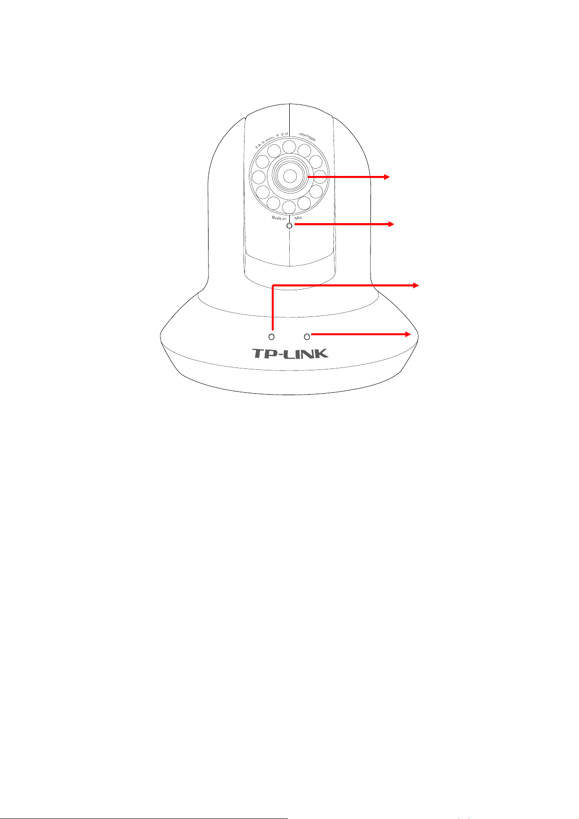
2.3.1 Front view 2.3.1 Front view
Focus Adjustment Ring
Built-in Microphone
Power LED
Ethernet LED
Focus Adjustment Ring: Adjust the focus to get a clear image.
Built-in Microphone: Built-in microphone for two-way audio.
Power LED: Power LED will light up after completing the boot process.
Ethernet LED: Ethernet LED will light up after successfully connecting to the Ethernet.
5
Page 11
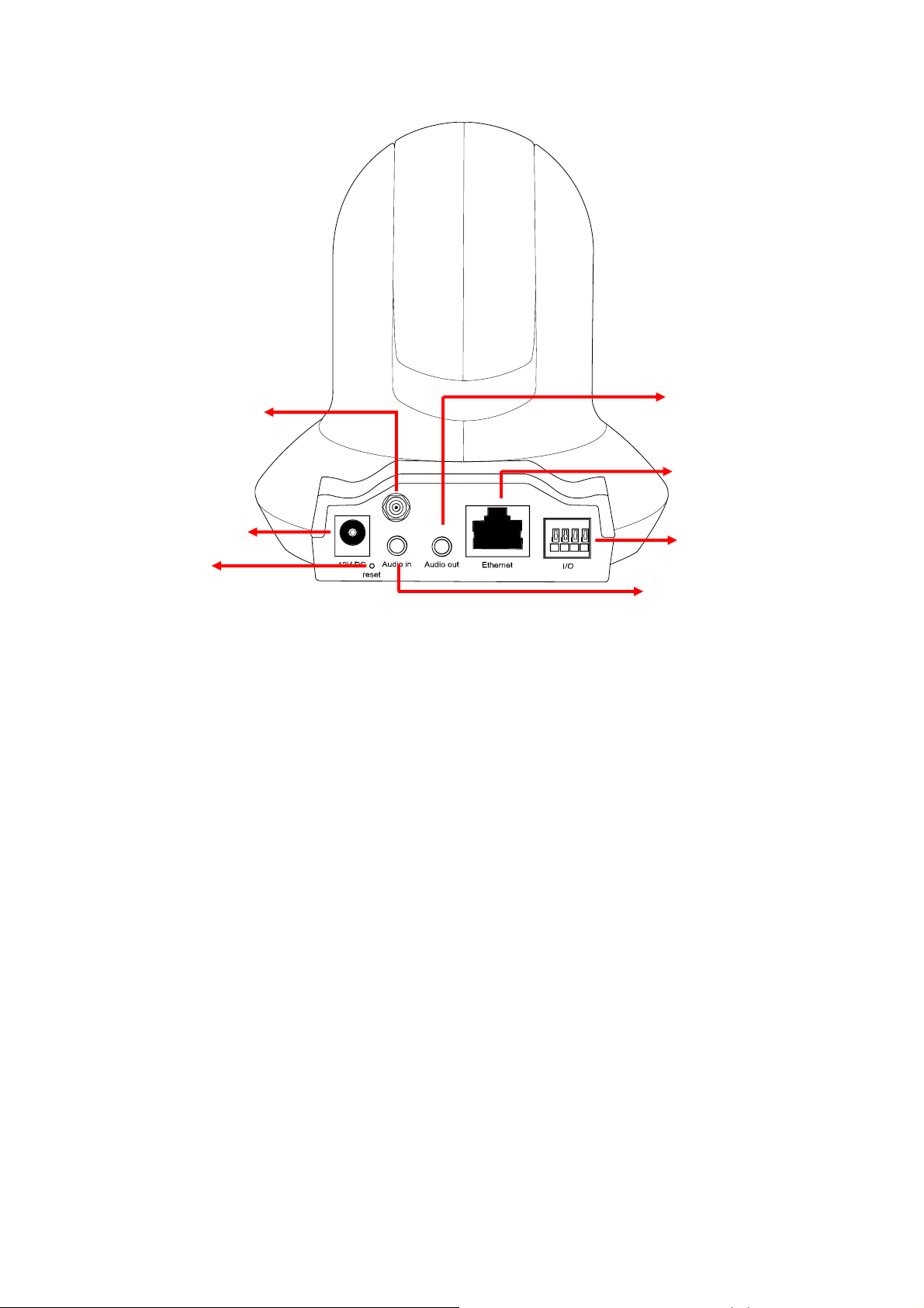
2.3.2 Rear view
Antenna Connector
Power Connector
Reset Button
Audio Out
Network Connector
General I/O
Terminal Block
Audio In
Power Connector: For connection of 12V DC input.
Reset Button: To reset the IP camera, please carry out the following steps.
z Make sure the camera is powered on for at least 30 seconds to complete its normal startup.
z Keep the camera powered on, then press and hold the Reset button for more than 10 seconds.
Afterwards release it, and the camera will be restored to factory defaults after rebooting.
Antenna Connector: For connection of IEEE 802.11b/g wireless network.
Audio In: To support audio in with Microphone for two way audio.
Audio Out: To support audio out with earphones or speakers for two way audio.
Network Connector: For connection to the Ethernet via Ethernet cable.
General I/O Terminal Block: Input/Output to support External Alarm and Sensor used for motion
detection, event triggering and alarm notification, etc.
6
Page 12

Chapter 3 Using IP Camera via Web Browser
3.1 Obtain the IP Address
1. Insert the provided CD into your CD-ROM driver. The Setup Wizard will automatically pop up on
your computer’s screen as shown in the figure below.
2. Choose the Intelligent IP Installer, and then the next screen appears. Click on Intelligent IP
Installer to begin the installation.
3. After the installation is finished, click Start > All Programs > TP-LINK > Intelligent IP Installer >
Intelligent IP Installer to start using the program.
7
Page 13
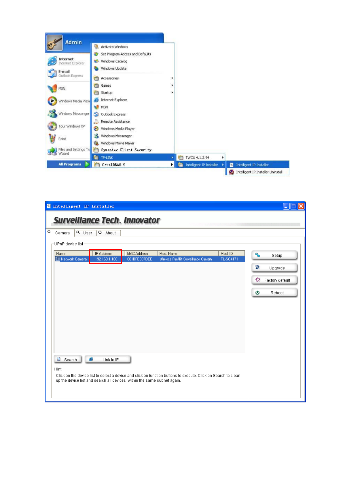
4. The following screen will then display. Click the Search button to search Network Cameras in the
network; it displays Network Cameras information including IP Address.
3.2 Windows Web Browser
1. Click Link to IE button or launch your web browser, and enter the IP address (obtain from the figure
above) of the IP camera in the Location / Address field of your browser.
8
Page 14
)
ė
)
Note:
1) For the first time login with IE, you will need to enable “Download signed ActiveX controls”.
Please go to Tool
signed ActiveX controls to prompt it. For detailed information, please refer to the Quick
Installation Guide.
Internet Options…ėSecurityėCustom Level… and find Download
2) If you only want to view the video without setting page, enter “http://<IP>/index2.htm
web URL. For example, you can enter “http://192.168.1.100/index2.htm”
view the video without setting page.
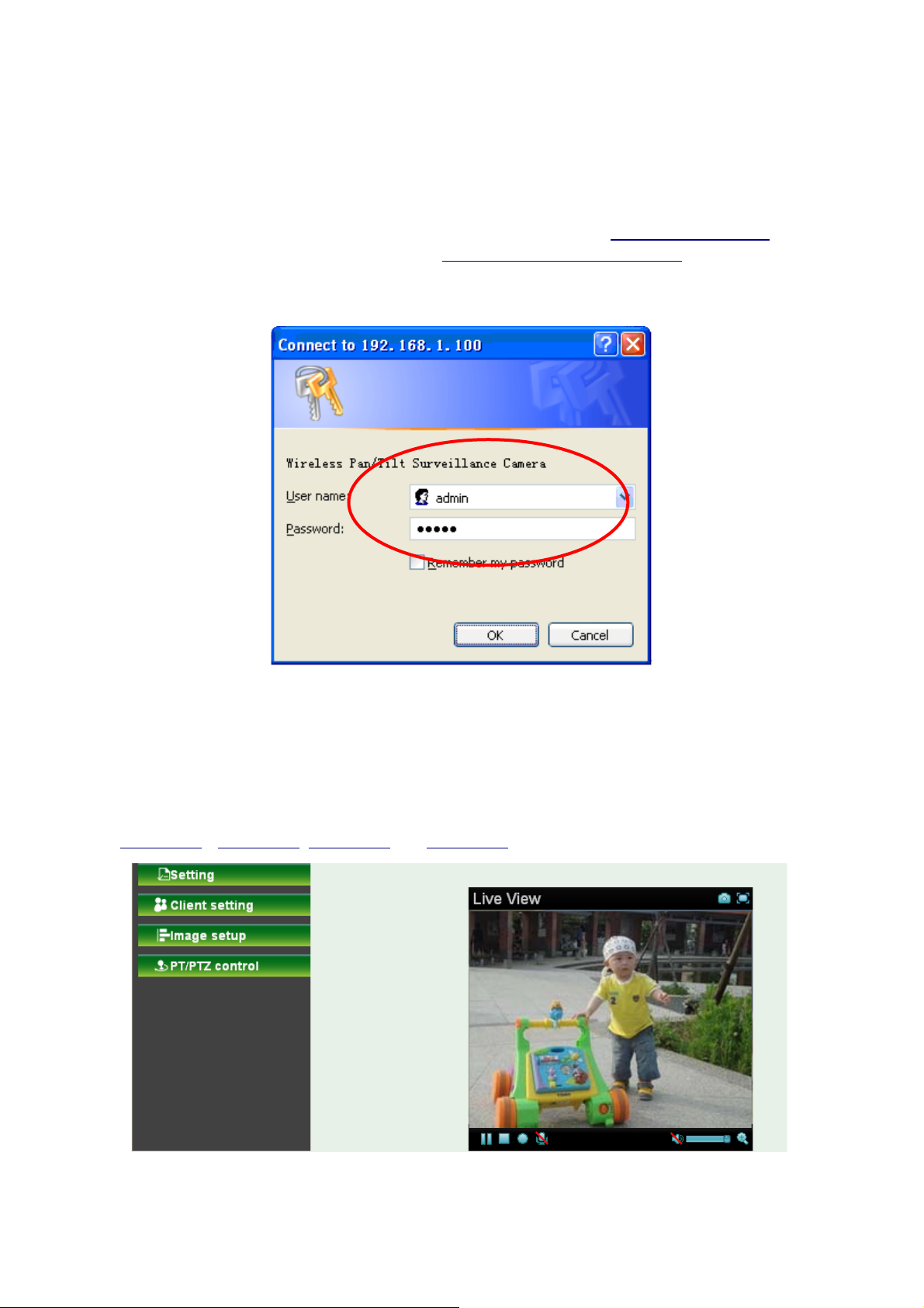
2. Enter the default User name “admin” and password “admin” in the login window as shown below.
as your web URL to
” as your
Note:
The default user name “admin” and the password “admin” are set at the factory for the administrator.
You can change them in the Account Menu (Please check “Setting Basic Security
Account”)
3. The monitor image will be displayed in your browser. In the far left side of main configuration are
Setting, Client Setting, Image Setup and PT/PTZ control. For more details, you can check
Section 6.2
ΕSection 6.3, Section 6.4 and Section 6.5.
9
Page 15

)
3.3 Mac Web Browser
1. Click the Safari icon, and enter the IP address of the IP camera in the Location / Address field of
your browser.
Note:
If you only want to view the video without setting page, enter “http://<IP>/index2.htm” as your web
URL.
10
Page 16

)
2. Enter the default User name “admin” and password “admin” in the dialog box as shown below.
Note:
The default user name “admin” and the password are set at the factory for the administrator. You
can change them in the Account Menu (Please check “Setting Basic Security Account”)
11
Page 17

3. The monitor image will be displayed in your browser. In the far left side of main configuration are
Setting, Client Setting, Image Setup and PT/PTZ control. For more details, you can check
Section 6.2
, Section 6.3, Section 6.4 and Section 6.5.
12
Page 18

)
y
Chapter 4 Using IP Camera via Mobile Phone
4.1 Mobile Phone Viewing
To use IP cameras via mobile phones, please make sure your RTSP is set to “On” (Default is “On”). To
change the settings of IP cameras, Please check “Settings Basic Camera General.”
4.1.1 3G Mobile Phone Streaming Viewing
For 3G mobile phone viewing, type “rtsp://<IP>:<PORT>/video.3gp ” into your 3G Streaming Link. <IP>
is the Public IP address of your IP camera (to obtain the IP Address, please refer to
<PORT> is the RTSP port of your IP camera (Default value is 554.) Example:
rtsp://192.168.1.100:554/video.3gp.
Note:
You can also use RTSP clients (RealPlayer, VLC, QuickTime layer etc) to view RTSP streaming, just
type in “rtsp://<IP>:<PORT>/video.3gp” as the Player URL.
4.1.2 2.5G Mobile Phone WAP Viewing
For 2.5G mobile phone viewing, type “http://<IP>/mobile.wml ” into your 2.5G WAP Browser. <IP> is the
Public IP address of your IP camera (to obtain the IP Address, please refer to Section 3.1
Section 3.1);
).
4.1.3 2.5G Mobile Phone Browser Viewing
For 2.5G mobile phone viewing, type “http://<IP>/mobile.htm ” into your 2.5G Web Browser. <IP> is the
Public IP address of your IP camera (to obtain the IP Address, please refer to Section 3.1
).
4.2 Using IP Camera via iPhone
You can use TP-LINK Web User Interface via iPhone. If you want to use TP-LINK web UI via iPhone,
please follow the setting process below.
1. Select Safari function 2. Enter IP address in
our web link.
13
Page 19

g
)
3. Type name and password.
Default value is admin /
admin. Then click Lo
in In.
4. The TP-LINK User Interface
and live image will show up in
the middle of screen.
Note: It will show continuous
snapshots, not a real time video
streaming. Therefore, the recording
feature is disabled.
14
Page 20

Chapter 5 MSN Messenger
Please follow the steps below to set up the Messenger function.
1. Application of a new MSN account: You can download MSN software freely and create a new
MSN account (e.g. camera at home@msn.com) to use Microsoft Live Messenger.
2. Login Account and Password: Go to SettingBasicNetworkMessenger, set the
Messenger to “On”. Then, enter the new account (camera at home@msn.com) and password to
login.
Note: This account (e.g. camera at home@msn.com) is not your commonly used MSN account but
a new one applied for IP Camera.
(Supports up to Windows Live Messenger version 8089)
3. IP Notification: Choose “On” at the option of IP Notification. If this feature switches On, camera will
send IP notification to the users who are allowed.
4. Privacy & User & Allow List: Choose “On” at the option of Privacy, then User column will appear
and be able to build Allow List, so that only the users listed can access the camera via MSN.
15
Page 21

5. Log in Working Account: Use your working account to login in the Messenger software. And add
the camera’s MSN account (camera at home@msn.com) as a contact.
6. Check its status. Normally it should be online.
16
Page 22

7. The Camera at home will show up with its Public IP and Private IP after sending a message of
“Ping” in the lower key (if the option of IP Notification is “On”).
8. Click the camera icon
and select View a contact’s webcam to view the video.
17
Page 23

9. The IP Camera will accept your invitation; the live video will show up in the right screen after few
seconds.
18
Page 24

10. Click Action button and choose Start Control Panel to use control panel.
11. The dialog box will show up with “This application is not part if Window Live Message…” Tick the
box of “Don’t show me this again” and click OK.
19
Page 25
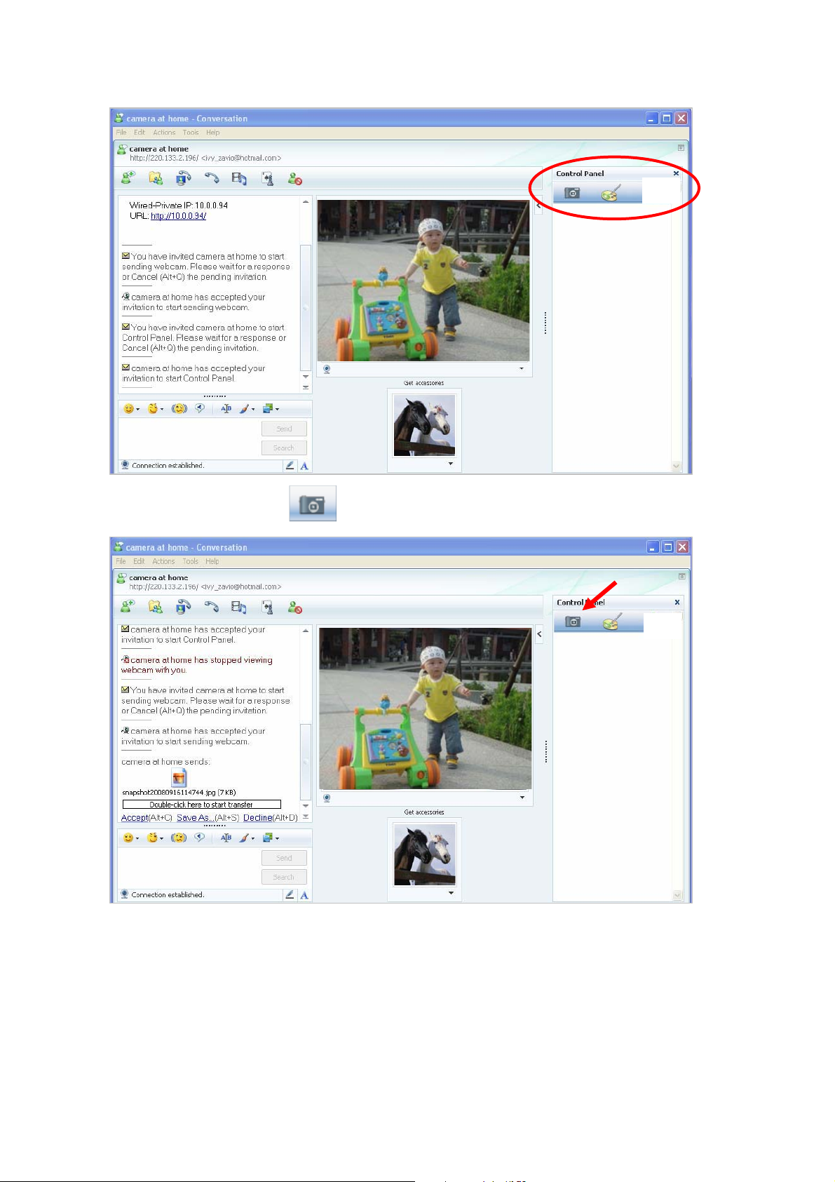
12. The IP Camera will accept your invitation to start Control Panel.
13. You can click Camera icon
to snapshot then the picture will send to you immediately.
Snapshot
20
Page 26
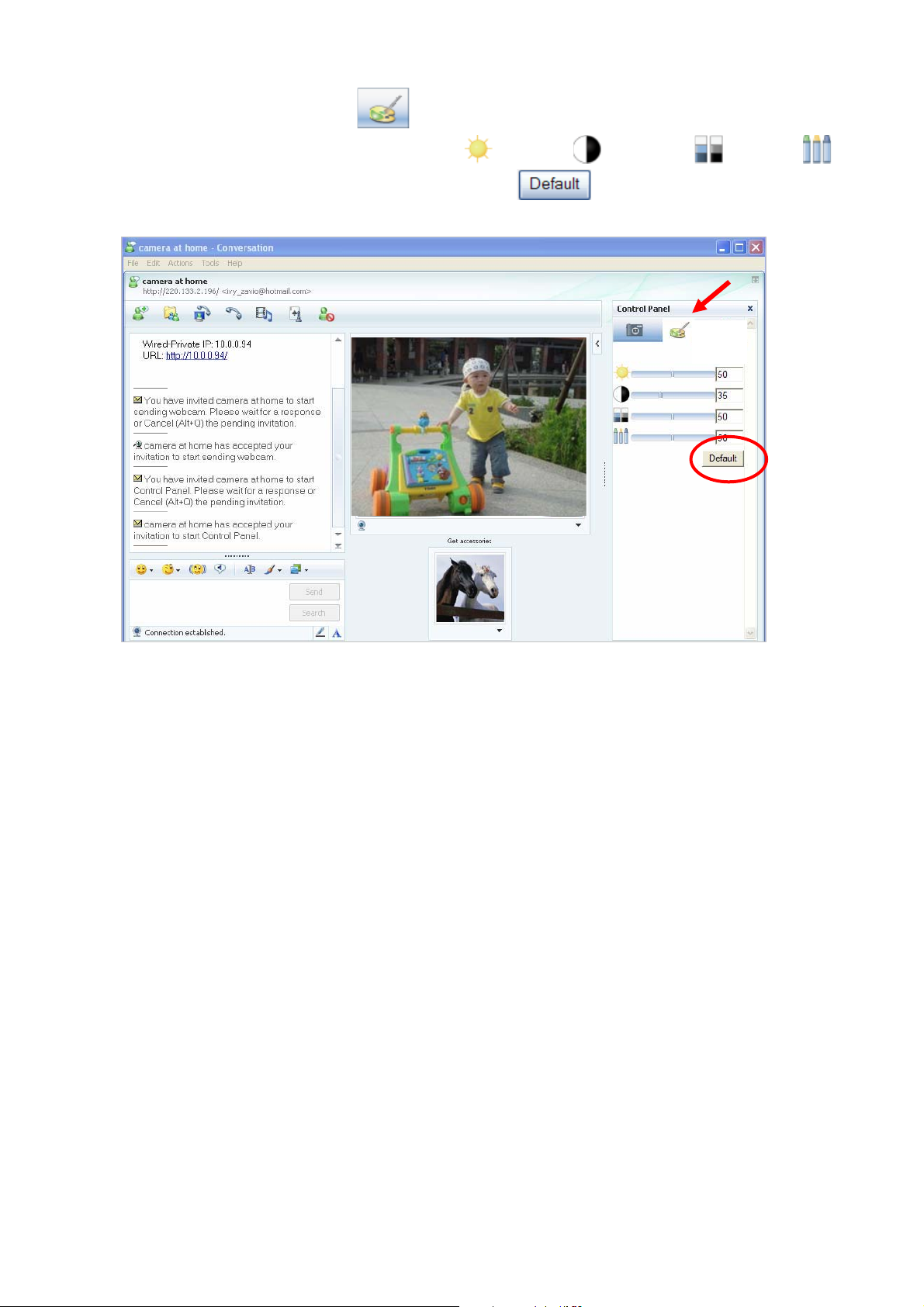
14. You can click paint palette icon showing up with tool bar to set up image. Then, you can
use the tool bar to optimize video Brightness
After the adjustment of all setting, you can still click
original setting.
, Contrast , Saturation and Hue .
to make the setting back to the
Image Setup
21
Page 27

Chapter 6 Configuration of Main Menu
In the far left side of main configuration are Setting, Client Setting, Image Setup and PT/PTZ control.
Please see the content behind for more details. In the right hand side of the below picture, you can see
the Live View screen of web user interface. There are some functions, such as Snapshot, Zoom and
Audio and Video Play.
Snapshot
Fullscreen
Video Play buttons
Audio buttons
6.1 Live View
6.1.1 Snapshot
You can capture a still image shot by the camera and save it in your computer.
Symbols Meaning
Save Save the picture in your computer
Close Return to the view page
A snapshot window will appear
Full Screen
Zoom in/out
22
Page 28

)
6.1.2 Zoom in / out the image via the monitor window
z Click
z Pull the
showed on the above window.
z You can use the left click of your mouse to move the to any where on the window.
to display the digital zoom in window.
to adjust the digital zoom range and it will be
6.1.3 Video play buttons
Symbols Meaning
Pause the current video
Play the video
Stop the current video
Record the current video
Note:
Concerning the recording storage requirement of your hard disk, please refer to the APPENDIX B.
Storage Requirement Table.
6.1.4 Audio buttons
Symbols Meaning Note
mean the speakers of your computer
Speakers turned on
are turned on to transmit the sounds
from the connected IP camera(s)
23
Page 29

Speakers turned off
Microphone turned on
Microphone turned off
Volume control bar
mean you can broadcast to the
connected IP camera(s) via the
Ethernet using your microphone
6.2 Setting
This function is only for the Administrator. Click SETTING to get into the Basic and Advanced Setting
menu. The former includes for sub-folders, such as System, Camera, Network, and Security. The
latter includes PT/PTZ control, Preset position, Patrol, FTP Client, SMTP, Http Event, Alarm output,
Schedule, Alarm input, Motion Detection, and System Log.
6.3 Client Setting
This function is only for the client.
24
Page 30

Click Client Setting to control Mode, View Size, Protocol, and Video Buffer.
6.3.1 Mode
Click the pull-down box to choose between MPEG-4 MJPEG, and JPEG video compression mode.
MJPEG streaming is unavailable if RTSP mode is “On.” (Please check Setting Basic Camera
General.)
6.3.2 View Size
Select the desired display image size to 640X480 or 320X240.
6.3.3 Protocol
Select the transferring protocol from TCP, UDP, HTTP and Multicast.
6.3.4 Video Buffer
Turn the Video Buffer function On/Off. The Video Buffer function makes the streaming more smoothly in
unsteady network environment, but might cause a little delay in live viewing.
6.4 Image Setup
You can use the tool bar to optimize video Brightness, Contrast, Saturation and Hue.
6.4.1 Brightness
The higher value the brightness is, the brighter the image is.
6.4.2 Contrast
The contrast is a measure of a display system, defined as the ratio of white to black that the system is
capable of producing. The higher value the contrast is, the more delicate of color you can have.
6.4.3 Saturation
The saturation of a color is determined by a combination of light intensity and how much it is distributed
across the spectrum of different wavelengths. The higher value the saturation is, the more colorful the
image will be.
6.4.4 Hue
Hue is one of the three main attributes of perceived color, affected by different wavelength of color. With
higher value of hue, color will be much more vivid.
25
Page 31

6.4.5 Default
After the adjustment of all setting, you can still click Default to make the setting back to the original
setting.
6.5 PT/PTZ Control
6.5.1 Pan / Tilt / Home control buttons
If you want the IP camera to move, please click the arrow button of the corresponding direction. When
you click
yourself. For more detailed information, please refer to
button, the camera will return to “home position”—a preset position which can be set by
Section 8.2.
6.5.2 Other camera control functions
¾ Preset:
z Set: Click Set button to save the current position of the camera as a preset position.
z Go: Click Go button and choose one of the preset positions, then the camera will move to the
preset position.
¾ Patrol:
z Set: Click Set button and choose one of the patrol tours, then the chosen tour will be set as
default.
z Go: Click Go button, then the camera will move along the default tour path.
26
Page 32

)
Note:
Before you start this function, you need to specify Guard tour setting in Setting Advance Patrol.
For more detailed information about Patrol functions, please refer to Section 8.3
.
27
Page 33

Chapter 7 Setting-Basic
Click the folder of Basic to display the sub folders including System, Camera, Network, and Security.
7.1 System
Click the folder of System to display the sub-folders including Information, Date/Time, and Initialize.
7.1.1 Information
The Information page provides the product factory information which includes Product Name,
Firmware Version and Web Version.
28
Page 34

)
7.1.2 Date/Time
The Date/ Time page displays all options of time setting.
¾ Current date / time: This displays the current date and time of this IP Camera.
¾ PC clock: This displays the date and time of the monitoring PC clock.
¾ Date / Time format: You can click the pull down box to select different time display formats.
¾ Adjust: You can select one of those four adjusting modes for your IP Camera.
z Keep current setting: Select this mode to keep the current date and time of this IP Camera.
z Synchronize with PC: Select this mode to keep the date and time of this IP Camera is the
same as the monitoring PC.
z Manual setting: Select this mode to adjust manually the date and time of this IP Camera.
z Synchronize with NTP: Specify the NTP server name and the Refresh Interval to synchronize
the date and time of this IP Camera with those of the time server, known as the NTP server.
¾ Time Zone: You can select the Time Zone of the format from Greenwich Mean Time. The time will
display the same as the current date / time option.
¾ Daylight Saving Time: There are two modes to choose for setting up daylight saving time.
z By Date: Set the start and end time by select month, day, hour, and minute.
z By Week Number: Set the start and end time by select month, week, hour, and minute.
Note:
The NTP server (Network Time Protocol) is the time server which is an Internet standard protocol built on
the top of TCP/IP. This assures accurate synchronization to the millisecond of computer clock times in a
network of computers.
29
Page 35

)
)
7.1.3 Initialize
¾ Reboot: Click this button to reboot. A confirmation dialogue will appear and then click “OK” to
process. It takes two minutes to reboot this IP Camera.
¾ Factory Default: Click this button to reset this IP Camera to the factory default setting. A
confirmation dialogue will appear and then click “OK” to process. Don't turn off this IP Camera until
the device reboots.
¾ Backup Setting data: You can save the setting data of this IP Camera into a file. Click “Save” and
follow the instructions on the browser to save the setting data file to your specified location.
¾ Restore Setting: Download the saved setting data of this IP Camera. Click “Browse” and select
saved file. Click “OK” and this IP Camera is adjusted according to the loaded data; the camera will
restart.
¾ Firmware Update: Upgrade the device software. Click “Browse” and select the file for upgrading. A
confirmation dialogue will appear. Click “OK” to start upgrading. This IP Camera will reboot upon
completion.
Note:
Note:
Use only upgrade files that are special for this IP Camera. Otherwise problems may occur. Don't
turn off the IP Camera power or disconnect the network until the upgrading is completed.
After upgrading new firmware, please execute “Factory Default” first to make it work.
¾ Upload Language Pack: Upgrade the device language pack. Click “Browse” and select the file for
upgrading. A confirmation dialogue will appear. Click “OK” to start upgrading. The upgrade is applied
immediately. The default language is “English”.
30
Page 36

)
7.2 Camera
Click the folder of Camera to display the sub folders including General, MPEG4 and MJPEG.
7.2.1 General
¾ RTSP: Switch RTSP “On” or “Off.” When the RTSP mode is “On”, MJPEG streaming is unavailable.
z RTSP Port: Specify the transmission port number of RTSP streaming. The default value is 554.
z Port Range: Specify the transmission port range of RTP streaming video. RTP will select a port
randomly from this range.
Note:
RTSP (Real Time Streaming Protocol) is a protocol for use in streaming media system which allows
clients to remotely control a streaming video server. RTSP is supports by most of the media clients such
as Real Player, QuickTime and VLC etc.
31
Page 37

)
¾ Image Rotate: Select the screen display “flip”, “mirror”, or “flip + mirror.”
¾ Audio Codec: If this option is selected “On”, the microphone will start sound reception.
¾ Exposure mode: You can choose 50Hz, 60Hz or Auto. If you choose Auto option, the camera will
adjust automatically to perform well.
¾ White Balance: You can choose the white balance to Auto, Florescent, Incandescent and Black &
White.
¾ IR: You can turn IR light On/Off or Auto. If you select Auto mode, you can adjust threshold for IR
Auto-On and Auto-Off respectively. In the right hand side of threshold bar, if the tool bar is closer to
the right, the IR will auto-on easily in the dark environment. Conversely, in the left hand side of
threshold bar, if the tool bar is more approached to the left, the IR will auto-off easily in the bright
environment.
Note:
1. The effective range of the IR (Infrared) light is 10 meters (33 feet), and it is strongly suggested that
2. Normally, 10 seconds after the environment becomes darker than the threshold, the camera will
you install it in a place without any barriers within 3 meters of the field of view (10 feet). Reflected
light from a large closed barrier (such as a wall) may cause the camera to shut down the infrared
light.
turn on the IR (Infrared) light. One typical abnormal situation is that a barrier is very close to the
camera and shields all available light.
¾ Overlay:
z Text Overlay: You can see some information on the display screen which includes Text color,
Background color, Alias, Date/Time and Display position.
32
Page 38

z Privacy Mask: You can cover a specific area of the video image with the black bar. The black
bar can be moved.
7.2.2 MPEG-4
A. Computer View
If RTSP is On (please check “Setting Basic Camera General”), the option of Viewer
Authentication and Multicast Streaming will appear.
33
Page 39

)
¾ Viewer Authentication: If the viewer authentication is On, the users will be requested to key in
username and password when viewing through RTS
¾ Multicast Streaming (If it’s on):
P.
z Multicast Address: Specify the multicast server address.
z Video / Audio Port: Specify th
number from 1024 to 65535.
z Time-to-Live: Set the maximum TTL that multicast can pass through. Specify the value from 1
to 255.
¾ Image Size: Specify the image size when the network camera transmits. You can choose among
640 x 480, 32
¾ Frame Rate: Set the frame rate of the MPEG4 image. You can choose values from 1, 2, 3, 4, 5, 7,
10, 15, 20, 25, and 30 fps. The unit “fps
¾ Quality:
z Auto: The quality and bitrate will be adjusted automatically according
z Fixed
and Excellent.
z Fixed Bitrate: Set the bitrate of MPEG4 image transmission for a line. You can select the value
from 64, 128, 25
Note:
0 x 240, and 160 x 120.
Quality: You can select the value of quality among Medium, Standard, Good, Detailed
6, 384, 512, 768, 1024, 1280, 1536, and 2048 kbps.
e transmission port number of the video data. Specify an even
” stands for “frames per second”.
to the frame rate.
Concerning how to select the suit
APPENDIX
B. Mobile View
A. Frame-rate & Bitrate Table
able image quality for Fixed Quality or Fixed Bitrate, please refer to the
.
If RTSP is On (please check “Setting Basic Camera General”.), the option of Viewer
Authentication and Multicast Streaming will appear.
34
Page 40

)
)
Note:
If RTSP is
¾
¾ Multicast Streaming (If it’s on):
¾ Image Size: The image size of Mobile View is fixed at 320x240 or 160 x 120.
¾ Frame Rate:
¾ Quality:
off, Mobile View will be disabled.
Viewer Authentication: If the viewer authentication is On, the users will be requested to key-in
username and password when viewing t
z Multicast Address: Specify the multicast server address.
z Video / Audio Port: Specify th
number from 1024 to 65535.
z Time-To-Live: Set the maximum TTL that multicast can pass through. Specify the value from 1
to 255.
Set the frame rate of the MPEG4 image. You can choose values from 5 and 10fps.
The unit “fps” stands for “frames sent per second”.
z Auto: The quality and bitrate will be adjusted a
z Fixed
and Excellent.
z Fixed Bitrate: Set the bitrate of MPEG4 image transmission for a line. You can select the value
from 16, 32, 48,
Quality: You can select the value of quality among Medium, Standard, Good, Detailed
64, 128, and 256 kbps.
hrough RTSP.
e transmission port number of the video data. Specify an even
utomatically according to the frame rate.
Note:
Concerning how to select the suit
APPENDIX
A. Frame-rate and Bitrate Table
7.2.3 MJPEG
able image quality for Fixed Quality or Fixed Bitrate, please refer to the
.
If RTSP is Off (please check “Setting Basic Camera General”.), the option of Image Size,
Frame rate and Quality will appear.
35
 Loading...