

TP-Link JetStream T1500-28TC, JetStream T1500-28PCT, JetStream T1500G-10MPS Installation Manual

Business Networking Solution
Installation Guide
JetStream Smart Switch
T1500-28TC/T1500-28PCT

About this Installation Guide
This Installation Guide describes the hardware characteristics, installation methods and the
points that should be attended to during the installation. This Installation Guide is structured as
follows:
Chapter 1 Introduction
This chapter describes the external components of the switch.
Chapter 2 Installation
This chapter illustrates how to install the switch.
Chapter 3 Lightning Protection
This chapter illustrates how to prevent lightning damage.
Chapter 4 Connection
This chapter illustrates how to do the physical connection of the switch.
Appendix A Troubleshooting
Appendix B Specifications
Audience
This Installation Guide is for:
Network Engineer Network Administrator
Conventions
• Some models featured in this guide may be unavailable in your country or region. For local
sales information, visit http://www.tp-link.com.
• The figures in Chapter 2 to Chapter 4 are for demonstration purposes only. Your switch may
differ in appearance from that depicted.
• This guide uses the specific formats to highlight special messages. The following table lists
the notice icons that are used throughout this guide.
Remind to be careful. A caution indicates a potential which may result in device damage.
Remind to take notice. The note contains the helpful information for a better use of the
product.
Related Document
This Installation Guide is also available in PDF on our website. To obtain the latest
documentation and product information, please visit the official website:
http://www.tp-link.com

Contents
Chapter 1 Introduction ——————————— 01
1.1 Product Overview ...........................................................01
1.2 Appearance .......................................................................01
Chapter 2 Installation ——————————— 06
2.1 Package Contents ..........................................................06
2.2 Safety Precautions .........................................................06
2.3 Installation Tools ..............................................................08
2.4 Product Installation ........................................................09
Chapter 3 Lightning Protection ——————— 11
3.1 Cabling Reasonably........................................................11
3.2 Connect to Ground .........................................................13
Chapter 4 Connection ——————————— 17
4.1 Ethernet Port ....................................................................17
4.2 Verify Installation .............................................................17
4.3 Power On ............................................................................17
4.4 Initialization ........................................................................18
Chapter 5 Login to the Switch ———————— 19
5.1 ConguretheSwitchviaGUI ......................................19
5.2 ConguretheSwitchviaCLI .......................................20
Appendix A Troubleshooting ———————— 21
AppendixBSpecications ————————— 22

01
JetStream Smart Switch
Introduction
Chapter 1 Introduction
1.1 Product Overview
T1500-28TC/T1500-28PCT is compliant with the IEEE802.3 Ethernet protocols.
T1500-28TC/T1500-28PCT is equipped with powerful management interface, via
which system, port, network, VLAN and priority can be configured. They provide a
variety of service features and multiple powerful functions with high security. The
EIA-standardized framework and smart configuration capacity can provide flexible
solutions for a variable scale of networks. QoS and IGMP snooping/filtering optimize
voice and video application. SNMP, RMON, WEB Log-in bring abundant management
policies.
T1500-28TC/T1500-28PCT integrates multiple functions with excellent performance,
and are friendly to manage, which can fully meet the need of the users demanding
higher networking performance.
T1500-28PCT Switch is also a Power Sourcing Equipment (PSE*). All the fast Ethernet
RJ45 ports on the switch support Power over Ethernet (PoE*) function, which can
automatically detect and supply power with those powered devices (PDs*) complying
with IEEE 802.3af and IEEE 802.3at.
*PSE: a device (switch or hub for instance) that provides power through an Ethernet
cable.
*PoE: This technology describes a system to transmit electrical power, along with data,
to remote devices over standard twisted-pair cable in an Ethernet.
*PD: a device powered by a PSE and thus consumes energy. Examples include powering
network cameras, wireless LAN access points, IP telephones, network hubs, embedded
computers etc.
1.2 Appearance
■
Front Panel
The front panel of T1500-28TC is shown as the following figure.
Figure 1-1 Front Panel of T1500-28TC
ResetLEDs 10/100Mbps RJ45 Port 10/100/1000Mbps RJ45 Port
SFP Port

02
JetStream
Smart Switch
Introduction
LEDs
LED Status Indication
PWR
On The switch is powered on
Off The switch is powered off or power supply is abnormal
Flashing Power supply is abnormal
SYS
Flashing The switch works properly
On/Off The switch works improperly
10/10 0M
On
A device is connected to the corresponding port but no
activity
Flashing Data is being transmitted or received
Off No device is connected to the corresponding port
1000M
Green
On
A 1000Mbps device is connected to the corresponding
port, but no activity
Flashing Data is being transmitted or received
Yellow
On
A 10/100Mbps device is connected to the corresponding
port, but no activity
Flashing Data is being transmitted or received
Off No device is connected to the corresponding port
Reset
With the switch powered on, press Reset button for 5 seconds to reset the software
setting to its factory default settings.
10/100Mbps RJ45 Port
Designed to connect to the device with a bandwidth of 10Mbps or 100Mbps. Each
has a corresponding 10/100M or PoE LED.
10/100/1000Mbps RJ45 Port
Designed to connect to the device with a bandwidth of 10Mbps, 100Mbps or
1000Mbps. Each has a corresponding 1000M LED.
SFP Port
Designed to install the SFP module. T1500-28TC features some SFP transceiver
slots that are shared with the associated RJ45 ports. The associated two ports
are referred as a "Combo" port, which means they cannot be used simultaneously,
otherwise only SFP port works. Meanwhile, the associated two ports share the same
LED. For T1500-28TC, Port 27 shares the same LED with Port 27F and Port 28 shares
the same LED with Port 28F.

03
JetStream Smart Switch
Introduction
The front panel of T1500-28PCT is shown as the following figure.
Figure 1-2 Front Panel of T1500-28PCT
LEDs
10/100Mbps RJ45
Port and PoE Port
10/100/1000Mbps
RJ45 Port
LED Mode
Switch Button
SFP Port
Reset
LEDs
T1500-28PCT has an LED mode switch button which is for switching the LED
status indication. When the Speed LED is on, the port LED is indicating the data
transmission status. When the PoE LED is on, the port LED is indicating the power
supply status. By default, the Speed LED is on. Pressing the mode switch button, the
Speed LED will turn off and the PoE LED will light up. Then the PoE LED will turn off
after being on for 60 seconds and the Speed LED will light up again.
When the Speed LED is on, the port LED is indicating the data transmission status.
LED Status Indication
PWR
On The switch is powered on
Off The switch is powered off or power supply is abnormal
Flashing Power supply is abnormal
SYS
Flashing The switch works properly
On/Off The switch works improperly
FAN
Green All the fans work properly
Yellow Not all the fans work properly
PoE Max
On The remaining PoE power≤7W
Flashing
The remaining PoE power keeps ≤7W after this LED is
on for 2 minutes
Off The remaining PoE power>7W
10/10 0M
or PoE
Green
On
A 100Mbps device is connected to the corresponding
port, but no activity
Flashing Data is being transmitted or received
Yellow
On
A 10Mbps device is connected to the corresponding
port, but no activity
Flashing Data is being transmitted or received
Off No device is connected to the corresponding port

04
JetStream
Smart Switch
Introduction
1000M
Green
On
A 1000Mbps device is connected to the corresponding
port, but no activity
Flashing Data is being transmitted or received
Yellow
On
A 10/100Mbps device is connected to the corresponding
port, but no activity
Flashing Data is being transmitted or received
Off No device is connected to the corresponding port
When the PoE LED is on, the port LED is indicating the power supply status.
LED Status Indication
PWR
On The switch is powered on
Off The switch is powered off or power supply is abnormal
Flashing Power supply is abnormal
SYS
Flashing The switch works properly
On/Off The switch works improperly
FAN
Green All the fans work properly
Yellow Not all the fans work properly
PoE Max
On The remaining PoE power≤7W
Flashing
The remaining PoE power keeps ≤7W after this LED is
on for 2 minutes
Off The remaining PoE power>7W
10/10 0M
or PoE
Green
On The port is supplying power normally
Flashing
The supply power exceeds the correponding port's
maximum power
Yellow
On Overload or short circuit is detected
Flashing Power-on self-test has failed
Off No PoE power supply is provided on the port
1000M
Green
On
A 1000Mbps device is connected to the corresponding
port, but no activity
Flashing Data is being transmitted or received
Yellow
On
A 10/100Mbps device is connected to the corresponding
port, but no activity
Flashing Data is being transmitted or received
Off No device is connected to the corresponding port
Reset
With the switch powered on, press Reset button for 5 seconds to reset the software
setting to its factory default settings.
10/100Mbps RJ45 Port
Designed to connect to the device with a bandwidth of 10Mbps or 100Mbps. Each
has a corresponding 10/100M or PoE LED.
05
JetStream Smart Switch
Introduction
10/100/1000Mbps RJ45 Port
Designed to connect to the device with a bandwidth of 10Mbps, 100Mbps or
1000Mbps. Each has a corresponding 1000M LED.
SFP Port
Designed to install the SFP module. T1500-28PCT features some SFP transceiver
slots that are shared with the associated RJ45 ports. The associated two ports
are referred as a "Combo" port, which means they cannot be used simultaneously,
otherwise only SFP port works. Meanwhile, the associated two ports share the same
LED. For T1500-28PCT, Port 27 shares the same LED with Port 27F and Port 28
shares the same LED with Port 28F.
■
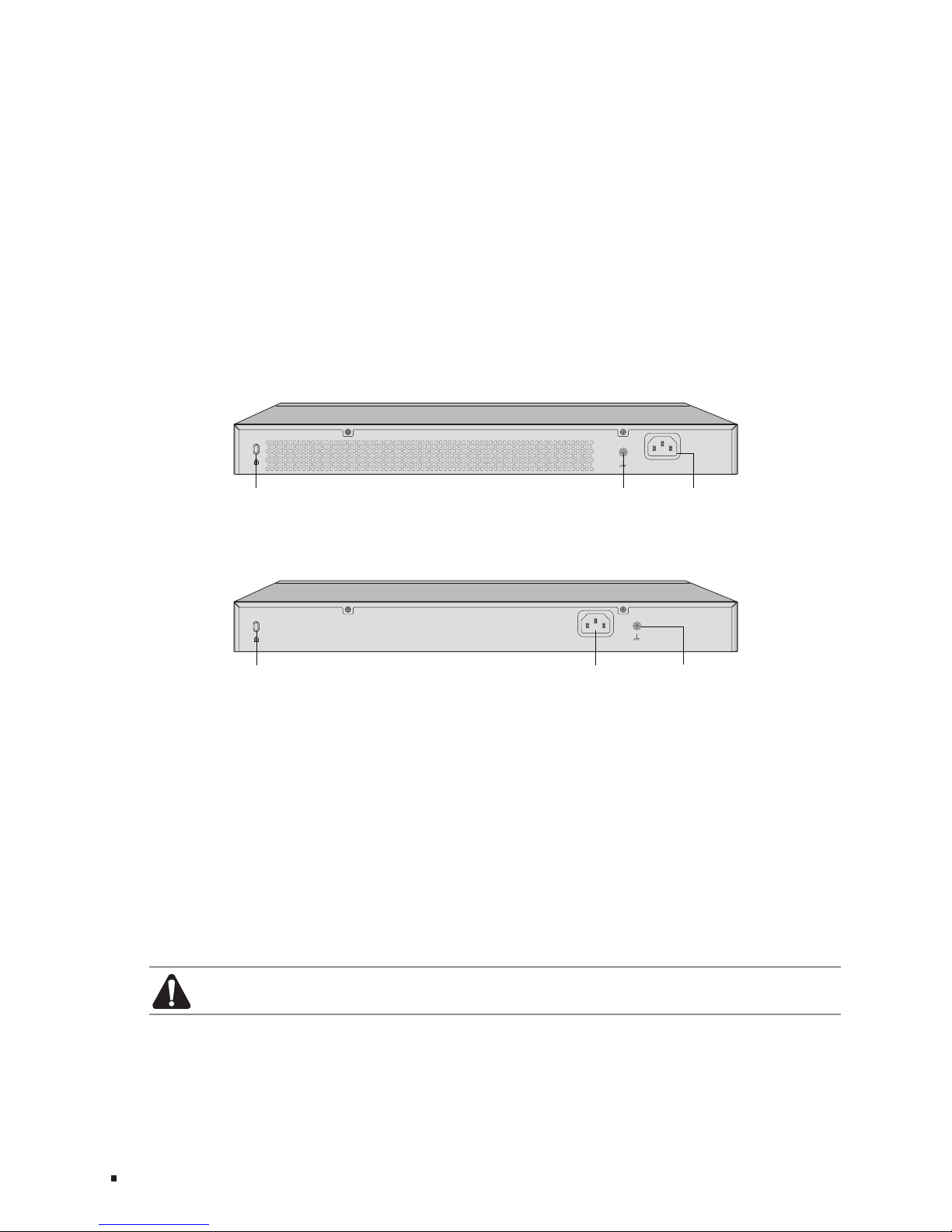
Rear Panel
The rear panel of T1500-28TC is shown as the following figure.
Figure 1-3 Rear Panel of T1500-28TC
100-240V~ 50/60Hz 0.3A
K
ensington Security Slot Grounding Terminal Power Socket
The rear panel of T1500-28PCT is shown as the following figure.
Figure 1-4 Rear Panel of T1500-28PCT
100-240V~ 50/60Hz 3.0A
K
ensington Security Slot
Grounding Terminal Power Socket
Kensington Security Slot
Secure the lock (not provided) into the security slot to prevent the device from being
stolen.
Power Socket
Connect the female connector of the power cord here, and the male connector to
the AC (Alternating Current) power outlet. Please make sure the voltage of the power
supply meets the requirement of the input voltage.
Grounding Terminal
The switch already comes with lightning protection mechanism. You can also ground
the switch through the PE (Protecting Earth) cable of AC cord or with Ground Cable.
For detailed information, please refer to Chapter 3 Lightning Protection.
Caution: Please use the provided power cord.
06
JetStream
Smart Switch
Installation
Chapter 2 Installation
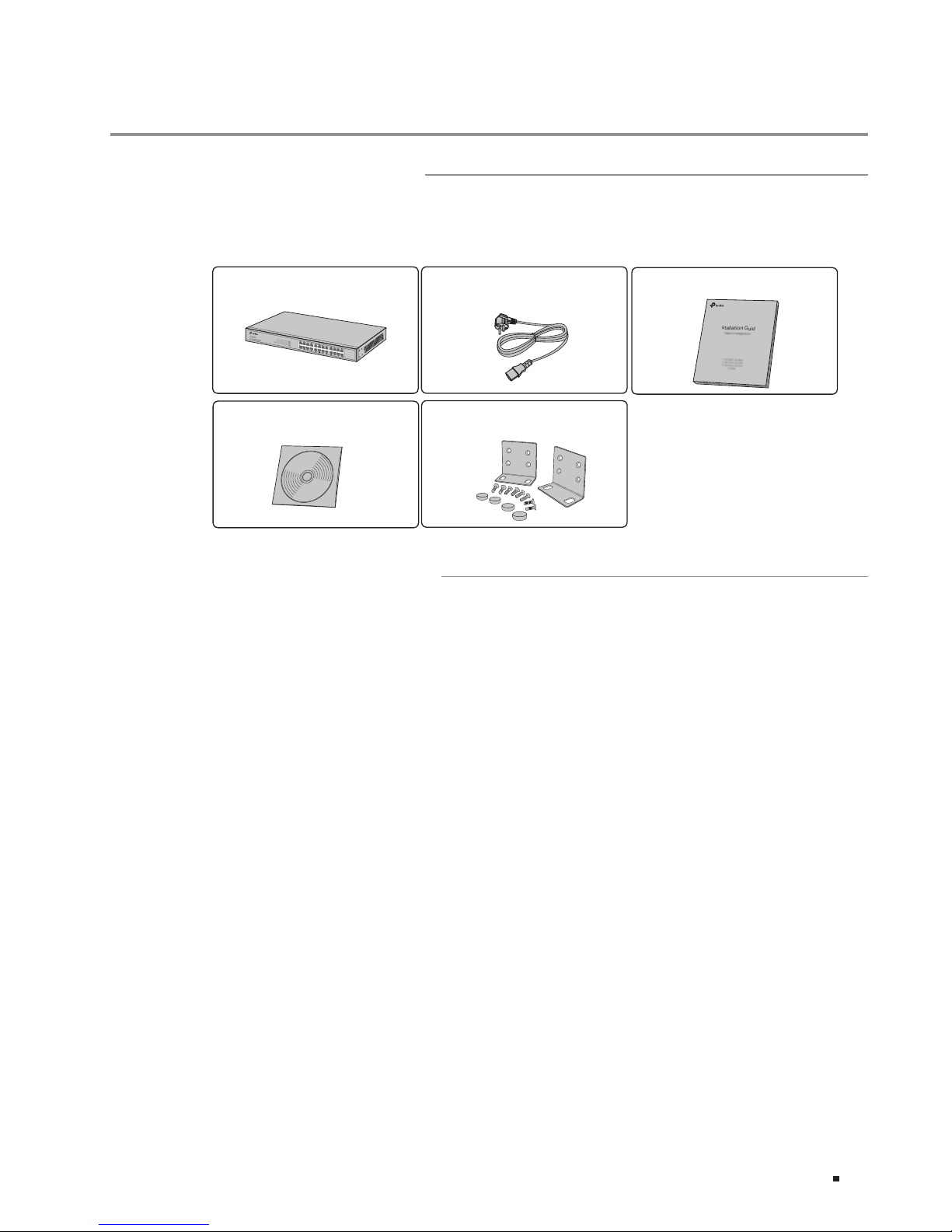
2.1 Package Contents
Make sure that the package contains the following items. If any of the listed items is
damaged or missing, please contact your distributor.
One Power Cord
One Switch
This Installation Guide
Installation Guide
Business Networking Solution
Two mounting brackets and
thettings
2.2 Safety Precautions
To avoid any device damage and bodily injury caused by improper use, please observe
the following rules.
■
Safety Precautions
■
Keep the power off during the installation.
■
Wear an ESD-preventive wrist strap, and make sure that the wrist strap has a good skin
contact and is well grounded.
■
Useonlythepowercordprovidedwiththeswitch.
■
Make sure that the supply voltage matches the specifications indicated on the rear
panel of the switch.
■
Ensure the vent hole is well ventilated and unblocked.
■
Do not open or remove the cover of the switch.
■
Before cleaning the device, cut off the power supply. Do not clean it by the waterish
cloth, and never use any other liquid cleaning method.
■
Site Requirements
To ensure normal operation and long service life of the device, please install it in an
environment that meets the requirements described in the following subsection.
One Resource CD
 Loading...