

Page 1

User Guide
AC2100 Wireless MU-MIMO VDSL/ADSL
Telephony Modem Router
Archer VR2100v
© 2021 TP-Link
1910013057 REV1.0.1
Page 2

Contents
About This Guide .........................................................................................................1
Chapter 1. Get to Know Your Modem Router. . . . . . . . . . . . . . . . . . . . . . . . . .3
1. 1. Product Overview. . . . . . . . . . . . . . . . . . . . . . . . . . . . . . . . . . . . . . . . . . . . . . . . . . . . . . . . . . . . 4
1. 2. Physical Appearance . . . . . . . . . . . . . . . . . . . . . . . . . . . . . . . . . . . . . . . . . . . . . . . . . . . . . . . . 4
1. 2. 1. Top Panel . . . . . . . . . . . . . . . . . . . . . . . . . . . . . . . . . . . . . . . . . . . . . . . . . . . . . . . . . . 4
1. 2. 2. Back Panel. . . . . . . . . . . . . . . . . . . . . . . . . . . . . . . . . . . . . . . . . . . . . . . . . . . . . . . . . 6
1. 2. 3. Side Panel . . . . . . . . . . . . . . . . . . . . . . . . . . . . . . . . . . . . . . . . . . . . . . . . . . . . . . . . . 7
Chapter 2. Connect the Hardware . . . . . . . . . . . . . . . . . . . . . . . . . . . . . . . . . . . .8
2. 1. Position Your Modem Router . . . . . . . . . . . . . . . . . . . . . . . . . . . . . . . . . . . . . . . . . . . . . . . . . 9
2. 2. Connect Your Modem Router . . . . . . . . . . . . . . . . . . . . . . . . . . . . . . . . . . . . . . . . . . . . . . . 10
Chapter 3. Log In to Your Modem Router . . . . . . . . . . . . . . . . . . . . . . . . . . . 12
Chapter 4. Set Up Internet Connections . . . . . . . . . . . . . . . . . . . . . . . . . . . . 14
4. 1. Use Quick Setup Wizard . . . . . . . . . . . . . . . . . . . . . . . . . . . . . . . . . . . . . . . . . . . . . . . . . . . . 15
4. 2. Manually Set Up an Internet Connection . . . . . . . . . . . . . . . . . . . . . . . . . . . . . . . . . . . . 15
4. 3. Test Internet Connectivity . . . . . . . . . . . . . . . . . . . . . . . . . . . . . . . . . . . . . . . . . . . . . . . . . . 16
4. 4. Set Up an IPv6 Connection . . . . . . . . . . . . . . . . . . . . . . . . . . . . . . . . . . . . . . . . . . . . . . . . . 17
4. 5. More Operation Modes . . . . . . . . . . . . . . . . . . . . . . . . . . . . . . . . . . . . . . . . . . . . . . . . . . . . . 18
4. 5. 1. Wireless Router Mode . . . . . . . . . . . . . . . . . . . . . . . . . . . . . . . . . . . . . . . . . . . . 18
4. 5. 2. 3G/4G Router Mode. . . . . . . . . . . . . . . . . . . . . . . . . . . . . . . . . . . . . . . . . . . . . . . 19
Chapter 5. TP-Link Cloud Service . . . . . . . . . . . . . . . . . . . . . . . . . . . . . . . . . . 20
5. 1. Register a TP-Link ID. . . . . . . . . . . . . . . . . . . . . . . . . . . . . . . . . . . . . . . . . . . . . . . . . . . . . . . . 21
5. 2. Change Your TP-Link ID Information. . . . . . . . . . . . . . . . . . . . . . . . . . . . . . . . . . . . . . . . . 21
5. 3. Manage the User TP-Link IDs . . . . . . . . . . . . . . . . . . . . . . . . . . . . . . . . . . . . . . . . . . . . . . . 22
5. 3. 1. Add an TP-Link ID to Manage the Router . . . . . . . . . . . . . . . . . . . . . . . . . . 23
5. 3. 2. Remove TP-Link ID(s) From Managing the Router . . . . . . . . . . . . . . . . . . 23
5. 4. Manage the Router via TP-Link Tether App . . . . . . . . . . . . . . . . . . . . . . . . . . . . . . . . . . 24
Chapter 6. Telephony . . . . . . . . . . . . . . . . . . . . . . . . . . . . . . . . . . . . . . . . . . . . . . 25
6. 1. Connecting the Telephone . . . . . . . . . . . . . . . . . . . . . . . . . . . . . . . . . . . . . . . . . . . . . . . . . . 26
6. 2. DECT . . . . . . . . . . . . . . . . . . . . . . . . . . . . . . . . . . . . . . . . . . . . . . . . . . . . . . . . . . . . . . . . . . . . . . . 26
6. 2. 1. Registering DECT Handset. . . . . . . . . . . . . . . . . . . . . . . . . . . . . . . . . . . . . . . . 26
Page 3

6. 2. 2. Configuring DECT Settings . . . . . . . . . . . . . . . . . . . . . . . . . . . . . . . . . . . . . . . 27
6. 3. Entering Telephone Information . . . . . . . . . . . . . . . . . . . . . . . . . . . . . . . . . . . . . . . . . . . . . 28
6. 4. Telephone Book . . . . . . . . . . . . . . . . . . . . . . . . . . . . . . . . . . . . . . . . . . . . . . . . . . . . . . . . . . . . 31
6. 4. 1. Telephone Book . . . . . . . . . . . . . . . . . . . . . . . . . . . . . . . . . . . . . . . . . . . . . . . . . . 31
6. 4. 2. Emergency Calls. . . . . . . . . . . . . . . . . . . . . . . . . . . . . . . . . . . . . . . . . . . . . . . . . . 32
6. 5. Telephony Devices Management. . . . . . . . . . . . . . . . . . . . . . . . . . . . . . . . . . . . . . . . . . . . 33
6. 6. Call Log . . . . . . . . . . . . . . . . . . . . . . . . . . . . . . . . . . . . . . . . . . . . . . . . . . . . . . . . . . . . . . . . . . . . 35
6. 7. Calling via Which Number . . . . . . . . . . . . . . . . . . . . . . . . . . . . . . . . . . . . . . . . . . . . . . . . . . . 35
6. 8. Call Blocks. . . . . . . . . . . . . . . . . . . . . . . . . . . . . . . . . . . . . . . . . . . . . . . . . . . . . . . . . . . . . . . . . . 36
6. 8. 1. Do Not Disturb. . . . . . . . . . . . . . . . . . . . . . . . . . . . . . . . . . . . . . . . . . . . . . . . . . . . 36
6. 8. 2. Blocking Certain Calls . . . . . . . . . . . . . . . . . . . . . . . . . . . . . . . . . . . . . . . . . . . . 37
6. 8. 3. Prevent from Dialing . . . . . . . . . . . . . . . . . . . . . . . . . . . . . . . . . . . . . . . . . . . . . . 38
6. 9. Forwarding Calls. . . . . . . . . . . . . . . . . . . . . . . . . . . . . . . . . . . . . . . . . . . . . . . . . . . . . . . . . . . . 38
6. 10. Call Through. . . . . . . . . . . . . . . . . . . . . . . . . . . . . . . . . . . . . . . . . . . . . . . . . . . . . . . . . . . . . . . . 40
6. 11. tpPhone . . . . . . . . . . . . . . . . . . . . . . . . . . . . . . . . . . . . . . . . . . . . . . . . . . . . . . . . . . . . . . . . . . . . 41
6. 12. Voice Mail . . . . . . . . . . . . . . . . . . . . . . . . . . . . . . . . . . . . . . . . . . . . . . . . . . . . . . . . . . . . . . . . . . 42
Chapter 7. OneMesh with Seamless Roaming . . . . . . . . . . . . . . . . . . . . . . 44
7. 1. Set Up a OneMesh Network. . . . . . . . . . . . . . . . . . . . . . . . . . . . . . . . . . . . . . . . . . . . . . . . . 45
TM
7. 2. Manage Devices in the OneMesh
Network . . . . . . . . . . . . . . . . . . . . . . . . . . . . . . . . 46
Chapter 8. IPTV . . . . . . . . . . . . . . . . . . . . . . . . . . . . . . . . . . . . . . . . . . . . . . . . . . . . 49
Chapter 9. Guest Network. . . . . . . . . . . . . . . . . . . . . . . . . . . . . . . . . . . . . . . . . . 51
9. 1. Create a Network for Guests . . . . . . . . . . . . . . . . . . . . . . . . . . . . . . . . . . . . . . . . . . . . . . . . 52
9. 2. Customize Guest Network Options. . . . . . . . . . . . . . . . . . . . . . . . . . . . . . . . . . . . . . . . . . 52
Chapter 10. USB Settings. . . . . . . . . . . . . . . . . . . . . . . . . . . . . . . . . . . . . . . . . . . . 54
10. 1. Access the USB Storage Device . . . . . . . . . . . . . . . . . . . . . . . . . . . . . . . . . . . . . . . . . . . . 55
10. 1. 1. Access the USB Device Locally . . . . . . . . . . . . . . . . . . . . . . . . . . . . . . . . . . . 55
10. 1. 2. Access the USB Device Remotely . . . . . . . . . . . . . . . . . . . . . . . . . . . . . . . . . 56
10. 1. 3. Customize the Access Settings . . . . . . . . . . . . . . . . . . . . . . . . . . . . . . . . . . . 58
10. 2. Media Sharing . . . . . . . . . . . . . . . . . . . . . . . . . . . . . . . . . . . . . . . . . . . . . . . . . . . . . . . . . . . . . . 61
10. 3. 3G/4G Settings . . . . . . . . . . . . . . . . . . . . . . . . . . . . . . . . . . . . . . . . . . . . . . . . . . . . . . . . . . . . . 62
10. 3. 1. As a Backup Solution for Internet Access . . . . . . . . . . . . . . . . . . . . . . . . . 62
10. 3. 2. As the Only Way to Access the Internet . . . . . . . . . . . . . . . . . . . . . . . . . . . 64
Chapter 11. Parental Controls . . . . . . . . . . . . . . . . . . . . . . . . . . . . . . . . . . . . . . . 66
Chapter 12. QoS. . . . . . . . . . . . . . . . . . . . . . . . . . . . . . . . . . . . . . . . . . . . . . . . . . . . . 70
Page 4

12. 1. Prioritize Internet Traffic with QoS. . . . . . . . . . . . . . . . . . . . . . . . . . . . . . . . . . . . . . . . . . . 71
12. 2. Update the Database . . . . . . . . . . . . . . . . . . . . . . . . . . . . . . . . . . . . . . . . . . . . . . . . . . . . . . . 72
Chapter 13. Network Security . . . . . . . . . . . . . . . . . . . . . . . . . . . . . . . . . . . . . . . 74
13. 1. Firewall & DoS Protection . . . . . . . . . . . . . . . . . . . . . . . . . . . . . . . . . . . . . . . . . . . . . . . . . . . 75
13. 2. Service Filtering . . . . . . . . . . . . . . . . . . . . . . . . . . . . . . . . . . . . . . . . . . . . . . . . . . . . . . . . . . . . 76
13. 3. Access Control . . . . . . . . . . . . . . . . . . . . . . . . . . . . . . . . . . . . . . . . . . . . . . . . . . . . . . . . . . . . . 77
13. 4. IP & MAC Binding . . . . . . . . . . . . . . . . . . . . . . . . . . . . . . . . . . . . . . . . . . . . . . . . . . . . . . . . . . . 79
13. 5. IPv6 Firewall . . . . . . . . . . . . . . . . . . . . . . . . . . . . . . . . . . . . . . . . . . . . . . . . . . . . . . . . . . . . . . . . 80
Chapter 14. NAT Forwarding. . . . . . . . . . . . . . . . . . . . . . . . . . . . . . . . . . . . . . . . . 82
14. 1. Translate Address and Port by ALG. . . . . . . . . . . . . . . . . . . . . . . . . . . . . . . . . . . . . . . . . . 83
14. 2. Share Local Resources over the Internet by Virtual Server. . . . . . . . . . . . . . . . . . . 84
14. 3. Open Ports Dynamically by Port Triggering. . . . . . . . . . . . . . . . . . . . . . . . . . . . . . . . . . 85
14. 4. Make Applications Free from Port Restriction by DMZ . . . . . . . . . . . . . . . . . . . . . . . 86
14. 5. Make Xbox Online Games Run Smoothly by UPnP . . . . . . . . . . . . . . . . . . . . . . . . . . . 87
Chapter 15. VPN Server . . . . . . . . . . . . . . . . . . . . . . . . . . . . . . . . . . . . . . . . . . . . . 89
15. 1. Use OpenVPN to Access Your Home Network. . . . . . . . . . . . . . . . . . . . . . . . . . . . . . . 90
15. 2. Use PPTP VPN to Access Your Home Network . . . . . . . . . . . . . . . . . . . . . . . . . . . . . . 91
15. 3. Use IPSec VPN to Access Your Home Network . . . . . . . . . . . . . . . . . . . . . . . . . . . . . . 95
Chapter 16. Specify Your Network Settings . . . . . . . . . . . . . . . . . . . . . . . . . . 99
16. 1. LAN Settings . . . . . . . . . . . . . . . . . . . . . . . . . . . . . . . . . . . . . . . . . . . . . . . . . . . . . . . . . . . . . .100
16. 1. 1. Change the LAN IP Address. . . . . . . . . . . . . . . . . . . . . . . . . . . . . . . . . . . . . .100
16. 1. 2. Use the Modem Router as a DHCP Server. . . . . . . . . . . . . . . . . . . . . . . .101
16. 1. 3. Reserve LAN IP Addresses. . . . . . . . . . . . . . . . . . . . . . . . . . . . . . . . . . . . . . .102
16. 2. IPv6 LAN Settings . . . . . . . . . . . . . . . . . . . . . . . . . . . . . . . . . . . . . . . . . . . . . . . . . . . . . . . . .102
16. 2. 1. Configure the RADVD Address Type . . . . . . . . . . . . . . . . . . . . . . . . . . . . .103
16. 2. 2. Configure the DHCPv6 Server Address Type . . . . . . . . . . . . . . . . . . . . .103
16. 3. Wireless Settings . . . . . . . . . . . . . . . . . . . . . . . . . . . . . . . . . . . . . . . . . . . . . . . . . . . . . . . . . .104
16. 3. 1. Specify Basic Wireless Settings. . . . . . . . . . . . . . . . . . . . . . . . . . . . . . . . . .104
16. 3. 2. Use WPS for Wireless Connection . . . . . . . . . . . . . . . . . . . . . . . . . . . . . . .107
16. 3. 3. Schedule Your Wireless Function . . . . . . . . . . . . . . . . . . . . . . . . . . . . . . . .109
16. 3. 4. View Wireless Information . . . . . . . . . . . . . . . . . . . . . . . . . . . . . . . . . . . . . . .110
16. 3. 5. Advanced Wireless Settings . . . . . . . . . . . . . . . . . . . . . . . . . . . . . . . . . . . . .110
16. 4. Set Up a Dynamic DNS Service Account . . . . . . . . . . . . . . . . . . . . . . . . . . . . . . . . . . .111
16. 5. Create Static Routes. . . . . . . . . . . . . . . . . . . . . . . . . . . . . . . . . . . . . . . . . . . . . . . . . . . . . . .112
16. 6. Set Up the IPv6 Tunnel . . . . . . . . . . . . . . . . . . . . . . . . . . . . . . . . . . . . . . . . . . . . . . . . . . . . .114
16. 6. 1. Use the Public IPv6 Tunnel Service-6to4 . . . . . . . . . . . . . . . . . . . . . . . . .115
Page 5

16. 6. 2. Specify the 6rd Tunnel with Parameters Provided by Your ISP . . . . .116
Chapter 17. Administrate Your Network . . . . . . . . . . . . . . . . . . . . . . . . . . . . 117
17. 1. Set System Time . . . . . . . . . . . . . . . . . . . . . . . . . . . . . . . . . . . . . . . . . . . . . . . . . . . . . . . . . .118
17. 2. Control LEDs . . . . . . . . . . . . . . . . . . . . . . . . . . . . . . . . . . . . . . . . . . . . . . . . . . . . . . . . . . . . . .119
17. 3. Update the Firmware. . . . . . . . . . . . . . . . . . . . . . . . . . . . . . . . . . . . . . . . . . . . . . . . . . . . . . .120
17. 3. 1. Online Upgrade . . . . . . . . . . . . . . . . . . . . . . . . . . . . . . . . . . . . . . . . . . . . . . . . . .120
17. 3. 2. Local Upgrade . . . . . . . . . . . . . . . . . . . . . . . . . . . . . . . . . . . . . . . . . . . . . . . . . . .121
17. 4. Back up and Restore Configuration Settings . . . . . . . . . . . . . . . . . . . . . . . . . . . . . . .121
17. 5. Reboot the Modem Router . . . . . . . . . . . . . . . . . . . . . . . . . . . . . . . . . . . . . . . . . . . . . . . . .122
17. 6. Change the Administrator Account. . . . . . . . . . . . . . . . . . . . . . . . . . . . . . . . . . . . . . . . .123
17. 7. Local Management . . . . . . . . . . . . . . . . . . . . . . . . . . . . . . . . . . . . . . . . . . . . . . . . . . . . . . . .124
17. 8. Remote Management. . . . . . . . . . . . . . . . . . . . . . . . . . . . . . . . . . . . . . . . . . . . . . . . . . . . . .124
17. 9. System Log. . . . . . . . . . . . . . . . . . . . . . . . . . . . . . . . . . . . . . . . . . . . . . . . . . . . . . . . . . . . . . . .126
17. 10. Monitor the Internet Traffic Statistics. . . . . . . . . . . . . . . . . . . . . . . . . . . . . . . . . . . . . . .127
17. 11. CWMP Settings. . . . . . . . . . . . . . . . . . . . . . . . . . . . . . . . . . . . . . . . . . . . . . . . . . . . . . . . . . . .128
17. 12. SNMP Settings . . . . . . . . . . . . . . . . . . . . . . . . . . . . . . . . . . . . . . . . . . . . . . . . . . . . . . . . . . . .130
Appendix: Troubleshooting ............................................................................... 132
Page 6
About This Guide
This guide is a complement to Quick Installation Guide. The Quick Installation Guide
provides instructions for quick internet setup, while this guide contains details of each
function and demonstrates how to configure them in typical scenarios.
Features available in the modem router may vary by model and software version. Modem
router availability may also vary by region or ISP. All images, steps, and descriptions in
this guide are only examples and may not reflect your actual modem router experience.
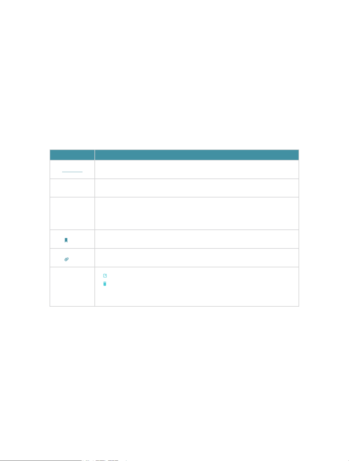
Conventions
In this guide, the following conventions are used:
Convention
Underline
Teal
>
Note:
Tips:
Symbols on
the web page
Description
Hyperlinks are in teal and underlined. You can click to redirect to a website
or a specific section.
Key information appears in teal, including management page text such as
menus, items, buttons and so on.
The menu structures to show the path to load the corresponding page. For
example, Advanced > Wireless > MAC Filtering
function page is under the Wireless menu that is located in the Advanced
tab.
Ignoring this type of note might result in a malfunction or damage to the
device.
Indicates important information that helps you make better use of your
device.
click to edit the corresponding entry.
•
•
click to delete the corresponding entry.
•
click to enable or disable the corresponding entry.
•
click to view more information about items on the page.
Speed/Coverage Disclaimer
means the MAC Filtering
Maximum wireless signal rates are the physical rates derived from IEEE Standard 802.11
specifications. Range, coverage, and maximum quantity of connected devices are
based on test results under normal usage conditions. Actual wireless data throughput,
wireless coverage, and quantity of connected devices are not guaranteed and will vary
as a result of 1) environmental factors, including building materials, physical objects,
and obstacles, 2) network conditions, including local interference, volume and density
of traffic, product location, network complexity, and network overhead, and 3) client
limitations, including rated performance, location, connection quality, and client
condition.
*Use of MU-MIMO requires clients to also support MU-MIMO.
1
Page 7

More Info
• The latest firmware and management app are available from the Download Center at
https://www.tp-link.com/support/download/.
• The Quick Installation Guide (QIG) can be found where you find this guide or inside the
product packaging.
• Specifications can be found on the product page at https://www.tp-link.com.
• TP-Link Community is provided for you to share knowledge and discuss our products
at https://community.tp-link.com.
• Our Technical Support contact information can be found at the Contact Technical
Support page at https://www.tp-link.com/support.
2
Page 8

Chapter 1
Get to Know Your Modem Router
This chapter introduces the modem router by detailing its main features and appearance.
It contains the following sections:
• Product Overview
• Physical Appearance
Page 9

Chapter 1
1. 1. Product Overview
TP-Link’s modem router is a combined wired/wireless network connection device with
wireless router and DSL modem capabilities.
With DSL and LAN/WAN ports, the modem router is compatible with DSL connections
and fiber/cable access.
Ethernet ports and adjustable antennas enable the modem router to provide wired and
wireless access for multiple computers and mobile devices.
With an array of additional features, the modem router is the perfect hub for your home
or business network.
1. 2. Physical Appearance
1. 2. 1. Top Panel
LED On/Off Button
The modem router’s LEDs are located on the top panel. You can check the modem
router’s working status by following the LED Explanation table.
It also provides the LED On/Off button. You can press the button to turn on/off the LEDs
without affecting the modem router’s function.
4
Page 10
Chapter 1
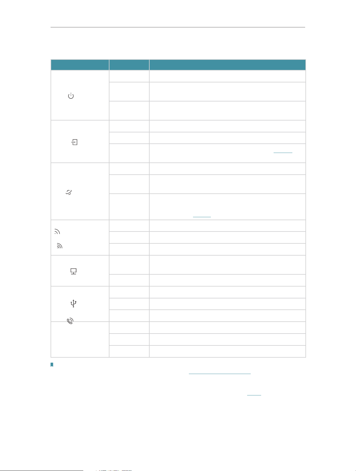
LED Explanation
Name Status
Power
DSL
Internet
Wireless 2.4GHz
/
Wireless 5GHz
Indication
On The system has started up successfully.
Flashing
Off
On DSL synchronization is complete.
Flashing DSL synchronization is in progress.
Off
Solid White Internet service is available.
Solid
Orange
Off
On The wireless 2.4GHz/5GHz band is working properly.
Flashing WPS connection is in progress (about 2 minutes).
Off The wireless 2.4GHz/5GHz band is disabled.
The system is starting up or firmware is being upgraded.
Do not disconnect or power off your modem router.
Power is off. Please ensure that the power adapter is
connected correctly.
DSL synchronization failed. Please refer to Note 1 for
troubleshooting.
DSL synchronization is complete but internet service is
unavailable.
Internet connection is incorrect, DSL synchronization
failed, or the modem router is operating in Bridge mode.
Please refer to Note 2 for troubleshooting.
On
LAN
At least one LAN port is connected to a powered-on
device.
Off No LAN port is connected to a powered-on device.
On The USB device is ready to use.
USB
Flashing The USB device is being identified.
Off No USB device is plugged into the USB port.
On The phone is off-hook or DECT handset is busy.
Phone
Flashing The phone is ringing or DECT handset is registering.
Off The phone is on-hook.
Note:
1. If the DSL LED is off, please check your internet connection. Refer to Connect Your Modem Router for more information about
how to connect to the internet correctly. If you have already made a successful connection, please contact your ISP to make
sure your internet service is available now.
2. If the Internet LED is off, please check your DSL LED first. If your DSL LED is also off, please refer to Note 1. If your DSL LED is ON,
reconnect your modem router correctly by referring to related guide.
5
Page 11

Chapter 1
1. 2. 2. Back Panel
The modem router’s back panel shows the ports, buttons and antennas. Refer to the
following for detailed instructions.
Item
Phone1/Phone2
DSL
DECT
LAN1, LAN2, LAN3,
LAN4/WAN
Power
Reset
Antennas
For connecting your analog phone to the modem router. Connect your
analog phones to the RJ11 ports on the back panel.
For connecting the modem router to the internet. Connect the port to
the splitter or directly connect the port to the phone jack via a phone
cable. For details, please refer to Connect Your Modem Router.
Press and hold for about 3 seconds until the Phone LED flashes to
register your DECT handset.
Press briefly to page your registered DECT handsets.
For connecting the modem router to your PC or other Ethernet network
devices. In wireless router mode, the LAN4/WAN port is used for
connecting to a Cable/FTTH/VDSL/ADSL device.
For connecting the modem router to power socket via the provided
power adapter.
Press and hold down for 10 seconds to reset the modem router to
factory default settings.
Used for wireless operation and data transmit. Upright them for the
best Wi-Fi performance.
Description
6
Page 12

Chapter 1
1. 2. 3. Side Panel
The modem router’s side panel shows the buttons and ports. Refer to the following for
detailed instructions.
Item
Power On/Off The switch for the power. Press it to power on or off the modem router.
USB For connecting to a USB storage device.
WPS Press to start a WPS synchronization.
Wi-Fi Press to turn both 2.4GHz and 5GHz Wi-Fi on or off.
Description
7
Page 13

Chapter 2
Connect the Hardware
This chapter contains the following sections:
• Position Your Modem Router
• Connect Your Modem Router
Page 14

Chapter 2
Connect the Hardware
2. 1. Position Your Modem Router
With the modem router, you can access your network from anywhere within the
wireless network coverage. However, the wireless signal strength and coverage varies
depending on the actual environment where your modem router is in. Many obstacles
may limit the range of the wireless signal, for example, concrete structures, thick walls.
For your security and best Wi-Fi performance, please:
• Do Not locate the modem router in the place where it will be exposed to moisture or
excessive heat.
• Keep away from the strong electromagnetic radiation and the device of
electromagnetic sensitive.
• Place the modem router in a location where it can be connected to the various devices
as well as to a power source.
• Make sure the cables and power cord are safely placed out of the way so they do not
create a tripping hazard.
• Keep the outside two antennas be outward at about 30 degrees (recommended).
• Generally, the router is placed on a horizontal surface, such as on a shelf or desktop.
The device also can be mounted on the wall as shown in the following figure.
Tips:
The diameter of the screw head, 5mm<D<8mm, and the distance of two screws is 84mm. The screw that project from
the wall need around 3mm based, and the length of the screw need to be at least 20mm to withstand the weight of the
product.
9
Page 15
Chapter 2
Connect the Hardware
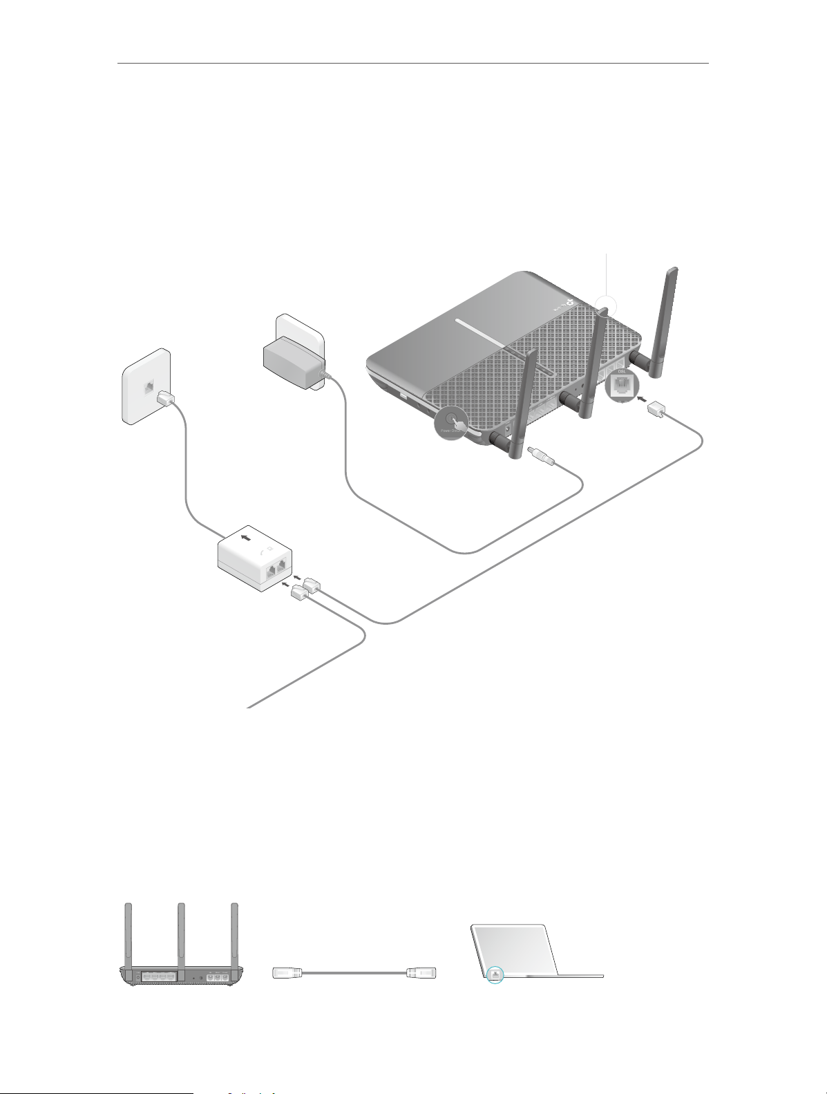
2. 2. Connect Your Modem Router
Follow the steps below to connect your modem router.
1. Connect the DSL line and power adapter. The electrical outlet shall be installed
near the device and shall be easily accessible.
Attach the antennas.
1
Phone2
Phone1
DSL
DECT
Reset
Modem Router
Phone Jack
Power Adapter
USB
WPS
WLAN
Push in to turn on the
4
modem router.
Connect the DSL splitter to the phone jack.
2
Note: If you won’t use the traditional landline phone service, you
can directly connect the modem router to the phone jack.
Connect the modem router
LINE
PHONE MODEM
DSL Splitter
For traditional landline phone service
3
to the DSL splitter.
2. Connect your computer to the modem router.
Method 1: Wired
Connect your computer’s Ethernet port to the LAN port on the modem router via the
Ethernet cable.
LAN
DECTReset
10
Page 16
Chapter 2
Connections are available
Wireless Network Connection
Connect the Hardware
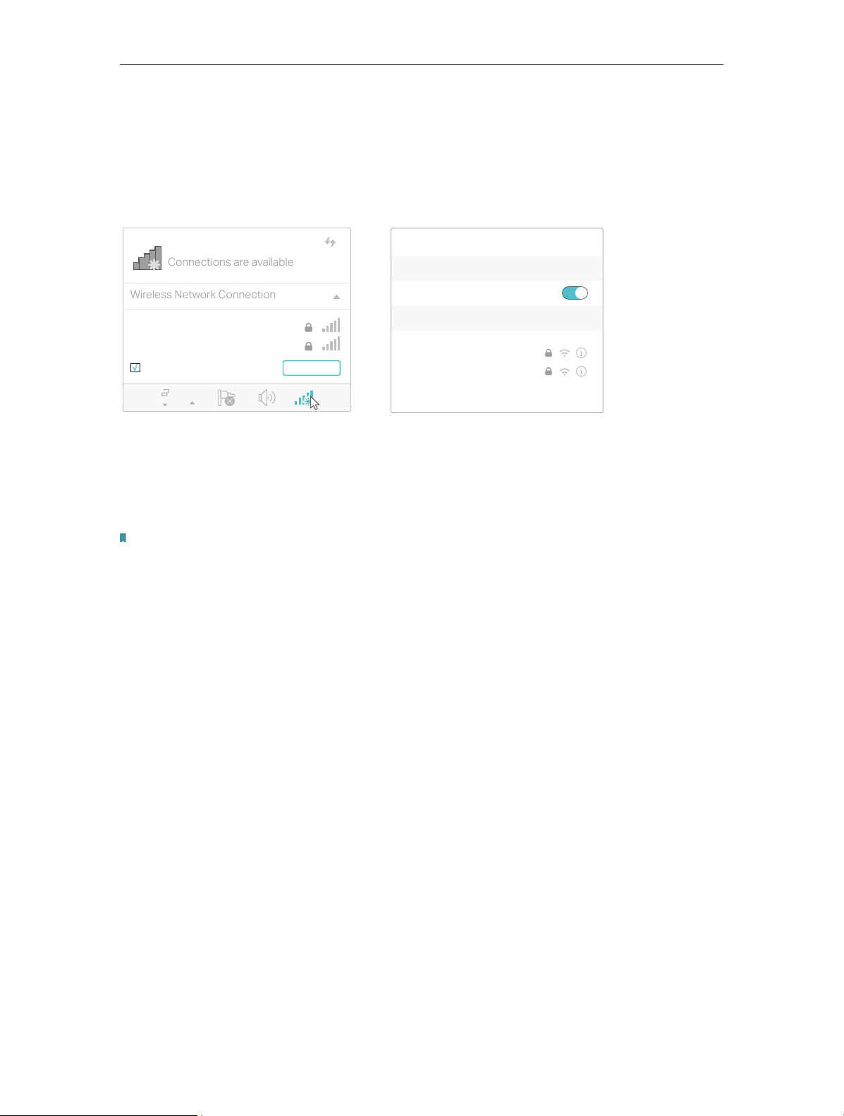
Method 2: Wirelessly
Use the default SSID (Wireless Network Name) and Wireless Password printed on
the included Wi-Fi Info Card or on the product label of the modem router to connect
wirelessly.
Computer Smart Device
Wi-Fi
TP-Link_XXXX
TP-Link_XXXX_5G
√
Connect automatically Connect
< Settings
Wi-Fi
CHOOSE A NETWORK...
TP-Link_XXXX
TP-Link_XXXX_5G
Other...
Method 3: Use the WPS button
Wireless devices that support WPS, including Android phones, tablets, most USB
network cards, can be connected to your router through this method. (WPS is not
supported by iOS devices.)
Note:
The WPS function cannot be configured if the wireless function of the router is disabled. Also, the WPS function will be
disabled if your wireless encryption is WEP. Please make sure the wireless function is enabled and is configured with the
appropriate encryption before configuring the WPS.
1 ) Tap the WPS icon on the device’s screen.
2 ) Immediately press the WPS button on your modem router.
3 ) The wireless LEDs flash for about two minutes during the WPS process.
4 ) When the wireless LEDs stabilize and remain on, the client device has
successfully connected to the modem router.
11
Page 17

Chapter 3
Log In to Your Modem Router
Page 18
Chapter 3
Log In to Your Modem Router
With the web management page, it is easy to configure and manage the modem router.
The web management page can be used on any Windows, Macintosh or UNIX OS with a
Web browser, such as Microsoft Internet Explorer, Mozilla Firefox or Apple Safari.
Follow the steps below to log in to your modem router.
1. If the TCP/IP Protocol on your computer is set to the static (fixed) IP address, you
need to change its settings to obtain an IP address automatically. Refer to Appendix:
Troubleshooting to configure your computer.
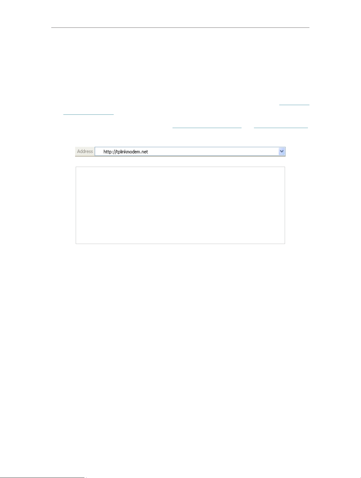
2. Launch a web browser and go to http://tplinkmodem.net or http://192.168.1.1.
Create a strong password and click Let’s Get Started to log in.
13
Page 19

Chapter 4
Set Up Internet Connections
This chapter introduces how to connect your modem router to the internet. The
modem router is equipped with a web-based Quick Setup wizard. It has many ISP
information built in, automates many of the steps and verifies that those steps have
been successfully completed. Furthermore, you can also set up an IPv6 connection if
your ISP provides IPv6 service.
This chapter includes the following sections:
• Use Quick Setup Wizard
• Manually Set Up an Internet Connection
• Test Internet Connectivity
• Set Up an IPv6 Connection
• More Operation Modes
Page 20

Chapter 4
Set Up Internet Connections
4. 1. Use Quick Setup Wizard
1. Visit http://tplinkmodem.net, and log in with the password you set for the modem
router.
2. Click Quick Setup on the top of the page. Then follow the step-by-step instructions
to connect your router to the internet.
3. To enjoy a more complete service from TP-Link (remote management, TP-Link
DDNS, etc.), log in with your TP-Link ID or click Register Now to get one. Then follow
the instructions to bind the modem router to your TP-Link ID.
Note:
1. To learn more about the TP-Link Cloud service, please refer to the TP-Link Cloud section.
2. If you do not want to register a TP-Link ID for now, you may click Log In Later to proceed.
3. If you have changed the preset wireless network name (SSID) and wireless password during the Quick Setup process, all your
wireless devices must use the new SSID and password to connect to the router.
4. 2. Manually Set Up an Internet Connection
1. Visit http://tplinkmodem.net, and log in with your TP-Link ID or the password you
set for the modem router.
2. Go to Basic > Internet page. Select your ISP, and related information will be
automatically filled in. For some ISPs, you may need to manually specify some
information provided. If you can’t find your ISP in the ISP List, select Other and then
enter the information provided by your ISP.
15
Page 21

Chapter 4
Set Up Internet Connections
3. Click Save to make the settings effective, and you can refer to Test Internet
Connectivity to test the internet connection.
Tips: You can view and edit all internet connection settings on the Advanced > Network > Internet page.
4. 3. Test Internet Connectivity
After manually setting up the internet connection, you need to test the internet
connectivity. The modem router provides a diagnostic tool to help you locate the source
of any problems.
1. Visit http://tplinkmodem.net, and log in with your TP-Link ID or the password you
set for the modem router.
2. Go to Advanced > System Tools > Diagnostics page.
16
Page 22

Chapter 4
Set Up Internet Connections
3. Click Start to test the internet connectivity and you will see the test result in the
gray box.
4. 4. Set Up an IPv6 Connection
If your ISP has provided a DSL line that supports IPv6 connection as well as some
detailed IPv6 parameters, you can manually set up an IPv6 connection.
If your ISP provides an IPv4-only connection or IPv6 tunnel service, permit IPv6
connection by referring to Set Up the IPv6 Tunnel.
Follow the steps below to set up an IPv6 connection:
1. Make sure you have set up an IPv4 connection either manually or by using the Quick
Setup wizard before setting up an IPv6 connection.
2. Visit http://tplinkmodem.net, and log in with your TP-Link ID or the password you
set for the modem router.
3. Go to Advanced > Network > Internet page.
4. Select your WAN Interface Name (Status should be Connected) and click the
(Edit) icon.
17
Page 23

Chapter 4
Set Up Internet Connections
5. Scroll down the page, enable IPv6, and configure the IPv6 parameters.
• Addressing Type: Consult your ISP for the addressing type (DHCPv6 or SLAAC).
SLAAC is the most commonly used addressing type.
• IPv6 Gateway: Keep the default setting as Current Connection.
Note: If your ISP has provided the IPv6 address, click Advanced to reveal more settings. Check to use IPv6
specified by ISP and enter the parameters provided by your ISP.
6. Click OK to make the settings effective. Now IPv6 service is available for your
network.
4. 5. More Operation Modes
The modem router supports two more operation modes: Wireless Router mode and
3G/4G Router mode. You can change the mode according to your needs.
4. 5. 1. Wireless Router Mode
If you already have a modem or your internet comes via an Ethernet jack on the wall, you
can set up the modem router as a regular wireless router to share the internet.
1. Find the WAN port (labeled as LAN4/WAN) on the modem router, and connect it
to your existing modem or the Ethernet jack on the wall. Then connect the power
adapter and turn on the modem router. If you connect an existing modem, reboot it
to get the modem router connected to the internet.
2. Connect your computer to the modem router. For details, refer to Connect Your
Modem Router.
3. Visit http://tplinkmodem.net, and log in with your TP-Link ID or the password you
set for the modem router.
4. Go to Advanced > Operation Mode, select the Wireless Router Mode, and click
Save. The modem router will reboot.
18
Page 24

Chapter 4
Set Up Internet Connections
5. Go to Basic > Internet, select the Connection Type, and enter the information
provided by your ISP.
6. Click Save to make the settings effective.
Tips:
1. You can view and edit all internet connections on Advanced > Network > Internet page.
2. In the Wireless Router Mode, you can also permit IPv6 connection by setting up an IPv6 connection or the IPv6 tunnel just as in
the DSL Modem Router Mode. For details, refer to Set Up an IPv6 Connection and Set Up the IPv6 Tunnel.
4. 5. 2. 3G/4G Router Mode
The modem router can be used as a 3G/4G wireless router if you have a 3G/4G USB
modem. There are two ways to use your 3G/4G network:
• As a backup solution for internet access
Use this way if you have set up an internet connection successfully and want to use the
3G/4G network as a backup network. Your modem router will be directly connected to
the 3G/4G network when the original network service fails. For detailed instructions,
refer to As a Backup Solution for Internet Access.
• As the only way to access the internet
Use this way if wired internet access is not available and you can only use the 3G/4G
network to access the internet. For detailed instructions, refer to As the Only Way to
Access the Internet.
Tips:
In the 3G/4G Router Mode, you can also permit IPv6 connection by setting up the IPv6 tunnel just as in the DSL Modem
Router Mode. For details, refer to Set Up the IPv6 Tunnel.
19
Page 25

Chapter 5
TP-Link Cloud Service
TP-Link Cloud service provides a better way to manage your cloud devices. Log in to
your router with a TP-Link ID, and you can easily monitor and manage your home network
when you are out and about via the Tether app on your smartphone or tablet. To ensure
that your router stays new and gets better over time, the TP-Link Cloud will notify you
when an important firmware upgrade is available. Surely you can also manage multiple
TP-Link Cloud devices with a single TP-Link ID.
This chapter introduces how to register a new TP-Link ID, bind or unbind TP-Link IDs
to manage your router, and the Tether app with which you can manage your home
network no matter where you may find yourself.
It contains the following sections:
• Register a TP-Link ID
• Change Your TP-Link ID Information
• Manage the User TP-Link IDs
• Manage the Router via TP-Link Tether App
Page 26

Chapter 5
TP-Link Cloud Service
5. 1. Register a TP-Link ID
If you have skipped the registration during the Quick Setup process, you can:
1. Visit http://tplinkmodem.net, and log in with the account you set for the router.
2. Go to Basic > TP-Link Cloud.
3. Click Register Now and follow the instructions to register a TP-Link ID.
4. After activating your TP-Link ID, come back to the TP-Link Cloud page to log in. The
first-time login TP-Link ID will be bound automatically to your cloud router as an
Admin.
Note:
• To learn more about the Admin and User TP-Link ID, refer to Manage the User TP-Link IDs.
• You can register another TP-Link ID via the Tether APP. Please refer to Manage the Router via TP-Link Tether App to
install the app and register a new one
• If you want to unbind the admin TP-Link ID from your router, please go to Basic > TP-Link Cloud, click Unbind in the
Device Information section.
5. 2. Change Your TP-Link ID Information
Follow the steps below to change your email address and password of your TP-Link ID
as needed.
1. Visit http://tplinkmodem.net, and log in with your TP-Link ID.
2. Go to Basic > TP-Link Cloud, and focus on the Account Information section.
¾ Change your email address
1. Click
behind the Email.
2. Enter the password of your TP-Link ID, then the new email address. And click Save.
21
Page 27

Chapter 5
¾ Change your password
TP-Link Cloud Service
1. Click
2. Enter the current password, then a new password twice. And click Save.
behind the Password.
5. 3. Manage the User TP-Link IDs
The first-time login TP-Link ID will be bound automatically to your router as an Admin
account. An admin account can add or remove other TP-Link IDs to the same router
as Users. Admin account and User accounts both can monitor and manage the router
locally or remotely, except that user accounts cannot:
• Reset the router to its factory default settings from the web management page or the
Tether app.
22
Page 28

Chapter 5
TP-Link Cloud Service
• Add/remove other TP-Link IDs to/from the router.
5. 3. 1. Add an TP-Link ID to Manage the Router
1. Visit http://tplinkmodem.net, and log in with your TP-Link ID.
2. Go to Basic > TP-Link Cloud, and focus on the Bound Accounts section.
3. Click
Note:
If you need another TP-Link ID, please refer to Manage the Router via TP-Link Tether App to install the app and register
a new one.
, enter another TP-Link ID as needed and click Save.
4. The new TP-Link ID will be displayed in the Bound Accounts table as a User.
5. 3. 2. Remove TP-Link ID(s) From Managing the Router
1. Visit http://tplinkmodem.net, and log in with your TP-Link ID.
2. Go to Basic > TP-Link Cloud, and focus on the Bound Accounts section.
3. Check the box(es) of the TP-Link ID(s) you want to remove and click Unbind.
23
Page 29
Chapter 5
TP-Link Cloud Service
5. 4. Manage the Router via TP-Link Tether App
The Tether app runs on iOS and Android devices like smartphones and tablets.
1. Open the Apple App Store or Google Play and search the key word TP-Link Tether or
simply scan the QR code to download and install the app.
OR
2. Open the Tether app and log in with your TP-Link ID. If you don’t have an account,
create one first.
3. Connect your device to the router’s wireless network.
4. Select the model of your router and manage your router as needed.
24
Page 30

Chapter 6
Telephony
This chapter guides you on how to make telephone calls via internet.
• Connecting the Telephone
• DECT
• Entering Telephone Information
• Telephone Book
• Telephony Devices Management
• Call Log
• Calling via Which Number
• Call Blocks
• Forwarding Calls
• Call Through
• tpPhone
• Voice Mail
Page 31

Chapter 6
Telephony
6. 1. Connecting the Telephone
Connect your telephone to the TAE ports on the side panel or RJ11 ports on the back
panel. Please note that you can only connect to two ports (one to a Phone 1 and the
other to a Phone 2) at most.
Phone 2Phone 1
RJ-11
6. 2. DECT
The modem router is integrated with DECT (Digital Enhanced Cordless
Telecommunications) function. With this function enabled, you can register your
cordless phone on the modem router and make calls via internet.
6. 2. 1. Registering DECT Handset
There are two ways to register your DECT handset.
Method 1: Via DECT Button
1. Set your DECT handset in the registration mode, and then press and hold the DECT
button on the DSL router for about 3 seconds until the Phone LED
DECT
DECTWLANWPSResetPower On/Off
flashes.
Within 1 minute
DECT
Press for 3 seconds
Blinking
26
Page 32

Chapter 6
Telephony
2. Enter the PIN (Default: 0000) on the DECT handset if required.
Notes:
1. Up to six DECT handsets can be registered on the modem router.
2. If you press the DECT button for more than 4 seconds, and the Phone LED still does not light, release the button and try again.
Method 2: Via Web Management Interface
Follow the steps below to register:
1. Visit http://tplinkmodem.net, and log in with your TP-Link ID or the password you
set for the router.
2. Go to Advanced > Telephony > Telephony Devices to open the registration page.
3. Click Register New DECT Handset and follow instructions on the page to register
your DECT handset.
6. 2. 2. Configuring DECT Settings
Configure DECT settings on the web management page of the modem router.
Follow the steps below to configure:
1. Visit http://tplinkmodem.net, and log in with your TP-Link ID or the password you
set for the router.
2. Go to Advanced > Telephony > DECT, and you will see the following screen.
27
Page 33

Chapter 6
Telephony
3. Enable DECT.
4. The PIN code is needed when registering your cordless phone. The default is 0000.
Change it by entering a new one.
5. Reduce DECT field strength: Check the box to enable this function. In this mode,
base transmit power will be decreased. Then the DECT Handset will have signal
within a small distance.
6. Eco DECT: Only when all handsets support Eco Mode, will it take effect. In this
mode, if all the handsets standby for more than one minutes, DECT Base and
DECT Handsets would be in Eco Mode and do not emit any signal. It will wake up
automatically when there is a call.
7. Security: Check the box if you want the DECT/CAT-iq encrypt security to take effect.
8. Click Save to make the settings effective.
6. 3. Entering Telephone Information
Before using telephony services, you should first enter your telephone information
provided by your telephony service provider.
Follow the steps below to enter information:
1. Visit http://tplinkmodem.net, and log in with your TP-Link ID or the password you
set for the router.
2. Go to Advanced > Telephony > Telephone Numbers to open the configuration page.
Click Add and you will see the following screen.
28
Page 34

Chapter 6
Telephony
3. Choose your Telephony Provider and enter the necessary information as required,
and click Save to make the settings effective.
4. If your telephony provider is not listed here, choose Other provider, enter the
information as required, and click Save to make the settings effective.
Phone Number: The number you use to dial and answer.
Registrar Address: Usually a domain name, if not, an IP address.
Authentication ID and Password: Not necessary information, but if you have, fill them in.
Area Code: The area code of your city or region.
29
Page 35

Chapter 6
Telephony
Advanced: Click to have more configuration.
5. In the Area Code section, enable this function and enter the area code of your city
or region. This can spare you the trouble of including the area code each time you
make a local call over the internet.
6. Click Save to make the settings effective.
Advanced: Click to have more configuration.
To have more configuration on telephony settings
Click Advanced under Advanced Settings to configure more telephony settings.
Bound Interface: Bound Interface decides where to send/receive the VoIP traffic. An
easy way to select the interface is to check the location of the SIP (Session Initiation
Protocol) server. If it locates somewhere on the internet then select Any_WAN. If it is on
the local network, select LAN.
Locale Selection: Select a country where you are located. The modem router is
embedded with some default parameters according to different countries such as ring
tones. The default country is Germany.
DSCP for SIP/RTP: DSCP (Differentiated Services Code Point) is the first 6 bits in
the ToS byte. DSCP marking allows users to assign specific application traffic to be
executed in priority by the next Router based on the DSCP value. Select DSCP for the
SIP (Session Initiation Protocol) and RTP (Real-time Transport Protocol) respectively. If
you are unsure, please always keep the default value.
30
Page 36

Chapter 6
DTMF Relay Setting: DTMF is Dual Tone Multi Frequency. Options available are SIP-Info,
RFC2833, and In-band. If you are unsure which one to choose, please always keep the
default value.
• SIP INFO: If it is selected, the modem router will capture the DTMF tone and transfer it
into SIP form. Then it will be sent to the remote end with SIP message.
• RFC2833: If it is selected, the modem router will capture the keypad number you
pressed and transfer it into digital form then send to the other side; the receiver will
generate the tone according to the digital form it receives. This function is very useful
when the network traffic congestion occurs and it still can remain the accuracy of
DTMF tone.
• In-band: If it is selected, the modem router will send the DTMF tone as audio directly
when you press the keypad on the phone.
Registry Expiration Time: Expiration time for the registration message sending.
Registration Retry Interval: Set the time duration for your SIP Registrar server to keep
your registration record. Before the time expires, the Modem Router will send another
register request to SIP Registrar again. If you are unsure of it, please always keep the
default value.
Telephony
“No answer“ Time: Set a time period, after which the caller is told that the call is not
answered and he or she can leave a message if the voice mail function is enabled.
T 38 support: Select the checkbox to enable this function. T 38 specifies a protocol for
transmitting a fax across IP network in real time. It allows the transfer of fax documents
in real-time between two standard Group 3 facsimile terminals over the internet or other
networks using IP protocols. It will only function when both sites support this feature
and are enabled.
End With ’#’: Choose whether to use “#” as the end signal of your dialing or not.
When the Status column change to
registered. At this time, you can pick up your phone, dial the number, and call via internet!
, your telephone information is successfully
6. 4. Telephone Book
You can store all contacts on your modem router, have a telephone book, set speed dial
number for some contacts and enable emergency calls.
6. 4. 1. Telephone Book
Follow the steps below to have a telephone book on the modem router.
1. Visit http://tplinkmodem.net, and log in with your TP-Link ID or the password you
set for the router.
31
Page 37

Chapter 6
2. Go to Advanced > Telephony > Telephone Book. Click Add to enter a new contact’s
information.
Telephony
3. You can set speed dial number for certain numbers. Speed dial function allows you
to reach the desired party by dialing the reduced number of keys rather than a long
phone number.
4. Click OK to save the settings.
6. 4. 2. Emergency Calls
I want to:
How can I
do that?
Make my telephone automatically call a specific contact when
the handset is picked up but no operation is done within a period
of time. In this way the old, the kids, the patient or the pregnant
in house are able to send signals for help when emergencies
occur.
1. Visit http://tplinkmodem.net, and log in with your TP-Link ID
or the password you set for the router.
2. Go to Advanced > Telephony > Telephone Book.
32
Page 38

Chapter 6
3. Enable Emergency Number.
4. No Operation Time: Set how long should the telephone wait
before the first number is automatically dialed).
5. Emergency Number: Set the number to be automatically
reached. If more than one number is set, the modem router
will automatically call the next one if the previous is not
answered.
Telephony
6. Click Save to make the settings effective.
Done!
From now on, if you pick up your phone but do not dial within
the no operation time, your phone will automatically call the
emergency number!
6. 5. Telephony Devices Management
I want to:
How can I
do that?
Bind different telephony devices with different incoming and
outgoing call numbers, because I have more than one telephone
number and telephony device and I don’t want all telephones
ring at the same time when a number is called.
1. Visit http://tplinkmodem.net, and log in with your TP-Link ID
or the password you set for the router.
2. Go to Advanced > Telephony > Telephony Devices.
33
Page 39

Chapter 6
Telephony
3. Click to manage your telephony devices.
4. Device Name: Name the telephone device here.
5. Number for Outgoing Calls: Assign an outgoing number for
this phone.
6. Number for Incoming Calls: Tick the incoming number for
this phone.
7. VAD Support: VAD (Voice Activation Detection) prevents
transmitting the silence packets to consume the bandwidth. It
is also known as Silence Suppression, a software application
that ensures bandwidth when voice activity is activated.
8. Adjust the Speaker Gain slider to control the speaker sound.
9. Adjust the Mic Gain slider to control the speaker sound of
microphone.
34
Page 40

Chapter 6
Telephony
10. Click OK to make the settings effective.
Done!
Now your telephony devices are bound to different incoming
call numbers and outgoing call numbers.
Tips:
Internal number showed on the table are used to make calls between telephony devices connected to the same modem
router. It is preset and cannot be changed.
6. 6. Call Log
I want to:
How can I
do that?
Have a call list recording detailed information of incoming calls
and outgoing calls on your modem router.
1. Visit http://tplinkmodem.net, and log in with your TP-Link ID
or the password you set for the router.
2. Go to Advanced > Telephony > Call Log.
3. Enable Call Log.
Done!
From now on, all calls in and out are recorded here. If you’ve
already had a telephone book, name of the contact would be
shown on the call list.
Tips:
You can enable Push Notification via E-mail for Missed Calls to have e-mail sent to you informing you of the latest events
that you are interested in, such as missed calls or voice mails. You should first go to Advanced > System Tools > Push
Service page to enable Push Notification via E-mail, and click to see the help page for detailed configuration about
Push Service.
6. 7. Calling via Which Number
I want to:
Use different outgoing numbers to call different types of
numbers.
For example, one of my phone number has a relatively low charge
in making long distance calls. I want all long distance calls to be
35
Page 41

Chapter 6
dialed via this number.
Telephony
How can I
do that?
1. Visit http://tplinkmodem.net, and log in with your TP-Link ID
or the password you set for the router.
2. Go to Advanced > Telephony > Call Rules. Click Add to set
call rules.
3. Choose Long Distance in Call Type or Prefix. Prefixes and call
types can vary according to your own circumstances.
4. In Number for Outgoing Calls, choose the number that has
low charge in making long distance calls.
5. Click OK to make the settings effective.
Done!
In addition:
From now on, whenever you are dialing a long distance call, the
call is made via the number you chose in step 5.
Call type can vary according to your circumstances. You can
also set prefix by choosing Calls with Specific Number Prefix in
Call Type or Prefix. When a prefix is set, all numbers with this
prefix is called via the assigned number.
6. 8. Call Blocks
When you do not want calls to be received or dialed, use call block functions. This part
consists of three functions: Do Not Disturb, Block Certain Calls and Prevent from Dialing.
6. 8. 1. Do Not Disturb
I want to:
Have no telephone ring at a certain period of time.
36
Page 42

Chapter 6
Telephony
How can I
do that?
1. Visit http://tplinkmodem.net, and log in with your TP-Link ID
or the password you set for the router.
2. Go to Advanced > Telephony > DND & Call Blocking.
3. Enable DND.
4. Set the day(s) when DND is enabled.
5. Click Save to make the settings effective.
Done!
Now, within this period of time, no telephone will ring, but all
incoming calls would be recorded in call log. Enjoy your peaceful
time and when you are back, check the call log to see what was
missed.
6. 8. 2. Blocking Certain Calls
I want to:
How can I
do that?
Block certain calls, for example, the anonymous calls, or calls
from the annoying salesmen.
1. Visit http://tplinkmodem.net, and log in with your TP-Link ID
or the password you set for the router.
2. Go to Advanced > Telephony > DND & Call Blocking.
3. Click Add under Incoming Calls.
4. Choose to block a specific number or anonymous calls.
37
Page 43

Chapter 6
5. Click OK to make the settings effective.
Telephony
Done!
From now on, these calls are all automatically blocked by your
modem router.
6. 8. 3. Prevent from Dialing
I want to:
How can I
do that?
Prevent my modem router from dialing a certain type of numbers.
For example, it costs a lot to call a mobile phone via my telephone
number, so I don’t want anyone to call a mobile phone using my
number.
1. Visit http://tplinkmodem.net, and log in with your TP-Link ID
or the password you set for the router.
2. Go to Advanced > Telephony > DND & Call Blocking.
3. Click Add under Outgoing Calls.
4. Choose to prevent mobile phone from being dialed. Number
type may vary according to your circumstances.
5. Click OK to make the settings effective.
Done!
In addition:
Now your modem router will prevent all mobile phone from being
dialed.
Number type may vary according to your circumstances. You
can also set prefix by choosing Calls with Specific Number Prefix.
When a prefix is set, all numbers with this prefix is prevented
from being called.
6. 9. Forwarding Calls
I want to:
Forward some incoming calls to a designated telephone number.
For example, when no one answers the incoming call, it would be
38
Page 44

Chapter 6
forwarded to my mobile phone so that I won’t miss it.
Telephony
How can I
do that?
1. Visit http://tplinkmodem.net, and log in with your TP-Link ID
or the password you set for the router.
2. Go to Advanced > Telephony > Call Forwarding. Click Add to
set how calls should be forwarded.
Done!
3. Select the incoming calls to be forwarded: Choose to forward
which call or call type.
4. Destination Telephone Number: Set the destination where
calls should be forwarded.
5. Forward the Calls via: Choose via which phone number the
calls will be forwarded.
6. Call Forward Condition: Choose the forwarding type
(Unconditional or No Answer) of the entry.
7. Click OK to make the settings effective.
Now your modem router will automatically forward the call
according to your rule.
39
Page 45

Chapter 6
6. 10. Call Through
Telephony
I want to:
How can I
do that?
Call someone through my telephone number registered on my
modem router.
For example, I am away from home, and want to call a friend who
is aboard. I can call the friend using my mobile phone of course,
but that would cost a huge sum. Meantime, my telephone
number has a low charge in making international calls. So it
would be great if I can call the friend using my mobile phone and
my telephone number. Fortunately, you can do that.
1. Visit http://tplinkmodem.net, and log in with your TP-Link ID
or the password you set for the router.
2. Go to Advanced > Telephony > Call Through. Enable Call
Through.
Done!
3. Number for Incoming: Select the number you are going to
use to call home via your mobile.
4. Number for Outgoing: Select the number you are going to
use to call your friend who is abroad.
5. If you tick Only Accept Calls from the Numbers below, you
should add numbers that are allowed to use Call Through
function on your modem router. In this example, add your
mobile number.
6. Click Save to make the settings effective.
Now you could follow the process below to call your friend using
your mobile phone and telephone number:
40
Page 46

Chapter 6
1. Use your mobile to call the incoming number you selected
in step 4.
2. Put in the PIN code when you hear the tone, remember to
end the PIN with a “#”. Change of the default PIN code is
recommended.
3. Dial the number of your friend.
4. At this time, your friend will receive a call from the outgoing
number your selected in step 5. You can talk to your friend
from your mobile phone.
Telephony
6. 11. tpPhone
tpPhone is an App allowing you to make and receive calls through VoIP modem router.
Follow the steps below to configure tpPhone settings:
1. Visit http://tplinkmodem.net, and log in with your TP-Link ID or the password you
set for the router.
2. Go to Advanced > Telephony > tpPhone and you will see the following screen.
3. Enable tpPhone and it is enabled by default.
4. The PIN code is used when registering tpPhone on the modem router. You can
change it by entering a new one in the field.
5. Click Save to make the settings effective.
You can go to the App Store or Google Play or scan the QR code below to download
tpPhone and start to make phones over the internet.
41
Page 47

Chapter 6
6. 12. Voice Mail
Telephony
I want to:
How can I
do that?
Allow the caller who is not answered to leave a voice mail.
For example, I’m on my vocation, and cannot receive any call at
the moment. If people who called can leave a voice mail, I would
know what was going on when I was absent from home.
1. Visit http://tplinkmodem.net, and log in with your TP-Link ID
or the password you set for the router.
2. Go to Advanced > Telephony > Voice Mail.
3. Enable Voice Mail.
42
Page 48

Chapter 6
Telephony
4. Set the “No answer“ Time. A time period. If the call is not
answered within this time period, the caller can leave a voice
mail.
5. Choose greetings for your Voice Mail. You can record the
greeting by dialing *30 on the keyboard of your telephone.
6. Set how long a voice mail can last at Voice Mail Duration.
7. If you want to access your voice mail remotely, enable
Remote Access Voice Mail and create a new Remote Access
PIN to make this function available. You need to enter this
new PIN when listening to your voice mails remotely.
8. You can enable Push Notification via E-mail for Voice Mails
to have e-mail sent to you informing you of voice mails. You
should first go to Advanced > System Tools > Push Service
page to enable Push Notification via E-mail, and click to see
the help page for detailed configuration about Push Service.
Done!
9. If you have inserted a USB storage device, you can enable
Expand Storage Capacity with USB Storage Device to save
voice mails to your USB storage device after the internal
flash is full.
10. Click Save to make the settings effective.
When a voice mail is recorded, the modem router will display it
in the following table.
There are three ways to listen to these voice mails.
• Click
• Press *20 on the telephone keyboard to listen.
on the table to listen.
• Dial the number of your telephone, press * when you hear the greeting
and follow the voice prompt to enter the Remote Access PIN to listen.
43
Page 49

Chapter 7
OneMesh with Seamless Roaming
This chapter introduces the TP-Link OneMeshTM feature.
It contains the following sections:
• Set Up a OneMesh Network
• Manage Devices in the OneMeshTM Network
Page 50

Chapter 7
OneMesh with Seamless Roaming
TP-Link OneMeshTM router and TP-Link OneMeshTM extenders work together to
form one unified Wi-Fi network. Walk through your home and stay connected with the
fastest possible speeds thanks to OneMesh’s seamless coverage.
Unified Wi-Fi Network
Router and extenders share the same wireless settings, including network name,
password, access control settings and more.
Seamless Roaming
Devices automatically switch between your router and extenders as you move
through your home for the fastest possible speeds.
Easy Setup and Management
Set up a OneMeshTM network with a push of WPS buttons. Manage all network devices
on the Tether app or at your router’s web management page.
Unified OneMeshTM Network
IN TER NE T
SAME
Network Name & Password
for Seamless Roaming
7. 1. Set Up a OneMesh Network
1. Visit http://tplinkmodem.net, and log in with your TP-Link ID or the password you set
for the router.
2. Go to Basic > OneMesh or Advanced > Wireless > OneMesh.
45
Page 51

Chapter 7
Note:
Early firmware versions may not support OneMeshTM. If you can’t find the OneMesh page, please upgrade your router
to the latest firmware version. For upgrade instructions, refer to Update the Firmware.
OneMesh with Seamless Roaming
3. Connect one or more OneMeshTM extenders to this router by following the setup
instructions in the extenders’ manuals.
Note:
To check full list of TP-Link OneMeshTM devices, visit https://www.tp-link.com/onemesh/compatibility.
4. If you have set up an extender to join the OneMeshTM network, it will be listed in the
Devices in OneMesh Network list. Otherwise, you need to find it in the Available
TM
OneMesh Devices list and click Add to add it to the OneMesh
network.
Now your router and extenders successfully form one OneMeshTM network!
7. 2. Manage Devices in the OneMeshTM Network
In a OneMeshTM network, you can manage all mesh devices and clients on your router’s
web page.
46
Page 52

Chapter 7
OneMesh with Seamless Roaming
• To view all mesh devices and clients in the OneMeshTM network:
1. Visit http://tplinkmodem.net, and log in with your TP-Link ID or the password you set
for the router.
2. Go to Basic > Network Map.
3. Click the Mesh Devices, Wired Clients, or Wireless Clients icon to view the related
device or client list.
• To manage each OneMeshTM device in the network:
1. Visit http://tplinkmodem.net, and log in with your TP-Link ID or the password you set
for the router.
2. Go to Basic > OneMesh or Advanced > Wireless > OneMesh.
47
Page 53

Chapter 7
OneMesh with Seamless Roaming
3. Click a OneMesh
TM
device to view the device information, or click <number> Clients
to view the clients connected to this device.
On the Device Info page, you can:
• Click Manage Device to redirect to the web mangement page of this OneMesh
device.
• Click Leave OneMesh to delete this device from the OneMesh
TM
network.
TM
48
Page 54

Chapter 8
IPTV
IPTV is the abbreviation of Internet Protocol Television. The service can only be delivered
through the Internet, and our modem router provides a specific LAN port for IPTV.
By automatically separating IPTV from Internet surfing, you can enjoy a high quality of
video streaming and fast browsing speeds at the same time.
Page 55

Chapter 8
I want to:
Configure the modem router to enable Internet Protocol Television (IPTV) Services.
For example, I already bought IPTV service, but this service can only be delivered
through the Internet. Therefore, I need to configure my modem router first.
How can I do that?
1. Visit http://tplinkmodem.net, and log in with your TP-Link ID or the password you
set for the router.
2. Go to Advanced > IPTV to open the configuration page.
3. Check Enable to enable IPTV function.
4. Select your ISP from the Profile drop-down listand and then the VLAN ID will be
automatically filled in. If your ISP is not listed, select Others and then configure your
VLAN ID using the parameters provided by your IPTV service provider.
5. Select a connection type from the Profile drop-down listand according to your IPTV
connection. If you select Bridge, specify a LAN port for the IPTV connection and
connect the set-top box to this port.
6. Click Save to make the settings effective.
Done!
Modem router configuration is complete! You may still need to configure settings on
your set-top box before enjoying your IPTV service.
50
Page 56

Chapter 9
Guest Network
This function allows you to provide Wi-Fi access for guests without disclosing your
main network. When you have guests in your house, apartment, or workplace, you can
create a guest network for them. In addition, you can assign network authorities and
bandwidth for guests to ensure network security, privacy, and fluency.
• Create a Network for Guests
• Customize Guest Network Options
Page 57

Chapter 9
Guest Network
9. 1. Create a Network for Guests
1. Visit http://tplinkmodem.net, and log in with your TP-Link ID or the password you
set for the router.
2. Go to Advanced > Guest Network. Locate the Wireless Settings section.
3. Create 2.4GHz and 5GHz guest network according to your needs.
1 ) Enable 2.4GHz Wireless or 5GHz Wireless or enable both according to your
needs.
2 ) Set an easy-to-identify SSID. Don‘t select Hide SSID unless you want your
guests and other people to manually input this SSID for Wi-Fi access.
3 ) Set Security to WPA/WPA2 Personal, keep the default Version and Encryption
values, and set an easy-to-remember password. 2.4GHz and 5GHz guest
networks share the same password.
4. Click Save. Now your guests can access your guest network using the SSID and
password you set!
Tips:
To view guest network information, go to Advanced > Status and find the Guest Network section.
9. 2. Customize Guest Network Options
1. Visit http://tplinkmodem.net, and log in with your TP-Link ID or the password you
set for the router.
2. Go to Advanced > Guest Network.
52
Page 58

Chapter 9
Guest Network
3. Assign network authorities and bandwidth according to your needs.
• Allow Guests to Access Each Other
Select this check box to allow the clients in your guest network to access each
other’s files.
• Allow Guests to Access My Local Network
Select this check box to allow the clients in your guest network to access your local
network, not just the internet.
• Allow Guests to Access My USB Storage Sharing
Select this check box to allow the clients in your guest network to access your
router’s USB storage sharing.
• Enable QoS for Guest Network
Select this check box to set the QoS Priority of the guest network. This option is
available only when QoS is enabled on the Advanced > QoS page.
4. Click Save. Now users in your guest network can enjoy only the network authorities
at the priority you assigned!
Tips:
To view guest network information, go to Advanced > Status and find the Guest Network section.
53
Page 59

Chapter 10
USB Settings
This chapter describes how to use the USB ports to share files, and media from the USB
storage devices over your home network locally, or remotely through the internet.
The modem router supports USB external flash drives, and hard drives.
This chapter contains the following sections:
• Access the USB Storage Device
• Media Sharing
• 3G/4G Settings
Page 60

Chapter 10
USB Settings
10. 1. Access the USB Storage Device
Insert your USB storage device into the modem router’s USB port and then access files
stored there locally or remotely.
Tips:
• If you use USB hubs, make sure no more than 4 devices are connected to the modem router.
• If the USB storage device requires using bundled external power, make sure the external power has been
connected.
• If you use a USB hard drive, make sure its file system is FAT32 or NTFS. Some modem routers also support
the HFS+ and exFAT file systems.
• Before you physically disconnect a USB device from the modem router, safely remove it to avoid data
damage: Go to Advanced > USB Sharing > USB Storage Device and click
10. 1. 1. Access the USB Device Locally
Insert your USB storage device into the modem router’s USB port and then refer to the
following table to access files stored on your USB storage device:
.
Windows
computer
• Method 1:
Go to Computer > Network, then click the Network Server Name
(ARCHER_model number by default) in the Computer section.
Note:
1. Operations in different systems are similar. Here we take Windows 7 as an example.
2. Network Server Name can be customized on the web management page.
55
Page 61

Chapter 10
Windows
computer
• Method 2:
Open the Windows Explorer (or go to Computer) and type the server
address \\tplinkmodem.net or ftp://tplinkmodem.net in the address
bar, then press Enter.
1 ) Select Go > Connect to Server
USB Settings
Mac
2 ) Type the server address smb://tplinkmodem.net
3 ) Click Connect
4 ) When prompted, select the Guest radio box. (If you have set up
a username and a password to deny anonymous access to the
USB disks, you should select the Registered User radio box. To
learn how to set up an account for the access, refer to To Set up
Authentication for Data Security.)
Tips:
You can also use the FTP, http and SFTP methods to access the USB storage device.
Tablet
Use a third-party app for network files management.
10. 1. 2. Access the USB Device Remotely
You can access your USB disk outside the local area network. For example, you can:
56
Page 62

Chapter 10
USB Settings
• Share photos and other large files with your friends without logging in to (and paying
for) a photo-sharing site or email system.
• Get a safe backup for the materials for a presentation.
• Save and remove the files on your camera’s memory card during your travels.
Note:
If your ISP assigns a private WAN IP address (such as 192.168.x.x or 10.x.x.x), you cannot use this feature because
private addresses are not routed on the internet.
Follow the steps below to configure remote access settings.
1. Visit http://tplinkmodem.net, then log in with your TP-Link ID or the password you
set for the modem router.
2. Go to Advanced > USB Sharing > USB Storage Device page and locate the Sharing
Settings section.
3. Select the check box to enable FTP (via Internet), or https (via Internet), or SFTP (via
Internet), then click Save.
4. Refer to the following table to access your USB disk remotely.
57
Page 63

Chapter 10
Windows
computer
USB Settings
1 ) Open the Windows Explorer (or go to Computer, only for
Windows users) or open a web browser.
2 ) Type the server address in the address bar:
Type in ftp://<WAN IP address of the modem router>:<port
number> (such as ftp://59.40.2.243:21). If you have specified
the domain name of the modem router, you can also type
in ftp://<domain name>:<port number> (such as ftp://
MyDomainName:21)
3 ) Press Enter on the keyboard.
4 ) Access with the username and password you set in To Set up
Authentication for Data Security.
Tips:
You can also access the USB disk via a third-party app for network files management, which
can resume broken file transfers.
Tablet
Tips:
Click Set Up a Dynamic DNS Service Account to learn how to set up a domain name for your modem router.
Use a third-party app for network files management.
10. 1. 3. Customize the Access Settings
By default, all the network clients can access all folders on your USB disk. You can
customize your sharing settings by setting a sharing account, sharing specific contents
and setting a new sharing address on the modem router’s web management page.
1. Visit http://tplinkmodem.net, then log in with your TP-Link ID or the password you
set for the modem router.
2. Go to Advanced > USB Sharing > USB Storage Device page.
• To Customize the Address of the USB Disk
You can customize the server name and use the name to access your USB disk.
1. On the Sharing Settings part, make sure Network Neighborhood is ticked, and enter
a Network/Media Server Name as you like, such as MyShare, then click Save.
58
Page 64

Chapter 10
USB Settings
2. Now you can access the USB disk by visiting \\MyShare (for Windows) or smb://
MyShare (for Mac).
• To Only Share Specific Content
1. Focus on the Folder Sharing section. Click the button to disable Share All, then click
Add to add a new sharing folder.
2. Select the Volume Name and Folder Path, then enter a Folder Name as you like.
3. Decide the way you share the folder:
59
Page 65

Chapter 10
USB Settings
• Enable Authentication: Select to enable authentication for this folder sharing,
and you will be required to log in to the Sharing Account to access the USB disk.
Refer to To Set up Authentication for Data Security to learn more.
• Enable Write Access: If you tick this check box, network clients can modify this
folder.
• Enable Media Sharing: Tick to enable media sharing for this folder, and you can
view photos, play music and watch movies stored on the USB disk directly from
DLNA-supported devices. Refer to Media Sharing to learn more.
4. Click Save.
Tips:
The modem router can share eight volumes at most. You can click on the page to detach the corresponding volume
you do not need to share.
• To Set up Authentication for Data Security
You can set up authentication for your USB device so that network clients will be
required to enter the username and password when accessing the USB disk.
1. Under Sharing Account, choose Use Default Account or Use New Account. The
username and password are both admin for the default account. If your choose
Use New Account, you have to customize the username and a password.
Note:
For Windows users, do not set the sharing username the same as the Windows username. Otherwise, Windows
credential mechanism may cause the following problems:
• If the sharing password is also the same as the Windows password, authentication will not work since the Windows
system will automatically use its account information for USB access.
• If the sharing password is different from the Windows password, the Windows system will be unable to remember
your credentials and you will always be required to enter the sharing password for USB access.
60
Page 66

Chapter 10
USB Settings
2. Specify the folder(s) to enable authentication.
• If you want to enable authentication for all folders, leave Share All enabled, and
toggle on Enable Authentication.
• If you want to enable authentication for specific folders, disable Share All and
click Add to specify the folders, and select Enable Authentication.
Note:
Due to Windows credential mechanism, you might be unable to access the USB disk after changing Authentication
settings. Please log out from the Windows and try to access again. Or you can change the address of the USB disk by
referring to To Customize the Address of the USB Disk.
10. 2. Media Sharing
Media Sharing allows you to view photos, play music and watch movies stored on the
USB disk directly from DLNA-supported devices, such as your computer, tablet or
games console.
1. When your USB disk is inserted into the modem router, your DLNA-supported
devices (such as your computer and tablet) connected to the modem router can
detect and play the media files on the USB disks.
61
Page 67

Chapter 10
2. Refer to the following table for detailed instructions.
• Go to Computer > Network, then click the Media Server Name (Archer_
model number by default) in the Media Devices section.
Note:
Here we take Windows 7 as an example.
Windows
Computer
USB Settings
Smart
device
• Use a third-party DLNA-supported player.
10. 3. 3G/4G Settings
The modem router can be used as a 3G/4G wireless router if you have a 3G/4G USB
modem. There are two ways to use your 3G/4G network:
• As a backup solution for internet access
• As the only way to access the internet
10. 3. 1. As a Backup Solution for Internet Access
Using 3G/4G network as a backup solution for internet access, your modem router will
be directly connected to the 3G/4G network when the original network service fails.
Follow the steps below to set your 3G/4G network as a backup for internet access:
62
Page 68

Chapter 10
USB Settings
1. Plug your USB modem into the USB port of your modem router.
2. Visit http://tplinkmodem.net, then log in with your TP-Link ID or the password you
set for the modem router.
3. Go to Advanced > USB Settings > 3G/4G Settings, and select the box of Enable
3G/4G as a backup solution for Internet access.
4. Verify that your 3G/4G USB Modem is successfully identified.
Note:
The 3G/4G USB modem will not be identified if it is incompatible with the modem router. Find the 3G/4G Compatibility List
on the web page: http://www.tp-link.com/en/comp-list.html. If your USB modem is incompatible, contact our technical
support.
5. Verify that the modem router has correctly recognized your Mobile ISP. When your
Mobile ISP is correct, you have successfully set 3G/4G network as a backup solution
for internet access. Otherwise, select the box Set the Dial Number, APN, Username
and Password manually and enter the information provided by your 3G/4G network
service provider.
6. Click Advanced to have more configurations if needed.
7. Click Save to make the settings effective.
63
Page 69

Chapter 10
USB Settings
10. 3. 2. As the Only Way to Access the Internet
If you want the 3G/4G network to be your only way to access the internet, follow the
steps below to configure:
1. Plug your USB modem into the USB port of your modem router.
2. Visit http://tplinkmodem.net, and log in with your TP-Link ID or the password you
set for the modem router.
3. Go to Advanced > Operation Mode and choose 3G/4G Router Mode.
4. Click Save and when the modem router is successfully rebooted, the settings will
be effective.
5. Go to Advanced > USB Sharing > 3G/4G Settings.
6. Verify that your 3G/4G USB Modem is successfully detected.
Note:
If your 3G/4G USB modem is incompatible with the modem router, it will not be identified. Find the 3G/4G Compatibility
List on the web page: http://www.tp-link.com/en/comp-list.html. If your USB modem is incompatible, contact our
technical support.
7. Verify that the modem router has correctly recognized your Mobile ISP. When your
Mobile ISP is correct, you can enjoy the internet! Otherwise, select the box Set the
Dial Number, APN, Username and Password manually and enter the information
provided by your 3G/4G network service provider.
8. Select the Connection Mode. The default mode is Always on. You can choose
Connect on demand or Connect manually.
64
Page 70

Chapter 10
USB Settings
• If you choose Connect manually, you need to click the Connect or Disconnect
button to manually turn on or off the internet.
• If you choose Connect on demand, the network will automatically turn off when
there is no internet request in Max Idle Time, and turn on again when you try to
connect to the internet.
9. Click Advanced to have more configurations if needed.
10. Click Save to make the settings effective.
65
Page 71

Chapter 11
Parental Controls
This function allows you to block inappropriate, explicit and malicious websites and
limit internet access during specified time periods.
Page 72

Chapter 11
Parental Controls
I want to:
Control what types of websites my children or other home network users can visit and
the time of day they are allowed to access the internet.
For example, I want to allow my children’s devices (for example, a computer or a tablet)
to access only www.tp-link.com and wikipedia.org from 18:00 (6PM) to 22:00 (10PM) on
weekdays and not other time.
How can I do that?
1. Visit http://tplinkmodem.net, and log in with your TP-Link ID or the password you
set for the router.
2. Go to Basic or Advanced > Parental Controls and enable Parental Controls.
3. Click Add.
67
Page 73

Chapter 11
Parental Controls
4. Click Scan, and add the device to be controlled. Or, enter the Device Name and
MAC Address manually.
5. Click the
icon to set the Effective Time. Drag the cursor over the appropriate
cell(s) and click OK.
Note: The time of Parental Controls is based on the system time of the modem router. Please go to Advanced > System
Tools > Time Settings to set the correct time..
6. Enter a Description for the entry.
7. Select the check box to enable this entry and click OK.
8. Enable Content Restriction and select the restriction mode.
68
Page 74

Chapter 11
Parental Controls
1 ) In Blacklist mode, the controlled devices cannot access any websites containing
the specified keywords during the Effective Time period.
2 ) In Whitelist mode, the controlled devices can only access websites containing
the specified keywords during the Effective Time period.
9. Click Add a New Keyword. You can add many keywords for both Blacklist and
Whitelist. Below are some sample entries to allow access.
1 ) Enter a web address (for example, www.tp-link.com) or a web address keyword
(for example, wikipedia) to only allow or block access to the websites containing
that keyword.
2 ) Specify the domain suffix (for example, .edu or .org) to allow access only to the
websites with that suffix.
10. Enter the keywords or websites you want to add and click Save.
Done!
Now you can control your children’s internet access according to your needs.
69
Page 75

Chapter 12
QoS
This chapter explains how to create a QoS (Quality of Service) rule to prioritize your
online activities, which minimizes the impact caused by heavy internet traffic.
It contains the following sections:
• Prioritize Internet Traffic with QoS
• Update the Database
Page 76

Chapter 12
QoS
12. 1. Prioritize Internet Traffic with QoS
QoS (Quality of Service) is designed to ensure the efficient operation of the network
when network congestion is encountered.
I want to:
Specify priority levels for some devices or applications.
For example, I have several devices that are connected to my wireless network. I would
like to set an intermediate speed on the internet for my phone.
How can I do that?
1. Enable QoS and set bandwidth allocation.
1 ) Visit http://tplinkmodem.net, and log in with your TP-Link ID or the password
you set for the router.
2 ) Go to Advanced > QoS > Settings.
3 ) Select Enable QoS.
4 ) Choose your Line Type.
5 ) Input the maximum upload and download bandwidth provided by your internet
service provider. 1Mbps equals to 1000Kbps.
6 ) If you want to prioritize the IPTV traffic, select Enable, the IPTV Priority will be
high.
7 ) Click Advanced and drag the scroll bar to set the bandwidth priority percentage.
8 ) Click Save.
2. Add a middle priority QoS rule for the phone.
1 ) Click Add in the Middle Priority area and then select By Device and click Scan.
71
Page 77

Chapter 12
2 ) Choose the respective device from the list.
3 ) Click Save.
QoS
3. Refer to the steps above to apply other QoS rules if any.
Note:
If you want to delete a QoS rule, click to remove the responding rule from the list.
Done!
Now QoS is implemented to prioritize internet traffic.
12. 2. Update the Database
This function can help to add or update the applications the router supports. If the
applications you need are not listed in the Application list, you can try to download
the new version and upgrade the database. New database versions are posted at
www.tp-link.com and can be downloaded for free.
1. Download the latest QoS database from our website (www.tp-link.com).
2. Visit http://tplinkmodem.net, and log in with your TP-Link ID or the password you set
for the router.
72
Page 78

Chapter 12
QoS
3. Go to Advanced > QoS > Database. Click Browse to select the database upgrade file,
and then click Upgrade. Wait until the upgrade is complete and do not operate the
router during the process.
73
Page 79

Chapter 13
Network Security
This chapter guides you on how to protect your home network from unauthorized users
by implementing these five network security functions. You can protect the router from
cyber attacks using the Firewall, prevent certain users from accessing the specified
service, and even block internet access completely using Service Filtering, or use
Access Control to block or allow specific client devices to access your network. Or
you can prevent ARP spoofing and ARP attacks by using IP & MAC Binding and you can
protect your IPv6 network by preventing access from the internet using IPv6 Firewall.
• Firewall & DoS Protection
• Service Filtering
• Access Control
• IP & MAC Binding
• IPv6 Firewall
Page 80

Chapter 13
Network Security
13. 1. Firewall & DoS Protection
The SPI (Stateful Packet Inspection) Firewall and DoS (Denial of Service) Protection
protect the router from cyber attacks.
The SPI Firewall can prevent cyber attacks and validate the traffic that is passing
through the router based on the protocol. This function is enabled by default, and it’s
recommended to keep the default settings.
DoS Protection can protect your home network against DoS attacks from flooding your
network with server requests. Follow the steps below to configure DoS Protection.
1. Visit http://tplinkmodem.net, and log in with your TP-Link ID or the password you
set for the router.
2. Go to Advanced > Security > Firewall & DoS Protection.
3. Enable DoS Protection.
4. Set the level (Low, Middle or High) of protection for ICMP-Flood Attack Filtering,
UDP-Flood Attack Filtering and TCP-Flood Attack Filtering.
• ICMP-Flood Attack Filtering - Enable to prevent the ICMP (Internet Control
Message Protocol) flood attack.
• UDP-Flood Attack Filtering - Enable to prevent the UDP (User Datagram
Protocol) flood attack.
• TCP-Flood Attack Filtering - Enable to prevent the TCP (Transmission Control
Protocol) flood attack.
5. Click Save.
Tips:
1. The level of protection is based on the number of traffic packets. Specify the level at DoS Protection Level Settings.
75
Page 81

Chapter 13
2. The protection will be triggered immediately when the number of packets exceeds the preset threshold value, and
the vicious host will be displayed in the Blocked DoS Host List.
Network Security
13. 2. Service Filtering
With Service Filtering, you can prevent certain users from accessing the specified
service, and even block internet access completely.
1. Visit http://tplinkmodem.net, and log in with your TP-Link ID or the password you
set for the router.
2. Go to Advanced > Security > Service Filtering.
3. Toggle on Service Filtering.
4. Click Add.
76
Page 82

Chapter 13
Network Security
5. Select a Service Type from the drop-down list and the following four fields will be
auto-populated. Select Custom when your desired service type is not listed, and
enter the information manually.
6. Specify the IP address(es) that this filtering rule will apply to.
7. Click Save.
Note: If you want to disable this entry, click the icon.
13. 3. Access Control
Access Control is used to block or allow specific client devices to access your network
(via wired or wireless) based on a list of blocked devices (Blacklist) or a list of allowed
devices (Whitelist).
I want to:
Block or allow specific client devices to access my network (via wired or wireless).
How can I do that?
1. Visit http://tplinkmodem.net, and log in with your TP-Link ID or the password you
set for the router.
2. Go to Advanced > Security > Access Control and enable Access Control.
77
Page 83

Chapter 13
Network Security
3. Select the access mode to either block (recommended) or allow the device(s) in the
list.
To block specific device(s)
1 ) Select Blacklist and click Save.
2 ) Select the device(s) to be blocked in the Online Devices table.
3 ) Click Block above the Online Devices table. The selected devices will be added
to Devices in Blacklist automatically.
To allow specific device(s)
1 ) Select Whitelist and click Save.
2 ) Click Add.
78
Page 84

Chapter 13
1 ) Click San and the Device Name and MAC Address will be automatically filled in.
2 ) Click Save.
Or enter the Device Name and MAC Address manually.
Network Security
Done!
Now you can block or allow specific client devices to access your network (via wired or
wireless) using the Blacklist or Whitelist.
13. 4. IP & MAC Binding
IP & MAC Binding, namely, ARP (Address Resolution Protocol) Binding, is used to bind
a network device’s IP address to its MAC address. This will prevent ARP spoofing and
other ARP attacks by denying network access to a device with a matching IP address in
the Binding list, but an unrecognized MAC address.
I want to:
Prevent ARP spoofing and ARP attacks.
How can I do that?
1. Visit http://tplinkmodem.net, and log in with your TP-Link ID or the password you
set for the router.
2. Go to Advanced > Security > IP & MAC Binding and enable IP & MAC Binding.
3. Bind your device(s) according to your needs.
79
Page 85

Chapter 13
To bind the connected device(s)
1 ) Select the device(s) to be bound in the ARP List.
2 ) Click Bind to add to the Binding List.
To bind the unconnected device
1 ) Click Add.
Network Security
2 ) Enter the MAC Address and IP Address that you want to bind.
3 ) Select the check box to enable the entry and click OK.
Done!
Enjoy the internet without worrying about ARP spoofing and ARP attacks.
13. 5. IPv6 Firewall
IPv6 Firewall protects your IPv6 network by preventing access from the internet.
However, when you are hosting a service, such as a file sharing server in your local
network, you can choose to allow access to the server from the internet by adding
entries on this page. This feature is available only when you’ve set up an IPv6 connection.
1. Visit http://tplinkmodem.net, and log in with your TP-Link ID or the password you
set for the router.
2. Go to Advanced > Security > IPv6 Firewall.
3. Click Add.
80
Page 86

Chapter 13
Network Security
4. Select an interface name from the drop-down list. Interface names are names of
the internet connections you have set up.
5. Click Scan to select a service from the list to automatically populate the Port field
with an appropriate port number. It is recommended to keep the default Port if you
are unsure about which one to use. If the service is not listed, manually enter the
Service Type and the Port number (e.g., 21 or 21-25).
6. Click Scan to select the local host device running the service. If the device is not
listed, enter its global IPv6 address in the Internal IP field
7. Select a protocol for the service from the drop-down list.
8. Tick Enable This Entry and click Save.
Note: If you want to disable this entry, click the icon.
81
Page 87

Chapter 14
NAT Forwarding
Modem router’s NAT (Network Address Translation) feature makes the devices in the
LAN use the same public IP address to communicate in the internet, which protects the
local network by hiding IP addresses of the devices. However, it also brings about the
problem that external host cannot initiatively communicate with the specified device in
the local network.
The modem router can use a forwarding feature to remove the isolation of NAT and
allow external internet hosts to intuitively communicate with the devices in the local
network, thus enabling some special features.
TP-Link modem router includes four forwarding rules. If two or more rules are set, the
priority of implementation from high to low is Virtual Servers, Port Triggering, UPNP and
DMZ.
This chapter contains the following sections:
• Translate Address and Port by ALG
• Share Local Resources over the Internet by Virtual Server
• Open Ports Dynamically by Port Triggering
• Make Applications Free from Port Restriction by DMZ
• Make Xbox Online Games Run Smoothly by UPnP
Page 88

Chapter 14
NAT Forwarding
14. 1. Translate Address and Port by ALG
ALG (Application Layer Gateway) allows customized NAT (Network Address Translation)
traversal filters to be plugged into the gateway to support address and port translation
for certain application layer “control/data” protocols: FTP, TFTP, H323 etc. Enabling ALG
is recommended.
1. Visit http://tplinkmodem.net, and log in with your TP-Link ID or the password you
set for the router.
2. Go to Advanced > NAT Forwarding > ALG.
• PPTP Pass-through: If enabled, it allows Point-to-Point sessions to be tunneled
through an IP network and passed through the router.
• L2TP Pass-through: If enabled, it allows Layer 2 Point-to-Point sessions to be tunneled
through an IP network and passed through the router.
• IPSec Pass-through: If enabled, it allows IPSec (Internet Protocol Security) to
be tunneled through an IP network and passed through the router. IPSec uses
cryptographic security services to ensure private and secure communications over
IP networks.
• FTP ALG: If enabled, it allows FTP (File Transfer Protocol) clients and servers to transfer
data via NAT.
• TFTP ALG: If enabled, it allows TFTP (Trivial File Transfer Protocol) clients and servers
to transfer data via NAT.
• H323 ALG: If enabled, it allows Microsoft NetMeeting clients to communicate via NAT.
• SIP ALG: If enabled, it allows clients communicate with SIP (Session Initiation Protocol)
servers via NAT.
83
Page 89

Chapter 14
NAT Forwarding
• RTSP ALG: If enabled, it allows RTSP (Real-Time Stream Protocol) clients and servers
to transfer data via NAT.
14. 2. Share Local Resources over the Internet by
Virtual Server
When you build up a server in the local network and want to share it on the internet,
Virtual Server can realize the service and provide it to the internet users. At the same
time virtual server can keep the local network safe as other services are still invisible
from the internet.
Virtual server can be used for setting up public services in your local network, such as
HTTP, FTP, DNS, POP3/SMTP and Telnet. Different service uses different service port.
Port 80 is used in HTTP service, port 21 in FTP service, port 25 in SMTP service and port
110 in POP3 service. Please verify the service port number before the configuration.
I want to:
Share my personal website I’ve built in a local network with my friends through the
internet.
For example, the personal website has been built on my home PC (192.168.1.100). I
hope that my friends can visit my website. The PC is connected to the modem router
with the WAN IP address 218.18.232.154.
Personal Website
Home
Modem Router
LAN
WAN: 218.18.232.154
How can I do that?
1. Assign a static IP address to your PC, for example 192.168.1.100.
2. Visit http://tplinkmodem.net, and log in with your TP-Link ID or the password you
set for the router.
3. Go to Advanced > NAT Forwarding > Virtual Servers, click Add.
84
Page 90

Chapter 14
NAT Forwarding
4. Click Scan, and choose HTTP. The external port, internal port and protocol will be
automatically filled with contents. Enter the PC’s IP address 192.168.1.100 in the
Internal IP field.
5. Click Save to save the settings.
Tips:
1. It is recommended to keep the default settings of Internal Port and Protocol if you are not clear about which port and
protocol to use.
2. If the service you want to use is not in the Service Type, you can enter the corresponding parameters manually. You
should verify the port number that the service needs.
3. You can add multiple virtual server rules if you want to provide several services from a modem router. Please note that
the External Port cannot be overlapped.
Done!
Internet users can enter http://WAN IP (in this example: http://218.18.232.154) to visit
your personal website.
Tips:
1. For a WAN IP that is assigned dynamically by ISP, it is recommended to apply and register a domain name for the
WAN by DDNS, go to Set Up a Dynamic DNS Service Account for more information. Then you can use http://domain
name to visit the website.
2. If you have changed the default External Port, you should use http://WAN IP: External Port or http://domain name:
External Port to visit the website.
14. 3. Open Ports Dynamically by Port Triggering
Port triggering can specify a triggering port and its corresponding external ports. When
a host in the local network initiates a connection to the triggering port, all the external
ports will be opened for subsequent connections. The modem router can record the IP
85
Page 91

Chapter 14
NAT Forwarding
address of the host. When the data from the internet returns to the external ports, the
modem router can forward them to the corresponding host. Port triggering is mainly
applied to online games, VoIPs and video players. Common applications include MSN
Gaming Zone, Dialpad, Quick Time 4 players, and so on.
Follow the steps below to configure the port triggering rules:
1. Visit http://tplinkmodem.net, and log in with your TP-Link ID or the password you
set for the router.
2. Go to Advanced > NAT Forwarding > Port Triggering and click Add.
3. Click Scan, and select the desired application. The triggering port and protocol, the
external port and protocol will be automatically filled with contents. Here we take
MSN Gaming Zone as an example.
4. Click Save to save the settings.
Tips:
1. You can add multiple port triggering rules according to your network need.
2. If the application you need is not listed in the Existing Applications list, please enter the parameters manually. You
should verify the external ports the application uses first and enter them into External Port field according to the
format the page displays.
14. 4. Make Applications Free from Port Restriction
by DMZ
When a PC is set to be a DMZ (Demilitarized Zone) host in the local network, it is totally
exposed to the internet, which can realize the unlimited bidirectional communication
86
Page 92

Chapter 14
between internal hosts and external hosts. The DMZ host becomes a virtual server with
all ports opened. When you are not clear about which ports to open in some special
applications, like IP camera and database software, you can set the PC to be a DMZ
host.
Note:
DMZ is most applicable when you don’t know which ports to open. When it is enabled, the DMZ host is totally exposed
to the internet, which may bring some potential safety hazard. If DMZ is not in use, please disable it in time.
NAT Forwarding
I want to:
Make the home PC join the internet online game without port restriction.
For example, Due to some port restriction, when playing the online games, you can
login normally but cannot join a team with other players. To solve this problem, set your
PC as a DMZ with all ports opened.
How can I do that?
1. Assign a static IP address to your PC, for example 192.168.1.100.
2. Visit http://tplinkmodem.net, and log in with your TP-Link ID or the password you
set for the router.
3. Go to Advanced > NAT Forwarding > DMZ and select the checkbox to enable DMZ.
4. Enter the IP address 192.168.1.100 in the DMZ Host IP Address filed.
5. Click Save to save the settings.
Done!
The configuration is completed. You’ve set your PC to a DMZ host and now you can
make a team to game with other players.
14. 5. Make Xbox Online Games Run Smoothly by
UPnP
UPnP (Universal Plug and Play) protocol allows the applications or host devices
to automatically find the front-end NAT device and send request to it to open the
corresponding ports. With UPnP enabled, the applications or host devices in the
both sides of NAT device can freely communicate with each other realizing the
87
Page 93

Chapter 14
NAT Forwarding
seamless connection of the network. You may need to enable the UPnP if you want
to use applications such as multiplayer gaming, peer-to-peer connections, real-time
communication (for example, VoIP or telephone conference), or remote assistance.
Tips:
1. UPnP is enabled by default in this modem router.
2. Only the application supporting UPnP protocol can use this feature.
3. UPnP feature needs the support of operating system (e.g. Windows Vista/ Windows 7/ Windows 8, etc. Some of
operating system need to install the UPnP components).
For example, when you connect your Xbox to the modem router which has connected to
the internet to play online games, UPnP will send request to the modem router to open
the corresponding ports allowing the following data penetrating the NAT to transmit.
Therefore, you can play Xbox online games without a hitch.
LAN
WAN
Modem RouterXbox
If necessary, you can follow the steps to change the status of UPnP.
1. Visit http://tplinkmodem.net, and log in with your TP-Link ID or the password you
set for the modem router;
2. Go to Advanced > NAT Forwarding > UPnP and toggle on or off according to your
needs.
88
Page 94

Chapter 15
VPN Server
The VPN (Virtual Private Networking) Server allows you to access your home network
in a secured way through the internet when you are out of the house. The router offers
three ways to setup VPN connection: OpenVPN, PPTP (Point to Point Tunneling Protocol)
VPN and IPSec (Internet Protocol Security) VPN.
OpenVPN is somewhat complex but with greater security and more stability. It is suitable
for restricted environment, such as campus network and company intranet.
PPTP VPN is easier to use and its speed is faster. It’s compatible with most operating
systems and also supports mobile devices. However, its security is poor and packets
may be cracked easily. PPTP VPN may be blocked by some ISPs.
IPSec (IP Security) is a set of services and protocols defined by IETF (Internet Engineering
Task Force) to provide high security for IP packets and prevent attacks.
This chapter contains the following sections, please choose the appropriate VPN server
connection type according to your needs.
• Use OpenVPN to Access Your Home Network
• Use PPTP VPN to Access Your Home Network
• Use IPSec VPN to Access Your Home Network
Page 95

Chapter 15
VPN Server
15. 1. Use OpenVPN to Access Your Home Network
In an OpenVPN connection, the home network can act as a server, and the remote
device can access the server through the router which acts as an OpenVPN Server
gateway. To use the VPN feature, you should enable OpenVPN Server on your router,
install and run VPN client software on the remote device. Please follow the steps below
to set up an OpenVPN connection.
Step 1. Set up OpenVPN Server on Your Router
1. Visit http://tplinkmodem.net, and log in with your TP-Link ID or the password you set
for the router.
2. Go to Advanced > VPN > OpenVPN, and select Enable VPN Server.
Note:
• Before you enable VPN Server, we recommend you configure Dynamic DNS Service (recommended) or
assign a static IP address for your router’s WAN port and synchronize your System Time via the internet.
• The first time you configure the OpenVPN Server, you may need to Generate a certificate before you
enable the VPN Server.
3. Select the Service Type (communication protocol) for OpenVPN Server: UDP, TCP.
4. Enter a VPN Service Port to which a VPN device connects. The port number should
be between 1024 and 65535.
5. In the VPN Subnet/Netmask fields, enter the range of IP addresses that can be leased
to the device by the OpenVPN server.
90
Page 96

Chapter 15
VPN Server
6. Select your Client Access type. Select Home Network Only if you only want the
remote device to access your home network; select Internet and Home Network if
you also want the remote device to access the internet through the VPN Server.
7. Click Save.
8. Click Generate to get a new certificate.
Note:
If you have already generated one, please skip this step, or click Generate to update the certificate.
9. Click Export to save the OpenVPN configuration file which will be used by the remote
device to access your router.
Step 2. Configure OpenVPN Connection on Your Remote Device
1. Visit http://openvpn.net/index.php/download/community-downloads.html to
download the OpenVPN software, and install it on your device where you want to run
the OpenVPN client utility.
Note:
You need to install the OpenVPN client utility on each device that you want to be able to use the VPN function. Mobile
devices should download a third-party app from Google Play or Apple App Store.
2. After the installation, copy the file exported from your router to the OpenVPN client
utility’s “config” folder (for example, C:\Program Files\OpenVPN\config on Windows).
The path depends on where the OpenVPN client utility is installed.
3. Run the OpenVPN client utility and connect it to OpenVPN Server.
15. 2. Use PPTP VPN to Access Your Home Network
PPTP VPN Server is used to create a VPN connection for remote devices. To use the
VPN feature, you should enable PPTP VPN Server on your router, and configure the
PPTP connection on the remote device. Please follow the steps below to set up a PPTP
VPN connection.
Step 1. Set up PPTP VPN Server on Your Router
1. Visit http://tplinkmodem.net, and log in with your TP-Link ID or the password you set
for the router.
2. Go to Advanced > VPN > PPTP VPN, and select Enable VPN Server.
91
Page 97

Chapter 15
Note:
Before you enable VPN Server, we recommend you configure Dynamic DNS Service (recommended) or assign a static
IP address for router’s WAN port and synchronize your System Time with internet.
VPN Server
3. In the Client IP Address field, enter the range of IP addresses (up to 10) that can be
leased to the devices by the PPTP VPN server.
4. Enter the Username and Password to authenticate clients to the PPTP VPN server.
5. Click Save.
Step 2. Configure PPTP VPN Connection on Your Remote Device
The remote device can use the Windows built-in PPTP software or a third-party PPTP
software to connect to PPTP Server. Here we use the Windows built-in PPTP software
as an example.
1. Go to Start > Control Panel > Network and Internet > Network and Sharing Center.
2. Select Set up a new connection or network.
3. Select Connect to a workplace and click Next.
92
Page 98

Chapter 15
VPN Server
4. Select Use my Internet connection (VPN).
5. Enter the internet IP address of the router (for example: 218.18.1.73) in the Internet
address field. Click Next.
93
Page 99

Chapter 15
VPN Server
6. Enter the Username and Password you have set for the PPTP VPN server on your
router, and click Connect.
7. The PPTP VPN connection is created and ready to use.
94
Page 100

Chapter 15
Modem router 1
LAN: 192.168.1.1
WAN: 219.134.112.246
PC 1
Subnetmask: 255.255.255.0
WAN: 219.134.112.247
Modem Router 2
PC 2
LAN: 192.168.2.1
Subnetmask: 255.255.255.0
Site A
Site B
VPN Server
15. 3. Use IPSec VPN to Access Your Home Network
IPSec VPN is used to create a VPN connection between local and remote networks.
To use IPSec VPN, you should check that both local and remote routers support IPSec
VPN feature. Then, follow the steps below to set up an IPSec VPN connection.
1. The typical VPN topology is here. Site A refers to local network, and Site B refers to
the remote network that is to be connected. Record Site A and Site B’s LAN and WAN
IP addresses before you start configuration.
2. Configuration on Site A (local network).
1 ) Visit http://tplinkmodem.net, and log in with your TP-Link ID or the password
2 ) Go to Advanced > VPN > IPSec VPN, and click Add.
you set for the router.
95
 Loading...