

Toyota Tacoma User Manual
Manual Name Pub. No.
7M−GE Engine Repair Manual
TOYOTA SUPRA Chassis and Body
Repair Manual
TOYOTA SUPRA Chassis and Body
Repair Manual Supplement
TOYOTA SUPRA Electrical Wiring
Diagram Manual
TOYOTA SUPRA Repair Manual
(USA and Canada)
TOYOTA SUPRA Electrical Wiring
Diagram Manual (USA and Canada)
Fundamental Body Repair Procedures
Fundamental Painting Procedures
BRM002E
36438E
M/Y Version
M/Y Version
EWD013E
RM036E
RM029E
RM027E
FOREWORD
This repair manual has been prepared to provide information on
the repair methods (including cutting and welding operations,
but excluding painting) recommended by TOYOTA for collision−
damaged body components of the TOYOTA SUPRA.
Applicable models: MA70 series
This manual consists of body repair methods, exploded diagrams and illustrations of the body components and other information relating to body panel replacement such as handling precautions, tools, equipment, etc. However, it should be noted that
the front fenders of all TOYOTA models are bolted on and require no welding.
Body construction will sometimes differ depending on specifications and country of destination. Therefore, please keep in mind
that the information contained herein is based on vehicles for
general destinations.
For the service of specifications and repair procedures other
than collision−damaged body components of the TOYOTA
SUPRA, refer to the following repair manuals.
All information contained in this manual is the most up−to−date
at the time of publication. However, specifications and procedures are subject to change without prior notice.
TOYOTA MOTOR CORPORATION
1
mm
in.
87
3.15
200
7.87
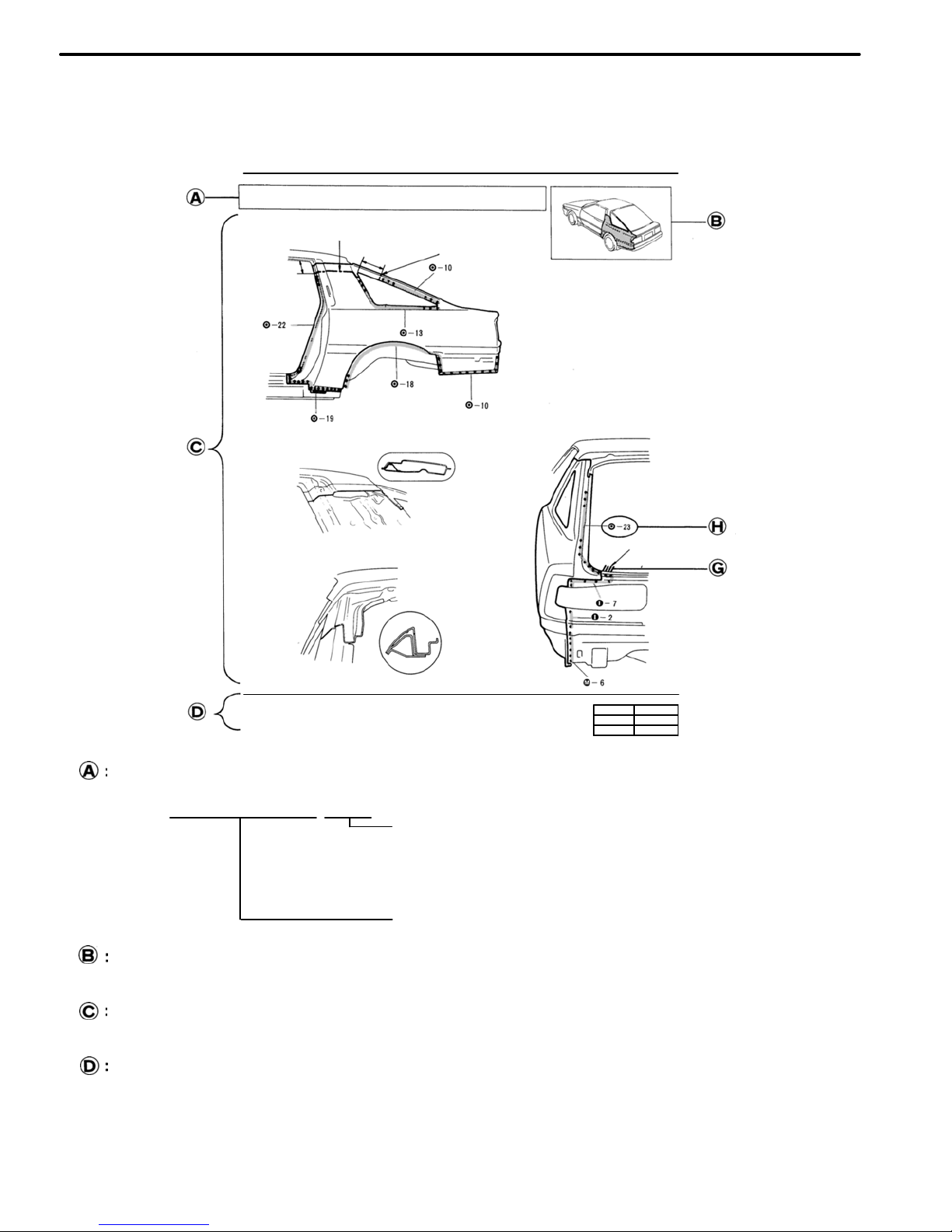
QUARTER PANEL
Cut and Join Location
HOW TO USE THIS MANUAL
Each repair method description provided in Section RE of this manual comprises two pages, divided into
2 blocks (REMOVAL AND INSTALLATION) and includes illustrations to facilitate body repair.
RE−26
BODY PANEL REPLACEMENT−Rear Body Components
QUARTER PANEL (CUT)
REMOVAL
Cut and Join Location
200 mm
80 mm
[Cut and Join Location]
Front
Braze
Rear
1. Cut and join the quarter panel as shown above.
REPLACEMENT PART AND METHOD
(CUT)
Replacement method
(ASSY) Assembly replacement. . . . .
(CUT) Major cutting (less than 1/2 of part used). . . . . .
(CUT−H) Half cutting (about 1/2 of part used). . . .
(CUT−P) Partial cutting (most of part used). . . .
Replacement part
BODY VARIATIONS AND PART LOCATION
Body variations: Non All models. . . .
REMOVAL DIAGRAM
Describes in detail removal of the damaged part involving repair by cutting.
REMOVAL GUIDE
Provides additional information to more efficiently help you perform the removal.
INTRODUCTION
IN-2
mm in.
5
0.20
1. Before temporarily installing the new part, apply
body sealer to the wheel arch portion.
NOTE:
1) Apply sealer approx. 5 mm (0.20 in.) from the
flange, avoiding any oozing.
2) Apply evenly, approx. 3 − 4 mm (0.12 − 0.16 in.)
in diameter.
3) For other sealing points, refer to section SU.
BODY PANEL REPLACEMENT−Rear Body Components
RE−27
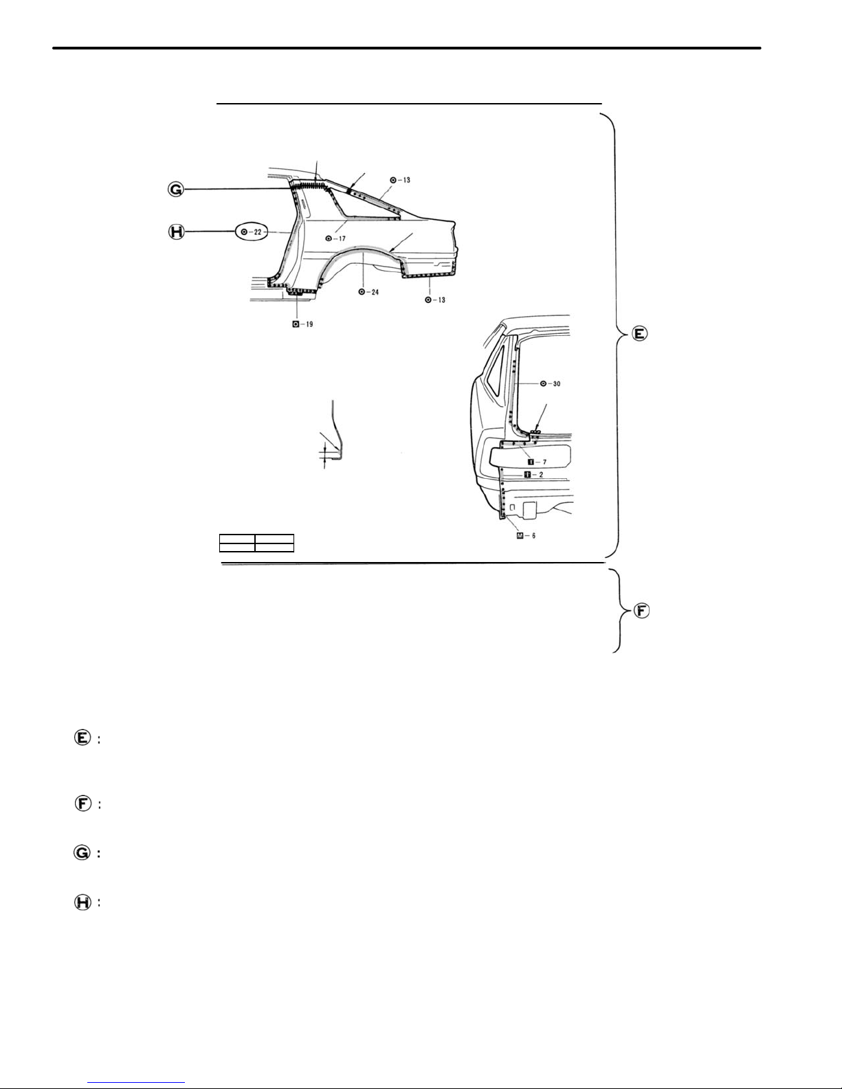
INSTALLATION
Butt Weld
Butt Weld
Body Sealer
Braze
Body Sealer
About 5 mm
2. Temporarily installing the new part and check the fit of
the front door, luggage compartment door and rear
combination lamp.
INSTALLATION DIAGRAM
Describes in detail installation of the new part involving repair by welding and/or cutting, but excluding painting.
INSTALLATION GUIDE
Provides additional information to more efficiently help you perform the installation.
SYMBOLS
See page IN−4.
ILLUSTRATION OF WELD POINT
Weld method and panel position symbols.
See page IN−5.
INTRODUCTION
IN-3
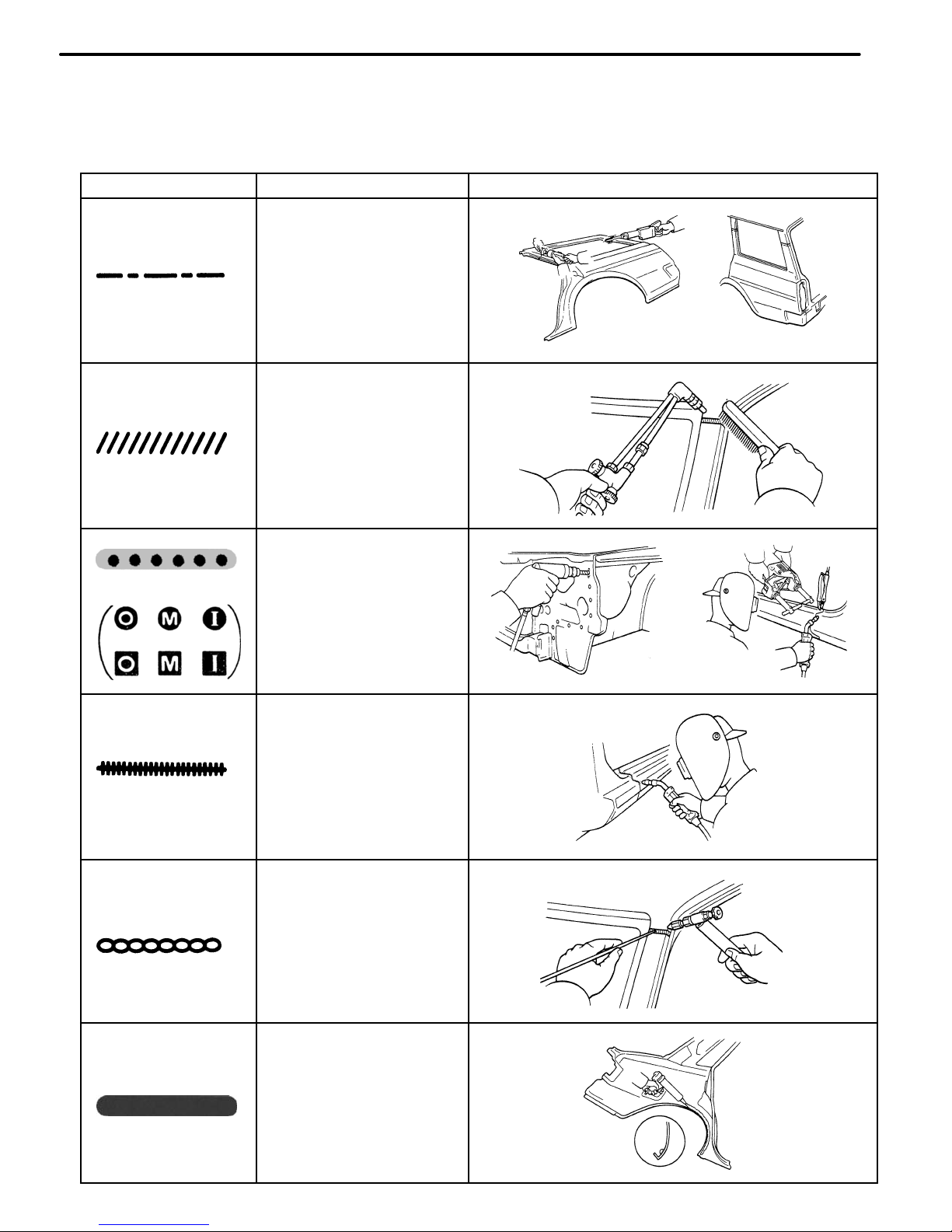
SYMBOLS
MEANING
ILLUSTRATION
SAW CUT OR
ROUGH CUT
REMOVE BRAZE
(See page IN−5)
SPOT WELD OR
MIG PLUG WELD
WELD POINTS
BRAZE
CONTINUOUS MIG
WELD (BUTT WELD
OR TACK WELD)
BODY SEALER
SYMBOLS
The following symbols are used in the welding Diagrams in Section RE of this manual to indicate cutting
areas and the types of weld required.
INTRODUCTION
IN-4
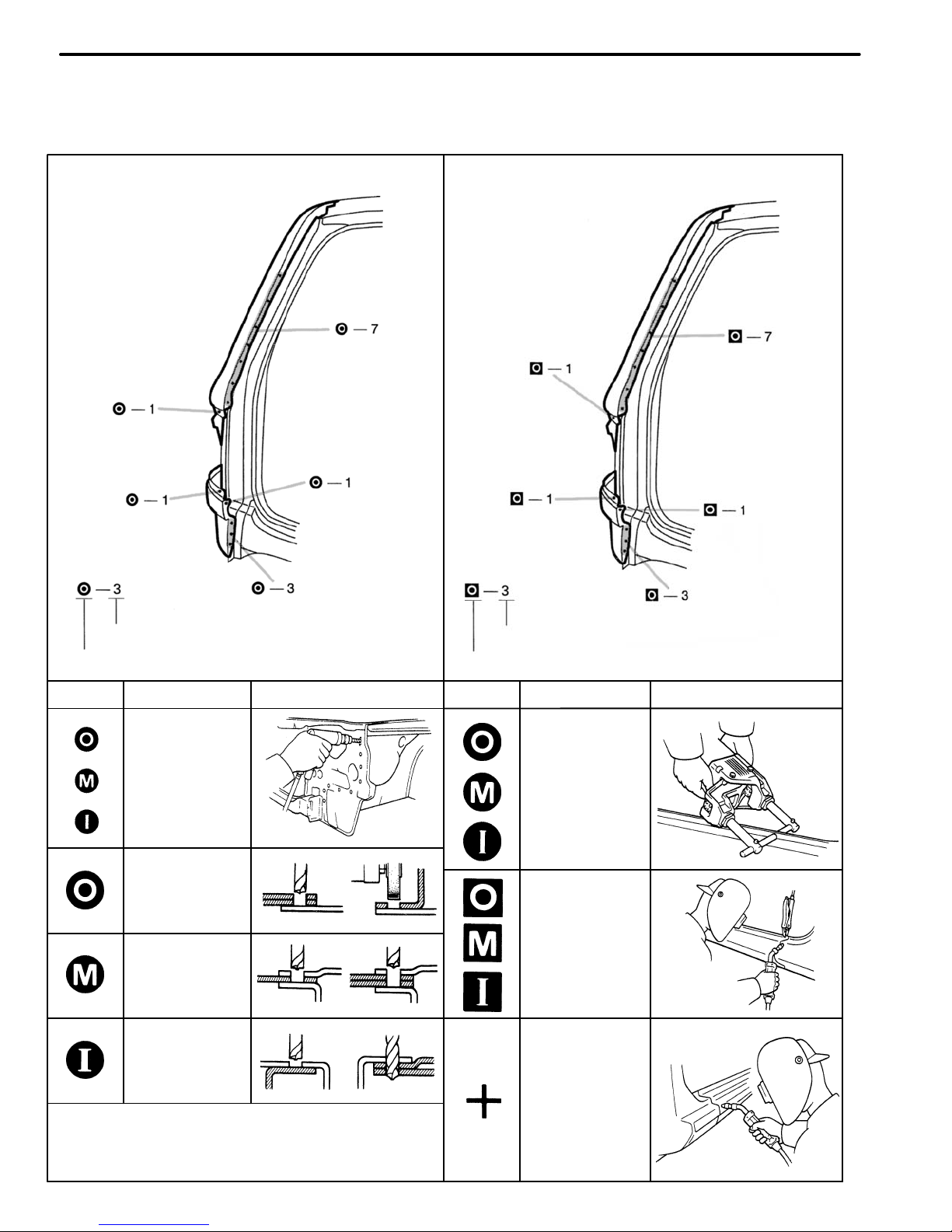
Remove weld point and panel position
Weld points
REMOVAL
Weld method and panel position
Weld points
INSTALLATION
SYMBOL MEANING ILLUSTRATION
SYMBOL
Spot Weld
MEANING
ILLUSTRATION
Remove
Weld
Points
(Outside)
Mig Plug
Weld
(Middle)
(Inside)
Spot MIG
Weld
HINT: Panel position syrnbols are as seen from the
working posture.
Illustration of Weld Point Symbols
EXAMPLE:
INTRODUCTION
IN-5
GENERAL REPAIR INSTRUCTIONS
Work Precautions
SAFETY
1. Before performing repair work, check
for fuel leaks. If a leak is found, be sure
to close the opening totally.
2. If it is necessary to use a frame in the
area of the fuel tank, first remove the
tank and plug the fuel line.
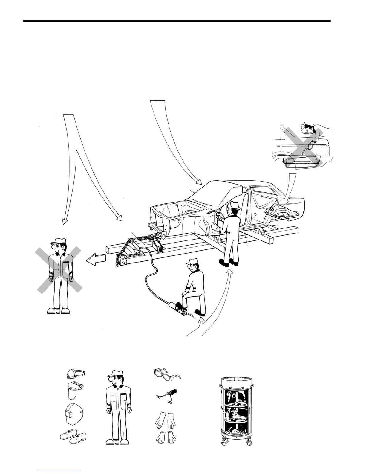
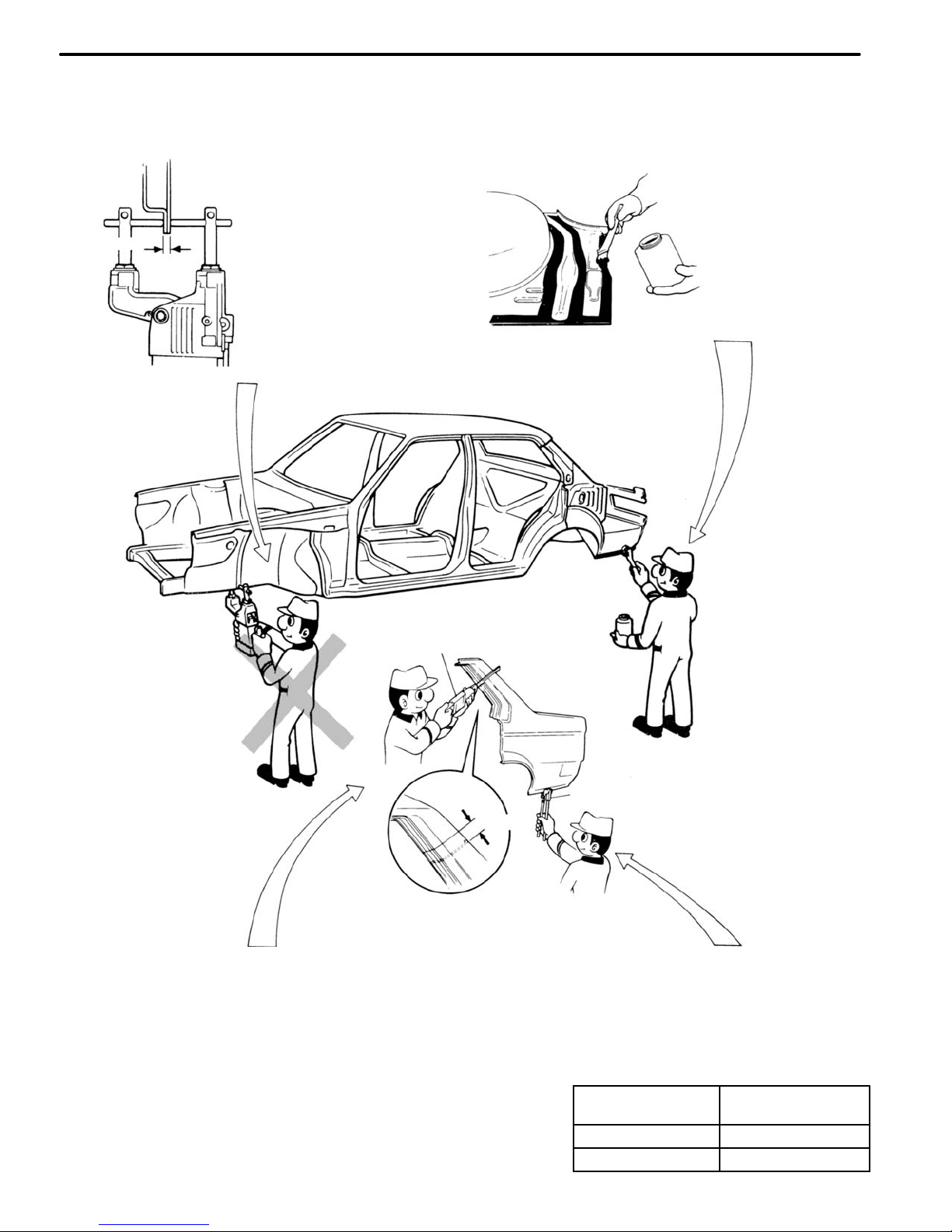
SAFETY
Never stand in direct
line with the chain when
using a puller an the
body or frame, and be
sure to attach a safety
cable.
VEHICLE PROTECTION
When welding, protect the
painted surfaces, windows,
seats and carpet with heat−
resistant, fire−proof covers.
WRONG
Glass Cover
Safety Cable
Seat Cover
WRONG
SAFETY
Before performing repair work,
disconnect the battery cables.
SAFETY WORK CLOTHES
In addition to the usual mechanic wear, cap and Safety shoes,
the necessary gloves, head protector, glasses, ear plugs, face
protector, dust−prevention mask, etc. should be worn as the
situation demands.
Welder’s
Glasses
Body
Mechanic
Stand
Dust−
Prevention
Mask
Face
Protector
Ear
Plugs
Head
Protector Welder’s
Gloves
HAND TOOLS
Keeping your hand tools
in neat order will have
an effect on your work
efficiency.
Safety
Shoes
Cotton
Gloves
INTRODUCTION
IN-6
REMOVAL OF ADJACENT
PART S
When removing adjacent parts
by avoid accidental marring,
etc., wrapping the tools used
and surrounding body parts in
protective tape.
NOTE:
1) Take particular care not
to damage any screw or
clip holes.
2) If you do scratch a
painted surface, retouch
immediatly after. Even a
small scratch will result
in rust and corrosion.
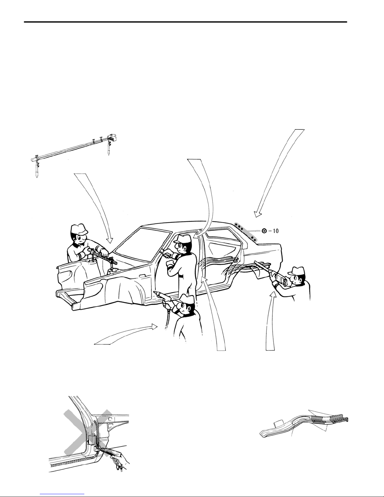
Proper and Efficient Work Procedures
REMOVAL
REMOVAL. OF ADJACENT COMPONENTS
When removing adjacent components, apply
protective tape to the surrounding body and
your tools to prevent damage.
CAUTION:
1. Be especially careful not to damage
screw or clip holes.
2. If the paint is accidently scratched, apply touch−up paint immediately. Even
the slightest scratch may result in corrosion or appearance of rust.
NO. OF SPOT WELDS
Make a note of the
number of spot welds
for later reference.
NOTE: The number
of spot welds may
vary depending on
the vehicle.
PRE−REMOVAL MEASURING
Before removal or cutting operations, take measurements in accordance with the dimension diagram. Always use a puller to
straighten a damaged body or
frame.
CUTTING AREA
Always cut in a straight
line and avoid reinforced
areas.
PRECAUTIONS FOR DRILLING OR
CUTTING
Check behind any area to be drilled or
cut to insure that there are no hoses,
wires, etc., that may be damaged.
Cutting Okay
Corners
Reinforcement
WRONG
INTRODUCTION
IN-7
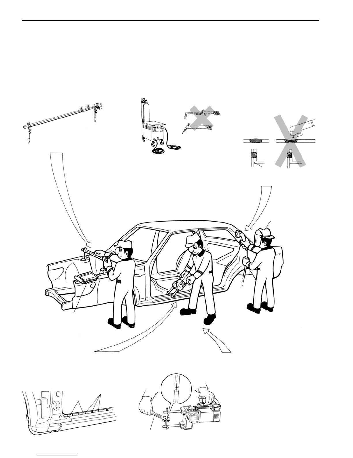
INSTALLATION
WELDING PRECAUTIONS
1. The number of welding spots
should be as follows.
Spot weld: 1.3 x No. of
manufacturer’s spots.
Plug weld: More than No. of
manufacturer’s plugs.
POST−WELDING REFINISHING
1. Always check the welded
spots to insure they are
secure.
2. When smoothing out the
weld spots with a disc
grinder, be careful not to
grind off too much as this
would weaken the weld.
PRE−WELDING MEASUREMENTS
Always take measurements before
installing underbody or engine components to insure correct assembly.
After installation, confirm proper fit.
WRONGOKAY
Seal
OKAY
WRONG
2. Plug welding should be done
with a MIG (Metal Inert Gas)
welder. Do not gas weld or
braze panels at areas other
than specified.
Safety Glass
Body
Measurement
Diagrams
SPOT WELDING PRECAUTIONS
1. The shape of the welding
tip point has an effect on
the strength of the weld.
2. Always insure that the
seams and welding tip are
free of paint.
SPOT WELD LOCATIONS
Try to avoid welding over
previous spots.
Old
Spot
Locations
New Spot
Locations
Tip Cutter
INTRODUCTION
IN-8
Thickness of
welded portion
Size of plug hole
1.0 (0.04) under
5 (0.20)
φ over
1.0 (0.04) over
6.5 (0.26)
φ over
REFERENCE:
mm (in.)
PREPARATION FOR INSTALLATION
SPOT WELD POINTS
APPLICATION OF WELD−THROUGH PRIMER
Less than
3 mm
When welding panels with a
combined thickness of over 3
mm (0.12 in.), use a MIG
(Metal Inert Gas) welder for
plug welding.
NOTE: Spot welding will
not provide sufficient durability for panels over 3 mm
(0.12 in.) thick.
For treatment
against corrosion,
remove the paint
from the portion of
the new part and
body to be welded,
and apply weld−
through primer.
Air Saw
WRONG
20 − 30 mm
Puncher
Overlap
ROUGH CUTTING OF JOINTS
For joint areas, rough
cut the new part, leaving
20 − 30 mm (0.79 − 1.18 in.)
overlap.
MAKING HOLES FOR PLUG WELDING
For areas where a spot welder cannot
he used, use a puncher or drill to make
holes for plug welding.
INTRODUCTION
IN-9
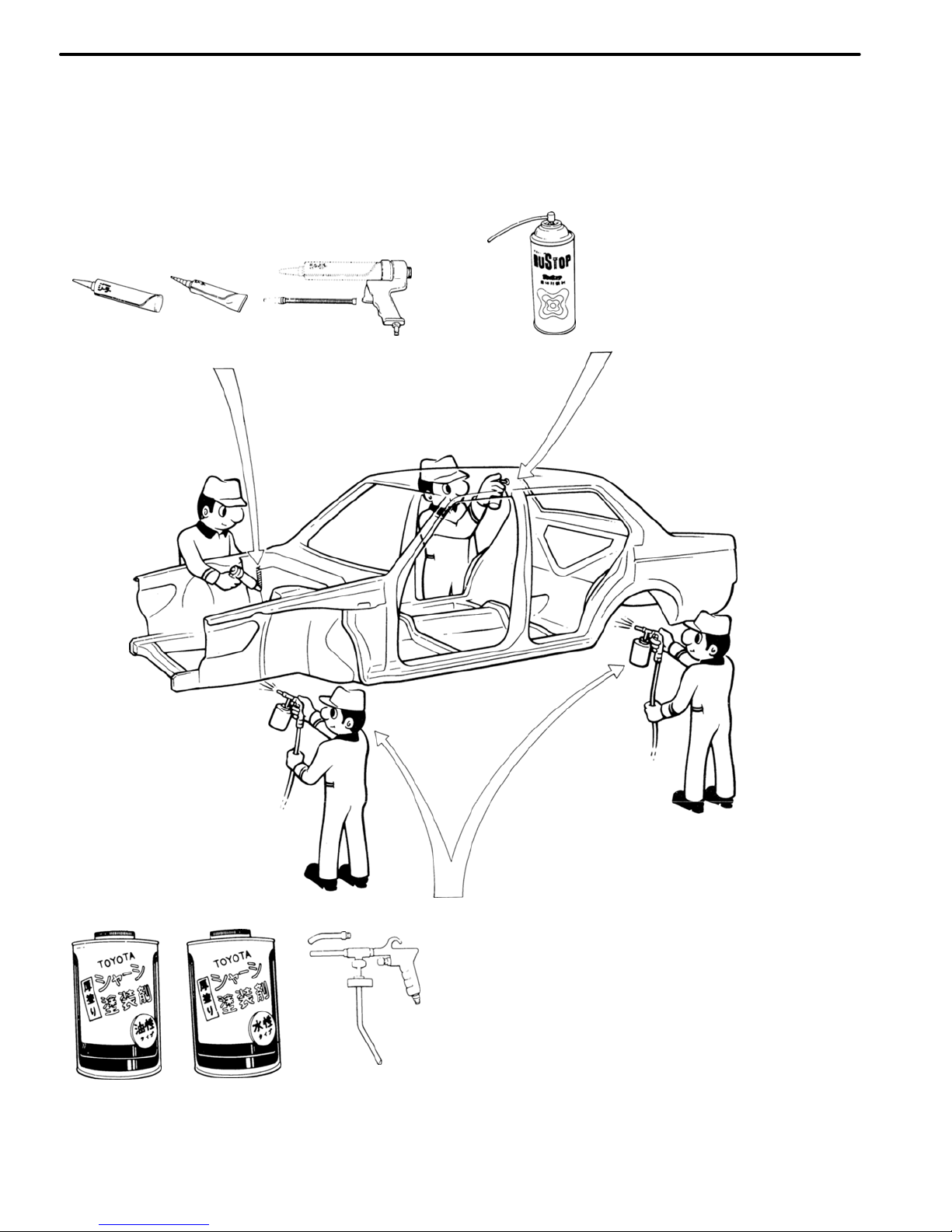
ANTI−CORROSIVE TREATMENT
When replacing body panels, always apply body sealer, anti−rust treatment or undercoating according to
the requirements of your country.
CHASSIS RUST−PROOFING
Anti−rust treatment for welding spots or inside brazed
areas (torque box).
BODY SEALER
Apply body sealer to the
required areas.
Nozzle
Tube
Type
Air Gun
Cartridge
Type
UNDERCOATING
Anti−rust treatment for underbody welding
spots and wheel housings.
Spray Gun
Undercoating
(Water base)
Undercoating
(Oil base)
INTRODUCTION
IN-10
IN0088
IN0089
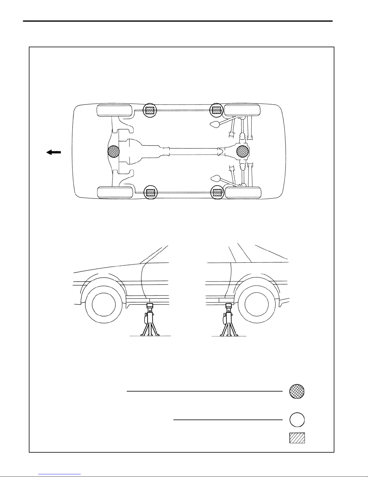
SUPPORT POSITION
PANTOGRAPH JACK POSITION
Front Center of front suspension crossmember. . . . . . . . .
Rear Center of differential carrier. . . . . . . . . .
JACK POSITION
Safety stand . . . . . . . . . . . . . . . . . . . . . . . . . . . . . . . . . . . . . . . . . . . . .
Front
VEHICLE LIFT AND SUPPORT LOCATIONS
INTRODUCTION
IN-11

Assy, assy Assembly, assembly
Sub−assy Sub−assembly
Ex. Except
in. Inch
IRS Independent Rear Suspension
4−link 4−link Rear Suspension
MIG Metal Inert Gas
M/Y Model Year
OPN Operation
SP Spot Weld (Resistance Spot Weld)
w/ With
w/o Without
FR Front
RR Rear
RH Right−hand
RHD Right−hand Drive
LH Left−hand
LHD Left−hand Drive
ABBREVIATIONS USED IN THIS MANUAL
For convenience, the following abbreviations are used in this
manual.
INTRODUCTION
IN-12
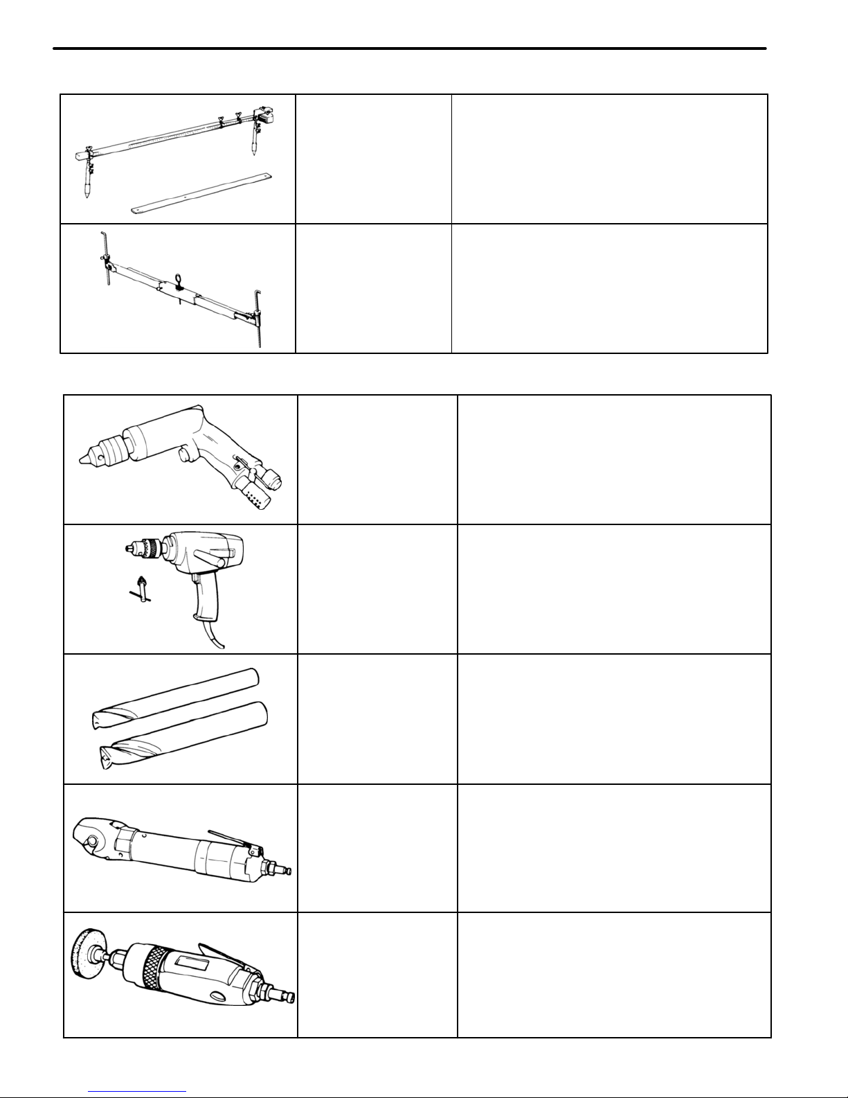
Air−powered
Drill
For separating spot welds and making
holes in the body.
Electric−
powered
Drill
For separating spot welds and making
holes in the body.
Spot Cutter
For separating spot welds.
Air−powered
Cutter
For cutting panels.
Air−powered
Chuck Grinder
For separating spot and plug welds
and grinding off traces of plug welds.
Tracking Gauge
For measuring body dimensions
Frame Centering
Gauge
When 3 or 4 are used together, measurements of twists, bends or warps in the
body and frame are possible.
MEASURING INSTRUMENTS
SEPARATING TOOLS
TOOLS AND EQUIPMENT
TE-2
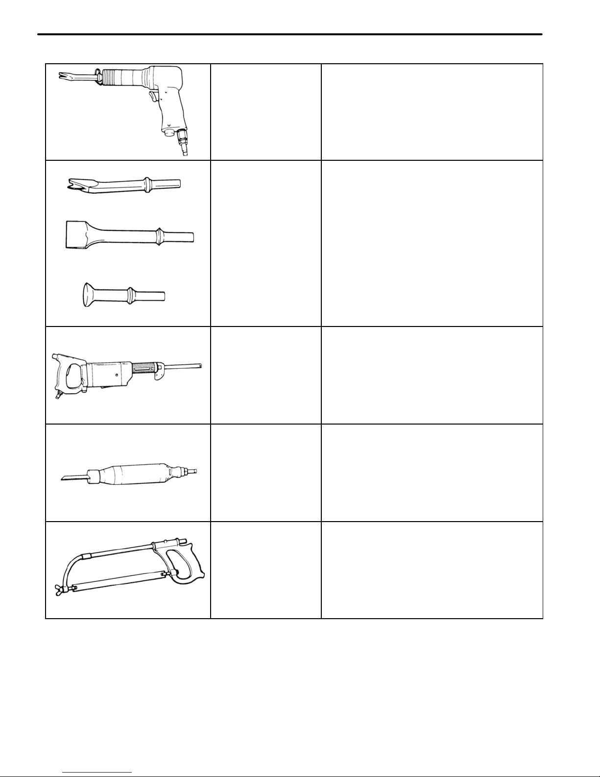
Air−powered
Chisel
For rough cutting and rough flattening
of panels.
Hammer Tool
Flat Chisel
Panel Cutter
For rough flattening in hard−to−reach
areas.
For separating spot welds.
For rough cutting of panels.
Air−powered
Saw
For rough cutting of pillars, rocker
panels, etc.
Air−powered
Saw
For rough cutting of pillars, rocker
panels, etc.
Hacksaw
For rough cutting of pillars, rocker
panels, etc.
SEPARATING TOOLS (Cont’d)
TOOLS AND EQUIPMENT
TE-3
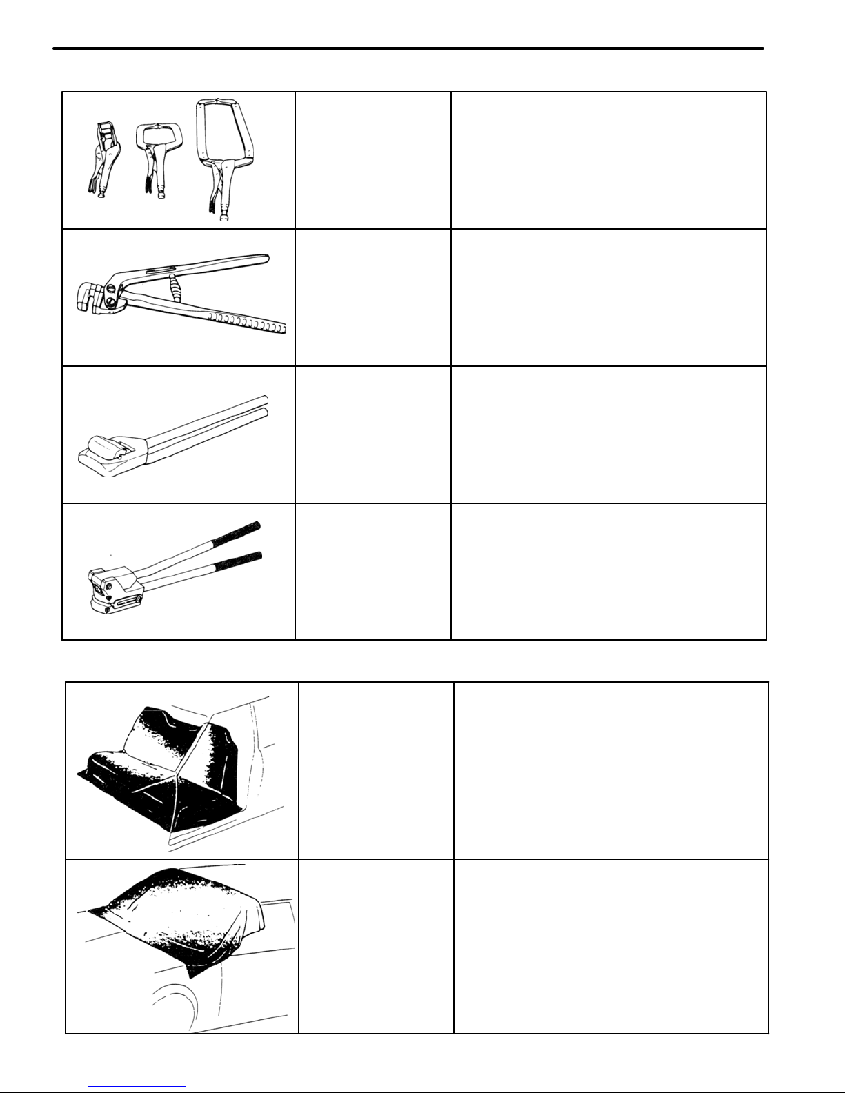
Seat Cover
For protecting the seats from welding
sparks, etc.
Glass Cover
For protecting the glass from welding
sparks, etc.
Vise Grip
Wrench
For temporary installation of panels and
holding of portions to be welded.
Flanging Tool
For making flanges in overlapping
panels.
Hemming Tool
For hemming door outer panels, etc.
Hole Punch
For making holes for MIG plug
welding.
INSTALLATION ASSISTANCE TOOLS
BODY PROTECTORS
TOOLS AND EQUIPMENT
TE-4

MIG Welder
(Metal Inert Gas)
For panel welding.
Spot Welder
For panel welding.
Gas Welder Torch
Gas Cutter Torch
For rough cutting of panels,
members, etc.
Acetylene Gas
Torch
For soldering and peeling of
paint.
Straightening
Machine
For straightening distorted
panels.
Panel
Extractor
For extraction of closed−in
panels.
WELDING INSTRUMENTS
TOOLS AND EQUIPMENT
TE-5
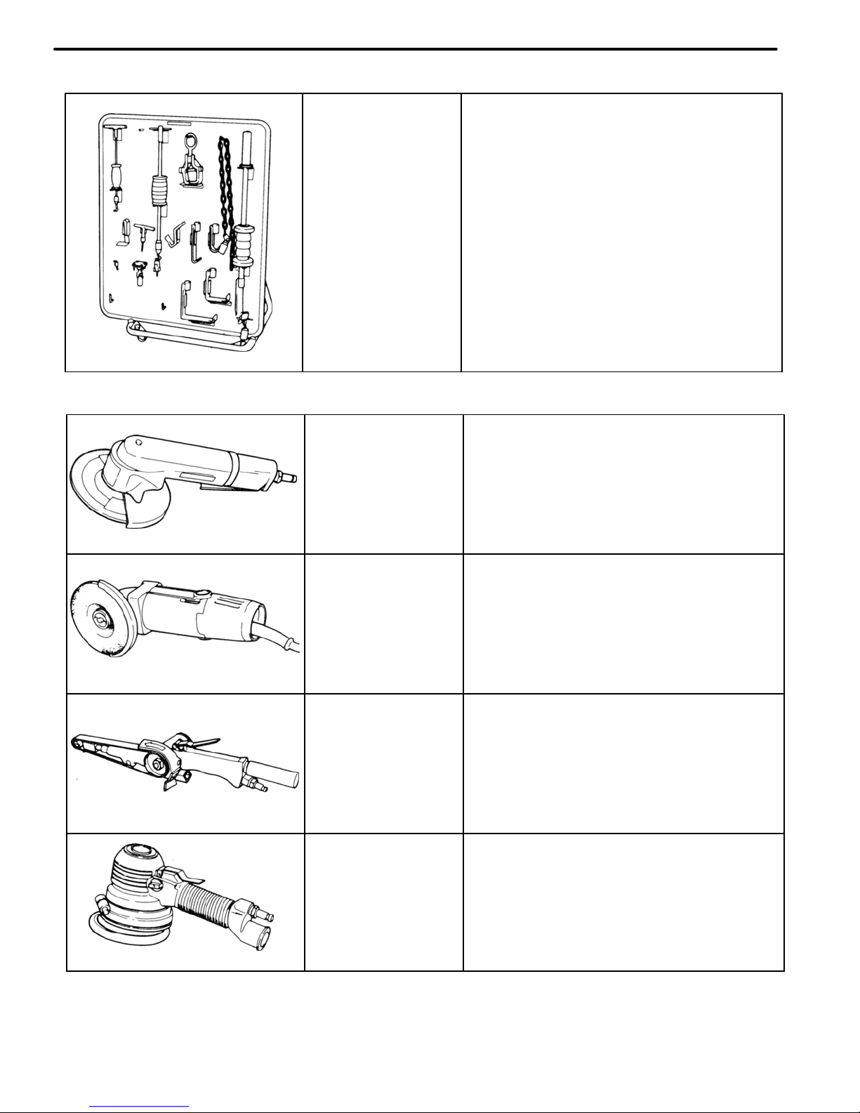
Air−powered
Disc Grinder
For grinding plug welds, butt welds
and door hems.
Electric−
powered
Disc Sander
For grinding plug welds, butt welds
and door hems.
Belt Sander
For removing paint around weld
areas.
Double−action
Sander
For rough grinding and polishing, and
feather edging.
Body Pullers
For straightening lightly
damaged panels.
LIGHT BODY REPAIR TOOLS
GRINDING AND POLISHING TOOLS
TOOLS AND EQUIPMENT
TE-6
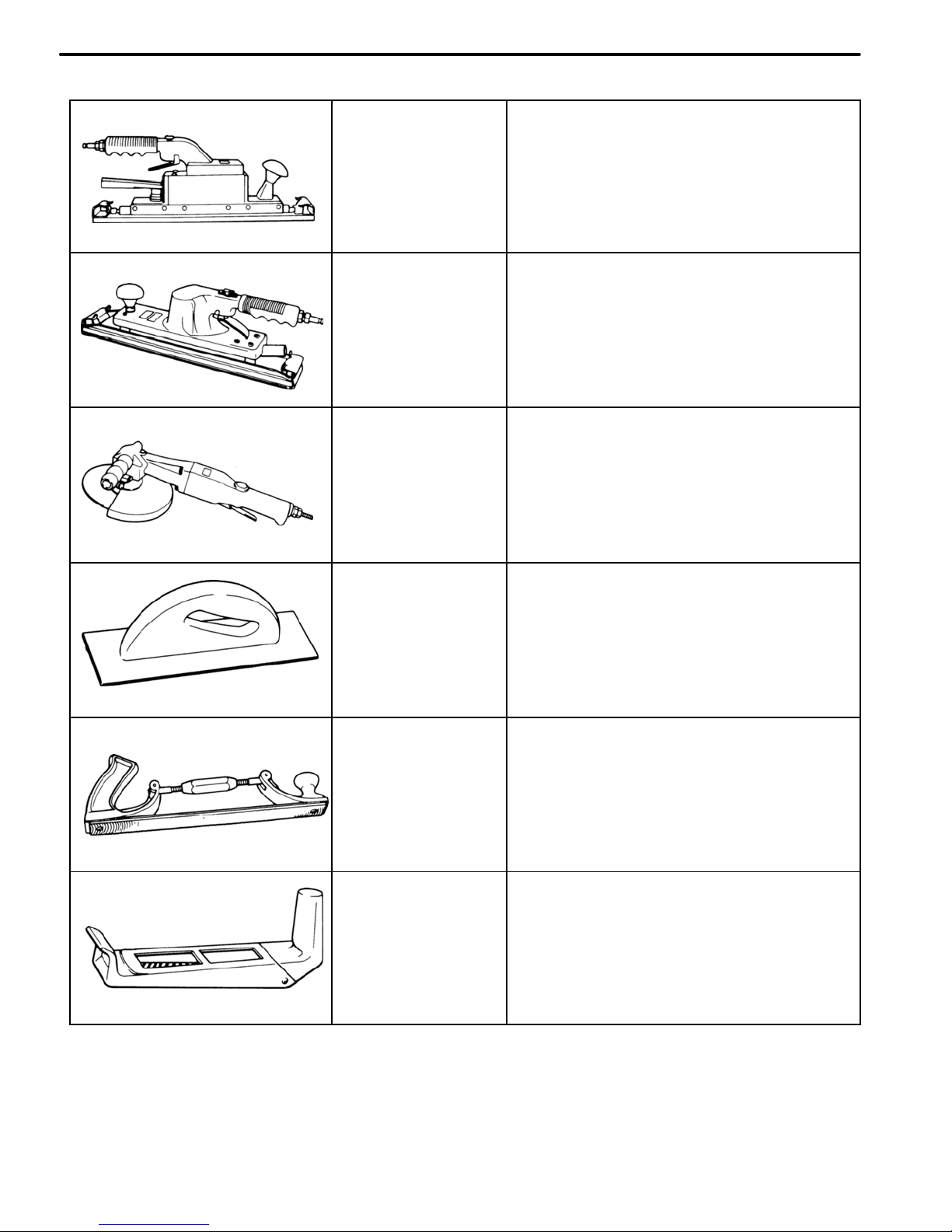
Straight−line
Sander
For rough polishing of panel putty.
Air−powered
Orbital Sander
For removing putty over a wide area, resurfacing and refinishing.
Air−powered
Disc Sander
For peeling paint.
File Holder
For paint removal.
Flexible File
Holder
For correction of soldering spots
and resurfacing of panels.
Surforrn Tool
For rough finishing of panels.
GRINDING AND POLISHING TOOLS (Cont’d)
TOOLS AND EQUIPMENT
TE-7
Master Gauge
Plate Looseness
Two−dimensional
distance
Center−to−center
Horizontal distance in
forward/rearward
Wrong
Correct
GENERAL INFORMATION
1. BASIC DIMENSIONS
(a) There are two types of dimensions in the diagram.
(Three−dimensional distance)
S Straight−line distance between the centers of two
measuring points.
(Two−dimensional distance)
S Horizontal distance in forward/rearward between
the centers of two measuring points.
S The height from an imaginary standard line.
(b) In cases in which only one dimension is given, left
and right are symmetrical.
(c) The dimensions in the following drawing indicate
actual distance. Therefore, please use the dimensions as a reference.
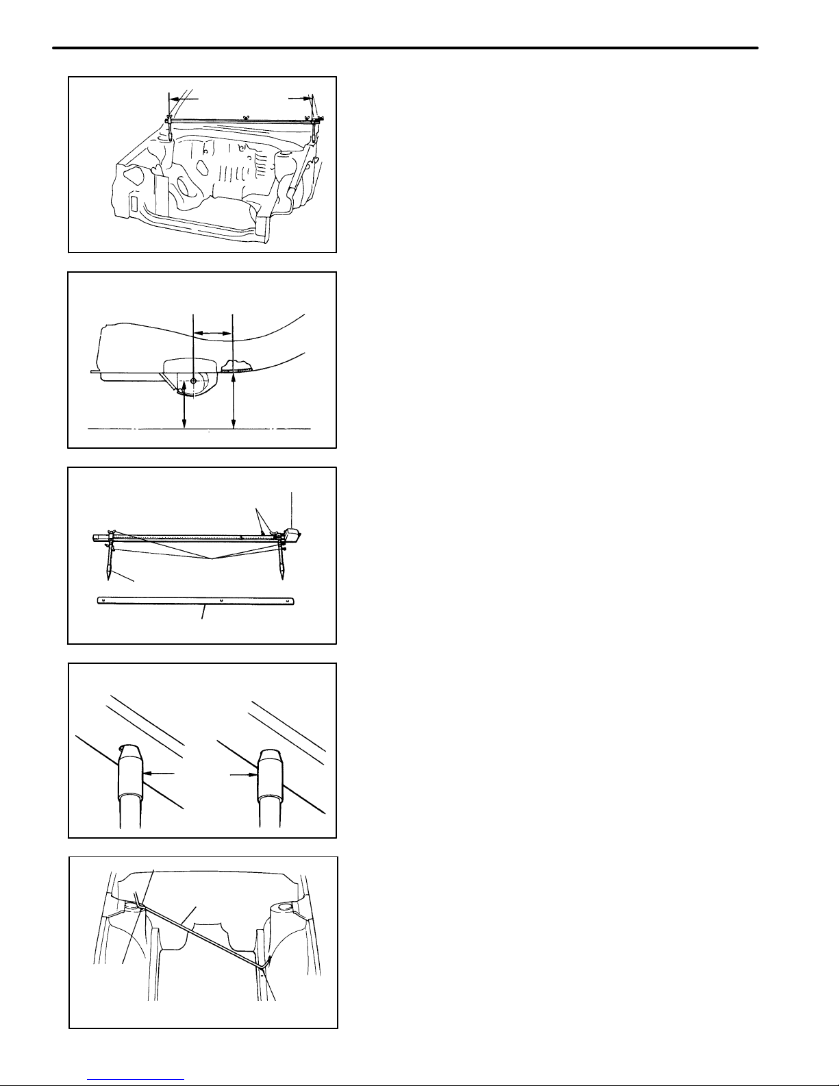
2. MEASURING
(a) Basically, all measurements are to be done with a
tracking gauge. For portions where it is not possible
to use a tracking gauge, a tape measure should be
used.
(b) Use only a tracking gauge that has no looseness in
the body, measuring plate, or pointers.
HINT:
1. The height of the left and right pointers must be equal.
2. Always calibrate the tracking gauge before measuring or
after adjusting the pointer height.
3. Take care not to drop the tracking gauge or otherwise
shock it.
4. Confirm that the pointers are securely in the holes.
(c) When using a tape measure, avoid twists and
bends in the tape.
(d) When tracking a diagonal measurement from the
front spring support inner hole to the suspension
member upper rear installation hole, measure
along the front spring support panel surface.
Pointer
Center−to−center
straight−line
distance
Vertical distance
in lower surface
Vertical distance
in center
Body Looseness
Pointer
Pointer Looseness
Three−dimensional
distance
Imaginary Standard Line
Front Suspension Member Rear Side
Upper Installation Hole
Along Body
Surface
Front Spring Support Inner Hole
Tape Measure
BODY DIMENSIONS
DI-2
mm (in.)
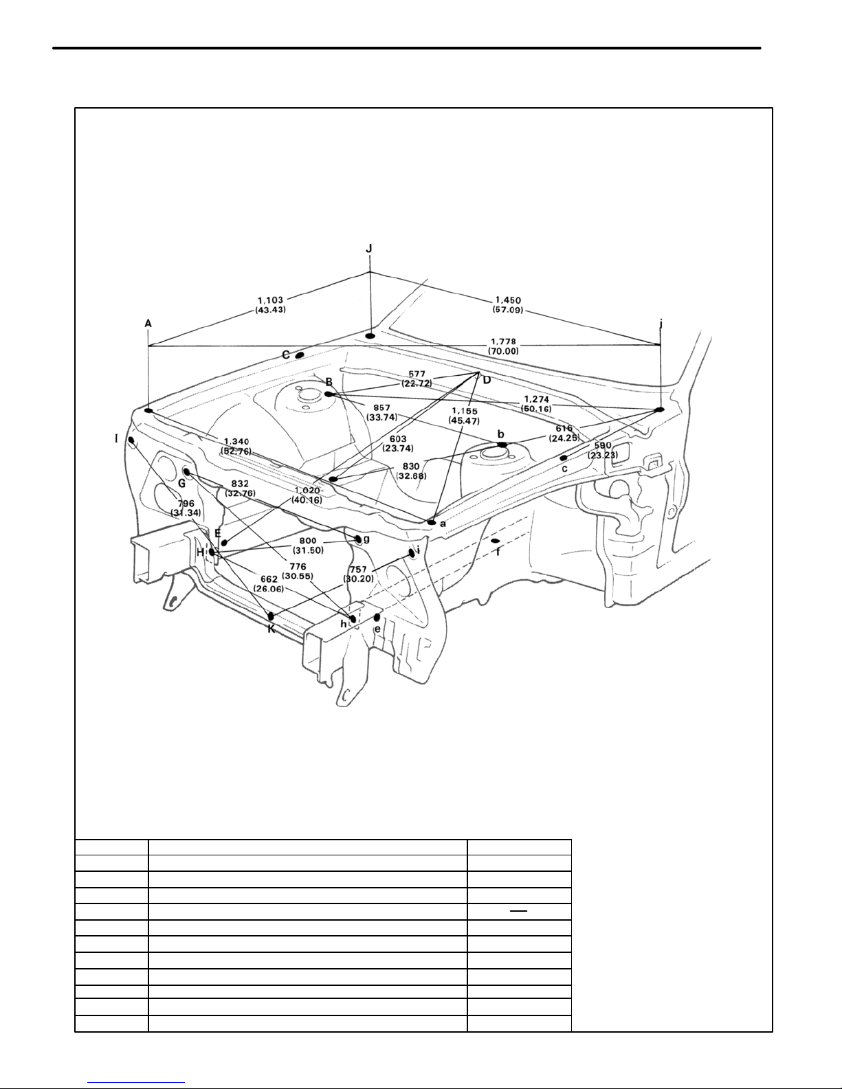
ENGINE COMPARTMENT
Symbol
Nomenclature
Hole dia.
BO1788
A, a
Front fender installation nut−front
8 (0.31)
B, b
Front spring support hole−rear
11 (0.43)
C, c
Front fender installation nut−rear
8 (0.31)
D
Cowl top panel center mark
E, e
Front side member standard hole
15 (0.59)
F, f Suspension member rear installation hole−upper
17 (0.67)
G, g Retractable light bracket installation nut−upper
11 (0.43)
H, h
Radiator seal installation hole−lower
7 (0.28)
I, i Front fonder aide installation hole 8 (0.31)
J, j
Cowl top panel standard hole
10 (0.39)
K
Hood lock support brace installation nut 7 (0.28)
BODY DIMENSION DRAWINGS
BODY DIMENSIONS
DI-3
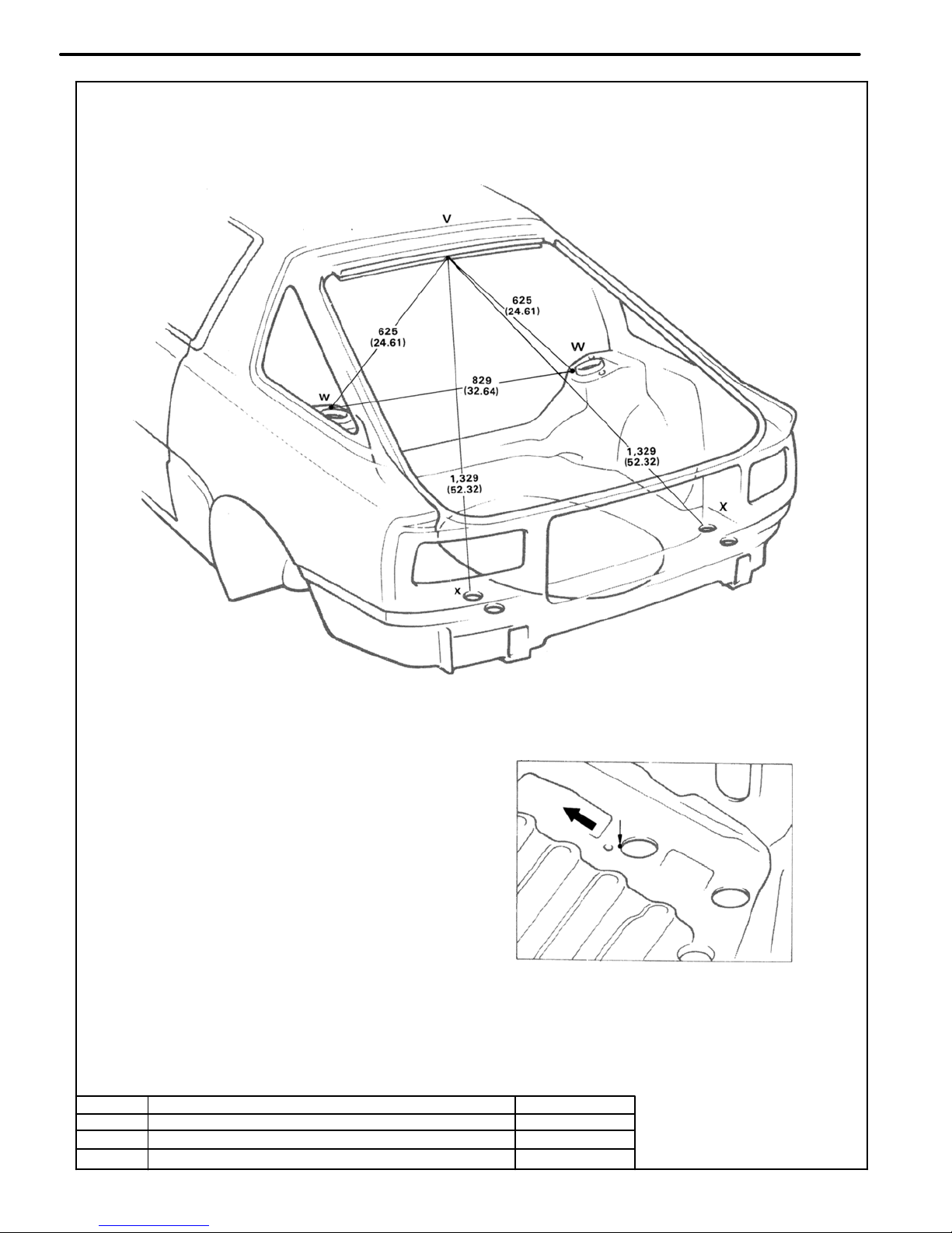
mm (in.)
Front
X, x Point
LUGGAGE COMPARTMENT
Symbol
Nomenclature
Hole dia.
BO1790
V
Back door opening frame center mark
2 (0.08)
W, w
Rear suspension spring support hole−inner
9 (0.35)
X, x
Rear floor pan bumper installation hole−front
40 (1.57)
BODY DIMENSIONS
DI-3
BO1789
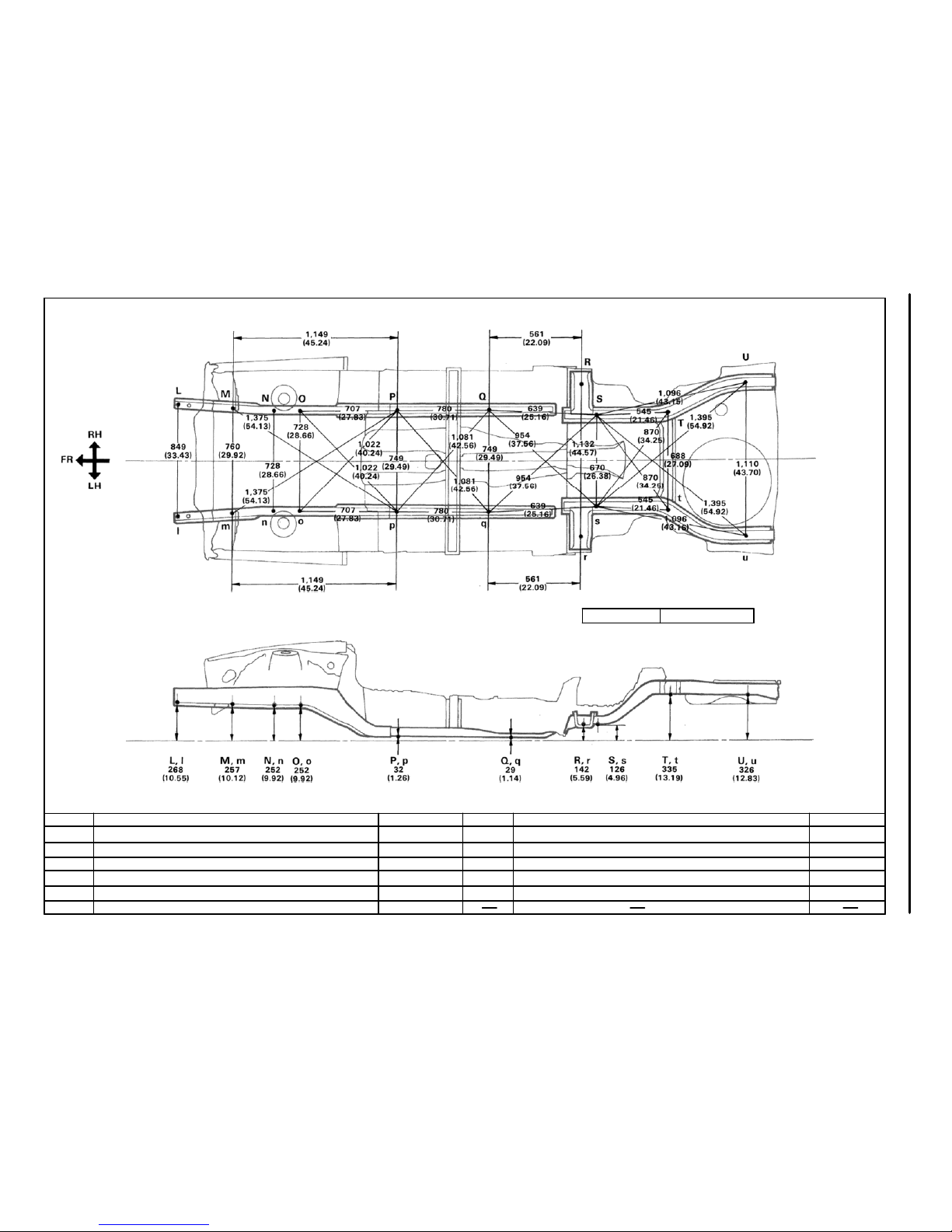
Wheel base 2,595 (102.17)
Imaginary
Standard
line
UNDER BODY
mm (in)
Hole dia.
10 (0.39)
19 (0.75)
18 (0.71)
25×18(0.98×0.71)
18 (0.71)
Nomenclature
Front floor No. 2 reinforcement standard hole
Suspension member front installation hole−outer
Center floor side member standard hole
Suspension member rear installation hole
Rear floor side member standard hole
Symbol
Q,q
R, r
S, s
T, t
U, u
Hole dia
15 (0.59)
17×15 (0.67×0.59)
11 (0.43)
17 (0.67)
17 (0.67)
10 (0.39)
Nomenclature
Front side member bumper front installation hole−Lower
Front side member bumper front installation hole−Lower
Stabilizer front installation nut
Suspension member front installation hole−lower
Suspension member rear installation hole−lower
Front floor under reinforcement standard hole
Symbol
L
I
M, m
N, n
O,o
P, p
BODY DIMENSIONS
DI-3
mm in.
2
0.08
7
0.28
10
φ
0.39
l0
φ
l0φ
l0φ
2R
Center Mark
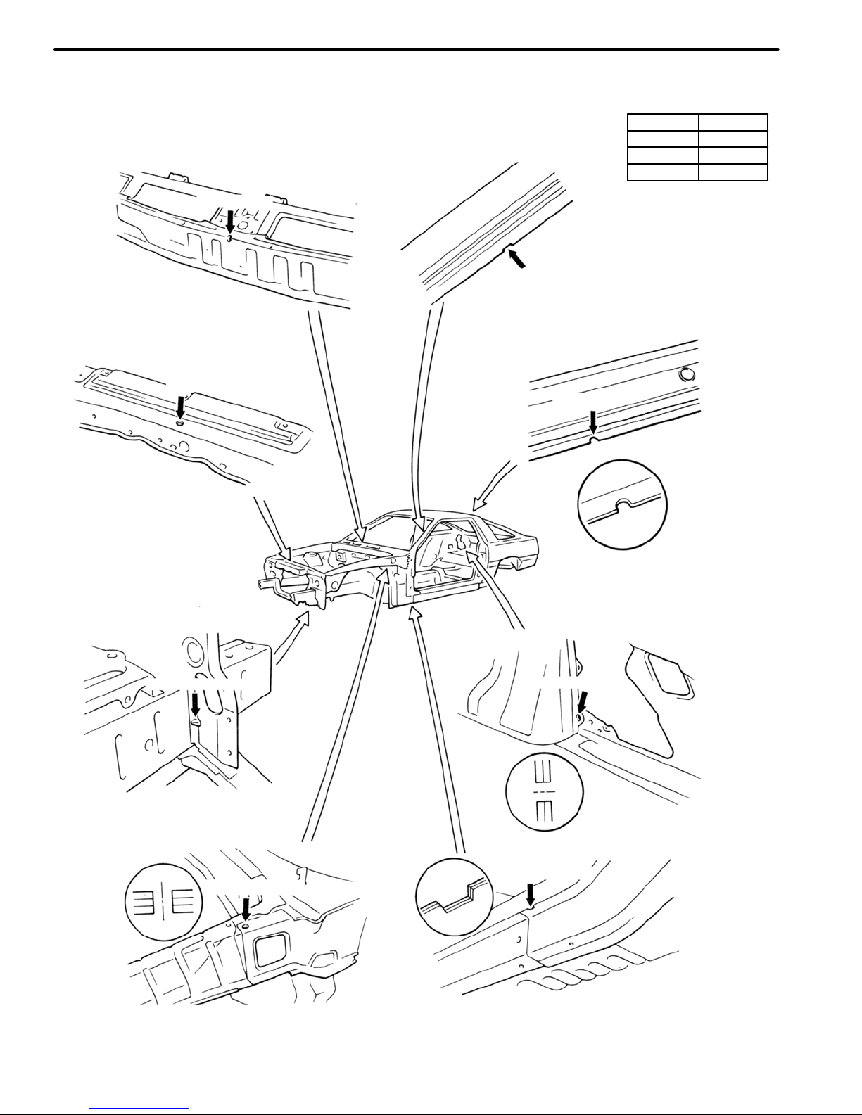
STANDARD BODY MARKS
LIFTBACK
Assembly Mark
Center Mark
(7
φ)
Center Mark
Assembly MarkAssembly Mark
Assembly Mark
Assembly Mark
l0
φ
BODY PANEL CONSTRUCTION
CN-2
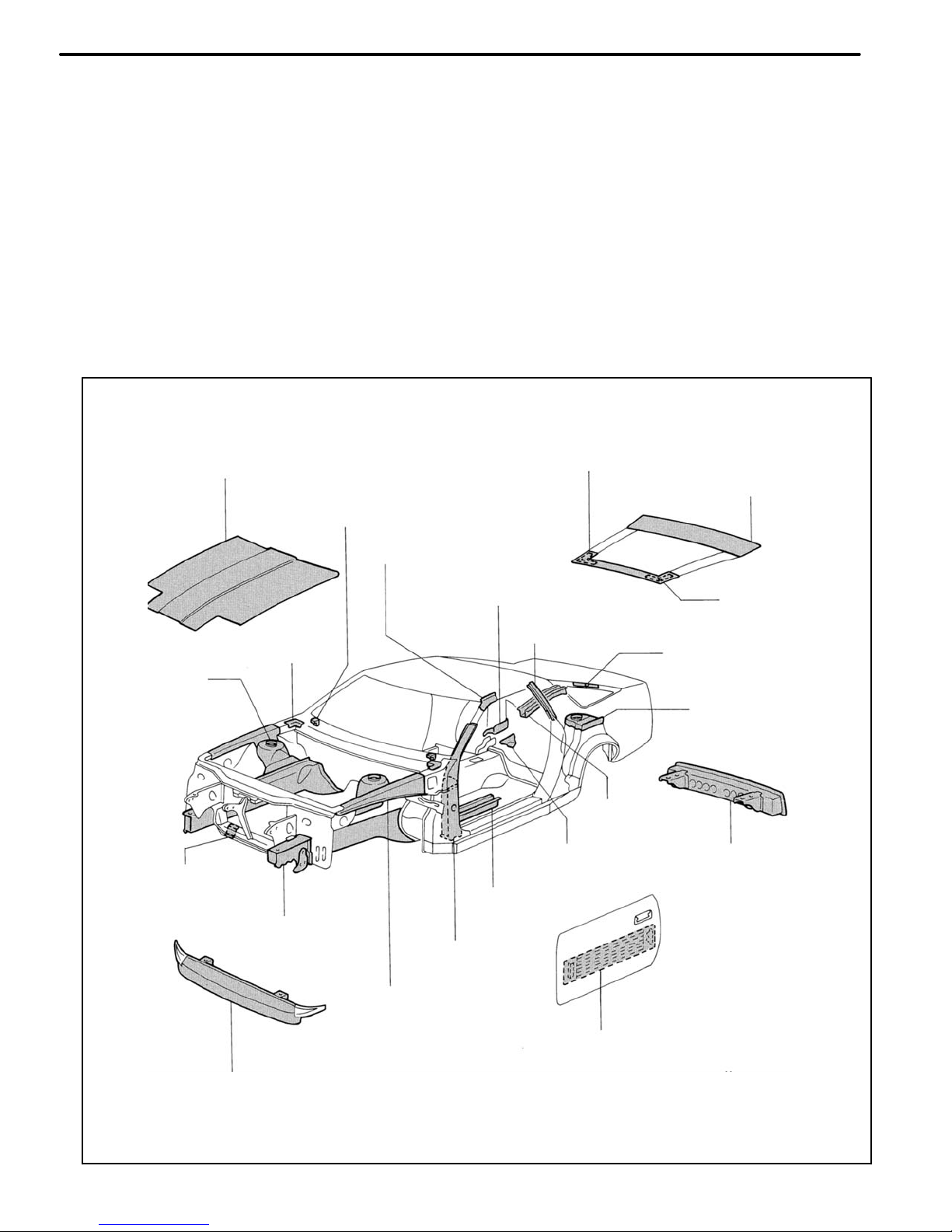
Door Side Impact
Protection Beam
(USA, Canada, Saudi Arabia and
Australia)
Front Bumper Reinforcement
Front Apron to Cowl
Side Upper Member
Front Body
Outer Pillar
Front side Member
Front Floor Under
Reinforcement
Front Crossmember
No. 2 Reinforcement
Rear Bumper
Reinforcement
Belt Anchor
Reinforcement
Rear Floor
Side Member
Rear Suspension
Spring Support
Front Spring
Support Plate
Belt Anchor to Roof
Side Inner Reinforcement
Cowl Top to
Apron Brace
Quarter Pillar Inner
Reinforcement
Back Door Hinge
Reinforcement
Quarter Wheel
Housing No. 1 Gusset
Front Body Pillar Upper
Inner Reinforcement
Hood Stopper
Reinforcement
Back Door Lower
Outer Panel
Engine Hood Panel
Back Door Upper
Outer Panel
The handling of HSS is the same as for mild steel, but the following should be observed.
HIGH−STRENGTH STEEL (HSS) PARTS
Generally, High−Strength Steel (HSS) is that which has an intensity value of at least 35 kg f/mm2, and
distinguished from mild steel.
1. Panel Hammering; Because HSS is thinner than mild steel, care should be taken to avoid warping
during hammering operations.
2. Removing Stop Welds: Because HSS is tougher than mild steel, damage will occur more easily to a
regular drill. Therefore, an HSS Spot Cutter is recommended.
Also, use a high−torque drill at low speed, and supply grinding oil to the drill during use.
3. Panel Welding: Panel welding procedures for HSS are exactly the same as for mild steel. Plug
welding should be done with a MIG (Metal Inert Gas) welder. Do not gas weld or braze panels at
areas other than specified.
BODY PANEL CONSTRUCTION
CN-3
 Loading...