


A
INTRODUCTION
This manual consists of the following 11 sections:
N
o
.
Section
Description
A
B
C
D
E
F
INDEX
I
NTRODUCTION
HOW TO U
TH
IS MANUAL
TROU
SHOOTING
ABBREVIATIONS
GLOSSARY O
TERM
SYMBOLS
R
ELAY LOCATIONS
BLE
S A
SE
-
F
ND
Index of the contents of this m
Brief explanation of each section.
Instructions on how to use this m
Describes the basic inspection procedures for electrical circuits
Defines
Defines
Shows
This section is closely rel
the abbreviations us
the symbols and functions of major parts.
positi
on of the Electronic C
anual.
anual.
ed in this m
ontrol Unit, Relays, Relay Block, etc.
ated to the
anual.
system circui
t.
.
G
H
I
J
K
ELE
CTRIC
WIRING ROUTIN
POWER SO
(Curr
INDEX
SYSTEM CI
GRO
OVERALL
ELE
CTRIC
WIRING D
AL
URC
ent Flow Chart
RCUIT
UND POINTS
AL
IAGRA
G
E
)
S
M
Describes positi
This section is closely rel
Describes power distri
l
oads.
Index of the
Electrical circuits
ground points.
classifi
secti
T
also c
Shows gr
Provides circui
ed by code according to the connection method. (Refer to the
on, “How to use this m
he “System Outline” and “Service Hints” useful for troubleshooting are
ontained in this secti
ound positions
on of Parts Connectors
ated to the
bution from the power supply
system circuits
of each
Wiri
ng connections and their positions are show
t diagrams showi
.
system are show
anua
on.
of all the parts descri
, Splic
system circui
l”)
.
ng the circuit connections.
e points, Ground points, etc.
t.
to various electrical
n from the power supply
bed in this m
through
n and
anual.
2

HOW TO U
SE THIS
MANUAL
B
This manual provides i
by dividing them into a circuit for each
T
he actual
source is received from the battery as
diagrams are shown wi
W
hen troubleshooting any problem, firs
wher
e the problem was detected (s
s
upplying power to that circuit (s
points (s
circui
W
circui
sections
harness and
system circui
unders
Wiri
(from
Wiri
t operation.
hen the circuit operation is
t to isol
ng related to each
,to ). When overall connections are required, see the Overall Electrical
ng Diagram at the end of this m
wiri
ng of each
ee Ground Points section). See the System Outline to unders
ate the cause. Use Relay
to find each part, junction block and
wiri
ng harness connectors, splice points, and ground points of each
t. Internal
tanding of connection within a junction block.
nformation on the electrical circuits install
system circuit is shown from the point where the powe
th the switches i
ee System
ee Power Source section)
unders
wiri
ng for each junction block is also provi
system is indic
tood, begin troubleshooting of the proble
anual.
ed on vehicle
system
far as each ground point. (All circuit
n the OFF
t unders
Location and Electrical Wiri
ated in each
.
positi
tand the operation of the circuit
Circuit section), the power sourc
wiri
ng harness connectors, wiri
on.
)
, and the ground
system circui
tand the
ng Routing
ded for bette
t by arrows
s
r
e
m
ng
r
3

B HOW TO U
SE THIS
MANUAL
* T
he
system show
circuit shown i
n here is
an
n the SYSTEM CI
EXAMPLE ONLY. It is di
RCUIT
S SECTION
.
fferent to the actua
l
4

B
A :System Title
B :
Indic
ates a Relay Block. No shading is us
Relay Block N
Example: 1 Indic
C :
Indic
ates the connector to be connected to a
o. is show
ates Relay Block No. 1.
part (the numeral indic
Explanation of pin use.
T
he pins shown are only
include those in the specification.
D : C
onnector Color Connectors
whi
te in color:
E
: (
) is us
w
ed to indic
hen the vehicle model, engine type, or specification is
ate different
different.
F
:Indic
G :Indic
ates related
ates the
c
onnector. The
shown wi
th arrows (
system
wiri
ng harness and
wiri
n to disti
ates the pin No.
nguish i
)
t from the J/B.
for the highest grade, or only
ed and only
not indic
wiri
ated are
ng and connector, etc.
.
wiri
ng harness with male te
v
).
v
ng harness
milky
rminal is
the
J :Indic
ates the
wiri
ng color.
Wire colors are indic
B
= Bla
ck
BR = Brown
G = Green
GR = Gra
T
he first l
l
etter indic
y
etter indic
ates the color of the stripe.
ated by an alphabetical c
L = Bla
LG = Light Green
O = Orange
P = Pin
ates the basic
Example: L - Y
(blue)
K :
Indic
ates a
wiri
ng Splic
e Point (Codes are “E” fo
the Engine Room, “I” for the Instrument Panel,
T
he Location of Splic
secti
L :
Page No.
M :
Indic
ates a shielded cable.
on.
e Point I 5 is indicated by the shaded
ck
k
wire color
(yellow)
ode.
R
= Red
V = Violet
W
= White
Y = Yello
w
and the second
r
T
he first l
harness connector(s) indic
“E”
etter of the code for each
wiri
ng harness and
ates thecomponent’s locati
for the Engine Compartment, “I” for the Instrument Panel
and Surrounding area, and “B” for the Body and Surrounding
area.
W
hen more than one code has the firs
comm
on, followed by numbers (
the same type of
H
:Repres
ents a part (all parts are shown in
blue). The code is
parts positi
I :Juncti
on Block (The number in the circle is the
J
/B No. and the connector code is show
it)
. Junction Blo
s
eparate them from other parts .
wiri
ng harness and
the same as the code used in
on.
cks are s
Example:
haded to clearl
3B indicate
that it is inside
Juncti
N
o. 3.
t and second letters i
e.g, IH1, IH2), this indicates
wiri
ng harness connector.
sky
n besi
de
y
s
on Blo
ck
wiri
ng
on, e.g,
N :
Indic
ates a ground point.
T
he first l
the component’s locati
Compartm
etter of the code for each ground point(s) indic
on, e.g. “E” for the Engine
ent, “I” for the Instrument Panel and Surrounding
ate
s
area, and “B” for the Body and Surrounding area.
n
O :Indic
P :W
ates the pin number of the connector.
T
he numbering
c
onnectors
system is different for female and male
.
lower l
lower ri
ght
eft
hen 2 parts both use one connector in common, the part
c
onnector name used in the
s
quare brackets [ ].
wire r
outing section is shown i
s
n
5

B HOW TO U
SE THIS
MANUAL
Q
WITH TH
R
1.
HOLDING MANU
TROL RELAY THROUGH TERMINAL 3 OF THE MASTER SW TERMINAL 2 TO OPERATE A POWER WINDOW CONTROL RELAY. THUS THE
FLOWS FROM TERMINAL
NAL 3
W
(FOR THE “MANU
2.
ONCE THE “AUTO DO
OF THE MASTER SW TERMINAL
THE RELAY
MOTOR CONTINUES THE ROTATION EN
THE WINDOW DESCENDS TO TH
BETWEEN TERMINAL 2 OF THE R
3.
HOLDING THE MANUAL SW
FLOWS TERMINAL 5 OF THE R
STOPS AND CONTINUIN
4. PASSENGER’S WINDOW UP OPERATION (MASTER SW) AND WINDOW LOCK SW
HOLDIN
POWER WINDOW SW (PASSENGER’S)
TERMINAL 1 OF THE MASTER SW TERMINAL 4 TO GRO
STOPPED AND WINDOW CAN STOP AT WILL PLACE. SWITCHING THE WINDOW LOCK SW IN “LOCK” POSITION, THE CIRCUIT
TION
(FOR THE DOWN
R
P 2 POWER WINDOW CONTROL RELA
3-GRO
2-GRO
5-GRO
8-GRO
9-GRO
P 4 POWER WINDOW MASTER S
4-GRO
3-GRO
WINDOW LOCK SW
OPEN WITH THE WINDOW LOCK SW AT LOCK POSITIO
S
SYSTEM OUTLIN
E IGNITION SW T
ELAY AND TERMINAL 8 OF TH
DR
IVER’S WINDOW “MANUAL UP” OPERATION BY MASTER SW
AL SW
T
O GRO
ILL POINT
.
AL DO
DR
IVER’S WINDOW “AUTO DOWN”
TERMINAL 4
DR
IVER’S WINDOW AUTO DOWN RELEA
G PASSENGER’S WINDOW SW (MASTER SW) ON “UP”, THE CURRENT FLOWS FROM TERMINAL 3 OF THE MASTER SW
.
COD
P2 21 P4 21 P6 21
P3 21 P5 21
OPERATION,
SERVICE HINT
UND
: ALWAYS CONTINUIT
UND
: APPROX. 12 VOLTS WITH THE IGNITION SW AT ON POSITIO
UND
: APPROX. 12 VOLTS WITH THE IGNITION SW AT ON POSITION AND THE MASTER SW AT U
UND
: APPROX. 12 VOLTS WITH THE IGNITION SW AT ON POSITION AND THE MASTER SW AT AUTO DOWN POSITIO
UND
: APPROX. 12 VOLTS WITH THE IGNITION SW AT ON POSITION AND THE MASTER SW AT DOWN OR AUTO DOWN POSITIO
UND
: ALWAYS CONTINUIT
UND
: APPROX. 12 VOLTS WITH THE IGNITION SW AT ON POSITIO
:
PARTS LOCATIO
E SEE PAGE
E
URNED ON, THE
E POWER WINDOW SW THROUGH THE DOOR FUSE.
(DR
IVER’S) ON “UP” POSITION LOCATED IN POWER WINDOW MASTER SW, THE CURRENT FLOWS TO TERMINAL
2 OF THE R
UND
. THE MOTOR T
WN”
OPERATION,
WN” BUTTON OF THE MASTER SW
TERMINAL 1 OF TH
(DR
IVER’S) ON “UP” POSITION IN OPERATING AUTO DOWN
ELAY AND RELEASES TH
G ON TO
CURRENT FLOWS IN THE R
S
N
CURRENT FLOWS TO TERMINAL 3 OF TH
ELAY
TERMINAL 1
URNS T
O ASCENT THE WINDOW. RELEASING TH
CURRENT FLOWS IN THE R
OPERATION BY MASTER SW
S 8 AND 9 TO OPERATE THE R
ABLING TO DESCENT THE WINDOW.
E END POSITION. THE CURRENT WILL BE CUT OFF TO R
ELAY AND TERMINAL
SE OPERATION BY MASTER SW
UCHIN
G SW. THE F
TERMINAL 4 TERMINAL
Y
Y
W
Y
TERMINAL 2 OF TH
EVERSE DIRECTION
IS PUSHED, THE CURRENT FLOW TERMINAL
E POWER WINDOW MOTOR
1 IN RELAY.
E AUTO DOWN F
UNCTION SWITCH
N
COD
E SEE PAGE
ELAY. THUS THE
UNCTION IN TH
ES TO MANUAL UP OPERATION.
UND
EVERSE DIRECTION
2 OF THE MOTOR TERMINAL 1
. THE MOTOR RUNS T
N
N
E POWER WINDOW MASTER SW, TERMINAL 2 OF THE POWER WINDOW CONTROL
E POWER WINDOW MOTOR
CURRENT INSIDE TH
TERMINAL 2
. THE CURRENT FROM TERMINAL 3 OF THE MASTER SW
OPERATION
O ASCENT THE WINDOW. RELEASING TH
BECAUSE THE TERMIN
IS SW, THE ROTATION OF MOTOR
BECAUSE THE TERMIN
TERMINAL 1 OF THE R
ELEASE TH
E POWER WINDOW CONTROL RELAY. RELEASING THE HAND FROM SW, WINDO
COD
TERMINAL 1
ALS WHERE IT FLOW ARE CHANGED).
9 OF TH
E POWER WINDOW CONTROL RELAY THROUGH TERMINAL 3
E POWER WINDOW CONTROL RELAY FLOWS FROM TERMINAL 2 O
E AUTO DOWN F
TERMINAL 9 OF TH
ALS WHERE IT FLOWS ARE CHANGED).
P POSITIO
N
E SEE PAGE
UNCTION BASED ON TH
T
: RELAY BLOCK
CODE SEE PAGE
1 16
S
R
ELAY BLOCK (RELAY BLOCK LOCATIO
R
/B NO. 1 (INSTRUMENT PANEL LEFT)
N)
U
:
J
UNCTION BLOCK AND WIRE HARN
COD
E SEE PAGE
38 14
ESS CONNECTOR
J
UNCTION BLOCK AND WIRE HARNESS (CONNECTOR
J
/B NO. 3 AND COWL WIRE (INSTRUMENT PANEL LEFT SIDE
LOCATIO
)
N)
V
: CONNECTOR JOINING WIRE
COD
E SEE PAGE
ID1 26
IH1 26
HARN
ESS
AND WIRE HARN
JOINING WIRE HARN
FRONT DOOR RH WIR
FRONT DOOR LH WIR
ESS
ESS AND WIRE HARNESS (CONNECTOR
E AND COWL WIRE (RIGHT
E AND COWL WIRE (LEFT KICK PANEL
KICK PANEL
LOCATIO
)
)
N)
W
:
GRO
UND
POINT
S
COD
E SEE PAGE GRO
I
C
24
COW
UND
L LE
POINT
FT
LOCATIO
N
X
:
SPLICE POINT
COD
E SEE PAGE
I 5 24
S
WIRE HARN
COWL WIR
ESS WITH
E
SPLICE POINT
S
COD
E SEE PAGE WIRE HARNESS WITH
5 OF TH
E POWER WINDOW CO
TERMINAL 4 OF THE R
IS STOPPED AND THE WINDOWS CAN ST
ELAY
PASSING TERMINAL
E POWER WINDOW SW
IS SW, THE ROTATION OF MOTOR
IS OPENED AND STOPPED THE MOTOR ROTA-
N
CURRENT INSIDE THE R
TERMINAL 3
E I
N
T
O GRO
NCR
EASING
PASSING TERMINAL
6 TO TERMINAL
TERMINAL 7
SPLICE POINT
ELAY
TERMI-
UND
. TH
CURREN
IS
ELAY
OP A
3 OF TH
N-
T
F
E
T
2
W
E
S
6

B
Q :Explains
R :
Indic
S :Indic
Example: Part “P 4” (Power Window Master SW) is
T :
Indic
circui
Example: Connector “1” is
U :
Indic
circui
Example: Connector “3B”c
the
system
ates values or explain the function for reference during troubleshooting.
ates the reference page showing the positi
*The letter in the code is from
parts starting with the letter.
Example: P 4
ates the reference page showing the positi
t.
instrum
ates the reference page showing the positi
t.
and is install
outline.
Part is
Power Window Master S
descri
ent panel.
onnects the Cowl
ed on the instrument panel left si
bed on page 16 on this m
on on the vehicle of the parts in the
on page 21 of the manual.
the first l
4th in orde
Wir
etter of the part, and the number indic
r
W
on on the vehicle of Relay Block Connectors i
anual and is install
on on the vehicle of J/B and
e and J/B No. 3. It is
de.
descri
ed on the left si
Wire Harness i
bed on page 14 of this m
system circui
ates its order in
n the
de of the
n the
t.
system
system
anual,
V :Indic
W :
X :Indic
ates the reference page describing
harness is show
Example: Connector “ID1”c
Indic
ates the reference page showing the positi
Example: Ground point “IC” is
ates the reference page showing the positi
Example: Splic
HINTS
:
n firs
on page 26 of this m
e point “I 5” is
the
wiri
t, followed by the male wiri
onnects the front door RH
anual, and is install
descri
on the Cowl
bed on page 24 of this m
Wire Harness
ng harness and
ng harness)
wire (female)
ed on the right si
on of the ground points on the vehicle.
on of the splic
and is
Juncti
on connector (c
include a short te
number of
tion with the short te
li
ng the
nected to any positi
grouping. Accordingly, i
positi
on in the short te
a
wir
e harness from a different part.
Wir
e harness sharing the same short te
grouping have the same color.
wiri
ng harness connector (the female
.
and cowl
de kick panel.
anual and is install
e points on the vehicle.
descri
wir
wir
e harnesses, the harnesses can be con
bed on page 24 of this m
rminal which is c
e harnesses. Always perform inspec-
rminal install
wire (male)
ed on the cowl left si
ode: J1 to J19) in this m
ed. (When insta
on within the short te
n other vehicles, the same
rminal may
be connected to
. It is
descri
anual.
anua
onnected to a
rminal
)
rminal
l-
l
-
wiri
bed
de.
ng
7

B HOW TO U
T
he “Current Flow Chart” section, describes which parts each power source (fuses
breakers) transmits curr
s
upplied to each
source
system mus
SE THIS
ent to. In the Power
system ar
t be fully
MANUAL
Source circui
e explained. Since all System
unders
tood.
t diagram, the conditions when battery
Circuit diagrams star
t from the power sourc
, fusible links
, and circuit
power is
e, the powe
r
H POWER
T
he chart below shows
etc.) and other parts.
T
he next page and following pages shown the parts to whic
SO
URCE (CURRENT FLOW
the route by which curr
ent flows from
CHART)
the battery
h each electrical source outputs current.
to each electrical source (Fusible Link,
Circuit Breaker, Fuse,
8
* T
POWER SO
he
system show
n here is
URC
E
an
EXAMPLE ONLY. It is di
fferent to the actual circuit shown in the SYSTEM CI
RCUIT
S SECTION
.

T
he ground points circuit diagram shows
W
hen troubleshooting a faulty ground point, checki
help you identify the problem ground quickly
show
n below) can als
o be checked this way
the connections from all major parts to the respectiv
. The relationship between ground points ( , and
.
J GROUND POINT
ng the
e ground points.
system circuits which use a common ground ma
EA
IB
I
C
B
y
* T
he
system show
n here is
an
EXAMPLE ONLY. It is di
fferent to the actual circuit shown in the SYSTEM CI
RCUIT
S SECTION
.
9

C TROUBLESH
OOTING
VO
LTA
GE CHE
CK
(a)Es
(b) Usi
tablish c
check
Example:
A B C-
ng a voltmeter, connect the negative l
ground point or negativ
positive lead to the connector or component te
This check can be done with a test light instead of a
voltm
eter.
CONTINUITY
(a)
Disconnect the battery
vol
tage between the check points.
(b) C
ontact the two leads of an ohmmeter to each of the
check
onditions in which vol
point.
Ignition SW on
Ignition SW and SW 1 on
Ignition SW, SW 1 and Relay on (SW2 off
e battery
AND R
point.
ESIS
TANCE CHECK
terminal or wire s
tage is pres
ead to a good
te
rminal
, and the
o there is
ent at the
rminal
no
)
.
10
If the circuit has diodes, revers
again.
W
hen contacting the negative l
and the positive lead to the negative side, there should be
c
ontinuity.
W
hen contacting the two leads in revers
no continuity.
(c) Use the volt/ohmmeter with high impedance (10
minimum)
for troubleshooting of the electrical circui
e the two leads and che
ead to the diode positive si
e, there should be
ck
kΩ/
t.
de
V

C
FINDING A SHORT CI
(a)Remove the blown fuse and disc
fuse.
(b) C
(c)Es
(d) Disconnect and reconnect the connectors while watchi
(e) Fi
CAUTION
onnect a test light in place of the fuse.
tablish c
Example:
A-Ignition SW on
B-Ignition SW and SW 1 on
C -
the test light.
T
he short lies between the connector where the test
li
ght stays lit and the connector where the light goe
out.
nd the exact location of the short by lightly shaking
the problem
:
(a)
Do not open th
absolutely necessary. (If the IC termin
th
e IC may be destroyed by static electricity.
(b)
When
replacing the internal mechanism (ECU part)
the digit
o
r cl
leads from the IC, etc. of the replacement part (spare
part)
al meter, be careful that no part of your
othing co
.
RCUIT
onnect all loads of the
onditions in whic
Ignition SW, SW 1 and Relay on (Connect the
Relay) and SW 2 off (or Disc
wir
e along the body.
e cover or th
mes in c
h the test light comes on.
onnect SW 2
e case of the ECU un
als are
ontact
with the terminals of
)
s
less
touched
)
bod
ng
,
of
y
DISCONNECTION OF MALE AND FEMAL
CONNECTOR
T
o pull apart the connectors
the
wir
e harness.
HINT
: Check to see what ki
disc
onnecting before pu
S
, pull on the connector itself, not
nd of connector you are
lli
ng apart.
E
11

C TROUBLESH
OOTING
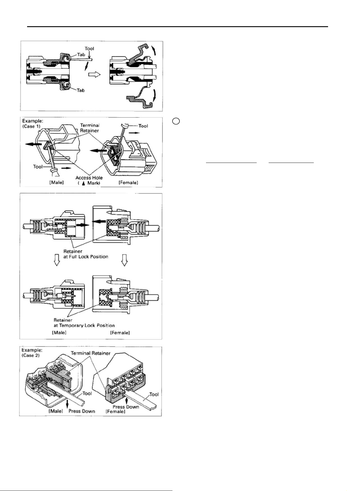
HOW TO REPLACE TERMINAL
(with terminal retainer or sec
ond
ary locking device
)
1.PR
2.DISCONNECT CONNECTO
3.DISENGAGE THE SECONDARY LOCKING DEVICE O
EPARE THE SPECIAL TOOL
HINT:To remov
construc
on the left.
TERMIN
(a)
(b) Use a special
NOTICE:
Do not
A
AL RETAINE
Locki
locking clip c
from the connector.
sec
remo
For Non-W
HINT:T
e the te
t and use the special
ng device must be dis
ondary locking device or te
ve the terminal retainer from c
aterproof Ty
he needle insertion positi
the connector’s s
etc.), so check the positi
rminal from
R
an be released and the te
tool or the te
the connector, please
tool or lik
R
engaged before the te
rminal pick to unlock the
rminal r
pe Connecto
hape (number of te
r
on varies according to
on before inserting it.
e object shown
rminal remov
etainer.
onnector bod
rminal
R
rminal
ed
y.
s
12
“Cas
“Cas
e 1
”
Raise the te
lock
positi
e 2
”
Open the secondary locking device.
rminal r
on.
etainer up to the temporary
B
For W
aterproof Ty
pe Connecto
C
r
HINT:Terminal r
according to connector body.
Example:
Terminal R
Black or White :Gray
Black or White :Dark Gray
Gray or White :Bla
“Cas
e 1
”
Type where te
pulled up to the temporary lock
positi
on (Pull Type)
Insert the special
te
rminal r
and pull the te
the temporary lock
HINT:T
he needle insertion positi
according to the connector’s s
(number
the positi
etainer color is di
etainer :Connector Bod
rminal r
.
tool into the
etainer access hole
rminal r
positi
of te
rminals etc.), so che
on before inserting it.
fferent
ck
etainer is
etainer up to
(Mark)
on.
on varie
hape
y
s
ck
“Cas
e 2
”
Type which c
Power Lock insert the tool straight
i
nto the access hole of te
r
etainer as shown.
annot be pulled as far a
rminal
s
13
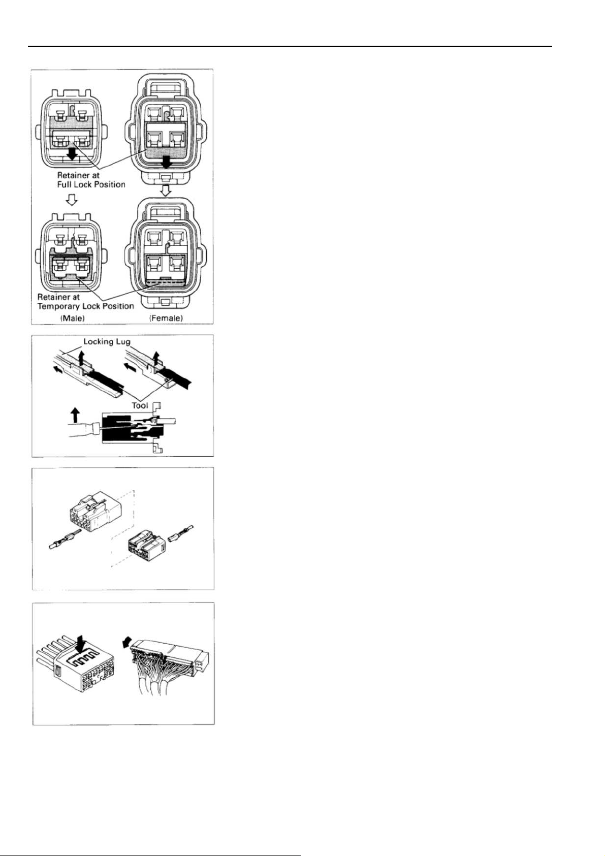
C TROUBLESH
OOTING
Push the te
positi
on.
(
c
) Releas
te
rminal
rminal r
e the locki
out from rear.
etainer down to the temporary lock
ng lug from te
rminal
and pull the
14
4. INSTALL TERMINAL TO CONNECTO
(a)Inser
HINT
1.Make sure the te
2. Insert the te
3. Insert the te
(b)Pus
5. CONNECT CONNECTO
t the terminal
:
temporary lock
h the secondary locking device or te
i
nto the full lock positi
.
rminal is positi
rminal
until the locki
rminal wi
positi
th te
on.
on.
R
rminal r
oned correctly
ng lug lo
etainer in the
R
.
cks firmly.
rminal r
etaine
r

C TRO
UBLESH
OOTING
DISCONNECTION AND CONNECTION OF BOLT
T
YPE CO
For
engine control module in this vehicl
which require a bolt built into the connector to be screw
to securely c
NNECTOR
onnect the connector.
S
e, connections are used
ed down
1.
2.
Disconnect the connecto
After completely looseni
c
onnector can be separated.
NOTICE:
Do not pu
c
onnecto
C
onnect the connecto
NOTICE:
Befo
the terminals are
(a) Matc
(b) Ti
ll the wire harness when disc
r.
re c
onnecting th
h the guide section of the male connecto
correctly with the female connector, then press
them together.
ghten the bolt.
Make sur
c
onnected, by tightening the bolt until there is
clearance of less than 1 mm (0.04 in.) between the
bottom of male connector and the end of female
c
onnector.
e the connectors are compl
r
ng the bolt, the two parts of the
onnecting th
r
e c
onnecto
not bent or d
r, always check tha
amaged.
etely
e
t
r
a
15

ABBREVIATIONS
T
he follow abbreviations ar
e used in this m
anual.
ABBR
EVIATIONS
D
ABS
A/
C
ACIS = Acoustic C
A/
T
COM
B. =Combination SFI = Sequential Multiport Fuel Injection
ECU. = Electronic C
EG
R
ESA = Electronic
EVAP = Evaporativ
J
/B =Junction Blo
L
H
M/T
* The titles giv
as being abbreviations
= Anti-Lock Brake Syste
= Air Conditioning PPS = Progressive Power Steering
ontrol Induction Syste
= Automatic Transmission
ontrol Unit SRS = Supplemental Restraint Syste
= Exhaust Gas Recirculation S
Spark
e Emission
ck
= Left-Hand
=Manual Transmissi
en insi
de the components are the names of the te
.
rm
Advance
on
m R
O/
D
/B =Relay Blo
RH
W
TEM
P. =Temperature
TRAC
VSV = Vacuum Switching Valv
w
/ =With
w
/o =Without
= Overdriv
=Right-Hand
= Switch
=Traction Contro
rminals (te
rminal c
e
ck
odes)
l
and are not treated
m
e
16

E GLOSS
AR
Y OF TERMS AND
BATTER
Y
Stores chemical
converts it i
nto electrical
Provides DC curr
energy and
ent for the
auto’s various electrical circuits.
SY
energy.
MBOL
S
GRO
UND
T
he point at which wiri
to the
Body, thereby providi
r
eturn path for an electrical circui
wi
thout a ground, current cannot
flow.
ng attache
ng a
s
t;
CAPACITOR (Conden
A small
stor
holding unit for temporary
age of electrical vol
ser
)
tage.
CIGARETTE LIGHTER
An electric resis
tance heating
element.
CIRCUIT BREAKER
Basically
breaker
much curr
a reusable fuse, a circuit
will
heat and open if too
ent flows
through it.
Some units automatically reset when
cool
DIOD
A semic
curr
DIOD
, others mus
E
ent flow in only
E, ZENE
A diode whic
t be manually res
onductor whic
one direction.
R
h allows curr
h allows
flow in one direction but blo
reverse flow only
vol
tage. Above that potential, it
up to a specifi
passes the excess voltage.
This acts as a simple vol
r
egulator.
ent
cks
tage
et.
c
HEADLIGHT
1.SINGL
FILAMEN
2.DOUBL
FILAMENT
LIGHT
S
Curr
ent flow causes a headlight
filament to heat up and emit light.
E
T
A headlight may have either a
single (1) filament or a double (2)
filament.
E
HORN
An electric
l
oud audible si
IGNITION COI
device which s
gnal.
L
Convert low-voltage DC current
i
nto high-vol
for f
iri
Curr
ent flow through a filament
causes
the filament to heat up
tage ingition current
ng the spark plugs
and emit light.
ounds a
.
(for Medium Curr
(for Hi
gh Current Fuse o
Fusible Link.
)
PHOTODIODE
DISTRIBUTOR
FU
SE
FUSIBLE LINK
ent Fuse
)
r
T
he photodiode is
semiconductor which c
curr
ent flow according to the
a
ontrols
the
amount of light.
, II
A
C
hannels high-voltage current
from the ignition coil to the
indivi
dual spark plugs
A thin metal strip whic
.
h burn
s
through when too much current
flows
through it, thereby stop
ping current flow and protecting a
circui
t from damage.
A heavyhigh amperage circuits whic
gauge
wir
e placed in
h
burns through on overloads,
thereby protecting the circuit.
T
he numbers indicate the cross
secti
on surface area of the
wires
LED (LIGHT EMITTING DIODE)
U
pon current flow, these diode
emit light without produci
s
ng the
heat of a comparable light.
METER, ANAL
Curr
ent flow activ
OG
ates a magnetic
coil which causes a needle to
mov
FUE
L
e, thereby providi
display
calibrati
METER, D
Curr
many
against a background
on.
IGI
TAL
ent flow activ
LED’s
displays, which provi
or digital display
, L
CD’s, or fluoresent
ng a relativ
ates one o
de a relativ
.
e
r
e
MOTOR
A power unit which converts
M
electrical
energy into mechanical
energy, especially rotary moti
on.
.
17

RELA
Y
1.NO
CLOSE
RMALLY
D
Basically
operated switch which
may
(1) or
, an electricall
be normally closed
open (2). Current
flow through a small
2.NO
OPE
RMALLY
N
coil creates a magnetic
field whic
h either open
or closes
switch.
RELA
Y, DO
UBLE THROW
A relay whic
h passes current
through one set of contacts or the
other.
an attached
E
y
s
SPEAKE
SWI
TCH, MANUAL
1.NORMALLY
2.NO
R
An electromechanical
which cr
curr
eates sound waves fro
ent flow.
O
closes circuits,
OPE
N
thereb
s
allowing (2
RMALLY
CLOSE
D
curr
device
pen and
y
topping (1) o
)
ent flow.
m
r
RESISTO
R
An electrical com
fix
ed resistance, placed in a circuit
ponent with a
to reduce voltage to a specifi
val
ue.
R
ESISTOR, TAPPE
A resistor which s
mor
e different non adjustable
resis
tance values.
R
ESISTOR, VARI
RH
EOS
TAT
D
upplies two o
ABLE o
A controllable resistor with a
variable r
Also call
r
heostat.
SENSOR
ate of resistance.
ed a potentiometer o
(Thermistor
)
A resistor which varies its
resis
tance with temperature.
SENSOR, SPEE
D
Uses magnetic impulses to open
and clos
signal for activati
com
e a switc
ponents.
h to cr
on of othe
r
eate a
SWI
TCH, DOUBLE THROW
A switch which continuousl
c
r
passes cureent through one set of
c
ontacts or the other.
SWI
TCH
,
IGNITIO
N
A key operated switch wi
y
th severa
l
positions which allows various
circuits
, particularly the p
igniti
on circuit, to become
rimar
y
operational.
r
SWI
TCH, W
Automatically returns wipers
the stop positi
switch is
TRAN
SISTO
IPER P
ARK
on when the wipe
turned off.
R
to
r
A solid state device typically used
as an electronic relay; s
r
passes current depending on the
vol
tage applied at “base.
tops o
”
r
18
SHORT PI
SOLENOI
N
Used to provi
c
onnection within a juction block.
de an unbroken
D
An electromagnetic coil which
forms
a magnetic field w
curr
ent flows
, to move a plunger,
etc.
hen
WIR
ES
(1) NOT
CONNECTE
(2)SPLICED
Wires ar
e always
drawn as straight line
on
wiri
D
ng diagrams
Cross
ed
wires (1)
wi
thout a black dot at
the junction are not
joi
ned;
crossed
wires (2)
a black dot o
octagonal
the juction as splic
(joi
ned) connections.
r
(
) mark at
s
.
and
ed

+
F RELAY LOCATION
S
[Engine Compart
me
nt]
[Instru
ment Panel
]
19
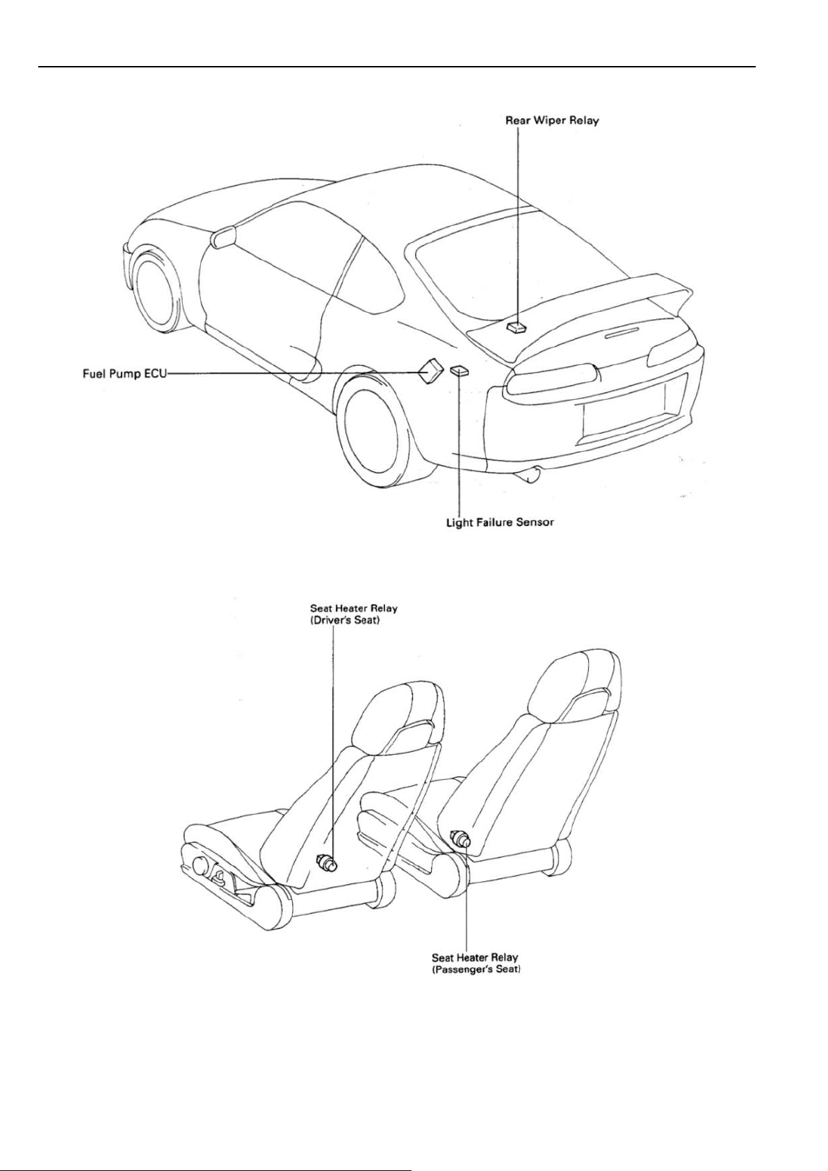
+
[
Body]
F
[
Sea
t]
20

F RELAY LOCATION
:
J/B No
. 1
S
Left K
ick Pan
el (See Page 18
)
21

F
[J/B No. 1 Inner C
ircui
t]
22

F RELAY LOCATION
Engi
f
t (
S
18)
2
: R/B No. 2
:
J/B No. 2
S
n
e Comp
artme
nt Le
ee Page
23

4
: R/B No. 4
Left K
ick Pan
el (See Page 18
F
)
5
: R/B No
. 5 Engine Compartment Right (
See Page 18
)
24

2
6
G ELE
CTRICAL WIRING ROUTIN
G
[2JZ-GTE]
Position of Part
s in Engine Compartme
nt
A 1 A/C Ambient Temp Senso
A 2 A/C Condensor Fan Moto
A 3 A/C
A 4 A/C Magnetic Clutc
A 5 A/T Fluid Temp. Senso
A 6 ABS Actuato
A 7 ABS Actuato
A10 ABS Speed Sensor Front L
A11 ABS Speed Sensor Front
B 1 Back-U
B 2 Brake Fluid Level Warning S
C1Camshaft Positi
C2Camshaft Positi
C3Cranks
C4Cruise Control Actuato
D1D
D2Daytime R
D3Daytime R
E 1 EGR Gas Temp. Senso
E 2 Electronically Controlled Transmissi
E 3 Engine Coolant Temp. Senso
Tripl
e Pressure S
(A/C Dual
ata Link Connector 1
and Single Pressure S
r
r
p Light SW (M/
on Sensor No.1
on Sensor No.2
haft Positi
on Senso
unning Light Relay No.3
unning Light Relay No.3
r
r
W
W)
h and Lock Senso
r
H
RH
T)
W
r
r
r
r
r
on Solenoid
E
4 Engine Coolant Temp. Sende
E 5 Engine Coolant Temp. S
E 6 Engine Hood Courtesy S
E 7 Engine Oil
F3Fr
ont Fog Light L
F4Fr
ont Fog Light
F5Fr
ont Side Marker Li
F6Fr
ont Side Marker Li
F7Fr
ont Turn Signal Light L
F8Fr
ont Turn Signal Light RH and Parking Light
F9Fr
ont Wiper Moto
G 1 Generato
G 2 Generato
H1H
eadlight Hi L
H2H
eadlight Hi
H3H
eadlight Lo L
H4H
eadlight Lo
H5H
eated Oxygen Sensor (Bank 1 Sensor 1
H8Hor
H9Horn RH
n L
Level Senso
H
RH
ght L
ght
r
r
r
H
RH
H
RH
H
r
W
W
r
H
RH
H
RH
)
24

G
[2JZ
Position of Part
s in Engine Compartme
nt
I 1 Idle AIr Control Valv
I 2 Ignite
I 3 Ignite
I 6 Ignition Coil No.1
I 7 Ignition Coil No.2
I 8 Ignition Coil No.3
I 9 Ignition Coil No.4
I10 Ignition Coil No.5
I11 Ignition Coil No.6
I12 Injector No.1
I13 Injector No.2
I14 Injector No.3
I15 Injector No.4
I16 Injector No.5
I17 Injector No.6
K 1 Knock Sensor (on Front Side
K 2 Knock Sensor (on Rear Side
M 1Mass Air Flow M
N1Noise
O 1 O/D
O 2 Oil Pressure S
r
r
Filter
Direct Clutc
e
ete
r
h Speed Senso
W
R1Radi
R2Radi
R3Radi
R20Radi
S 1 SFI Resisto
S 2 Starte
S 3 Starte
S 5 Sub Throttle Positi
S18 Sub Throttle Valve M
T1T
T2Thr
T14Tur
V 2 VSV (EGR)
)
)
r
V 3 VSV (EVAP
V 4 VSV (Exhaust Bypass Valve)
V 5 VSV (Exhaust Gas Control Valve)
V 6 VSV (Fuel Pressure Up
V 7 VSV (Intake Air Control Valve)
V 8 VSV(Waste Gate Valve)
V10 Vehicle Speed Sensor No.1 (Combination Mete
V11 Vehicle Speed Sensor No.2 (Electronicall
ator Fan Motor No.1
ator Fan Relay No.1
ator Fan Relay No.2
ator Fan Motor No.2
r
r
r
on Senso
heft Deterrent Horn
ottle Positi
bo Pressure Senso
C
ontrolled Transmission)
on Senso
)
oto
r
r
r
r
)
r)
y
P 1 PPS Solenoid
P 2 Park/N
P13 Parking Light L
eutral Positi
A/T Indic
ator Light SW (A/
on SW, Back-U
H
T)
p Light SW and
W1Washer M
oto
r
25

G ELE
CTRICAL WIRING ROUTIN
G
[
2J
Position of Part
s in Engine Compartme
nt
A 1 A/C Ambient Temp. Senso
A 3 A/C Dual Pressure S
A 4 A/C Magnetic Clutc
A 5 A/T Fluid Temp. Senso
A 6 ABS Actuato
A 7 ABS Actuato
A 8 ABS Rela
A 9 ABS Rela
A10 ABS Speed Sensor Front L
A11 ABS Speed Sensor Front
B 1 Back-U
B 2 Brake Fluid Level Warning S
C3Cranks
C4Cruise Control Actuato
D1D
ata Link Connector 1
D4Distributo
y
y
p Light SW (M/
haft Positi
r
h and Lock Senso
r
r
on Senso
r
W
r
RH
T)
r
r
E
1 EGR
E 2 Electronically Controlled Transmissi
r
H
W
E 3 Engine Coolant Temp. Senso
E 4 Engine Coolant Temp. Sende
E 6 Engine Hood Courtesy S
E 7 Engine Oil Level Senso
F3Fr
F4Fr
F5Fr
F6Fr
F7Fr
F8Fr
F9Fr
G 1 Generato
G 2 Generato
Gas Temp. Senso
ont Fog Light L
ont Fog Light
ont Side Marker Li
ont Side Marker Li
ont Turn Signal Light L
ont Turn Signal Light RH and Parking Light
ont Wiper Moto
RH
r
r
r
on Solenoid
r
r
W
r
H
ght L
H
ght
RH
H
r
RH
26

G
[2JZ-
Position of Part
s in Engine Compartme
nt
H1H
eadlight Hi L
H2H
eadlight Hi
H3H
eadlight Lo L
H4H
eadlight Lo
H8Hor
H9Horn RH
I 1 Idle Air Control Valv
I 4 Ignite
I 5 Ignition Co
I 12 Injector No.1
I 13 Injector No.2
I 14 Injector No.3
I 15 Injector No.4
I 16 Injector No.5
I 17 Injector No.6
K 1 Knock Sensor (on Front Side
K 2 Knock Sensor (on Rear Side
M1Mass Air Flow M
M2Main H
M3Main H
N1Noise
n L
H
r
Filter
H
RH
H
RH
e
il
ete
r
eated Oxygen Sensor (Bank 1 Sensor 1
eated Oxygen Sensor (Bank 2 Sensor 1
O
2 Oil Pressur
P 1 PPS Solenoid
P 2 Park/N
A/T Indic
P 3 Power Steering Pressure S
P13 Parking Light L
S 2 Starte
S 3 Starte
T1T
heft Deterrent Horn
T2Thr
V 1 VSV (ACIS
V 2 VSV (EG
V 3 VSV (EVAP
)
)
)
)
V 6 VSV (Fuel Pressure Up
V10 Vehicle Speed Sensor No.1 (Combination Mete
V11 Vehicle Speed Sensor No.2 (Electronicall
W 1Washer M
ottle Positi
C
ontrolled Transmission)
e S
W
eutral Positi
ator Light SW (A/
H
r
r
on Senso
)
R)
)
oto
r
on SW, Back-U
T)
W
r
)
p Light SW and
r)
y
27

G ELE
CTRICAL WIRING ROUTIN
G
Position of Part
s in Instrument Panel
A12 A/C Amplifie
A13 A/C Amplifie
A14 A/C Amplifie
A15 A/C Evaporator Temp. Senso
A16 A/C Room Temp. Senso
A17 A/C Solar Senso
A18 ABS E
A19 ABS E
A20 ABS E
A21 ABS E
A23 ABS Deceleration Senso
A24 Air Inlet Control Servo M
A25 Air Mix C
A26 Air Vent Mode Control Servo M
A27 Airbag Squib (Steering Wheel Pad
A28 Airbag Squib
A29 Ashtray Illumination
A30 Auto Antenna Control Rela
A34 Airbag Senso
B 3 Blower Moto
B 4 Blower Motor Control Rela
r
r
r
r
CU
CU
CU
CU
ontrol Servo M
(Fr
ont Passenger Airbag Assembly
r
r
r
r
oto
oto
r
r
r
oto
y
y
B
5 Blower Motor Control Rela
B 6 Buckl
B 7 Buckl
C6Cigar
C7Cigar
C8 Clock
C9Clutc
C10Combi
C11Combi
C12Combi
C13Combi
C14Combi
r
)
C15Cruise Control Clutch S
C16Cruise Control E
)
D5D
D6Daytime R
D7Di
D8Di
D17D
e SW L
e SW
ette Lighte
ette Lighter Illumination
h Start S
ata Link Connector 2
ode (Interior Light
ode (Idle-Up
ata Link Connector 3
H
RH
r
W
nation Mete
nation Mete
nation Mete
nation S
nation S
unning Light Relay (Main
r
r
r
W
W
CU
)
y
W
)
)
28

G
Position of Part
s in Instrument Panel
E 8 Electronically Controlled Transmissi
Select S
E 9 Engine Control Module
E10 Engine Control Module
E11 Engine Coolant Temp. Sensor (A/C Syste
F10Fr
F11Fr
G 3 Glove Box Light
G 4 Glove Box Light S
H10Hazar
H11H
H12H
H13H
I18 Ignition Key Cylinder Light
I19 Ignition S
I20 Integration Rela
J1Juncti
J2Juncti
K 4 Kick Dow
N2Noise
W
ont Tweeter (Speaker) L
ont Tweeter (Speaker)
W
d S
W
eated Oxygen Sensor (Bank 1 Sensor 2
eater Control S
eater Control S
W
on Connecto
on Connecto
n S
Filter
W
W
y
r
r
W
H
RH
on Pattern
m)
)
O
5 O/D Main SW
P 4 PPS E
P 5 Parking Brake S
R4Radi
R5Radi
R6Radi
R7Rem
R8R
S 6 Seat Heater S
S 7 Shift Lock E
S 8 Stereo Power Amplifie
S 9 Stereo Power Amplifie
S10 Stereo Power Amplifie
S11 Stop Light S
S16 Sub Heated Oxygen Sensor (Bank 1 Sensor 2
T 5Telltal
T6Telltal
T7T
T8Tracti
T13T
T15Thr
T16Thr
U1Unlock Warni
CU
o and Player (w/o Stereo Power Amplifie
o and Player (w/o Stereo Power Amplifie
o and Player (w/ Stereo Power Amplifie
ote Control
heostat
e Light L
e Light
heft Deterrent and Door Lock Control E
on Control S
heft Deterrent and Door Lock Control E
ottle E
ottle E
and A/T Indic
W
Mirror SW
W
CU
W
H
RH
CU
CU
ng S
W
ator Illumination
r)
r
r
r
CU
W
CU
r)
r)
)
29

G ELE
CTRICAL WIRING ROUTIN
G
Position of Part
s in
Bod
y
A31 ABS Speed Sensor Rear L
A32 ABS Speed Sensor Rear
A33 Auto Antenna Moto
D10Door Courtesy SW LH
D11Door Courtesy SW RH
D12Door
D13Door
D14Door
D15Door
D16Door
F12Fr
F13Fr
F14Fuel
F15Fuel
H14Hi
L 1 Licens
L 2 Light Failure Senso
L 3 Luggage Compartment Key Unlock S
L 4 Luggage Compartment Light
L 5 Luggage Compartment Light S
Key Lock and Unlock SW L
Key Lock and Unlock SW
Lock Control SW
Lock Motor and Door Unlock Detection SW L
Lock Motor and Door Unlock Detection SW RH
ont Door Speaker L
ont Door Speaker
Pump and Sende
Pump E
gh Mounted Stop Light
e Plate Light
r
RH
CU
r
H
RH
H
RH
RH
H
r
W
W
N3Noise
P 6 Pers
P 7 Power Window Control SW
P 8 Power Window Master SW and Door Lock Contro
P 9 Power Window Motor L
P10 Power Window Motor
R9Rear Combi
H
R10Rear Combi
R11Rear Si
R12Rear Si
R13Rear
R14Rear
R15Rear Wiper M
R16Rem
R17Rem
R18Rear Wi
R19Rear Wi
T11Tension Reducer Solenoid L
T12Tension Reducer Solenoid
W2W
Filter
onal Light
SW L
H
de Marker Li
de Marker Li
Speaker L
Speaker
ote Control
ote Control
ndow Defogger (+
ndow Defogger
oofer (Speake
H
RH
nation Light L
nation Light
ght L
ght
H
RH
otor and Rela
Mirror
and
Mirror
and
r)
H
RH
H
RH
)
(-)
RH
RH
y
Mirror H
Mirror H
H
eater L
eater
l
H
RH
30
 Loading...