

Toyota 2007 RAV4, GSA33 Series, GSA38 Series, ACA33 Series, ACA38 Series Electrical Wiring Diagram
NOTICE
Always follow the directions given in the above repair manuals when handling
supplemental restraint system components (such as removal, installation,
inspection, etc.) in order to prevent accidents and supplemental restraint
system malfunction.
E2006
All rights reserved. This book may not be
reproduced or copied, in whole or in part, without
the written permission of Toyota Motor
Corporation.
First Printing : Aug. 02, 2006 01–060802–00
FOREWORD
This wiring diagram manual has been prepared to provide
information on the electrical system of the 2007 RAV4.
Applicable models: GSA33, 38 Series
ACA33, 38 Series
Refer to the following manuals for additional service
specifications and repair procedures for these models:
Manual Name
Pub. No.
D 2007 RAV4 Repair Manual
D 2007 TOYOTA New Car Features
RM03T0U
NM04J0U
All information in this manual is based on the latest product
information at the time of publication. However, specifications
and procedures are subject to change without notice.

RAV4 (EM03T0U)
1
2007 RAV4
ELECTRICAL WIRING DIAGRAM
Section Code
Page
INTRODUCTION A. . . . . . . . . . . . . . . . . . . . . . . . . . . . . . . 2
HOW TO USE THIS MANUAL B. . . . . . . . . . . . . . . . . . .
3
TROUBLESHOOTING C. . . . . . . . . . . . . . . . . . . . . . . . . .
12
ABBREVIATIONS D. . . . . . . . . . . . . . . . . . . . . . . . . . . . .
17
GLOSSARY OF TERMS AND SYMBOLS E. . . . . . . . . 18
RELAY LOCATIONS F. . . . . . . . . . . . . . . . . . . . . . . . . . .
20
ELECTRICAL WIRING ROUTING G. . . . . . . . . . . . . . .
50
SYSTEM CIRCUITS H. . . . . . . . . . . . . . . . . . . . . . . . . . . .
70
GROUND POINT I. . . . . . . . . . . . . . . . . . . . . . . . . . . . . . .
330
POWER SOURCE (Current Flow Chart) J. . . . . . . . .
338
CONNECTOR LIST K. . . . . . . . . . . . . . . . . . . . . . . . . . . .
346
PART NUMBER OF CONNECTORS L. . . . . . . . . . . . .
366
OVERALL ELECTRICAL WIRING DIAGRAM M. . . . .
370
2
RAV4 (EM03T0U)
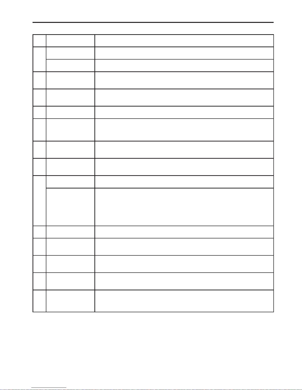
A INTRODUCTION
This manual consists of the following 13 sections:
No. Section Description
INDEX Index of the contents of this manual.
A
INTRODUCTION Brief explanation of each section.
B
HOW TO USE THIS
MANUAL
Instructions on how to use this manual.
C
TROUBLE–
SHOOTING
Describes the basic inspection procedures for electrical circuits.
D ABBREVIATIONS Defines the abbreviations used in this manual.
E
GLOSSARY OF
TERMS AND
SYMBOLS
Defines the symbols and functions of major parts.
F RELAY LOCATIONS
Shows position of the Electronic Control Unit, Relays, Relay Block, etc.
This section is closely related to the system circuit.
G
ELECTRICAL
WIRING ROUTING
Describes position of Parts Connectors, Splice points, Ground points, etc.
This section is closely related to the system circuit.
INDEX Index of the system circuits.
H
SYSTEM CIRCUITS
Electrical circuits of each system are shown from the power supply through ground
points. Wiring connections and their positions are shown and classified by code
according to the connection method. (Refer to the section, ”How to use this manual”).
The ”System Outline” and ”Service Hints” useful for troubleshooting are also contained
in this section.
(Only wiring information for complete circuits is included.)
I GROUND POINT Shows ground positions of all parts described in this manual.
J
POWER SOURCE
(Current Flow Chart)
Describes power distribution from the power supply to various electrical loads.
K CONNECTOR LIST
Describes the form of the connectors for the parts appeared in this book.
This section is closely related to the system circuit.
L
PART NUMBER OF
CONNECTORS
Indicates the part number of the connectors used in this manual.
M
OVERALL
ELECTRICAL
WIRING DIAGRAM
Provides circuit diagrams showing the circuit connections.
(Only wiring information for complete circuits is included.)

RAV4 (EM03T0U)
3
HOW TO USE THIS MANUAL B
This manual provides information on the electrical circuits installed on vehicles by
dividing them into a circuit for each system.
The actual wiring of each system circuit is shown from the point where the power
source is received from the battery as far as each ground point. (All circuit
diagrams are shown with the switches in the OFF position.)
When troubleshooting any problem, first understand the operation of the circuit
where the problem was detected (see System Circuit section), the power source
supplying power to that circuit (see Power Source section), and the ground points
(see Ground Point section). See the System Outline to understand the circuit
operation.
When the circuit operation is understood, begin troubleshooting of the problem
circuit to isolate the cause. Use Relay Location and Electrical Wiring Routing
sections to find each part, junction block and wiring harness connectors, wiring
harness and wiring harness connectors and ground points of each system circuit.
Internal wiring for each junction block is also provided for better understanding of
connection within a junction block.
Wiring related to each system is indicated in each system circuit by arrows
(from__, to__). When overall connections are required, see the Overall Electrical
Wiring Diagram at the end of this manual.
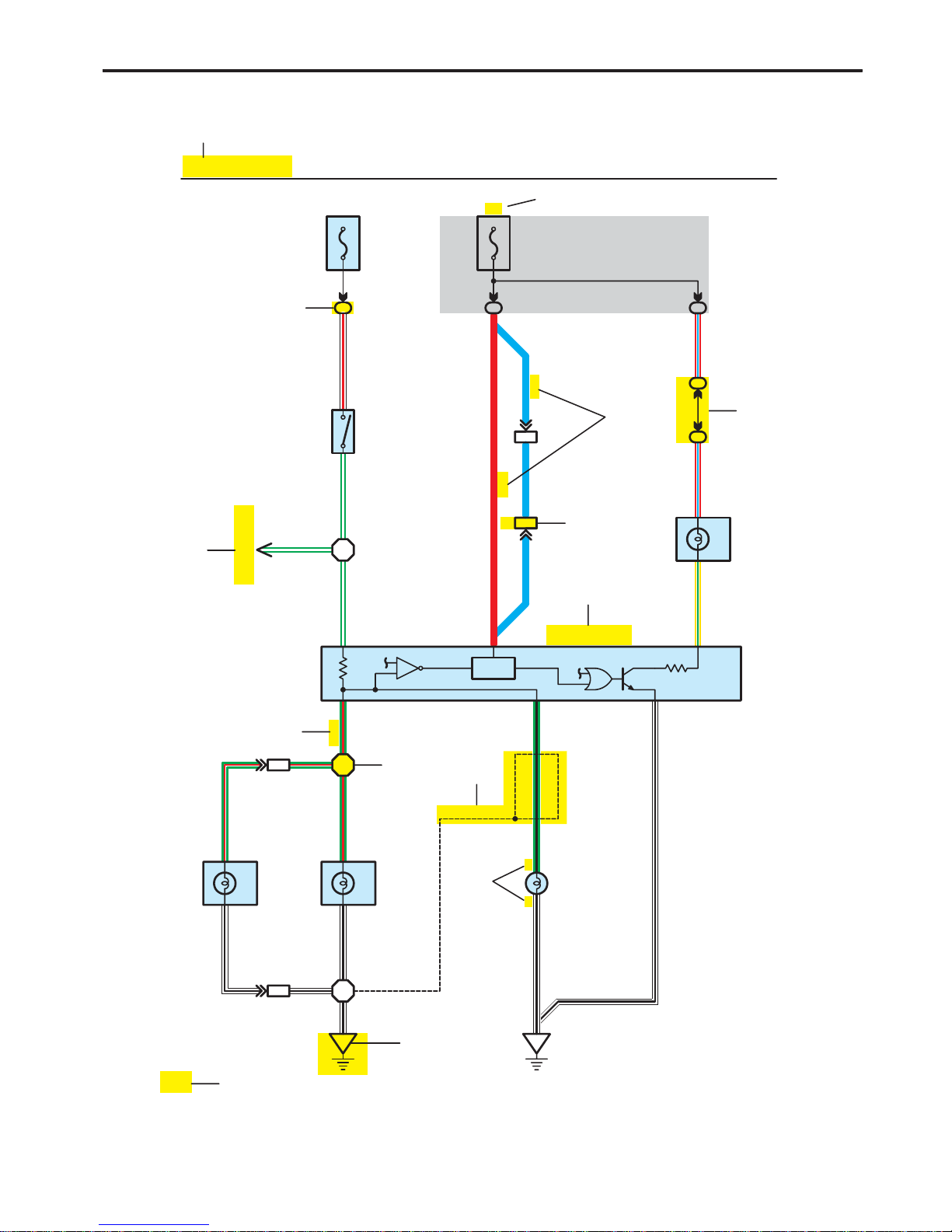
[B]
W – RG – W
Skid Control ECU
with Actuator
G – W
H7
Y – G
Combination Meter
R – L
Rear
Lights
R – L
(S/D) (S/D)
(S/D)
(W/G)
G – B
W – B
W – B
Rear Combination Lamp (LH)
H9
W – BW – B
Rear Combination Lamp (RH)
J7
W – B G – R
Stop
Stop
G – R G – R
7
LL
R
L
Stop Light
2
(BAT)
15A
STOP
(IG)
IB
IB
7.5A
GAUGE
34
1
[A]
H6
Stop Lamp SW
G – W
1
2
[D]
[C]
[E]
[F]
[G]
[M]
H4
Light Failure Sensor
3C
3C
15
CH1
CH114
7
15
48
13
4
50
[J]
[H]
[N]
[K]
[L]
[I]
11
H17
Center Stop
Lamp
(Shielded)
H1 H2
HJ1
W – B
G – R
HJ1
1
2
6
3
3
4
1
1
12
4
RAV4 (EM03T0U)
B HOW TO USE THIS MANUAL
* The system shown here is an EXAMPLE ONL Y . It is different to the actual
circuit shown in the SYSTEM CIRCUITS SECTION.
RAV4 (EM03T0U)
5
B
[A] : System Title
[B] : Indicates a Relay Block. No shading is used and
only the Relay Block No. is shown to distinguish it
from the J/B
Example: Indicates Relay Block No.1
[C] : ( ) is used to indicate different wiring and
connector, etc. when the vehicle model, engine
type, or specification is different.
[D] : Indicates related system.
[E] : Indicates the code for the (male and female)
connectors which are used to join two wire
harnesses. The connector code consists of two
alphabetical and one numerical characters.
Female Male ( )
The first character of the connector code indicates
the alphabetical code allocated to the wire harness
which has the female connector, and the second
shows that of the wire harness which has the male
connector.
The third character indicates a serial number used
to distinguish between the wire harness
combinations in cases when more than one of the
same combination of wire harnesses exist
(e.g. CH1 and CH2).
Symbol (
) indicates the male terminal connector.
Numbers outside connector codes indicate the pin
numbers of both male and female connectors.
[F] : Represents a part (all parts are shown in sky blue).
The code is the same as the code used in parts
position.
[G] : Junction Block (The number in the circle is the J/B
No. and the connector code is shown beside it).
Junction Blocks are shaded to clearly separate
them from other parts.
3C indicates that
it is inside
Junction Block
No.3
Example:
[H] : Indicates the wiring color.
Wire colors are indicated by an alphabetical code.
B = Black W = White BR = Brown
L = Blue V = Violet SB = Sky Blue
R = Red G = Green LG = Light Green
P = Pink Y = Yellow GR= Gray
O = Orange
The first letter indicates the basic wire color and the
second letter indicates the color of the stripe.
Example: L – Y
L
(Blue)Y(Yellow)
[I] : Indicates a shielded cable.
[J] : Indicates the pin number of the connector.
The numbering system is different for female and
male connectors.
Example:
Numbered in other
from upper left to
lower right
Numbered in other
from upper right to
lower left
Female
Male
[K] : Indicates the ground point. The code consists of the
two characters: A letter and number.
The first character of the code indicates the
alphabetical code allocated to the wire harness.
The second character indicates a serial number
used to distinguish between the ground points in
cases when more than one ground point exist on the
same wire harness.
[L] : Page No.
[M] : Indicates the ignition key position(s) when the
power is supplied to the fuse(s).
[N] : Indicates a wiring Splice Point.
Example:
[O]
[P]
[Q]
[R]
[S]
[T]
6
RAV4 (EM03T0U)
B HOW TO USE THIS MANUAL
Current is applied at all times through the STOP fuse to TERMINAL 2 of the stop lamp SW.
When the ignition SW is turned on, current flows from the GAUGE fuse to TERMINAL 8 of the light failure sensor, and also flows
through the rear lights warning light to TERMINAL 4 of the light failure sensor.
Stop Light Disconnection Warning
When the ignition SW is turned on and the brake pedal is pressed (Stop lamp SW on), if the stop light circuit is open, the current
flowing from TERMINAL 7 of the light failure sensor to TERMINALS 1, 2 changes, so the light failure sensor detects the
disconnection and the warning circuit of the light failure sensor is activated.
As a result, the current flows from TERMINAL 4 of the light failure sensor to TERMINAL 11 to GROUND and turns the rear lights
warning light on. By pressing the brake pedal, the current flowing to TERMINAL 8 of the light failure sensor keeps the warning
circuit on and holds the warning light on until the ignition SW is turned off.
: Parts Location
Code See Page Code See Page Code See Page
H4 36 H7 36 H17 38
H6 36 H9 38 J7 38
: Relay Blocks
Code See Page Relay Blocks (Relay Block Location)
1 18 R/B No.1 (Instrument Panel Brace LH)
: Junction Block and Wire Harness Connector
Code See Page Junction Block and Wire Harness (Connector Location)
3C 22 Instrument Panel Wire and J/B No.3 (Instrument Panel Brace LH)
IB 20 Instrument Panel Wire and Instrument Panel J/B (Lower Finish Panel)
: Connector Joining Wire Harness and Wire Harness
Code See Page Joining Wire Harness and Wire Harness (Connector Location)
CH1 42 Engine Room Main Wire and Instrument Panel Wire (Left Kick Panel)
HJ1 50 Instrument Panel Wire and Floor Wire (Right Kick Panel)
: Ground Points
Code See Page Ground Points Location
H1 50 Under the Left Center Pillar
H2 50 Back Panel Center
System Outline

RAV4 (EM03T0U)
7
B
[O] : Explains the system outline.
[P] : Indicates reference pages showing the parts locations in the system circuit on the vehicle.
Example : Code ”H4” (Light Failure Sensor) is on page 36 of the manual.
* The first character of the code indicates the alphabetical code allocated to the wire harness, and the
second character indicates the serial number of the parts connected to the wire harness.
Serial number for the connected parts
Code for the wire harness
Example : H 4
[Q] : Indicates the reference page showing the position on the vehicle of Relay Block Connectors in the system circuit.
Example : Connector ”1” is described on page 18 of this manual and is installed on the left side of the instrument
panel.
[R] : Indicates the reference page showing the position on the vehicle of J/B and Wire Harness in the system circuit.
Example : Connector ”3C” connects the Instrument Panel Wire and J/B No.3. It is described on page 22 of this
manual, and is installed on the instrument panel left side.
[S] : Indicates the reference page describing the wiring harness and wiring harness connector (the female wiring
harness is shown first, followed by the male wiring harness).
Example : Connector ”CH1” connects the Engine Room Main Wire (female) and Instrument Panel Wire (male).
It is described on page 42 of this manual, and is installed on the left side kick panel.
[T] : Indicates the reference page showing the position of the ground points on the vehicle.
Example : Ground point ”H2” is described on page 50 of this manual and is installed on the back panel center.
8
RAV4 (EM03T0U)
B HOW TO USE THIS MANUAL
The ground points circuit diagram shows the connections from all major parts to the respective ground points. When
troubleshooting a faulty ground point, checking the system circuits which use a common ground may help you identify
the problem ground quickly. The relationship between ground points (
A1, A2
and D4 shown below) can also be
checked this way .
I GROUND POINT
B36
W – BW – B
W – B
Junction
Connector
(Shielded)
(Shielded)
BR
W – B W – B
A25
W – B W – BW – B
W – B
Junction
Connector
17
18
19
20
3
8
7
4
1
6
5
34
2
DLC3
A20
L5
A22
A8
A5
A23
A11
I9
A21
K5
A1
A10
C4
C2
(E)
(E)
(E)
(L)
(E1)
(E1)
(E01)
(E02)
(LH E)
(E)
(E)
(RH E)
(–S)
(E)
(E)
(E)
(E)
(E)
(SG)
D2
D63
D60
A6
Throttle
Position SW
D4
(5L–E)
Junction
Connector
(Shielded)BRBRBR
LA1
3
DB1
12 7
CA1
5
HA1
KA1
3
IH2
HB4
912
D43
11
10
BR
BR
BR
BR
BR
W – B
W – B W – B
W – B
W – B
W – B
W – B
W – B
W – BW – BW – B
W – B
W – B
W – B
W – B
W – B
W – B
W – B
W – B
W – B
W – B
W – B
A1
Power Window
Master SW
Turn Signal Lamp
(Front RH)
Brake Fluid Level
Warning SW
Fog Lamp
(Front RH)
Fog Lamp
(Front LH)
Engine ECU
Injection
Pump Assembly
Clearance Lamp
(Front LH)
Clearance Lamp
(Front RH)
Headlamp
Leveling SW
Windshield
Wiper Motor
Turn Signal Lamp
(Front LH)
Pressure SW
Headlamp Leveling
Motor (RH)
Cooling Fan
Motor No.3
Power Window
Master SW
Headlamp Leveling
Motor (LH)
H23
(E)
(E)
A24
(GND2)
(GND1)
(GND)
(GND)
B19
(Shielded)
(Shielded)
(Shielded)
(Shielded)
W – B
W – B
W – B
W – BW – B
W – B
W – B
W – B
21
AB1
12
AB1
W – B
W – B
W – B
W – B
Skid Control ECU
with Actuator
Option Connector
(Vacuum)
6
AB1
A2
16
* The system shown here is an EXAMPLE ONLY. It is different to the actual circuit shown in the SYSTEM CIRCUITS SECTION.
RAV4 (EM03T0U)
9
B
The ”Current Flow Chart” section, describes which parts each power source (fuses, fusible links, and circuit breakers)
transmits current to. In the Power Source circuit diagram, the conditions when battery power is supplied to each system
are explained. Since all System Circuit diagrams start from the power source, the power source system must be fully
understood.
AM2
AM1
IG2
ACC
IG1
ST1
ST2
W – R
W
J POWER SOURCE (Current Flow Chart)
The chart below shows the route by which current flows from the battery to each electrical source
(Fusible Link, Circuit Breaker, Fues, etc.) and other parts
30A AM2
Starter
Battery
Fusible Link Block
100A ALT
2
6
6
Short Pin
10A ECU–B
7.5A DOME
2
15A EFI
10A HAZARD
20A RADIO NO.1
10A HORN
60A ABS
2
2
S 2
5
Engine Room R/B (See Page 20)
194
187
180
166
210
214
230
112
122
Page
ABS
ABS and Traction Control
Cruise Control
Electronically Controlled Transmission
Multiplex Communication System
Fuse
STOP
20A
10A
DOME
Cigarette Lighter
Combination Meter
Headlight
Interior Light
Key Reminder and Seat Belt Warning
Light Auto Turn Off System
System
Theft Deterrent and Door Lock Control
1.25B
FL MAIN
Power Source
50A MAIN
4
1
121W – R
20A DEFOG
B – Y
8
2
H8
W – R
Ignition SW
1
1
7.5A DOME
2
1
R
W
AH1
7
AH1
BA1
1
6
W
WW
Battery
B
B
B
2
21
2
2
2
2
7.5A AM1
15A HAZ–RADIO
1
21
2
W
∗ The system shown here is an EXAMPLE ONLY. It is different to the actual circuit shown in the SYSTEM CIRCUITS SECTION.
Black
B1
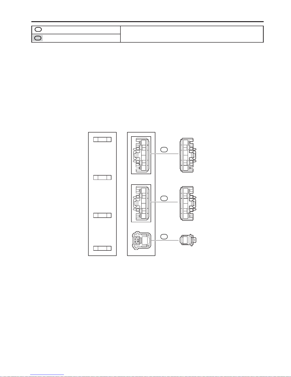
K CONNECTOR LIST
1234
Black
A1
1234
5678
A2
12345 76
Gray
A3
12
3456
123 45
678910111213
B2
[A]
[C]
[D]
[B]
Gray
K CONNECTOR LIST
123 45
6 7 8 9 10 11 12 13
12345
13 6789101112
BA1
Black
BD2
Gray
[F]
[E]
12 34
567891011
11
43 21
5678910
10
RAV4 (EM03T0U)
B HOW TO USE THIS MANUAL
[A] : Indicates connector to be connected to a part. (The numeral indicates the pin No.)
[B] : Junction Connector
Indicates a connector which is connected to a short terminal.
Junction Connector
Short Terminal
Junction connector in this manual include a short terminal which is
connected to a number of wire harnesses. Always perform
inspection with the short terminal installed.
[C] : Parts Code
The first letter of the code is taken from the first letter of part, and the numbers indicates its order in parts which
start with the same letter.
[D] : Connector Color
Connectors not indicated are milky white in color.
[E] : Indicates the connector shapes which are used to join wire harnesses.
On Left : Female connector shapes
On Right : Male connector shapes
Numbers indicate pin numbers.
[F] : Indicates connector colors. (Connectors with not indicated colors are white)
A1
L PART NUMBER OF CONNECTORS
Code
90980–11019
Part Number
B22 Door Courtesy SW (Front LH)
Code
90980–12470
A2 Inlet Air Temp. Sensor 90980–1 1163 B23 Front Seat Outer Belt (LH) 90980–12253
A3 Air Flow Meter 90980–12292 B24 Blower SW (Rear Heater) 90980–10463
A4 A/C Pressure Sensor 90980–10845
90980–10943
B25 Front Seat Outer Belt (RH) 90980–12253
A5 Pressure SW
90980–11156
B26 Door Courtesy SW (Front RH) 90980–12470
A6 Clearance Lamp (Front RH)
90980–11314
B27
Cooling Fan ECU No.1
A7 Headlamp (RH)
90980–11016
Cooling Fan ECU No.2
90980–10735A8 Headlamp Leveling Motor (RH)
90980–11252
Water Temp. Sensor (Radiator)
A9 Brake Vacuum Warning SW
90980–11207
Fuel Filter Warning SW
Brake Fluid Level Warning SW
90980–11599
Door Control Relay (LH)
90980–10121Windshield Washer Motor Step Lamp (LH)
Airbag Sensor (Front RH) Junction Connector
A10
A11
A12
A13 Airbag Squib
90980–12490
Junction Connector 90980–1 1398
B28
B29
B30
B32
B33
B34
B35
Part NumberPart NamePart Name
[A]
[B]
[C]
Turn Signal Lamp (Front RH)
90980–11856
90980–10841
90980–11003
90980–10789
RAV4 (EM03T0U)
11
B
[A] : Part Code
[B] : Part Name
[C] : Part Number
Toyota Part Number are indicated.
Not all of the above part numbers of the connector are established for the supply.
To Ignition SW
IG Terminal
Fuse
VoltmeterSW 1
Relay
SW 2
Solenoid
[A]
[B]
[C]
Ohmmeter
SW
Ohmmeter
Diode
Digital Type Analog Type
12
RAV4 (EM03T0U)
C TROUBLESHOOTING
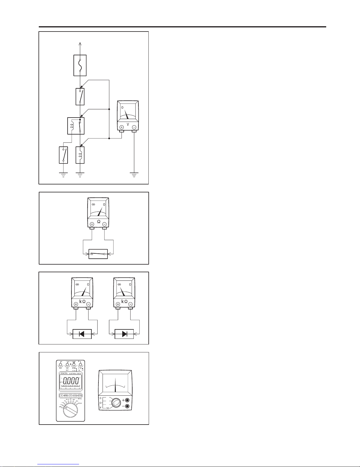
VOLTAGE CHECK
(a) Establish conditions in which voltage is present at the check
point.
Example:
[A] – Ignition SW on
[B] – Ignition SW and SW 1 on
[C] – Ignition SW, SW 1 and Relay on (SW 2 off)
(b) Using a voltmeter, connect the negative lead to a good ground
point or negative battery terminal, and the positive lead to the
connector or component terminal.
This check can be done with a test light instead of a voltmeter.
CONTINUITY AND RESISTANCE CHECK
(a) Disconnect the battery terminal or wire so there is no voltage
between the check points.
(b) Contact the two leads of an ohmmeter to each of the check
points.
If the circuit has diodes, reverse the two leads and check
again.
When contacting the negative lead to the diode positive side
and the positive lead to the negative side, there should be
continuity.
When contacting the two leads in reverse, there should be no
continuity.
(c) Use a volt/ohmmeter with high impedance (10 kΩ/V
minimum) for troubleshooting of the electrical circuit.
To Ignition SW
IG Terminal
Test Light
RelayLight
SW 2 Solenoid
Disconnect
Short [A]
Disconnect
Disconnect
SW 1
Fuse Case
Short [B]
Short [C]
Pull Up
Press Down Press Down
Pull Up
RAV4 (EM03T0U)
13
C
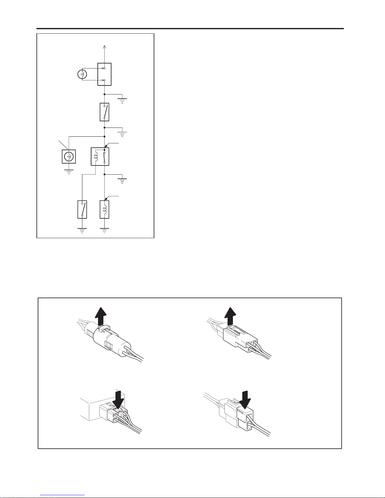
FINDING A SHORT CIRCUIT
(a) Remove the blown fuse and disconnect all loads of the fuse.
(b) Connect a test light in place of the fuse.
(c) Establish conditions in which the test light comes on.
Example:
[A] – Ignition SW on
[B] – Ignition SW and SW 1 on
[C] – Ignition SW, SW 1 and Relay on (Connect the
Relay) and SW 2 off (or Disconnect SW 2)
(d) Disconnect and reconnect the connectors while watching the
test light.
The short lies between the connector where the test light
stays lit and the connector where the light goes out.
(e) Find the exact location of the short by lightly shaking the
problem wire along the body.
CAUTION:
(a) Do not open the cover or the case of the ECU unless
absolutely necessary. (If the IC terminals are touched,
the IC may be destroyed by static electricity.)
(b) When replacing the internal mechanism (ECU part) of
the digital meter, be careful that no part of your body or
clothing comes in contact with the terminals of leads
from the IC, etc. of the replacement part (spare part).
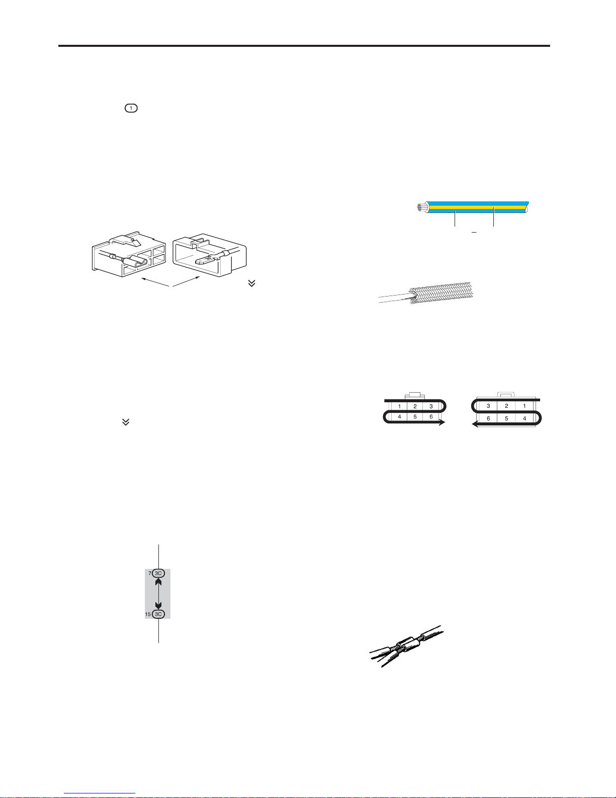
DISCONNECTION OF MALE AND FEMALE
CONNECTORS
To pull apart the connectors, pull on the connector itself, not
the wire harness.
HINT : Check to see what kind of connector you are
disconnecting before pulling apart.
10
3
0.2
1
1
(mm)
Reference:
Tool
Up
Example:
(Case 1)
Terminal Retainer
Terminal Retainer
[Retainer at Full Lock Position]
[Retainer at Temporary Lock Position]
Stopper
Terminal
Retainer
Secondary
Locking Device
Example:
(Case 2)
14
RAV4 (EM03T0U)
C TROUBLESHOOTING
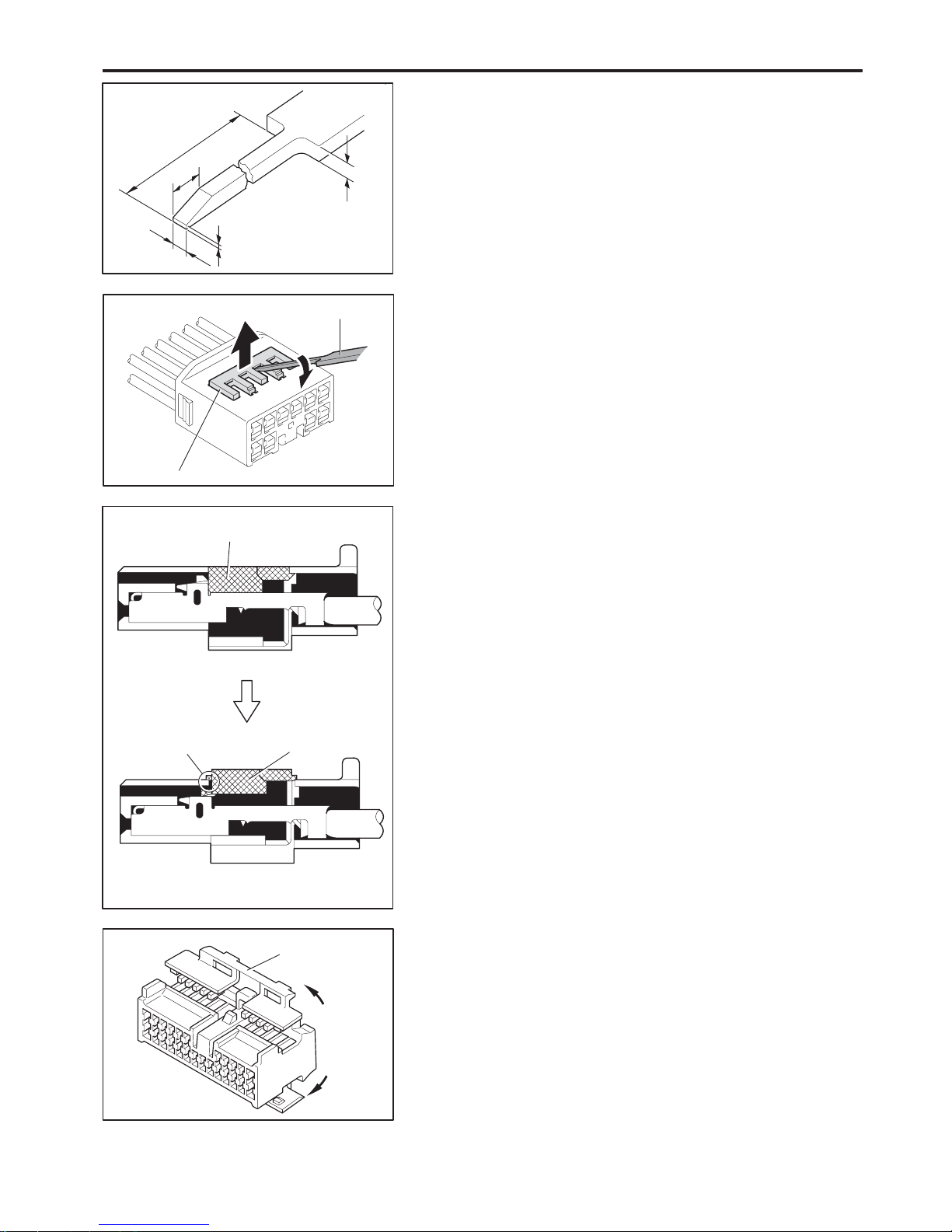
HOW TO REPLACE TERMINAL
(with terminal retainer or secondary locking device)
1. PREPARE THE SPECIAL TOOL
HINT : To remov e the te rmin al fro m the connector, please
construct and use the special tool or like object shown on
the left.
2. DISCONNECT CONNECT OR
3. DISENGAGE THE SECONDARY LOCKING DEVICE OR
TERMINAL RETAINER.
(a) Locking device must be disengaged before the terminal
locking clip can be released and the terminal removed from
the connector.
(b) Use a special tool or the terminal pick to unlock the secondary
locking device or terminal retainer.
NOTICE:
Do not remove the terminal retainer from connector body.
[A] For Non–Waterproof Type Connector
HINT : The needle insertion position varies according to the
connector’s shape (number of terminals etc.), so
check the position before inserting it.
”Case 1”
Raise the terminal retainer up to the temporary lock
position.
”Case 2”
Open the secondary locking device.
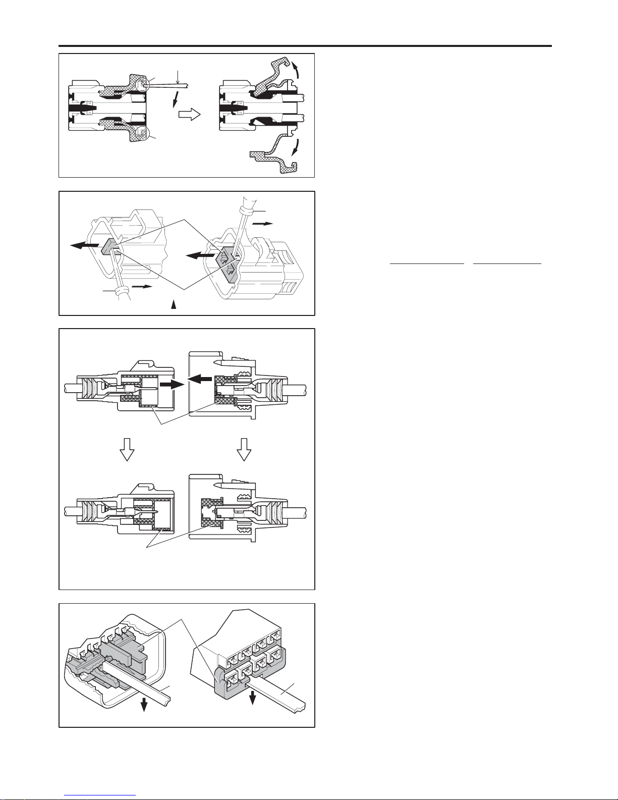
Tool
Tab
Tab
Terminal
Retainer
Access Hole
( Mark)
Tool
Tool
[Female]
Example:
[Male]
(Case 1)
[Male] [Female]
Retainer
at Full Lock Position
Retainer
at Temporary Lock Position
Terminal Retainer
[Male]
Press Down
[Female]
Press Down
Tool
Tool
Example:
(Case 2)
RAV4 (EM03T0U)
15
C
[B] For Waterproof Type Connector
HINT : Termi nal r etain er co lor is di ffere nt
according to connector body.
Example:
Terminal Retainer
: Connector Body
Black or White : Gray
Black or White : Dark Gray
Gray or White : Black
”Case 1”
Type where terminal retainer is pulled
up to the temporary lock position (Pull
Type).
Insert the special tool into the terminal
retainer access hole (YMark) and pull
the terminal retainer up to the
temporary lock position.
HINT : The needle insertion position varies
according to the connector’s shape
(Number of terminals etc.), so check
the position before inserting it.
”Case 2”
Type which cannot be pulled as far as
Power Lock insert the tool straight into
the access hole of terminal retainer as
shown.
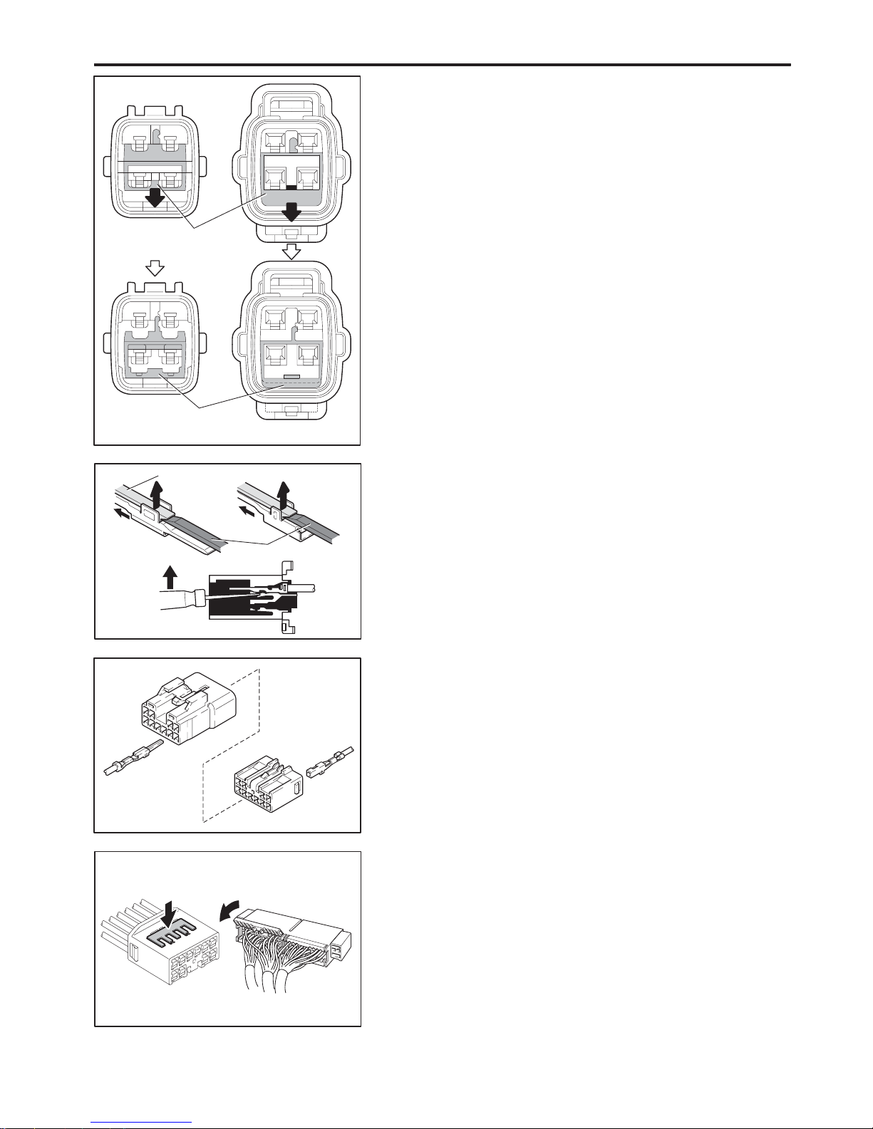
Retainer at
Full Lock Position
[Male] [Female]
Retainer at
Temporary Lock Position
Locking Lug
Tool
16
RAV4 (EM03T0U)
C TROUBLESHOOTING
Push the terminal retainer down to the temporary lock position.
(c) Release the locking lug from terminal and pull the terminal out
from rear.
4. INSTALL TERMINAL TO CONNECTOR
(a) Insert the terminal.
HINT:
1. Make sure the terminal is positioned correctly.
2. Insert the terminal until the locking lug locks firmly.
3. Insert the terminal with terminal retainer in the temporary lock
position.
(b) Push the secondary locking device or terminal retainer in to
the full lock position.
5. CONNECT CONNECT OR

∗ The titles given inside the components are the names of the terminals (terminal codes) and are not treated as being
abbreviations.
RAV4 (EM03T0U)
17
ABBREVIATIONS D
ABBREVIATIONS
The following abbreviations are used in this manual.
2WD = Two Wheel Drive Vehicles
4WD = Four Wheel Drive Vehicles
A/C = Air Conditioning
A/T = Automatic Transaxle
ABS = Anti–Lock Brake System
ACIS = Acoustic Control Induction System
CAN = Controller Area Network
CPU = Central Processing Unit
ECU = Electronic Control Unit
EPS = Electric Motor Power Steering
ESA = Electronic Spark Advance
ETCS–i = Electronic Throttle Control System–intelligent
FL = Fusible Link
IC = Integrated Circuit
J/B = Junction Block
LED = Light Emitting Diode
LH = Left–Hand
LSD = Limited Slip Differential
R/B = Relay Block
RH = Right–Hand
SFI = Sequential Multiport Fuel Injection
SRS = Supplemental Restraint System
SW = Switch
TEMP. = Temperature
TRAC = Traction Control
TVIP = TOYOTA Vehicle Intrusion Protection
VSC = Vehicle Stability Control
VSV = Vacuum Switching Valve
VVT = Variable Valve Timing
VVT–i = Variable Valve Timing–intelligent
w/ = With
w/o = Without

18
RAV4 (EM03T0U)
E GLOSSARY OF TERMS AND SYMBOLS
BATTERY
Stores chemical energy and
converts it into electrical energy.
Provides DC current for the auto’s
various electrical circuits.
GROUND
The point at which wiring attaches to
the Body, thereby providing a return
path for an electrical circuit; without a
ground, current cannot flow.
CAPACITOR (Condenser)
A small holding unit for temporary
storage of electrical voltage.
HEADLIGHTS
Current flow causes a headlight
filament to heat up and emit light. A
headlight may have either a single
(1) filament or a double (2) filament
1. SINGLE
FILAMENT
CIGARETTE LIGHTER
An electric resistance heating
element.
2. DOUBLE
FILAMENT
CIRCUIT BREAKER
Basically a reusable fuse, a circuit
breaker will heat and open if too
much current flows through it.
Some units automatically reset when
cool, others must be manually reset.
HORN
An electric device which sounds a
loud audible signal.
DIODE
A semiconductor which allows
current flow in only one direction.
IGNITION COIL
Converts low–voltage DC current
into high–voltage ignition current for
firing the spark plugs.
DIODE, ZENER
A diode which allows current flow in one
direction but blocks reverse flow only up
to a specific voltage. Above that potential,
it passes the excess voltage. This acts as
a simple voltage regulator.
LIGHT
Current flow through a filament
causes the filament to heat up and
emit light.
PHOTODIODE
The photodiode is a semiconductor
which controls the current flow
according to the amount of light.
LED (LIGHT EMITTING DIODE)
Upon current flow, these diodes emit
light without producing the heat of a
comparable light.
DISTRIBUTOR, IIA
Channels high–voltage current from
the ignition coil to the individual
spark plugs.
METER, ANALOG
Current flow activates a magnetic
coil which causes a needle to move,
thereby providing a relative display
against a background calibration.
FUSE
A thin metal strip which burns through
when too much current flows through it,
thereby stopping current flow and
protecting a circuit from damage.
FUSIBLE LINK
METER, DIGITAL
Current flow activates one or many
LED’s, LCD’s, or fluorescent
displays, which provide a relative or
digital display.
FUEL
FUSIBLE LINK
A heavy–gauge wire placed in high
amperage circuits which burns through on
overloads, thereby protecting the circuit.
The numbers indicate the crosssection
surface area of the wires.
(for Medium Current Fuse)
(for High Current Fuse or
Fusible Link)
MOTOR
A power unit which converts
electrical energy into mechanical
energy, especially rotary motion.
M
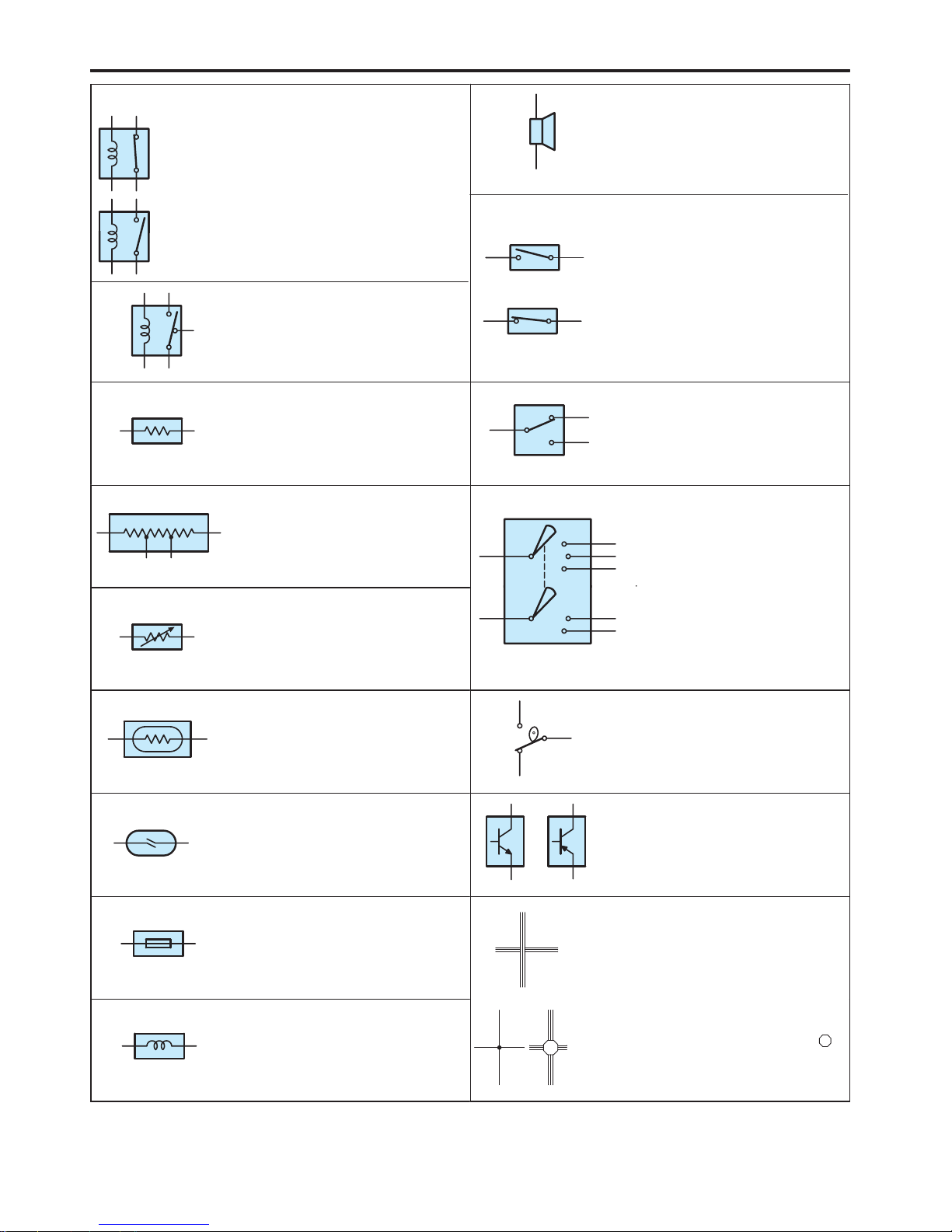
RAV4 (EM03T0U)
19
E
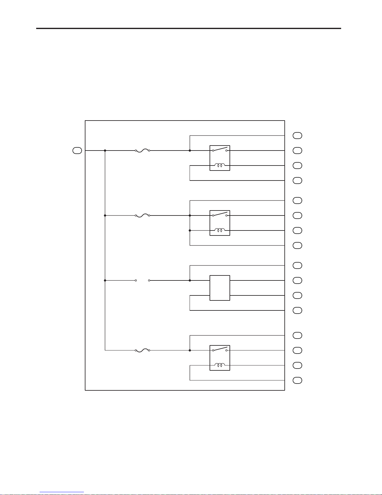
RELAY
Basically, an electrically operated
switch which may be normally
closed (1) or open (2).
Current flow through a small coil
creates a magnetic field which either
opens or closes an attached switch.
1. NORMALLY
CLOSED
2. NORMALLY
OPEN
SWITCH, MANUAL
Opens and closes
SPEAKER
An electromechanical device which
creates sound waves from current
flow.
RELAY, DOUBLE THROW
A relay which passes current
through one set of contacts or the
other.
Opens and closes
circuits, thereby
stopping (1) or
allowing (2) current
flow.
1. NORMALLY
OPEN
2. NORMALLY
CLOSED
RESISTOR
An electrical component with a fixed
resistance, placed in a circuit to
reduce voltage to a specific value.
SWITCH, DOUBLE THROW
A switch which continuously passes
current through one set of contacts
or the other.
RESISTOR, TAPPED
A resistor which supplies two or
more different non adjustable
resistance values.
SWITCH, IGNITION
A key operated switch with several
positions which allows various
circuits, particularly the primary
ignition circuit, to become
operational.
RESISTOR, VARIABLE or RHEOSTAT
A controllable resistor with a variable
rate of resistance.
Also called a potentiometer or
rheostat.
operational.
SENSOR (Thermistor)
A resistor which varies its resistance
with temperature.
SWITCH, WIPER PARK
Automatically returns wipers to the
stop position when the wiper switch
is turned off.
(Reed Switch Type)
SENSOR, SPEED
Uses magnetic impulses to open
and close a switch to create a signal
for activation of other components.
TRANSISTOR
A solidstate device typically used as
an electronic relay; stops or passes
current depending on the voltage
applied at ”base”.
SHORT PIN
Used to provide an unbroken
connection within a junction block.
WIRES
Wires are always drawn as
straight lines on wiring
diagrams.
Crossed wires (1) without a
black dot at the junction are
(1) NOT
CONNECTED
SOLENOID
An electromagnetic coil which forms
a magnetic field when current flows,
to move a plunger, etc.
black dot at the junction are
not joined;
crossed wires (2) with a
black dot or octagonal ( )
mark at the junction are
spliced (joined)
connections.
(2) SPLICED
20
RAV4 (EM03T0U)
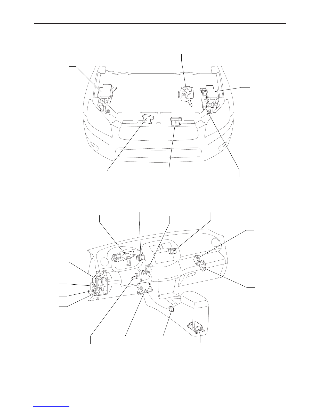
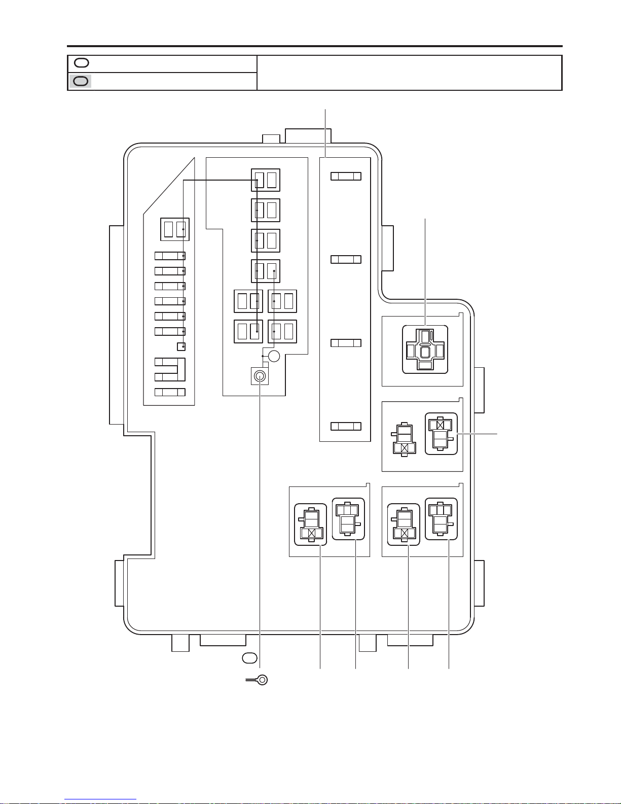
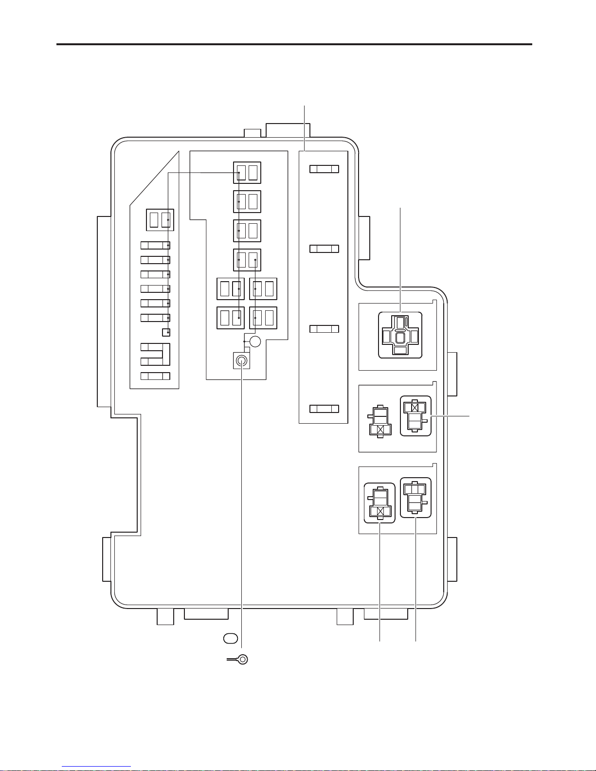
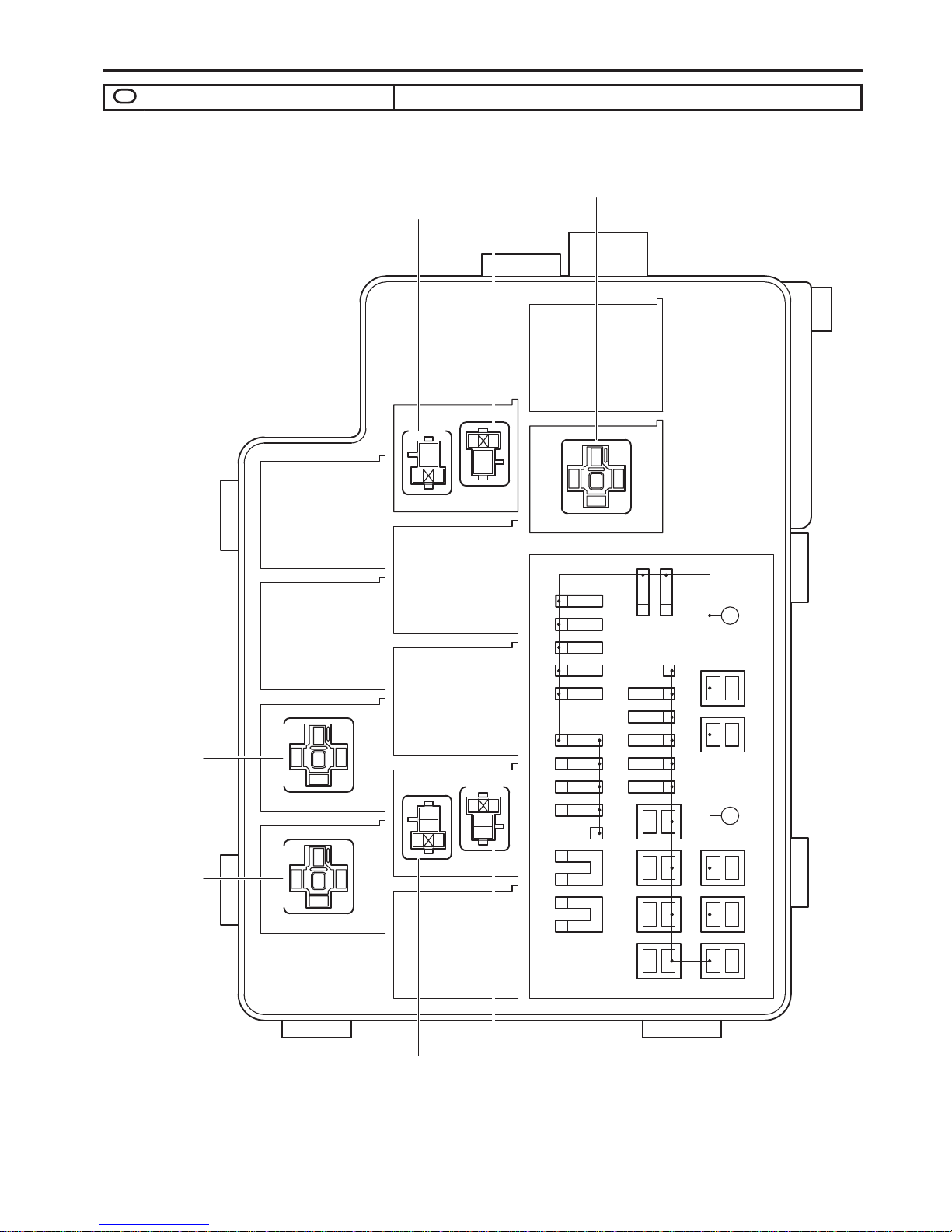
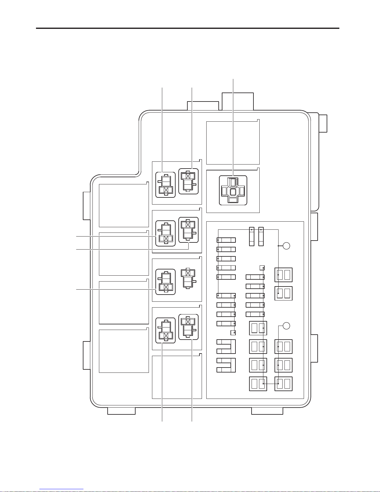
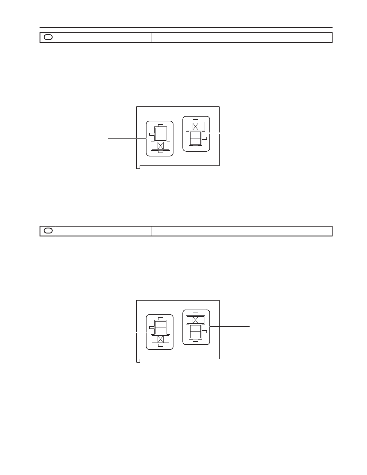
F RELAY LOCATIONS
[Engine Compartment]
Cooling Fan ECU(LH)(*1)
Cooling Fan ECU(*2)
Engine Room
J/B No.1
Engine Room
R/B No.1
Cooling Fan ECU(RH)
Engine Room
R/B No.2
Skid Control ECU
with Actuator
Engine Control
Module
*1: w/ Trailer Towing
*2: w/o Trailer Towing
[Instrument Panel]
Main Body ECU
4WD
Control ECU
Tire Pressur
e
Warning EC
U
Instrument
Panel J/B
R/B No.5
Power Steering
ECU
R/B No.6
R/B No.7
Transponder Key
ECU
Transponder
Key Amplifier
A/C Amplifier
Shift Lock Control
ECU
Airbag Sensor
Assembly Center
J/B No.3 J/B No.4
RAV4 (EM03T0U)
21
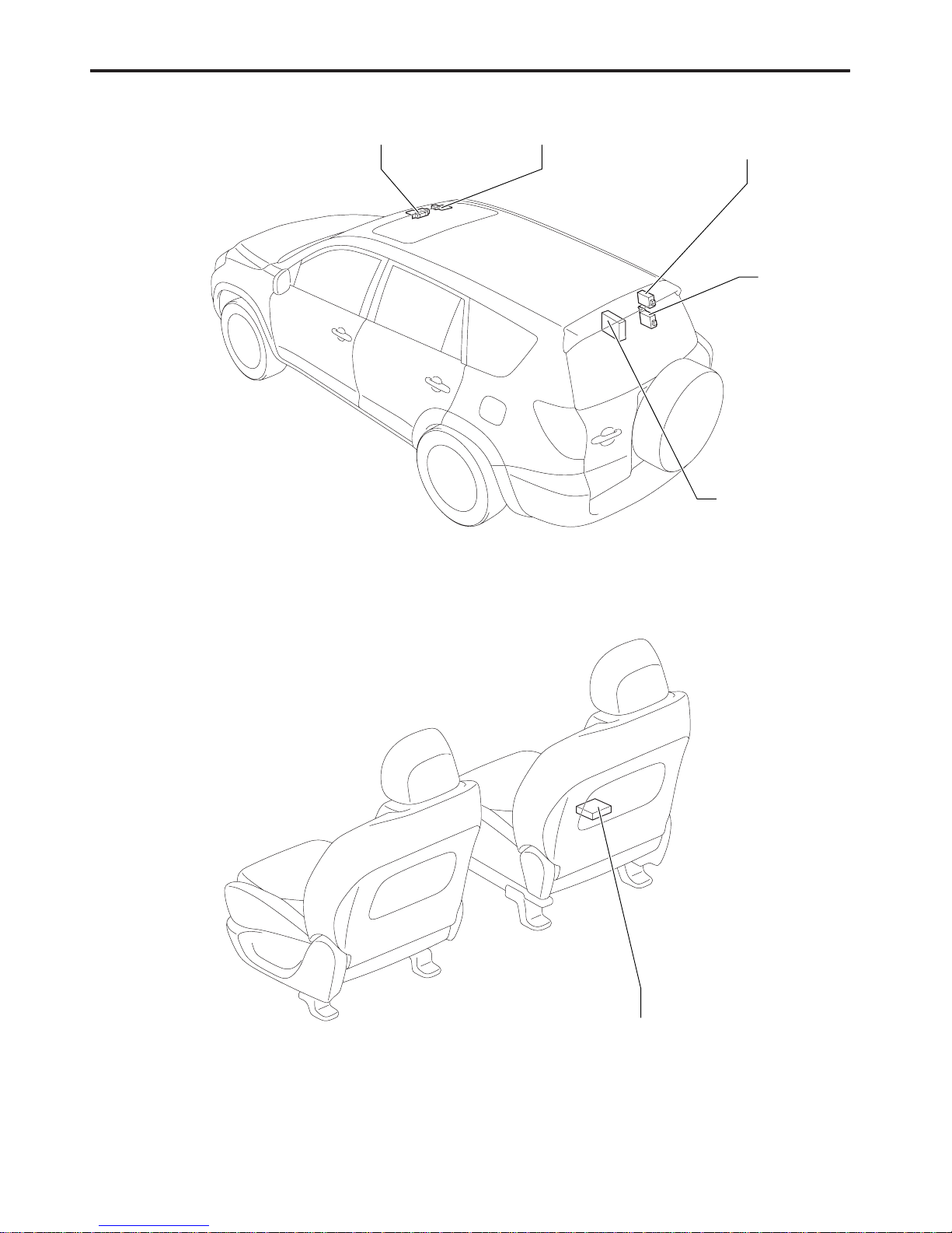
F
[Body]
Tire Pressure Warning
Antenna and Receiver
Door Contro
l
Receiver
Overhead J/B Sliding Roof Control ECU
Stereo Componen
t
Amplifier
[Seat]
Occupant Classification ECU
2 30A
AM2
AMP
1
2 30A
IG2
1
2 15A
HAZ
1
2 10A
ETCS
1
2 10A 1
2 10A
EFI NO.1
1
2 10A
EFI NO.2
21
*1
*2
*3
21
21
21
21
12
*4 *5
*6
3
BRK RelayIG2 Relay
5
12
3
5
12
12
3
5
1
20A
EFI MAIN
2
VSC MTR Relay
* 1:60A EMPS (for High Current)
* 2:80A MAIN (for High Current)
* 3:140A ALT (w/ Trailer Towing)
120A ALT (w/o Trailer Towing)
(for High Current)
* 4:50A P/I (for High Current)
* 5:30A ABS2 (for High Current)
* 6:50A ABS1 (for High Current)
1 10A
HORN
2
21 20A
A/F
3
5
1
VSC FAIL
Relay
2
4
Unit A
3
F/PMP
Relay
MG CLT
Relay
5
12
3
5
12
4
1D
(from Engine Wire)
Wire Color : W
1
22
RAV4 (EM03T0U)
F RELAY LOCATIONS
1
: Engine Room R/B No.1
: Engine Room J/B No.1
Engine Compartment Left (See Page 20)
[2GR–FE] (Inner Circuit : See Page 25)
2 30A
AM2
AMP
1
2 30A
IG2
1
2 15A
HAZ
1
2 10A
ETCS
1
2 10A 1
2 10A
EFI NO.1
1
2 10A
EFI NO.2
21
*1
*2
*3
21
21
21
21
12
*4 *5
*6
3
BRK
Relay
IG2
Relay
5
12
3
5
12
12
3
5
1
20A
EFI MAIN
2
VSC MTR Relay
* 1:60A EMPS (for High Current)
* 2:80A MAIN (for High Current)
* 3:120A ALT (for High Current)
* 4:50A P/I (for High Current)
* 5:30A ABS2 (for High Current)
* 6:50A ABS1 (for High Current)
1 10A
HORN
2
3
5
1
VSC FAIL
Relay
2
4
Unit A
1D
1
(from Engine Wire)
Wire Color : W
RAV4 (EM03T0U)
23
F
[2AZ–FE]
Unit A
2
3
4
5
6
7
8
1
8
7
6
5
4
3
2
1
Back View
(from Engine Room
Main Wire)
(from Engine Room
Main Wire)
(from Engine Room
Main Wire)
1
8
7
6
5
4
3
2
1
1
2
3
4
5
6
7
8
1
1A
1B
1C
Top View
24
RAV4 (EM03T0U)
F RELAY LOCATIONS
1
: Engine Room R/B No.1
: Engine Room J/B No.1
Engine Compartment Left (See Page 20)
(Inner Circuit : See Page 25)
1
1C
1
1A
4
1A
3
1A
2
1A
5
1A
8
1A
7
1A
6
1A
1
1B
4
1B
3
1B
2
1B
5
1B
8
1B
7
1B
6
1B
Unit A
12
12
20A EFI MAIN
EFI MAIN Relay
HORN Relay
A/F Relay
10A HORN
12
20A A/F
RAV4 (EM03T0U)
25
F
[Engine Room J/B No.1 Inner Circuit]
2
DOME
10A
2 10A
ECU-B
2 20A
RAD NO.1
2
DEICER
20A
217.5A
ECU-B2
217.5A
RSE
1
DCC
1
1
2*11
1
2
AC INV
15A1
2
TOWING
30A1
21
2
*2
*3
1
1*42
1
2 10A
2 10A
2 10A
HEAD RL
1
2 10A
HEAD LL
HEAD RH
HEAD LH
12
3
5
12
3
5
12
3
5
3
5
12
3
5
12
3
5
1
DRL NO.3
Relay
HEAD Relay
DRL NO.4
Relay
FAN NO.1
Relay
* 1:50A HTR (for High Current)
* 2:50A FAN1 (for High Current)
* 3:50A FAN2 (for High Current)
* 4:50A HEAD MAIN
(for High Current)
DRL NO.2
Relay
DEICER
Relay
2
3
5
12
FAN NO.2
Relay
26
RAV4 (EM03T0U)
F RELAY LOCATIONS
2
: Engine Room R/B No.2 Engine Compartment Right (See Page 20)
[2GR–FE]
2
DOME
10A
2 10A
ECU-B
2 20A
RAD NO.1
2
DEICER
20A
217.5A
ECU-B2
1
DCC
1
1
2*11
1
21
2
*2
*3
1
1*42
1
2 10A
2 10A
2 10A
HEAD RL
1
2 10A
HEAD LL
HEAD RH
HEAD LH
12
3
5
3
5
12
3
5
12
3
5
12
3
5
12
3
5
12
3
5
1
DRL NO.3
Relay
HEAD Relay
DRL NO.4
Relay
FAN NO.3
Relay
FAN NO.2
Relay
FAN NO.1
Relay
* 1:50A HTR (for High Current)
* 2:30A CDS (for High Current)
* 3:30A RDI (for High Current)
* 4:50A HEAD MAIN
(for High Current)
DRL NO.2
Relay
DEICER
Relay
2
3
5
12
RAV4 (EM03T0U)
27
F
[2AZ–FE]
28
RAV4 (EM03T0U)
F RELAY LOCATIONS
5
: R/B No.5 Cowl Side Left (See Page 20)
3
5
1
ACC Relay
2
3
PWR OUTLET Relay
5
12
6
: R/B No.6 Cowl Side Left (See Page 20)
3
5
1
FR FOG Relay
2
3
INVT Relay
5
12
3
ST Relay
5
12
RAV4 (EM03T0U)
29
F
7
: R/B No.7 Cowl Side Left (See Page 20)
 Loading...