

Toyota 99-8212 User Manual
INSTALLATION INSTRUCTIONS FOR PART 99-8212
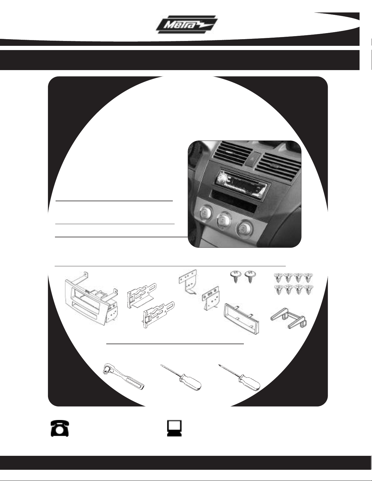
APPLICA TIONS
2004-2008 Toyota Solara
99-8212
KIT FEATURES
• DIN Head Unit Provisions with Pocket
• ISO DIN Head Unit Pro
KIT COMPONENTS
visions with Poc
ket
A) Radio Housing w/ Pocket • B) ISO Brackets
C) Radio Housing Brackets • D) (2) PTH-838 Phillips Screws • E) (8) PFH-614 Phillips Screws
F) Trim Plate • G) X-9002 Radio Support Bracket
D
C
A
B
TOOLS REQUIRED:
Socket Wrenc h • Small Flat Blade Screwdriver • Phillips Scr ewdriver
F
E
G
1-800-221-0932 www.metraonline.com
© COPYRIGHT 2004-2007 METRA ELECTRONICS CORPORATION Rev.10-02-07

99-8212
Dash Disassembly . . . . . . . . . . . . . . . . . . . . . . . . . . . . . . . . . 1
Kit Assembly . . . . . . . . . . . . . . . . . . . . . . . . . . . . . . . . . . . . . . 2-4
Final Assembly . . . . . . . . . . . . . . . . . . . . . . . . . . . . . . . . . . . . 5
TABLE OF CONTENTS
99-8212
2004-2008 TOYOTA SOLARA
A
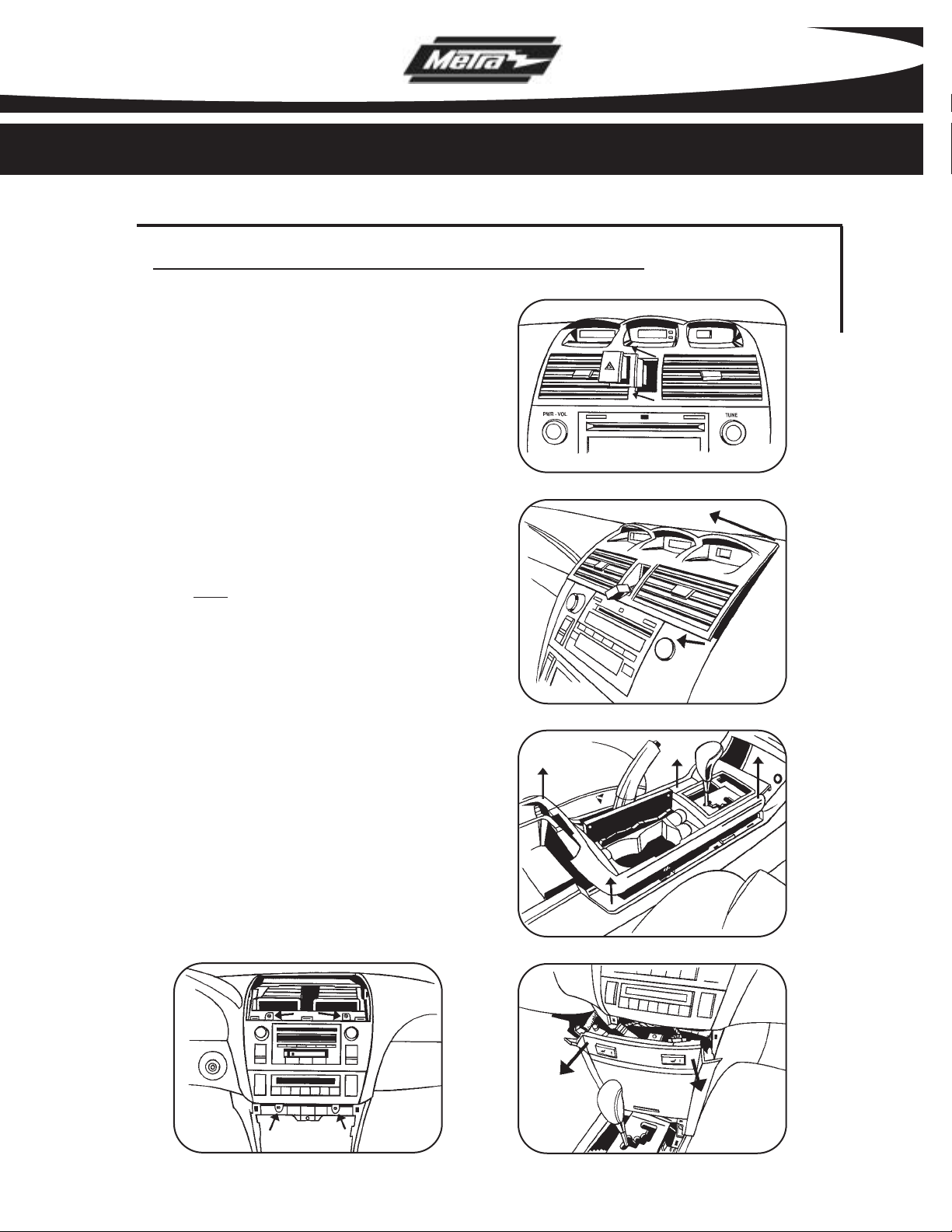
Disconnect the negative battery
1
terminal to prevent an accidental
short circuit.
2
Remove the cover from the hazard
switch then unclip and remove the
switch.
Unclip and remove panel above radio
3
including A/C vents and clock.
TIP: Start pulling from the inside of
the hazard switch cavity.
(Figure A)
B
(Figure B)
DASH DISASSEMBLY
Unclip and remove panel surrounding
4
shifter.
Unclip and remove pocket and seat
5
heater switch panel.
Remove (4) 10mm screws to extract
6
radio from sub dash.
E
(Figure C)
(Figure D)
(Figure E)
C
D
1
 Loading...