

Toyota 8FBCU20-32, 8FBCHU25 Repair Manual

8FBCU 20, 25, 28, 30, 32
8FBCHU 25
VOL. 1
Pub. No. CU346

SECTION INDEX
NAME SECTION
GENERAL 0
BATTERY 1
CONTROL SYSTEM 2
MULTI-FUNCTION DISPLAY 3
TROUBLESHOOTING 4
MOTOR 5
DRIVE UNIT 6
FRONT AXLE 7
REAR AXLE 8
STEERING 9
BRAKE 10
BODY 11
MATERIAL HANDLING SYSTEM 12
MAST 13
CYLINDER 14
OIL PUMP 15
OIL CONTROL VALVE 16
SAS FUNCTIONS 17
APPENDIX 18
Sections indicated by solid characters are included in this manual.
Sections indicated by half-tone characters: See vol. 2.

0-1
0
GENERAL
Page Page
EXTERIOR VIEWS .......................... 0-2
VEHICLE MODEL............................ 0-3
FRAME NUMBER............................ 0-4
HOW TO USE THIS MANUAL ..... 0-5
EXPLANATION METHOD ................ 0-5
TERMINOLOGY................................ 0-6
ABBREVIATIONS ............................. 0-6
SI UNITS ........................................... 0-7
OPERATIONAL TIPS ..................... 0-8
JACK-UP POINT ........................... 0-10
RECOMMENDED LUBRICANT
QUANTITY & TYPES ................. 0-20
LUBRICATION CHART................ 0-21
PERIODIC MAINTENANCE........ 0-22
PERIODIC REPLACEMENT OF
PARTS AND LUBRICANTS ..... 0-27
0
HOISTING THE VEHICLE ........... 0-11
CAUTION FOR TOWING............. 0-11
ATTENTIVE POINTS ON SAS ... 0-12
CIRCUIT TESTER ......................... 0-13
STANDARD BOLT & NUT
TIGHTENING TORQUE............. 0-15
BOLT STRENGTH CLASS
IDENTIFICATION METHOD ......... 0-15
PRECOAT BOLTS ......................... 0-18
HIGH PRESSURE HOSE FITTING
TIGHTENING TORQUE............. 0-18
WIRE ROPE SUSPENSION
ANGLE LIST................................. 0-19
SAFE LOAD FOR EACH
WIRE ROPE SUSPENSION
ANGLE........................................... 0-19
COMPONENTS WEIGHT ............ 0-20

0-2
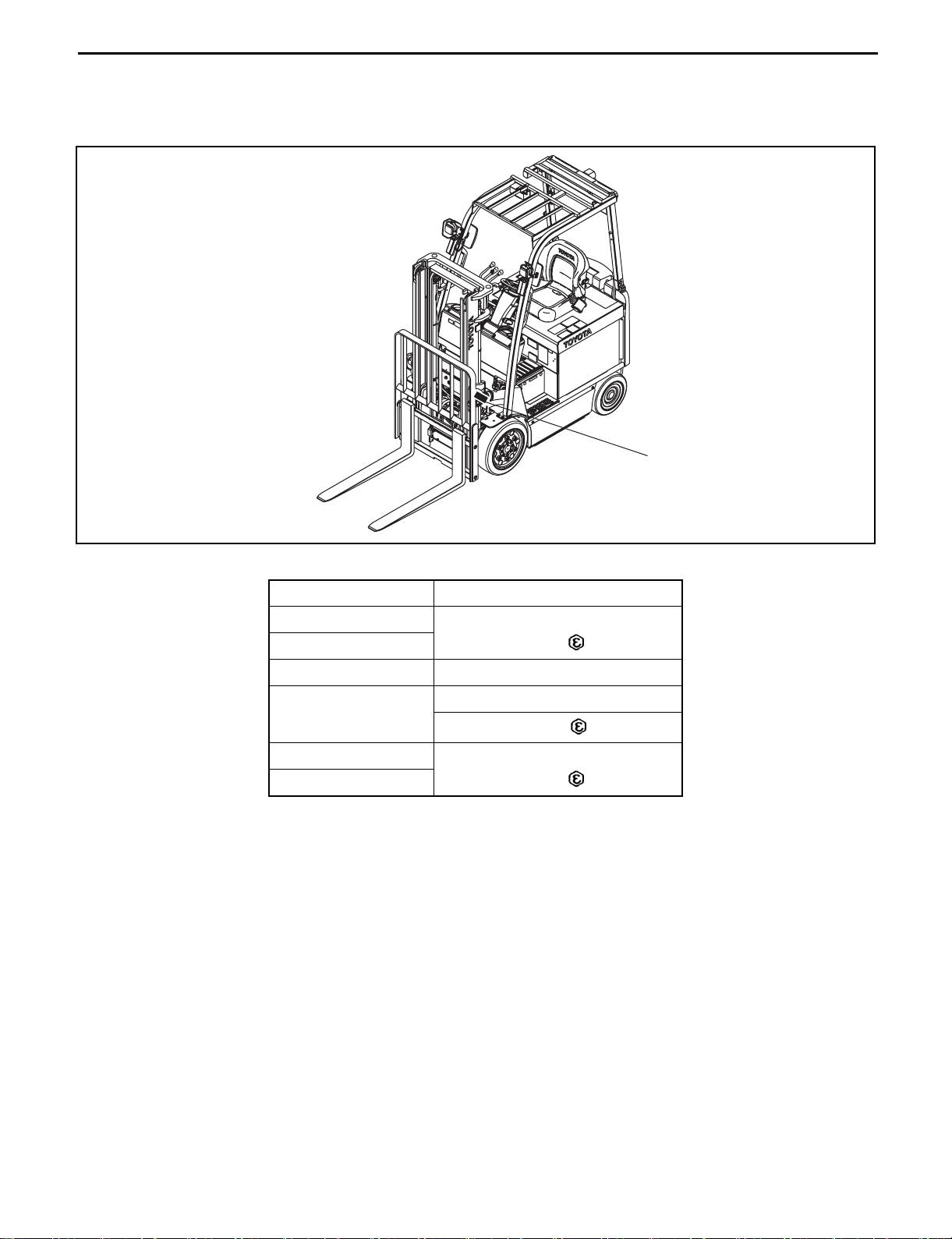
EXTERIOR VIEWS
0
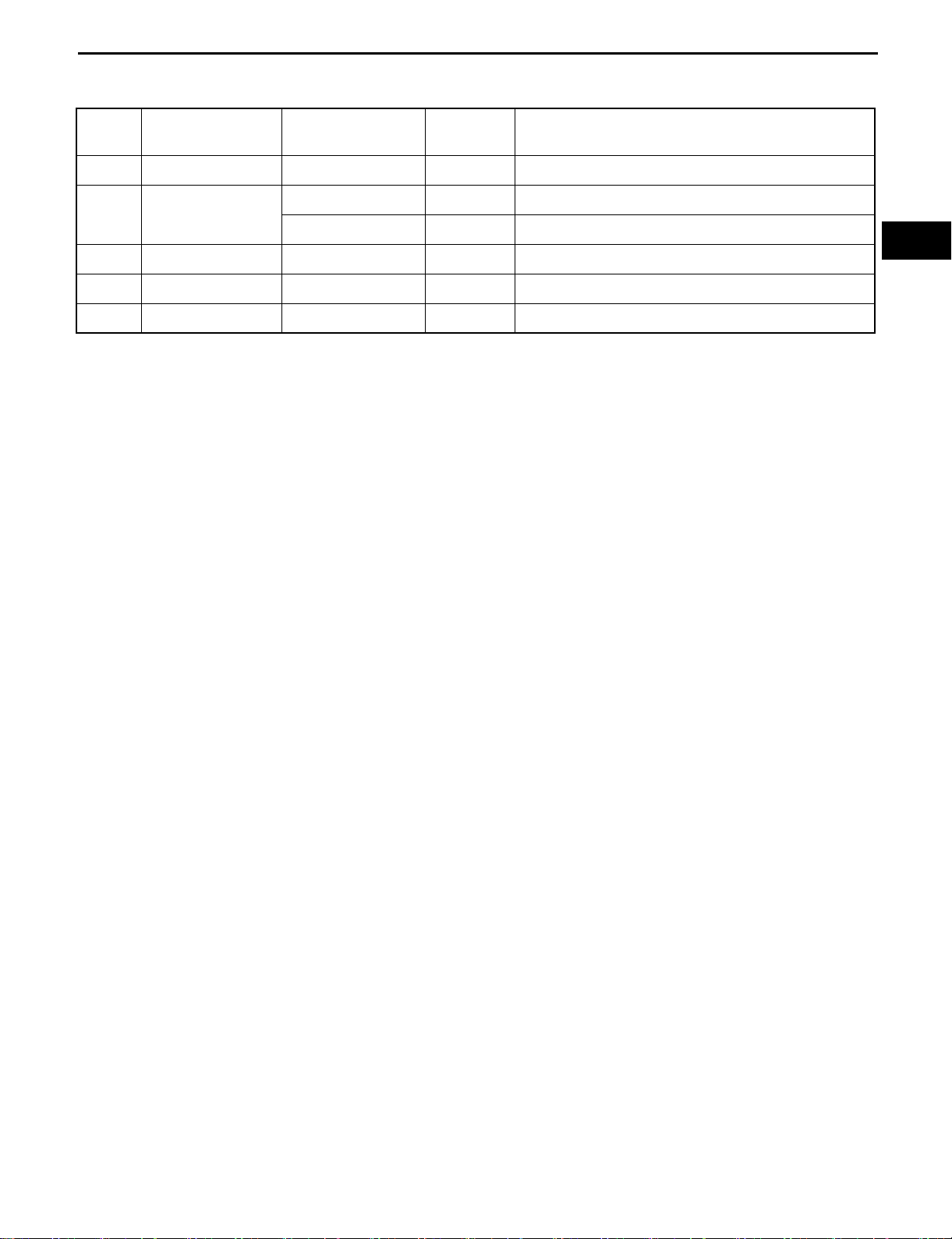
VEHICLE MODEL
0-3
Model
Code
20 4000 lbs 8FBCU20
25 5000 lbs
28 5500lbs 8FBCU28
30 6000 lbs 8FBCU30
32 6500 lbs 8FBCU32
Load Capacity Vehicle Model Voltage Remarks
8FBCU25
8FBCHU25
36V/48V
↑
↑
↑
↑
↑
0
USA·CANADA·MEXICO only
0-4
FRAME NUMBER
Frame No. Punching Position
Punching position
Vehicle Model Punching format
8FBCU20
8FBCU25
8FBCHU25 8FBCHU25-60011
8FBCU28
8FBCU30
8FBCU32
*: EEC spec.
* 8FBCU25 60011
* 8FBCU32 60011
8FBCU25-60011
8FBCU28-60011
* 8FBCU28 60011
8FBCU32-60011
HOW TO USE THIS MANUAL
EXPLANATION METHOD
1. Operation procedure
Example of description in pattern B
0-5
DISASSEMBLY·INSPECTION·REASSEMBLY
• Step Nos. are partially sometimes omitted in
illustrations.
• When a part requiring tightening torque
instruction is not indicated in the illustration,
the part name is described in the illustration
frame.
0
Tightening torque unit T = N·m (kgf·cm) [ft·lbf]
T = 46.1 to 48.1
(470 to 490)
[34.0 to 35.5]
Disassembly Procedure
1 Remove the cover. [Point 1]
2 Remove the bushing. [Point 2]
3 Remove the gear.
à Operation explained later
Point Operations
[Point 1]
Disassembly:
Put a match mark when removing the pump cover.
[Point 2]
Inspection:
Measure the bush inside diameter.
Limit: 19.12 mm (0.7528 in)
Explanation of key point for operation with an illustration
Ã

0-6
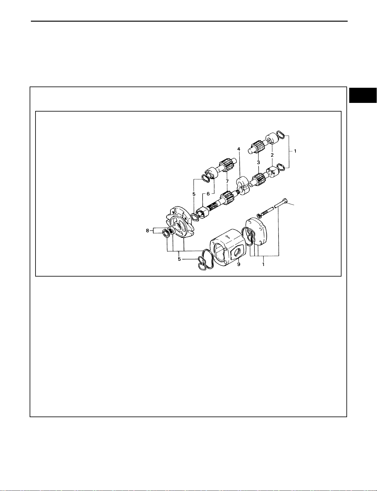
2. How to read components figures (Example)
(1) The components figure uses the illustration
in the parts catalog for the vehicle model.
Please refer to the catalog for checking the
part name.
The number at the right shoulder of each
components figure indicates the Fig.
number in the parts catalog.
(2) Refer to the parts catalog for the latest
information.
3. Matters omitted in this manual
This manual omits description of the following jobs, but perform them in actual operation:
(1) Cleaning and washing of removed parts as required
(2) Visual inspection (partially described)
FIG number in parts catalog
3201
TERMINOLOGY
Caution:
Important matters of which negligence may cause hazards on human body. Be sure to observe
them.
Note:
Important items of which negligence may cause breakage or breakdown, or matters in operation
procedure requiring special attention.
Standard: Values showing allowable range in inspection and adjustment.
Limit: Maximum or minimum allowable value in inspection or adjustment.
ABBREVIATIONS
Abbreviation (code) Meaning Abbreviation (code) Meaning
ASSY Assembly RR Rear
ATT Attachment SAE
Electronically controlled
EHPS
FHPS
LH Left hand SST Special service tool
FR Front STD Standard
OPS
fully hydraulic power
steering
Fully hydraulic power
steering
Operator Presence
Sensing
SAS System of active stability
SOL Solenoid
T= Tightening torque
Society of Automotive
Engineers (USA)
OPT Option {{T Number of teeth ({{)
O/S Oversize U/S Undersize
PS Power steering W/ With
RH Right hand L/ Less

0-7
SI UNITS
Meaning of SI
This manual uses SI units. SI represents the International System of Units, which was established to unify the various
systems of units used in the past for smoother international technical communication.
New Units Adopted in SI
Item New unit Conventional unit
2
Force*
*2
Torque
(Moment)
Pressure*
Revolving speed rpm rpm 1 rpm = 1 r/min
Spring constant*
Volume l cc 1 cc = 1 ml
Power W PS system 1 PS = 0.735499 kW
Heat quantity W·h cal 1 kcal = 1.16279 W·h
Specific fuel
consumption
2
↑↑mmHg 1 mmHg = 0.133322 kPa
2
N (newton) kgf 1 kgf = 9.80665 N
N·m kgf·cm 1 kgf·cm = 9.80665 N·m
Pa (pascal)
N/mm kgf/mm 1 kgf/mm = 9.80665 N/mm
g/W·h g/PS·h 1 g/PS·h = 1.3596 g/kW·h
kgf/cm
2
Conversion rate*
1 kgf/cm2 = 98.0665 kPa = 0.0980665 MPa
1
(1 [conventional unit] = X [SI unit])
<Reference>
* 1: X represents the value in SI units as converted from 1 [in conventional units], which can be used as the
rate for conversion between conventional and SI units.
* 2: In the past, kilogram [kg] representing mass was often used in place of weight kilogram [kgf], which
should be used as the unit of force.
Conversion between Conventional and SI Units
Equation for conversion
Value in SI unit = Conversion rate × Value in conventional unit
Value in conventional unit = Value in SI unit ÷ Conversion rate
Conversion rate: Figure corresponding to X in the
conversion rate column in the table above
When converting, change the unit of the value in conventional or SI units to the one in the conversion rate
column in the table above before calculation. For example, when converting 100 W to the value in
conventional unit PS, first change it to 0.1 kW and divide by the conversion rate 0.735499.
0-8
OPERATIONAL TIPS
1. Safe operation
(1) After jacking up, always support with wooden blocks or rigid stands.
(2) When hoisting the vehicle or its heavy component, use wire rope(s) with a sufficient reserve in load
capacity.
(3) Always disconnect the battery plug before the inspection or servicing of electrical parts.
2. Tactful operation
(1) Prepare the mechanic tools, necessary measuring instruments (circuit tester, megger, oil pressure
gauge, etc.) and SSTs before starting operation.
(2) Before disconnecting wiring, always check the cable color and wiring state.
(3) When overhauling functional parts, complicated portions or related mechanisms, arrange the parts
neatly to prevent confusion.
(4) When disassembling and inspecting such a precision part as the control valve, use clean tools and
operate in a clean location.
(5) Follow the described procedures for disassembly, inspection and reassembly.
(6) Replace, gaskets, packing and O-rings with new ones each time they are disassembled.
(7) Use genuine Toyota parts for replacement.
(8) Use specified bolts and nuts. Observe the specified tightening torque at the time of reassembly.
(Tighten to the center of the specified tightening torque range.)
If no tightening torque is specified, tighten the bolt or nut according to the standard tightening
torque table.
3. Protection of functional parts
(1) Thoroughly check each connector for any failure in or imperfect connection before reconnecting the
battery plug after the end of vehicle inspection or maintenance.
Failure in or imperfect connection of connectors related to controllers, especially, may
damage elements inside the controllers.
4. Confirming defect status
Do not start immediate disassembly or replacement, but first confirm if such disassembly or
replacement is actually needed.
5. Handling of waste fluid, etc.
When draining waste fluid from the vehicle, always receive it with an appropriate container.
Since careless or arbitrary discharge or disposal of oil, fuel, coolant, oil filter, battery or any other
harmful substance may cause adverse affect to people or environmental destruction, sort each waste
and always ask an authorized contractor for appropriate disposal.
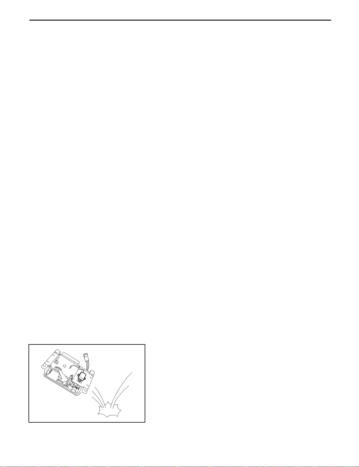
6. Handling of electronic parts
(1) Never apply impacts to electronic parts such as a
microcomputer or relay.
(2) Never let electronic parts be exposed to a high
temperature or humidity.
(3) Do not touch connector pins since they may be
deformed or be damaged due to static electricity.
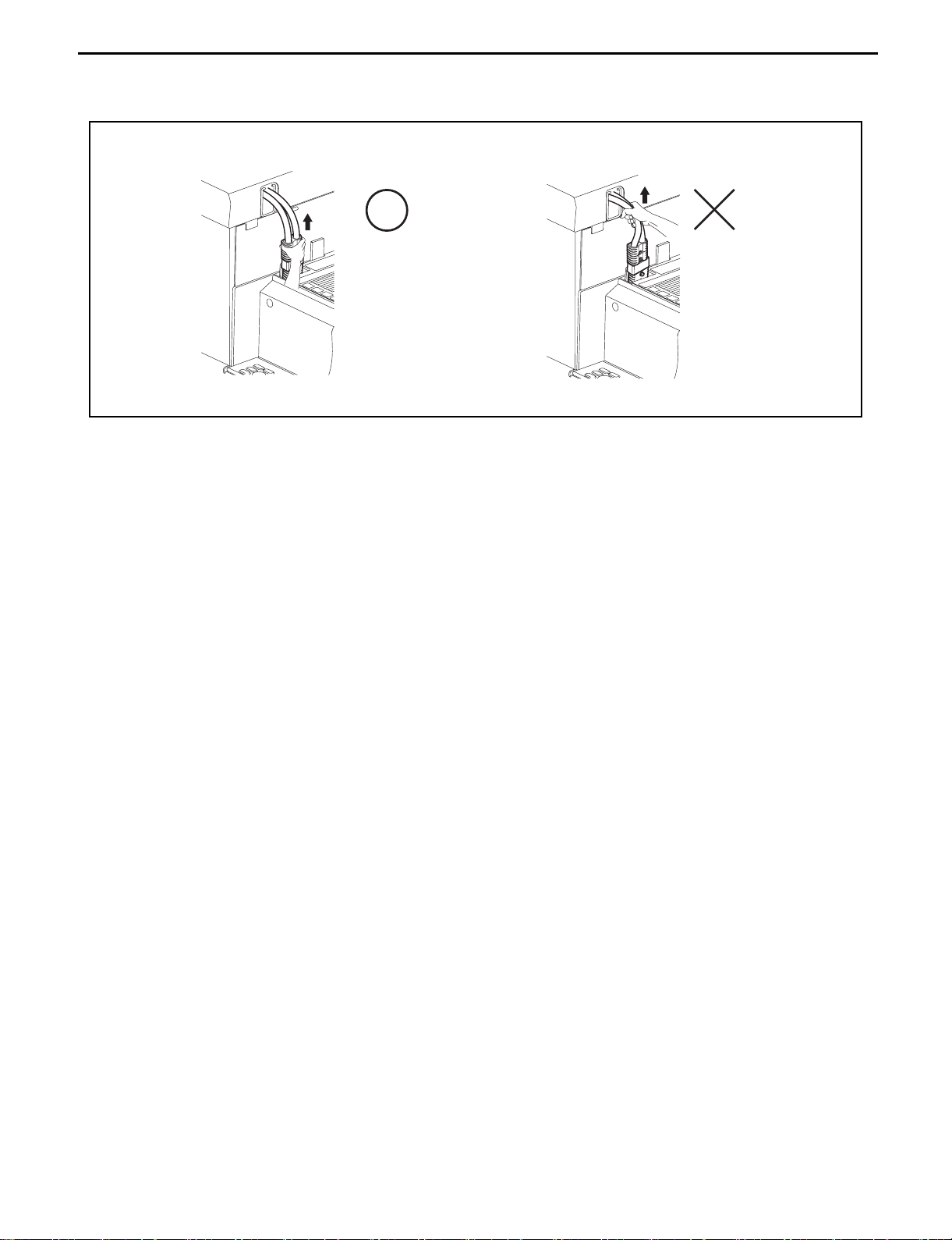
7. Disconnect the battery plug
When unplugging the battery plug, use the grip. Do not pull up the cable.
For example:
0-9
0-10
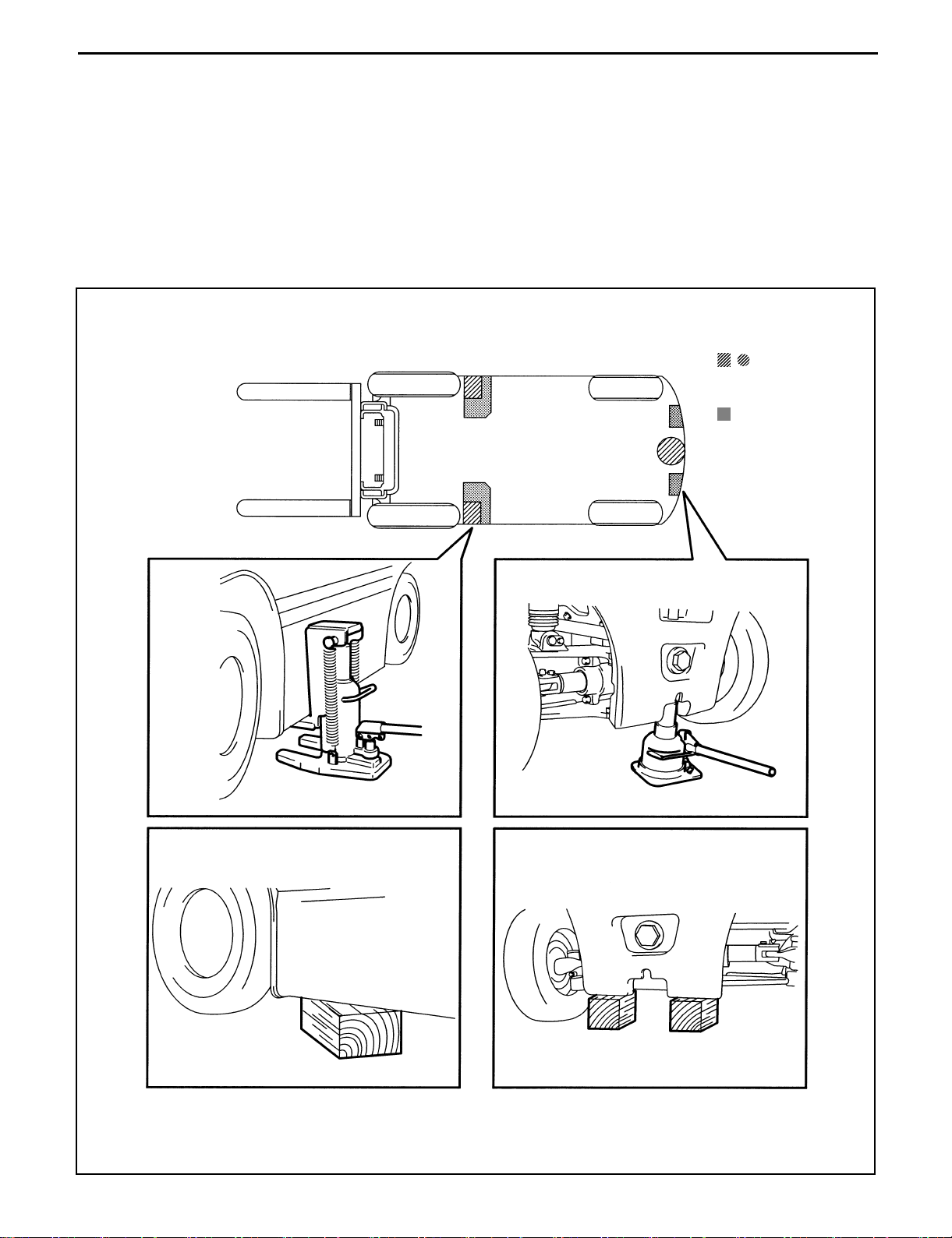
JACK-UP POINT
Strictly observe the following instructions when jacking up the vehicle.
• When a load is on the fork, unload it and park the vehicle on a flat floor. Be sure to avoid an inclined or
rugged place.
• Use a jack with ample capacity and jack up the vehicle at the specified jack-up point. Jacking up at any
other point will be dangerous.
• Never operate while the vehicle is held with a jack. Always support the frame with a wooden block after
jacking up.
• In any case, never let a part of the body (including hands and feet) be under the jacked-up vehicle.
:
Jack-up point
:
Wooden block or stand
setting point
0-11
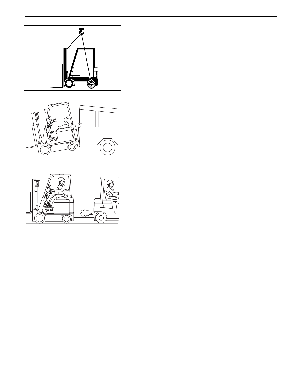
HOISTING THE VEHICLE
When hoisting the vehicle, use the mast hook on the front of
the vehicle and a wire net on the rear wheel.
Caution:
• Use wire ropes having sufficient strength.
• Never hoist the forklift by the weight hook holes or
head guard.
CAUTION FOR TOWING
1. When towing the forklift, always lift the rear wheels away
from the ground.
2. The traveling speed in towing must not exceed the
maximum traveling speed of the forklift.
3. Always set the key switch to OFF and the direction
switch to the neutral position before starting towing.
In case of towing by connection with a wire rope with the
operator on the forklift, however, set the key switch to
ON (PS operation) and always set the direction switch to
the neutral position.
4. Before towing, either remove the fork or take an action
to prevent fork contact with the ground due to bounding.
 Loading...