

Page 1

H SYSTEM CIRCUITS
2006 4RUNNER
ELECTRICAL WIRING DIAGRAM
SYSTEM CIRCUITS
ABS . . . . . . . . . . . . . . . . . . . . . . . . . . . . . . . . . . . . . . . . . . . . . . . . . . . . . . . . . . . . . . .
Active Height Control Suspension . . . . . . . . . . . . . . . . . . . . . . . . . . . . . . . . . . . 268
Air Conditioning . . . . . . . . . . . . . . . . . . . . . . . . . . . . . . . . . . . . . . . . . . . . . . . . . . . . 358
Audio System (w/ Navigation System) . . . . . . . . . . . . . . . . . . . . . . . . . . . . . . . . 334
Audio System (10 Speaker) . . . . . . . . . . . . . . . . . . . . . . . . . . . . . . . . . . . . . . . . . . 342
Audio System (6 Speaker) . . . . . . . . . . . . . . . . . . . . . . . . . . . . . . . . . . . . . . . . . . . 348
Auto LSD . . . . . . . . . . . . . . . . . . . . . . . . . . . . . . . . . . . . . . . . . . . . . . . . . . . . . . . . . . 258
Automatic Glare–Resistant EC Mirror with Compass . . . . . . . . . . . . . . . . . . . 302
Automatic Light Control . . . . . . . . . . . . . . . . . . . . . . . . . . . . . . . . . . . . . . . . . . . . . 140
Back–Up Light . . . . . . . . . . . . . . . . . . . . . . . . . . . . . . . . . . . . . . . . . . . . . . . . . . . . . . 174
Charging . . . . . . . . . . . . . . . . . . . . . . . . . . . . . . . . . . . . . . . . . . . . . . . . . . . . . . . . . . . 68
Cigarette Lighter . . . . . . . . . . . . . . . . . . . . . . . . . . . . . . . . . . . . . . . . . . . . . . . . . . . . 296
Combination Meter . . . . . . . . . . . . . . . . . . . . . . . . . . . . . . . . . . . . . . . . . . . . . . . . . . 352
Cruise Control (1GR–FE) . . . . . . . . . . . . . . . . . . . . . . . . . . . . . . . . . . . . . . . . . . . . 252
Cruise Control (2UZ–FE) . . . . . . . . . . . . . . . . . . . . . . . . . . . . . . . . . . . . . . . . . . . . 246
Door Lock Control . . . . . . . . . . . . . . . . . . . . . . . . . . . . . . . . . . . . . . . . . . . . . . . . . . 202
Downhill Assist Control . . . . . . . . . . . . . . . . . . . . . . . . . . . . . . . . . . . . . . . . . . . . . 258
Electric Modulated Air Suspension . . . . . . . . . . . . . . . . . . . . . . . . . . . . . . . . . . . 268
Electric Tension Reducer . . . . . . . . . . . . . . . . . . . . . . . . . . . . . . . . . . . . . . . . . . . . 306
Electronically Controlled Transmission and A/T Indicator (1GR–FE) . . . . 238
Electronically Controlled Transmission and A/T Indicator (2UZ–FE) . . . . . 230
Engine Control (1GR–FE) . . . . . . . . . . . . . . . . . . . . . . . . . . . . . . . . . . . . . . . . . . . . 84
Engine Control (2UZ–FE) . . . . . . . . . . . . . . . . . . . . . . . . . . . . . . . . . . . . . . . . . . . . 70
Engine Immobiliser System . . . . . . . . . . . . . . . . . . . . . . . . . . . . . . . . . . . . . . . . . . 98
Front Fog Light . . . . . . . . . . . . . . . . . . . . . . . . . . . . . . . . . . . . . . . . . . . . . . . . . . . . . 136
Front Wiper and Washer . . . . . . . . . . . . . . . . . . . . . . . . . . . . . . . . . . . . . . . . . . . . . 184
Garage Door Opener . . . . . . . . . . . . . . . . . . . . . . . . . . . . . . . . . . . . . . . . . . . . . . . . 182
Headlight . . . . . . . . . . . . . . . . . . . . . . . . . . . . . . . . . . . . . . . . . . . . . . . . . . . . . . . . . . 130
Hill–Start Assist Control . . . . . . . . . . . . . . . . . . . . . . . . . . . . . . . . . . . . . . . . . . . . . 258
Horn . . . . . . . . . . . . . . . . . . . . . . . . . . . . . . . . . . . . . . . . . . . . . . . . . . . . . . . . . . . . . . . 304
Ignition (1GR–FE) . . . . . . . . . . . . . . . . . . . . . . . . . . . . . . . . . . . . . . . . . . . . . . . . . . . 64
Ignition (2UZ–FE) . . . . . . . . . . . . . . . . . . . . . . . . . . . . . . . . . . . . . . . . . . . . . . . . . . . 60
Illumination . . . . . . . . . . . . . . . . . . . . . . . . . . . . . . . . . . . . . . . . . . . . . . . . . . . . . . . . 162
Interior Light . . . . . . . . . . . . . . . . . . . . . . . . . . . . . . . . . . . . . . . . . . . . . . . . . . . . . . . 154
Key Reminder . . . . . . . . . . . . . . . . . . . . . . . . . . . . . . . . . . . . . . . . . . . . . . . . . . . . . . 176
Light Auto Turn Off System . . . . . . . . . . . . . . . . . . . . . . . . . . . . . . . . . . . . . . . . . . 142
Mirror Heater . . . . . . . . . . . . . . . . . . . . . . . . . . . . . . . . . . . . . . . . . . . . . . . . . . . . . . . 330
Moon Roof . . . . . . . . . . . . . . . . . . . . . . . . . . . . . . . . . . . . . . . . . . . . . . . . . . . . . . . . . 288
Multi Mode 4WD . . . . . . . . . . . . . . . . . . . . . . . . . . . . . . . . . . . . . . . . . . . . . . . . . . . . 274
Multiplex Communication System (BEAN) . . . . . . . . . . . . . . . . . . . . . . . . . . . . 104
Multiplex Communication System (BEAN Bus) . . . . . . . . . . . . . . . . . . . . . . . . 100
Multiplex Communication System (CAN Bus) . . . . . . . . . . . . . . . . . . . . . . . . . 102
Navigation System . . . . . . . . . . . . . . . . . . . . . . . . . . . . . . . . . . . . . . . . . . . . . . . . . . 334
Power Outlet (115V) . . . . . . . . . . . . . . . . . . . . . . . . . . . . . . . . . . . . . . . . . . . . . . . . . 300
Power Outlet (12V) . . . . . . . . . . . . . . . . . . . . . . . . . . . . . . . . . . . . . . . . . . . . . . . . . . 298
Power Seat (Driver’s Seat w/ Driving Position Memory) . . . . . . . . . . . . . . . . 308
Power Seat (Driver’s Seat w/o Driving Position Memory) . . . . . . . . . . . . . . . 312
Page
258
52
4RUNNER (EM00T0U)
Page 2
H
Page
Power Seat (Front Passenger’s Seat) . . . . . . . . . . . . . . . . . . . . . . . . . . . . . . . . .
Power Source . . . . . . . . . . . . . . . . . . . . . . . . . . . . . . . . . . . . . . . . . . . . . . . . . . . . . . 54
Power Window . . . . . . . . . . . . . . . . . . . . . . . . . . . . . . . . . . . . . . . . . . . . . . . . . . . . . 192
Rear Window Defogger . . . . . . . . . . . . . . . . . . . . . . . . . . . . . . . . . . . . . . . . . . . . . . 330
Rear Wiper and Washer . . . . . . . . . . . . . . . . . . . . . . . . . . . . . . . . . . . . . . . . . . . . . 186
Remote Control Mirror . . . . . . . . . . . . . . . . . . . . . . . . . . . . . . . . . . . . . . . . . . . . . . 294
Seat Belt Warning . . . . . . . . . . . . . . . . . . . . . . . . . . . . . . . . . . . . . . . . . . . . . . . . . . . 178
Seat Heater . . . . . . . . . . . . . . . . . . . . . . . . . . . . . . . . . . . . . . . . . . . . . . . . . . . . . . . . . 318
Shift Lock . . . . . . . . . . . . . . . . . . . . . . . . . . . . . . . . . . . . . . . . . . . . . . . . . . . . . . . . . . 292
SRS . . . . . . . . . . . . . . . . . . . . . . . . . . . . . . . . . . . . . . . . . . . . . . . . . . . . . . . . . . . . . . . 281
Starting . . . . . . . . . . . . . . . . . . . . . . . . . . . . . . . . . . . . . . . . . . . . . . . . . . . . . . . . . . . . 58
Stop Light . . . . . . . . . . . . . . . . . . . . . . . . . . . . . . . . . . . . . . . . . . . . . . . . . . . . . . . . . . 170
T aillight . . . . . . . . . . . . . . . . . . . . . . . . . . . . . . . . . . . . . . . . . . . . . . . . . . . . . . . . . . . . 162
Theft Deterrent . . . . . . . . . . . . . . . . . . . . . . . . . . . . . . . . . . . . . . . . . . . . . . . . . . . . . 222
Tire Pressure Warning System . . . . . . . . . . . . . . . . . . . . . . . . . . . . . . . . . . . . . . . 326
TOYOT A Parking Assist (Rear View Monitor) . . . . . . . . . . . . . . . . . . . . . . . . . . 334
TRAC . . . . . . . . . . . . . . . . . . . . . . . . . . . . . . . . . . . . . . . . . . . . . . . . . . . . . . . . . . . . . . 258
Trailer T owing . . . . . . . . . . . . . . . . . . . . . . . . . . . . . . . . . . . . . . . . . . . . . . . . . . . . . . 322
Turn Signal and Hazard Warning Light (w/ Daytime Running Light) . . . . . 146
Turn Signal and Hazard Warning Light (w/o Daytime Running Light) . . . . 150
VSC . . . . . . . . . . . . . . . . . . . . . . . . . . . . . . . . . . . . . . . . . . . . . . . . . . . . . . . . . . . . . . . 258
Wireless Door Lock Control . . . . . . . . . . . . . . . . . . . . . . . . . . . . . . . . . . . . . . . . . 212
316
4RUNNER (EM00T0U)
53
Page 3
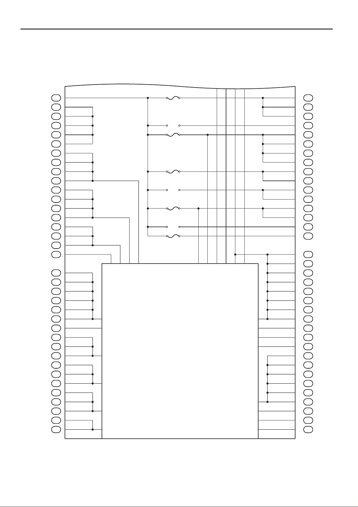
F RELAY LOCATIONS
t
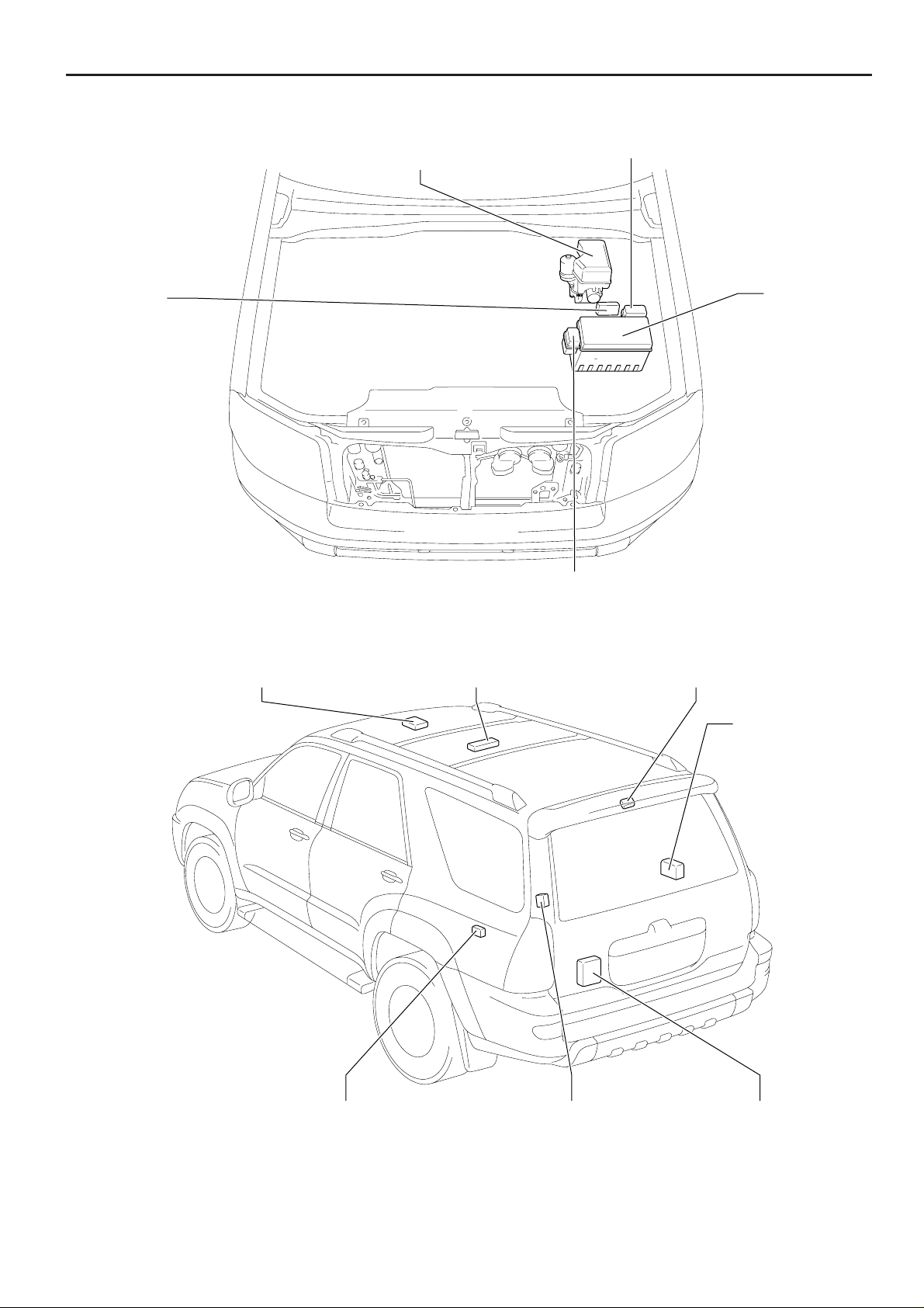
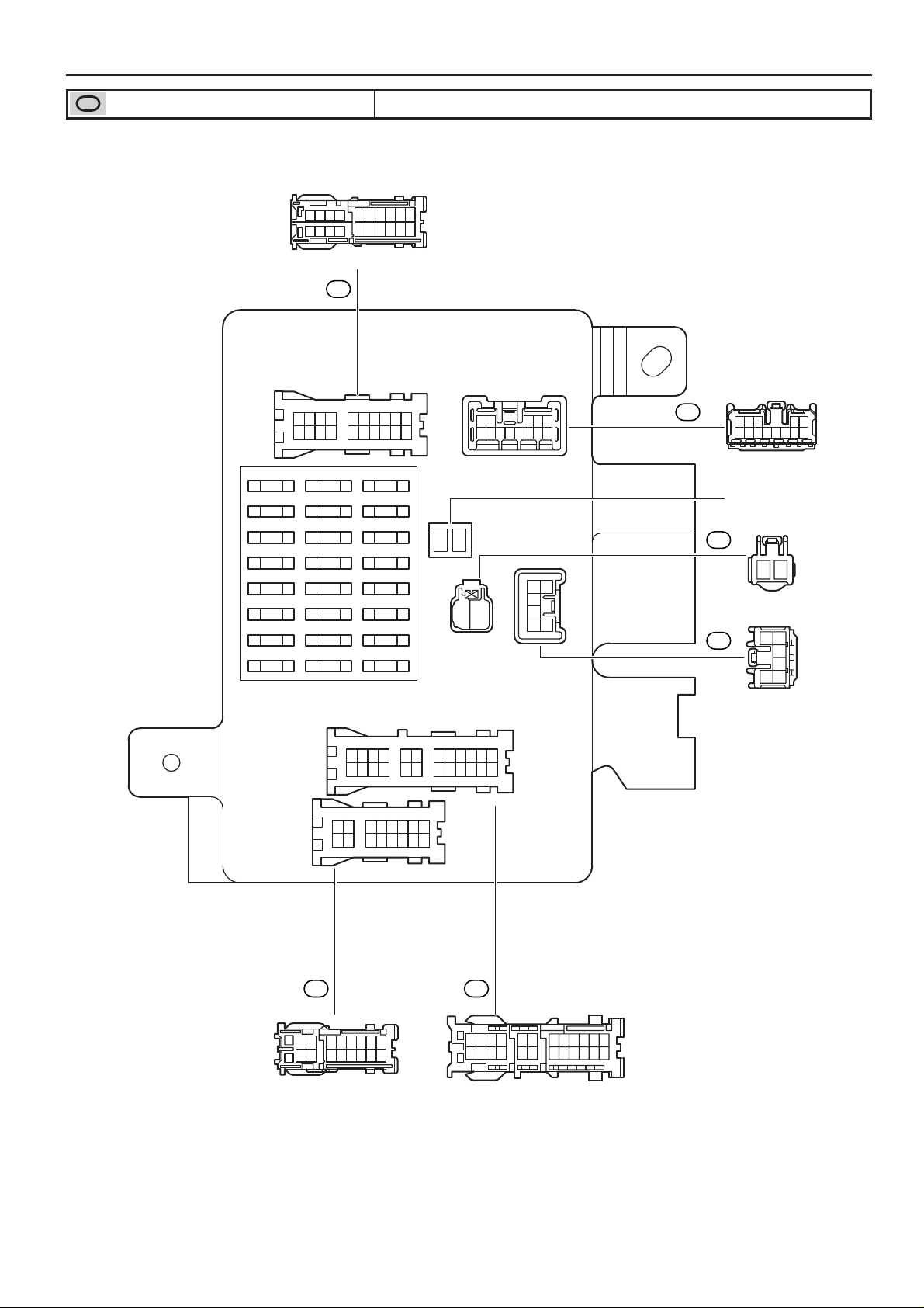
[Engine Compartment]
Engine Room R/B No.3Skid Control ECU
with Actuator
Air Injection
Control Driver
[Body]
Engine Room
R/B
Engine Room R/B No.4
Rear Seat Audio Controller Tire Pressure Monitor ReceiverMoon Roof Control ECU
Stereo Componen
Amplifier
20
Towing Converter Relay
4RUNNER (EM00T0U)
Door Control Receiver Back Door ECU
Page 4
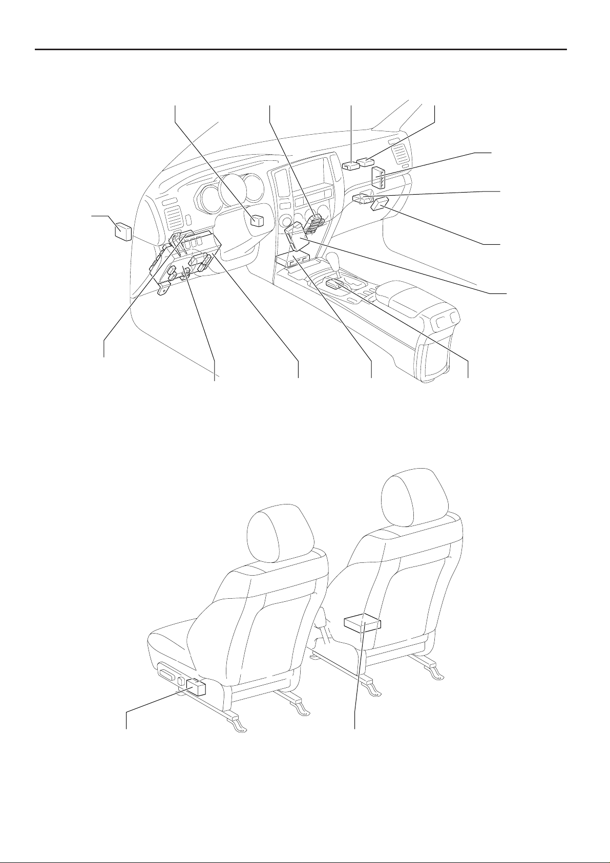
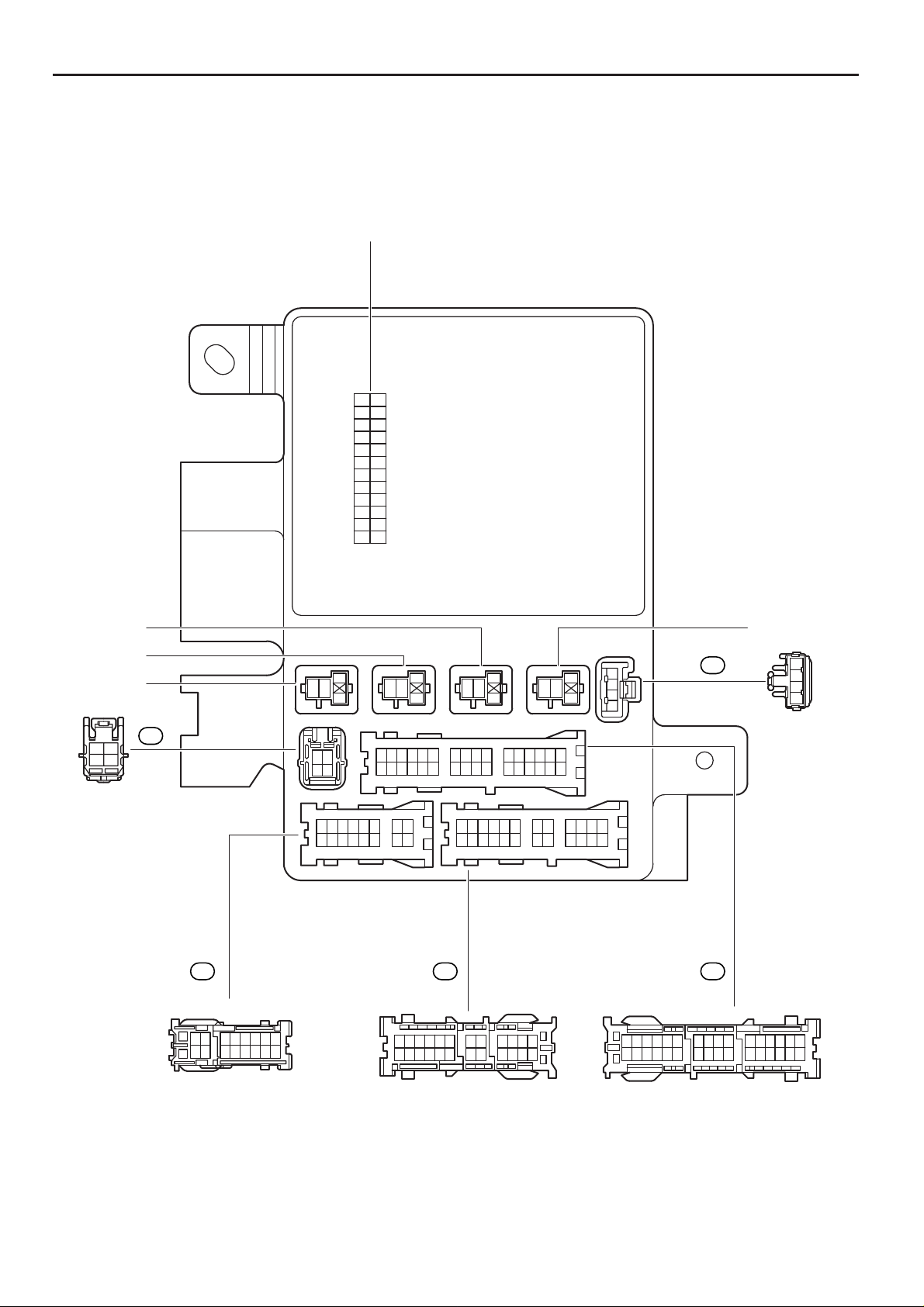
[Instrument Panel]
F
Suspension
Control ECU
Turn Signal
Flasher Relay
Daytime Running
Light Relay
Transponder Key
Amplifier
Driver Side J/B
Center J/B
Body ECU
Theft Deterrent
ECU
Airbag Sensor
Assembly
Transponder Key
Computer
Engine Control
Module
4WD Control
ECU
Tire Pressure
Monitor ECU
A/C Control
Assembly
Shift Lock
Control ECU
[Seat]
ECU and SW
Occupant Classification ECUPosition Control
21
4RUNNER (EM00T0U)
Page 5
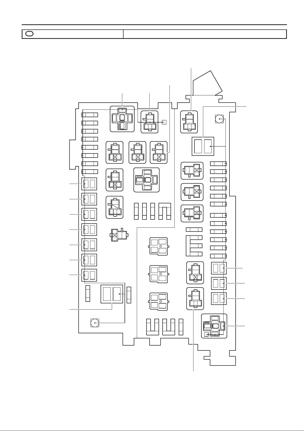
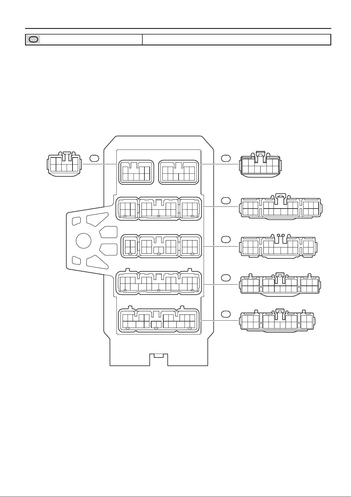
F RELAY LOCATIONS
2
: Engine Room R/B Engine Compartment Left (See Page 20)
* 1:ACC CUT Relay
* 2:FR FOG Relay
* 3:STA Relay
* 4:HEATER Relay
* 5:MG CLT Relay
* 6:RADIO NO.1
* 7:C/OPN Relay
* 8:DOME Relay
* 9:EFI Relay
* 10:A/F HEATER Relay
* 11:HEAD (LO LH)
* 12:HEAD (HI LH)
40A TOWING
(for High Current)
30A BATT CHG
(for High Current)
50A J/B
(for High Current)
30A TOWING BRK
(for High Current)
50A AM1
(for High Current)
50A AIR SUS
(for High Current)
50A A/PUMP
(for High Current)
140A ALT
(for High Current)
7.5A
12
OBD
15A
12
FR FOG
15A
12
AC115V INV
10A
12
STOP
*3
*2 *4
21
1
2
*1
21
21
21
21
21
IG Relay DEFOG Relay
5
21
3
*5
3
5
12
354
12
7.5A
AIRSUS NO.2
HEATER NO.2
3
5
12
3
5
1
2
4321
12
AC115V INV Relay
3
5
42
1
3
5
12
2
1
12
12
1
10A
25A
30A
DEFOG
2
SEAT HEATER
10A 2
HEAD (LO RH)
*11
212
10A
MIR HEATER
10A
HEAD (HI RH)
FUEL PUMP Relay
3
5
2
14
35
*10
35
*9
10A
2
*12
1
2
10A
*8
*7
2
10A
EFI NO.2
1
5
3
ECU-B
10A 2
*6
20A12
DOME
10A 2
3
5
12
3
5
142
21
RADIO NO.2
2
1
2
1
2
1
A/F HEATER
3
20A21
TOWING
30A21
DR/LCK
20A21
EFI
20A21
ETCS
10A21
TRN-HAZ
15A21
15A21
HORN
10A21
ALT-S
7.5A21
Short Pin
221
1
1
2
1
2
2
5
1
60A HEATER
(for High Current)
30A ABS SOL
(for High Current)
30A AM2
(for High Current)
40A ABS MTR
(for High Current)
HEAD Relay
22
STOP LP CTRL Relay
4RUNNER (EM00T0U)
Page 6
3
: Engine Room R/B No.3 Engine Compartment Left (See Page 20)
F
3
12
5
TOWING TAIL RelayBATT CHG Relay
4
: Engine Room R/B No.4 Engine Compartment Left (See Page 20)
3
12
5
3
12
5
AIR SUS Relay
4RUNNER (EM00T0U)
23
Page 7
F RELAY LOCATIONS
: Driver Side J/B Lower Finish Panel (See Page 21)
4WD
20A
FR WIP-WSH
30A
STA NO.2
7.5A
GAUGE
7.5A
SRS
10A
IGN
10A
20191817
10987
161514 131211
654321
(from Roof Wire)
1A
910
654321
87
1920 161514 13 12 111817
IG1
15A
ECU-IG
10A
RR WSH
15A
PWR OUTLET
15A
P P/SEAT
30A
D P/SEAT
30A
SECU/HORN
CIG
10A
ACC
7.5A
TAIL
10A
10A
12
21
12345
678910111213
1B
123 45
6 7 8 9 10111213
(from Engine Room Main Wire)
30A POWER
(for Medium Current)
1C
12
216
5
4
3
(from Engine Room Main Wire)
1D
6
5
4
123
(from Engine Room Main Wire)
9101112 87 654321
21222324 2019 181716 15 14 13
78 65432
1516 141312 11 10
1
9
1F 1E
1516
78152364
913 101114 12
(from Floor No.2 Wire)
1817 161514132019242322 21
65432187121110 9
(from Engine Room Main Wire)
24
4RUNNER (EM00T0U)
Page 8
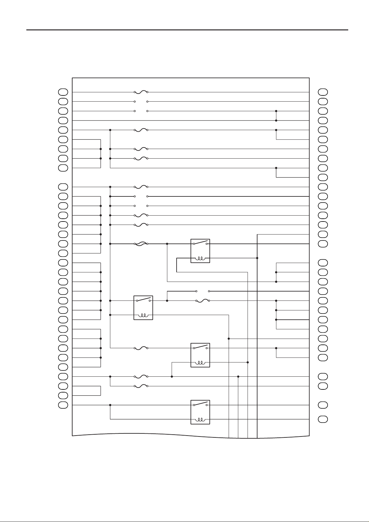
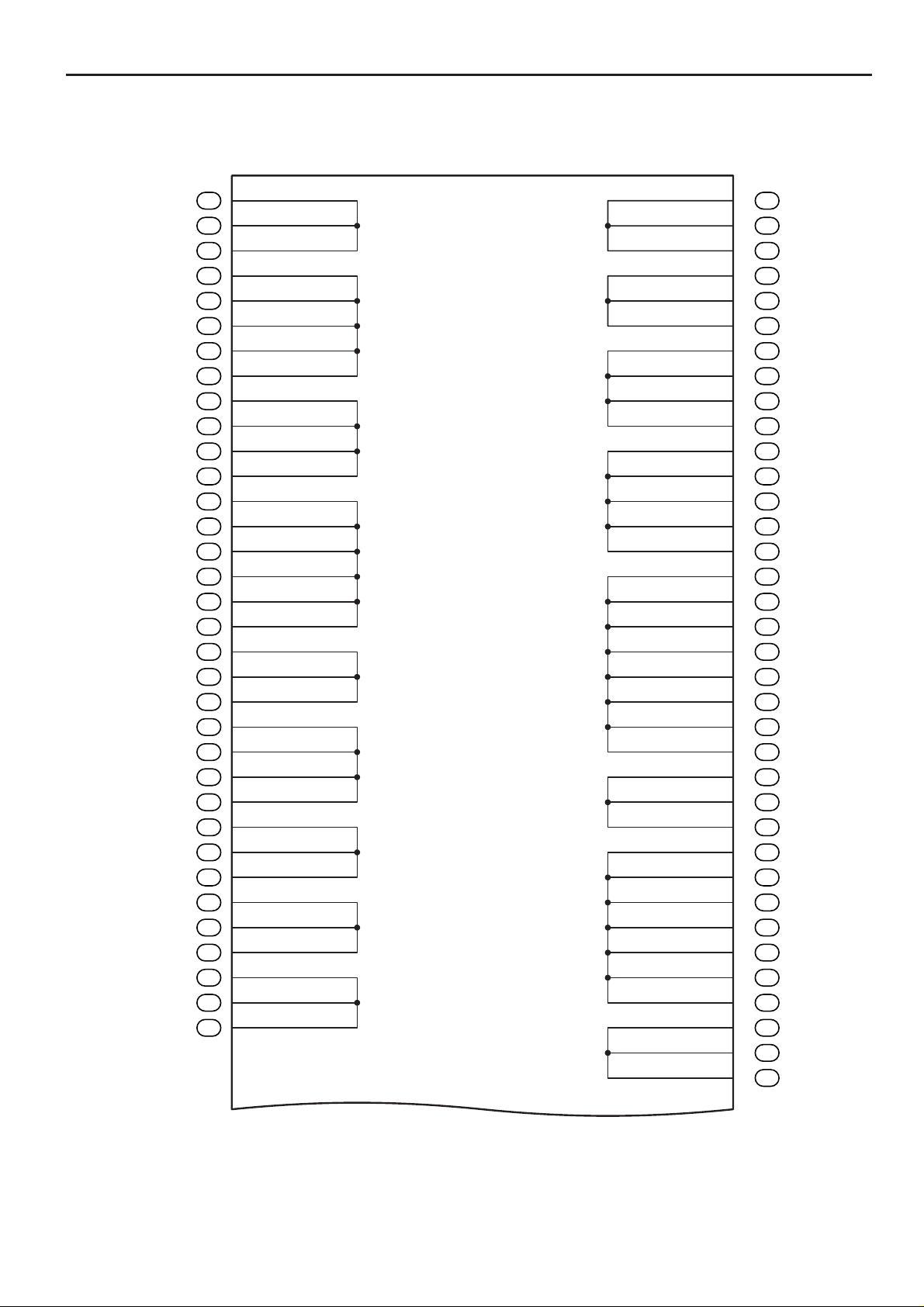
Body ECU
1
13
2
14
3
15
4
16
5
17
6
18
7
19
8
20
9
21
10
22
11
23
12
24
F
POWER Relay
TAIL Relay
HORN Relay
1H
12
34
(from Instrument
Panel Wire)
35
21
9
1
2
1
34
35
15161413121110
7865432
2
1
222120191817
654321
35
25262423
91087
2
1
35
323130292827
161514131211
4
2
3
2
1
1
2122 23242019181716151413
910111287654321
1K 1L 1J
1615 14 10131211
87 6 254 13
9
871211109
654321
181716151413 2019 24232221
1G
DC SKT Relay
4
3
2
1
(from Instrument
Panel Wire)
17181920212223242526272829303132
12345678910111213141516
(from Instrument Panel Wire)
(from Instrument Panel Wire) (from Instrument Panel Wire)
25
4RUNNER (EM00T0U)
Page 9
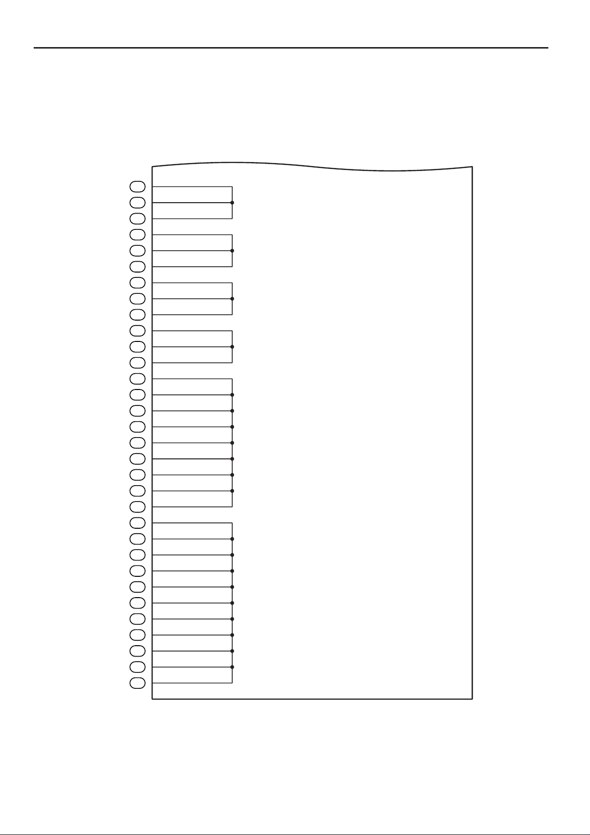
F RELAY LOCATIONS
[Driver Side J/B Inner Circuit]
13
10
10
23
24
17
18
15
22
19
10
10
3
1D
1L
4
1D
1J
6
1D
2
1L
1
1J
2
1J
1F
1
1C
1J
7
1E
8
1E
1J
2
1G
1
1L
9
1F
5
1J
1E
1E
6
1J
3
1G
4
1J
1F
6
1E
1J
9
1A
4
1A
1A
5
1D
3
1E
1A
1E
7.5A STA NO.2
10A IGN
7.5A GAUGE
10A SRS
10A SECU/HORN
30A P P/SEAT
30A D P/SEAT
30A POWER
15
TAIL Relay
5
1
15A PWR OUTLET
7.5A ACC
23
3
2
10A CIG
POWER Relay
2
10A TAIL
DC SKT Relay
3
1
HORN Relay
5
1
5
2
3
21
15
23
11
20
10
12
14
32
29
25
11
21
11
13
16
30
31
17
2
1K
4
1K
1E
1L
1E
1J
4
1G
1L
3
1H
4
1H
1K
1K
1K
1J
1J
1
1A
1
1H
1J
2
1F
1A
1J
9
1B
1B
5
1L
1F
1E
1J
1J
8
1K
1L
1
1D
26
1
2
(Cont. Next Page)
4RUNNER (EM00T0U)
13
1K
Page 10
(Cont'd)
F
17
18
20
15
16
16
12
14
15
16
18
21
22
23
24
11
16
24
12
16
26
2
1C
1
1E
2
1E
1J
1J
1J
1K
1L
1K
4
1F
4
1B
5
1B
4
1L
1F
1J
1J
1J
6
1B
1L
1L
1L
1L
1L
6
1F
8
1B
1
1G
1K
5
1A
9
1K
8
1A
1A
1E
1J
1F
9
1E
1J
7 8 11 5 1 10 18 22 4
BZR2
BECU
24
17
14
13
12
3
HAZ
ACTHRLY
SPD
ILE
STPI
BDR1
LSR
15A IG1
10A ECU-IG
30A FR WIP-WSH
15A RR WSH
20A 4WD
Body ECU
WIG
SIG
TRLY
ACC
GND1
21
PWS
GND2
WMTR
L1
L2
UL1
ACT+
RDEF
BZR
16
19
20
15
23
2
6
9
20
12
28
22
11
12
13
13
12
15
13
14
18
10
11
12
14
10
1E
8
1J
2
1A
7
1K
1E
1J
8
1F
3
1A
1E
9
1J
3
1L
1F
1B
1B
6
1K
1J
2
1H
1A
1A
1A
7
1A
6
1A
1A
1A
5
1K
3
1K
1
1K
6
1L
9
1L
1L
1L
1L
1F
1
1B
3
1B
1B
4RUNNER (EM00T0U)
27
Page 11
F RELAY LOCATIONS
: Center J/B Instrument Panel Brace RH (See Page 21)
Black
AA A
BBBBB
3A 3B
(from Instrument Panel Wire)
AAA
BBBBB
AA
BBBBB
AAAA
BBBBBB
B
(from Instrument Panel Wire)
AA
Gray
AAABBBBCCC
3C
DDDEEEFFFGGG
AAABB BBCC
DDD EE E F FF GGG
C
(from Instrument Panel Wire)
Black
AAAAABBBB
CCCDDDDDDDD
3D
AAAAA BBBB
CCC DD D D DD DD
(from Instrument Panel Wire)
Dark Gray
AAABBBBBBB
CCCDDDEEEFFF
3E
AAA
CCCBDBDDEE
BBEBBB
FFF
(from Instrument Panel Wire)
AAAAAAAAA
BBBBBBBBBBB
3F
AAA
BBBABABBBB
AABAA
BB
28
(from Instrument Panel Wire)
4RUNNER (EM00T0U)
Page 12

Memo
4RUNNER (EM00T0U)
29
Page 13
F RELAY LOCATIONS
[Center J/B Inner Circuit]
A
3A
A
3A
A
3A
B
3A
B
3A
B
3A
B
3A
B
3A
A
3B
A
3B
A
3B
A
3B
B
3B
B
3B
B
3B
B
3B
B
3B
B
3B
C
3C
C
3C
C
3C
B
3C
B
3C
B
3C
B
3C
A
3C
A
3C
A
3C
F
3C
F
3C
F
3C
G
3C
G
3C
G
3C
E
3C
E
3C
E
3C
D
3C
D
3C
D
3C
B
3D
B
3D
B
3D
B
3D
A
3D
A
3D
A
3D
A
3D
A
3D
D
3D
D
3D
D
3D
D
3D
D
3D
D
3D
D
3D
D
3D
C
3D
C
3D
C
3D
B
3E
B
3E
B
3E
B
3E
B
3E
B
3E
B
3E
A
3E
A
3E
A
3E
30
(Cont. Next Page)
4RUNNER (EM00T0U)
Page 14
F
(Cont'd)
F
3E
F
3E
F
3E
E
3E
E
3E
E
3E
D
3E
D
3E
D
3E
C
3E
C
3E
C
3E
A
3F
A
3F
A
3F
A
3F
A
3F
A
3F
A
3F
A
3F
A
3F
B
3F
B
3F
B
3F
B
3F
B
3F
B
3F
B
3F
B
3F
B
3F
B
3F
B
3F
4RUNNER (EM00T0U)
31
Page 15
H SYSTEM CIRCUITS
2006 4RUNNER
ELECTRICAL WIRING DIAGRAM
SYSTEM CIRCUITS
ABS . . . . . . . . . . . . . . . . . . . . . . . . . . . . . . . . . . . . . . . . . . . . . . . . . . . . . . . . . . . . . . .
Active Height Control Suspension . . . . . . . . . . . . . . . . . . . . . . . . . . . . . . . . . . . 268
Air Conditioning . . . . . . . . . . . . . . . . . . . . . . . . . . . . . . . . . . . . . . . . . . . . . . . . . . . . 358
Audio System (w/ Navigation System) . . . . . . . . . . . . . . . . . . . . . . . . . . . . . . . . 334
Audio System (10 Speaker) . . . . . . . . . . . . . . . . . . . . . . . . . . . . . . . . . . . . . . . . . . 342
Audio System (6 Speaker) . . . . . . . . . . . . . . . . . . . . . . . . . . . . . . . . . . . . . . . . . . . 348
Auto LSD . . . . . . . . . . . . . . . . . . . . . . . . . . . . . . . . . . . . . . . . . . . . . . . . . . . . . . . . . . 258
Automatic Glare–Resistant EC Mirror with Compass . . . . . . . . . . . . . . . . . . . 302
Automatic Light Control . . . . . . . . . . . . . . . . . . . . . . . . . . . . . . . . . . . . . . . . . . . . . 140
Back–Up Light . . . . . . . . . . . . . . . . . . . . . . . . . . . . . . . . . . . . . . . . . . . . . . . . . . . . . . 174
Charging . . . . . . . . . . . . . . . . . . . . . . . . . . . . . . . . . . . . . . . . . . . . . . . . . . . . . . . . . . . 68
Cigarette Lighter . . . . . . . . . . . . . . . . . . . . . . . . . . . . . . . . . . . . . . . . . . . . . . . . . . . . 296
Combination Meter . . . . . . . . . . . . . . . . . . . . . . . . . . . . . . . . . . . . . . . . . . . . . . . . . . 352
Cruise Control (1GR–FE) . . . . . . . . . . . . . . . . . . . . . . . . . . . . . . . . . . . . . . . . . . . . 252
Cruise Control (2UZ–FE) . . . . . . . . . . . . . . . . . . . . . . . . . . . . . . . . . . . . . . . . . . . . 246
Door Lock Control . . . . . . . . . . . . . . . . . . . . . . . . . . . . . . . . . . . . . . . . . . . . . . . . . . 202
Downhill Assist Control . . . . . . . . . . . . . . . . . . . . . . . . . . . . . . . . . . . . . . . . . . . . . 258
Electric Modulated Air Suspension . . . . . . . . . . . . . . . . . . . . . . . . . . . . . . . . . . . 268
Electric Tension Reducer . . . . . . . . . . . . . . . . . . . . . . . . . . . . . . . . . . . . . . . . . . . . 306
Electronically Controlled Transmission and A/T Indicator (1GR–FE) . . . . 238
Electronically Controlled Transmission and A/T Indicator (2UZ–FE) . . . . . 230
Engine Control (1GR–FE) . . . . . . . . . . . . . . . . . . . . . . . . . . . . . . . . . . . . . . . . . . . . 84
Engine Control (2UZ–FE) . . . . . . . . . . . . . . . . . . . . . . . . . . . . . . . . . . . . . . . . . . . . 70
Engine Immobiliser System . . . . . . . . . . . . . . . . . . . . . . . . . . . . . . . . . . . . . . . . . . 98
Front Fog Light . . . . . . . . . . . . . . . . . . . . . . . . . . . . . . . . . . . . . . . . . . . . . . . . . . . . . 136
Front Wiper and Washer . . . . . . . . . . . . . . . . . . . . . . . . . . . . . . . . . . . . . . . . . . . . . 184
Garage Door Opener . . . . . . . . . . . . . . . . . . . . . . . . . . . . . . . . . . . . . . . . . . . . . . . . 182
Headlight . . . . . . . . . . . . . . . . . . . . . . . . . . . . . . . . . . . . . . . . . . . . . . . . . . . . . . . . . . 130
Hill–Start Assist Control . . . . . . . . . . . . . . . . . . . . . . . . . . . . . . . . . . . . . . . . . . . . . 258
Horn . . . . . . . . . . . . . . . . . . . . . . . . . . . . . . . . . . . . . . . . . . . . . . . . . . . . . . . . . . . . . . . 304
Ignition (1GR–FE) . . . . . . . . . . . . . . . . . . . . . . . . . . . . . . . . . . . . . . . . . . . . . . . . . . . 64
Ignition (2UZ–FE) . . . . . . . . . . . . . . . . . . . . . . . . . . . . . . . . . . . . . . . . . . . . . . . . . . . 60
Illumination . . . . . . . . . . . . . . . . . . . . . . . . . . . . . . . . . . . . . . . . . . . . . . . . . . . . . . . . 162
Interior Light . . . . . . . . . . . . . . . . . . . . . . . . . . . . . . . . . . . . . . . . . . . . . . . . . . . . . . . 154
Key Reminder . . . . . . . . . . . . . . . . . . . . . . . . . . . . . . . . . . . . . . . . . . . . . . . . . . . . . . 176
Light Auto Turn Off System . . . . . . . . . . . . . . . . . . . . . . . . . . . . . . . . . . . . . . . . . . 142
Mirror Heater . . . . . . . . . . . . . . . . . . . . . . . . . . . . . . . . . . . . . . . . . . . . . . . . . . . . . . . 330
Moon Roof . . . . . . . . . . . . . . . . . . . . . . . . . . . . . . . . . . . . . . . . . . . . . . . . . . . . . . . . . 288
Multi Mode 4WD . . . . . . . . . . . . . . . . . . . . . . . . . . . . . . . . . . . . . . . . . . . . . . . . . . . . 274
Multiplex Communication System (BEAN) . . . . . . . . . . . . . . . . . . . . . . . . . . . . 104
Multiplex Communication System (BEAN Bus) . . . . . . . . . . . . . . . . . . . . . . . . 100
Multiplex Communication System (CAN Bus) . . . . . . . . . . . . . . . . . . . . . . . . . 102
Navigation System . . . . . . . . . . . . . . . . . . . . . . . . . . . . . . . . . . . . . . . . . . . . . . . . . . 334
Power Outlet (115V) . . . . . . . . . . . . . . . . . . . . . . . . . . . . . . . . . . . . . . . . . . . . . . . . . 300
Power Outlet (12V) . . . . . . . . . . . . . . . . . . . . . . . . . . . . . . . . . . . . . . . . . . . . . . . . . . 298
Power Seat (Driver’s Seat w/ Driving Position Memory) . . . . . . . . . . . . . . . . 308
Power Seat (Driver’s Seat w/o Driving Position Memory) . . . . . . . . . . . . . . . 312
Page
258
52
4RUNNER (EM00T0U)
Page 16

H
Page
Power Seat (Front Passenger’s Seat) . . . . . . . . . . . . . . . . . . . . . . . . . . . . . . . . .
Power Source . . . . . . . . . . . . . . . . . . . . . . . . . . . . . . . . . . . . . . . . . . . . . . . . . . . . . . 54
Power Window . . . . . . . . . . . . . . . . . . . . . . . . . . . . . . . . . . . . . . . . . . . . . . . . . . . . . 192
Rear Window Defogger . . . . . . . . . . . . . . . . . . . . . . . . . . . . . . . . . . . . . . . . . . . . . . 330
Rear Wiper and Washer . . . . . . . . . . . . . . . . . . . . . . . . . . . . . . . . . . . . . . . . . . . . . 186
Remote Control Mirror . . . . . . . . . . . . . . . . . . . . . . . . . . . . . . . . . . . . . . . . . . . . . . 294
Seat Belt Warning . . . . . . . . . . . . . . . . . . . . . . . . . . . . . . . . . . . . . . . . . . . . . . . . . . . 178
Seat Heater . . . . . . . . . . . . . . . . . . . . . . . . . . . . . . . . . . . . . . . . . . . . . . . . . . . . . . . . . 318
Shift Lock . . . . . . . . . . . . . . . . . . . . . . . . . . . . . . . . . . . . . . . . . . . . . . . . . . . . . . . . . . 292
SRS . . . . . . . . . . . . . . . . . . . . . . . . . . . . . . . . . . . . . . . . . . . . . . . . . . . . . . . . . . . . . . . 281
Starting . . . . . . . . . . . . . . . . . . . . . . . . . . . . . . . . . . . . . . . . . . . . . . . . . . . . . . . . . . . . 58
Stop Light . . . . . . . . . . . . . . . . . . . . . . . . . . . . . . . . . . . . . . . . . . . . . . . . . . . . . . . . . . 170
T aillight . . . . . . . . . . . . . . . . . . . . . . . . . . . . . . . . . . . . . . . . . . . . . . . . . . . . . . . . . . . . 162
Theft Deterrent . . . . . . . . . . . . . . . . . . . . . . . . . . . . . . . . . . . . . . . . . . . . . . . . . . . . . 222
Tire Pressure Warning System . . . . . . . . . . . . . . . . . . . . . . . . . . . . . . . . . . . . . . . 326
TOYOT A Parking Assist (Rear View Monitor) . . . . . . . . . . . . . . . . . . . . . . . . . . 334
TRAC . . . . . . . . . . . . . . . . . . . . . . . . . . . . . . . . . . . . . . . . . . . . . . . . . . . . . . . . . . . . . . 258
Trailer T owing . . . . . . . . . . . . . . . . . . . . . . . . . . . . . . . . . . . . . . . . . . . . . . . . . . . . . . 322
Turn Signal and Hazard Warning Light (w/ Daytime Running Light) . . . . . 146
Turn Signal and Hazard Warning Light (w/o Daytime Running Light) . . . . 150
VSC . . . . . . . . . . . . . . . . . . . . . . . . . . . . . . . . . . . . . . . . . . . . . . . . . . . . . . . . . . . . . . . 258
Wireless Door Lock Control . . . . . . . . . . . . . . . . . . . . . . . . . . . . . . . . . . . . . . . . . 212
316
4RUNNER (EM00T0U)
53
Page 17
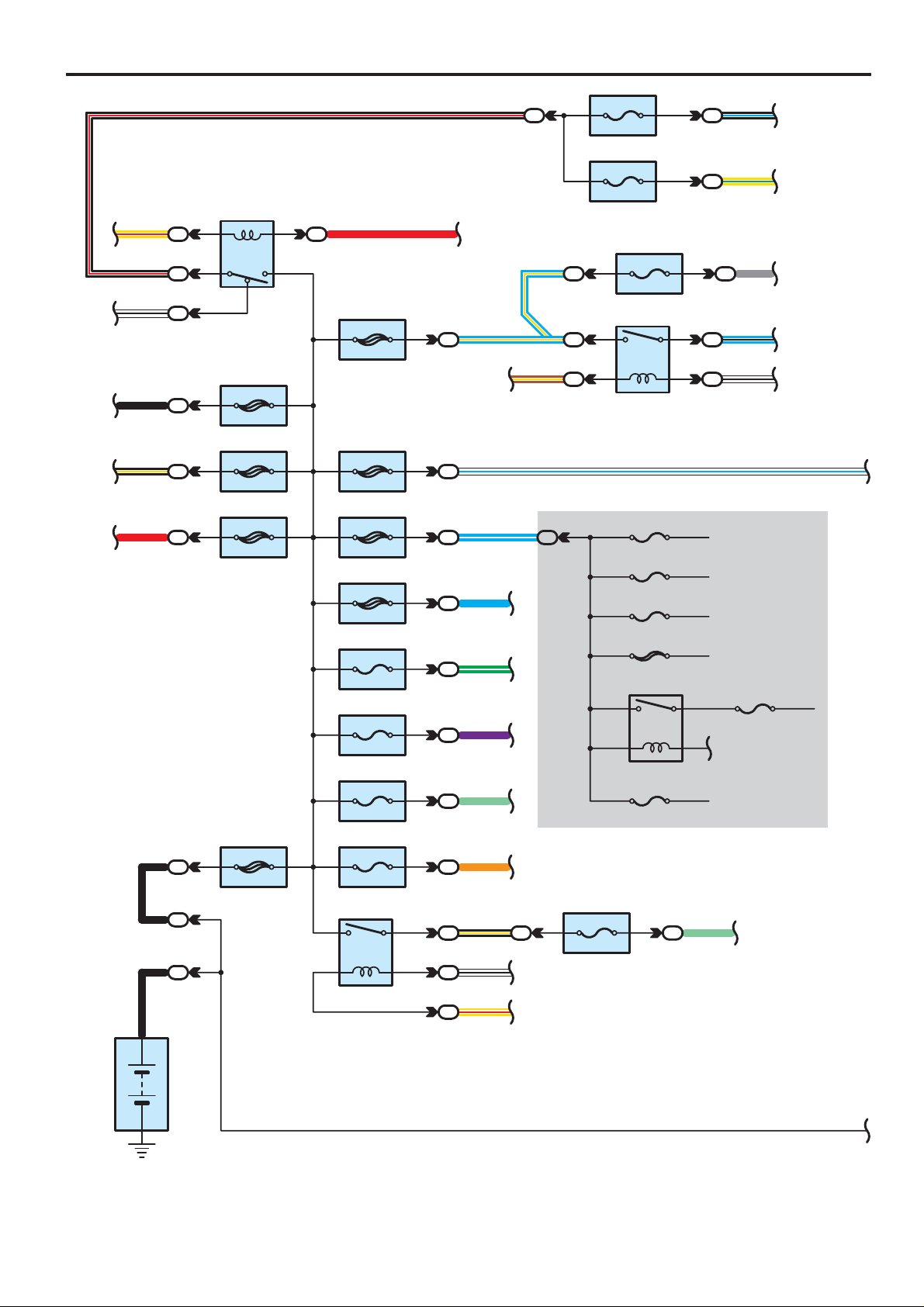
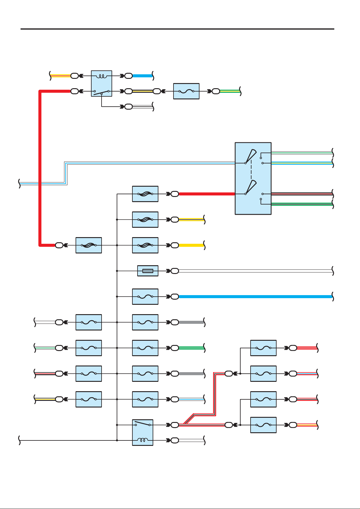
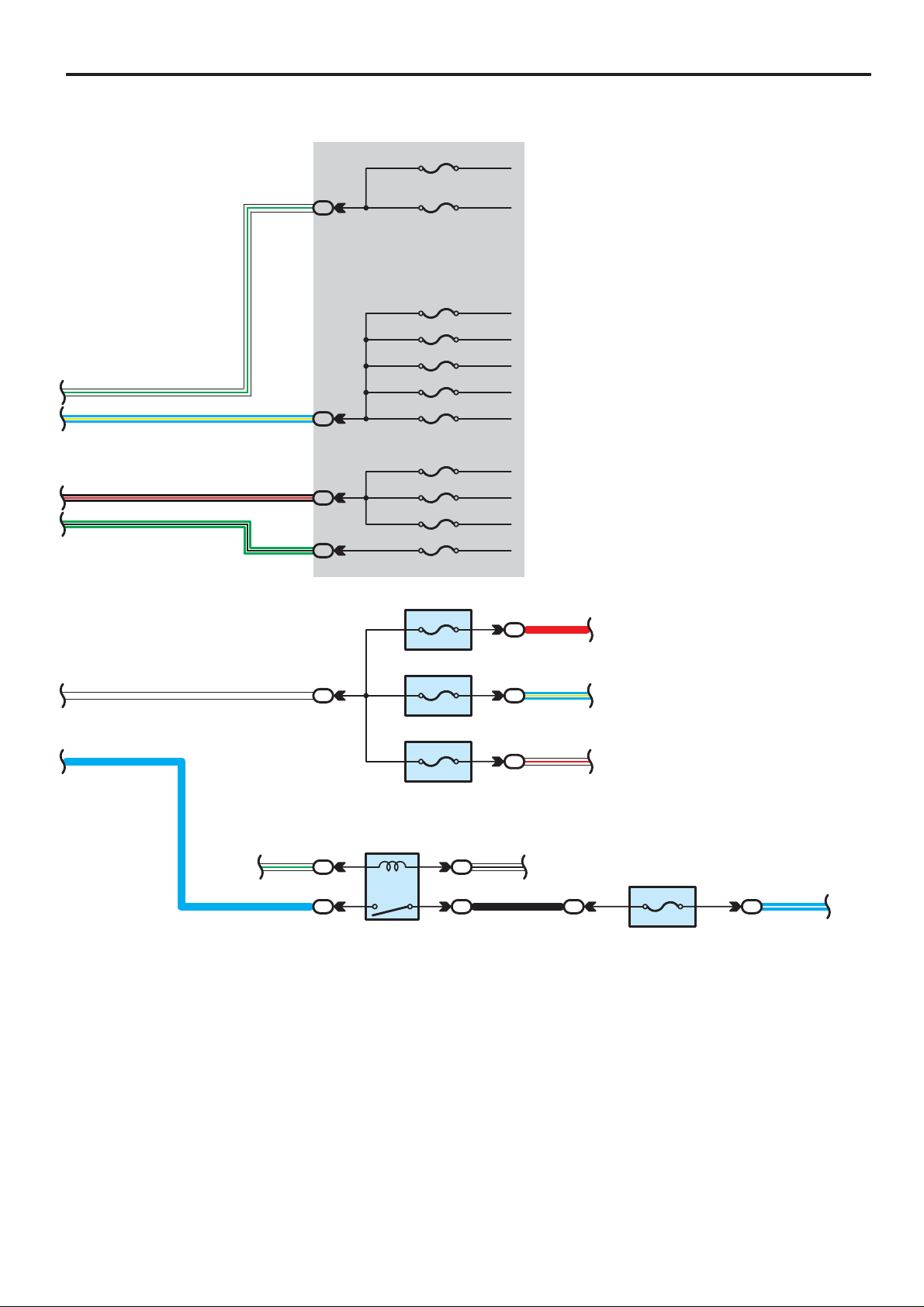
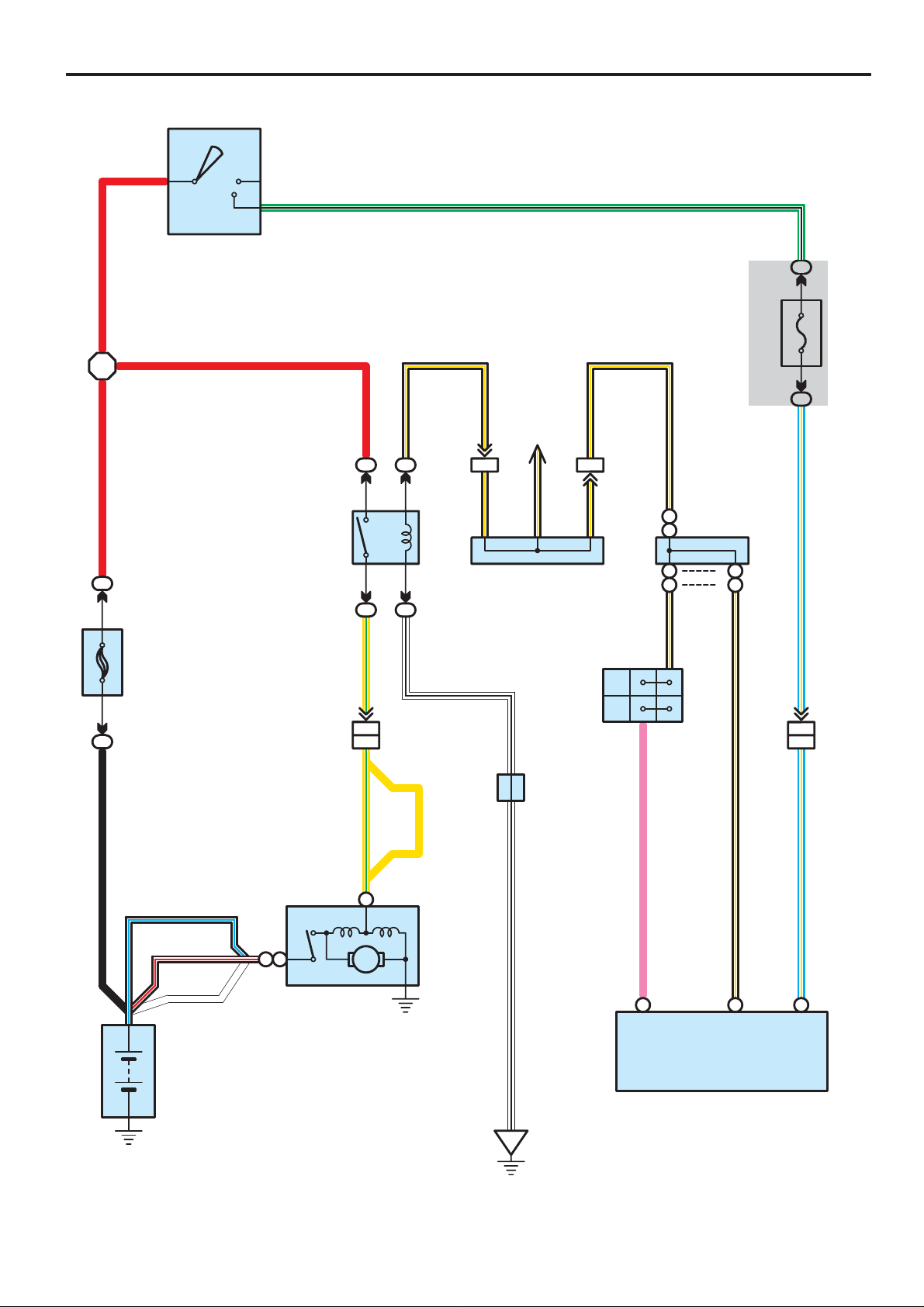
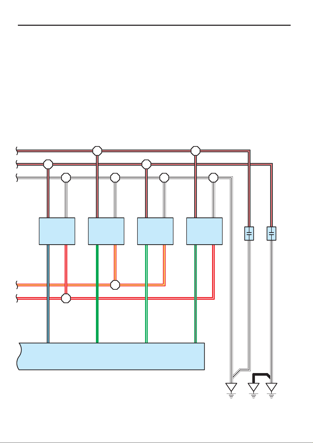
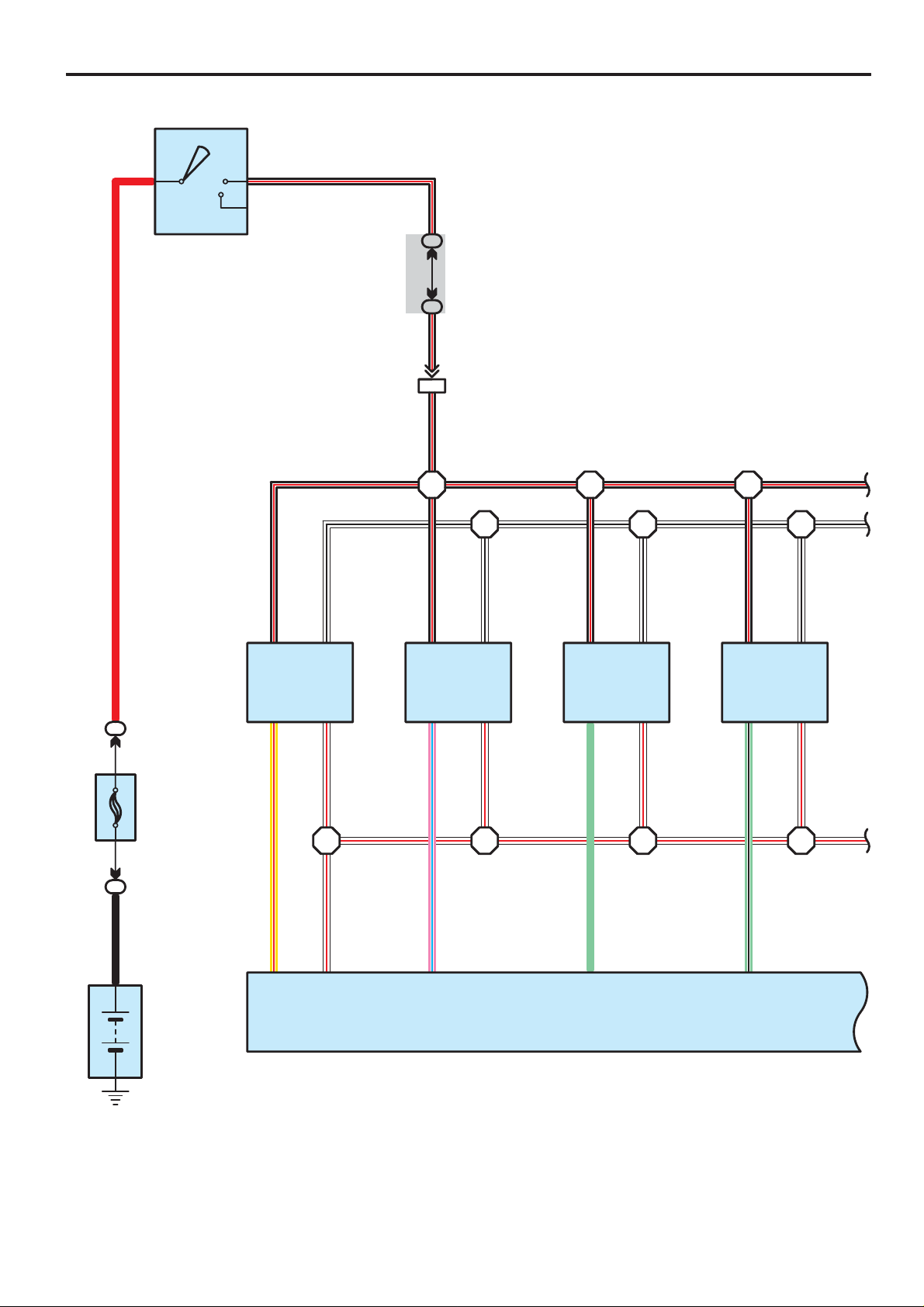
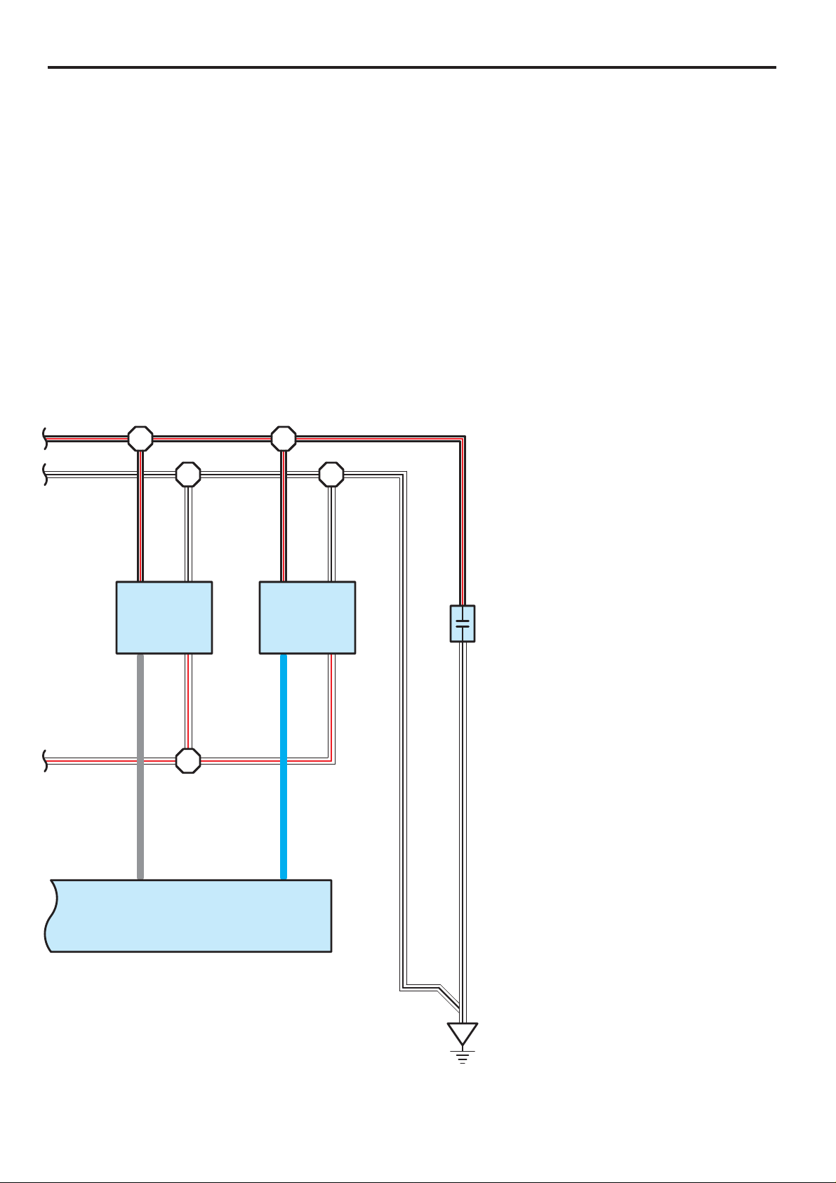
Power Source
10A MIR HEATER
B–R B–L
2
12
30A DEFOG
12
2
Y–G
2
Y–R
B–R
W–B
B
B–Y
R
2
2
2
2
2
2
DEFOG Relay
2
3
30A TOWING BRK
2
30A BATT CHG
2
50A A/PUMP
2
1
5
4
2
1
1
1
1
1
1
1
12
15A AC115V INV
12
R
2
50A AIR SUS
50A AM1
2
50A J/B
2
40A TOWING
2
10A STOP
4
4
GR
L–B
W–B
W–L
10A TAIL
12
22
L–Y
L–W
L
G–W
V
L–Y
BR–Y
1
1C
2
2
2
2
2
2
4
4
10A AIRSUS NO. 2
5
1
AIR SUS Relay
10A SECU/HORN
30A P P/SEAT
30A D P/SEAT
1
30A POWER
5
1
3
2
2
3
2
54
12
140A ALT
1
2
2
2
BB
Battery
2
12
5
1
15A FR FOG
7. 5A OBD
IG Relay
TAIL Relay
LG
2
O
2
25A SEAT HEATER
3
2
B–Y
2
W–B
2
Y–R
2
12
2
15A PWR OUTLET
2
LG
4RUNNER (EM00T0U)
Page 18
2
2
HEATER Relay
1
5
4
2
3
Y–R L
R
2
B–Y
2
W–B
2
7. 5A HEATER NO. 2
12
2
W–L
G–Y
2
I18
Ignition SW
3
ACC
2
AM1
IG1
4
W–G
L–Y
W–L
R
W
W–G
60A HEATER
2
2
7. 5A ALT–S
21
2
10A HORN
21
2
1
30A AM2
1
40A ABS MTR
1
30A ABS SOL
1
Short Pin
12
20A EFI
12
10A ETCS
12
20A DR/LCK
12
2
2
2
2
Y–B
2
Y
2
W
2
L
2
GR
2
G–W
2
R
7
AM2
10A HEAD(HI RH
12
IG2
ST2
6
8
)
2
B–R
G–B
W
L
R–W
B–R
B–Y
15A A/F HEATER
21
2
15A TRN–HAZ
21
2
30A TOWING
12
20A RADIO NO. 2
12
HEAD Relay
1
35
2
GR
2
W–L
2
2
W
2
R–B
R–B
4RUNNER (EM00T0U)
10A HEAD(HI LH
2
2
12
10A HEAD(LO RH
12
10A HEAD(LO LH
12
)
R–L
2
)
R–B
2
)
R–Y
2
55
Page 19
Power Source
7. 5A ACC
W–G
L–Y
B–R
G–B
W–G
1D
1C
1D
1D
5
2
6
3
10A CIG
15A IG1
10A ECU–IG
15A RR WSH
20A 4WD
30A FR WIP–WSH
10A IGN
7. 5A GAUGE
10A SRS
7. 5A STA NO. 2
10A DOME
21
R
2
20A RADIO NO. 1
W
L
W–G
L
2
2
2
12
10A ECU–B
21
EFI Relay
1
5
2
2
3
2
W–B
L–Y
2
W–R
2
10A EFI NO. 2
2
21
L–WB
2
56
4RUNNER (EM00T0U)
Page 20
: Parts Location
:
:
24
Engine Room Main Wire and Driver Side J/B (Lower Finish Panel)
Code See Page Code See Page Code See Page
I18 37
Relay Blocks
Code See Page Relay Blocks (Relay Block Location)
2 22 Engine Room R/B (Engine Compartment Left)
4 23 Engine Room R/B No.4 (Engine Compartment Left)
Junction Block and Wire Harness Connector
Code See Page Junction Block and Wire Harness (Connector Location)
1C
1D
4RUNNER (EM00T0U)
57
Page 21
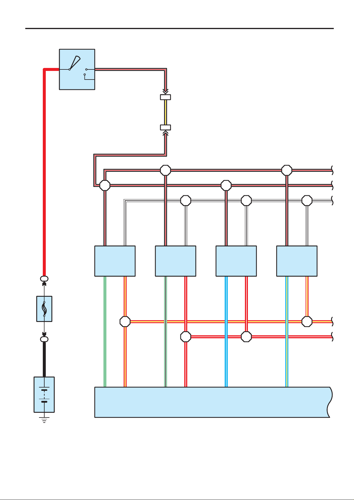
Starting
78AM2 IG2
ST2
G–B
∗ 1 : 2UZ–FE
∗ 2 : 1GR–FE
∗ 3 : 1GR– FE Cold Area Spec.
∗ 4 : 1GR– FE Except Cold Area Spec.
7. 5A
STA
NO. 2
)
)
G–BL–Y
1D3
1K2
L–Y
(∗1)
IM26
(∗2)
IM24
I18
Ignition SW
R
R
B–Y
RRB
2
2
30A
AM2
1
2
22
51
STA Relay
32
2
2
Y–G
W–B
(∗1)
EA16
(∗2)
EA24
B–Y
B–Y
GG
J35
Junction
Connector
B–Y
G
B
B–Y
Combination Meter
P 1
IM111IC42
B–Y
P
N
Park/Neutral
Position SW
)
A
(
, J28
)
B
(
J27
4
A(∗1
B
Junction
Connector
B–Y
)
A
(∗2)
B
AA
BB
B–Y
5
AA(∗1
BB(∗2
58
Battery
B–L
(∗3)
B–R
(∗1)
W
(∗4)
1
B1A
)
)
∗2
∗1
(
(
S 2(A), (B), S 3(C
Starter
)
∗1
(
Y–G
C1
M
)
)
Y
∗2
(
B
EB
W–B
J 3
P
B8
STAR/
NSW
E 5(B), E 6(C
Engine Control Module
)
B–Y B–Y
C11 C12
STA STSW
Junction
Connector
4RUNNER (EM00T0U)
Page 22
: Parts Location
S2
S3
C
J3
P1
:
:
:
Engine No.2 Wire and Engine Room Main Wire (Under the Engine Room R/B)
47
Engine Wire and Instrument Panel Wire (Right Side of Blower Unit)
:
EB
Front Left Fender
Code See Page Code See Page Code See Page
E5 B 37 J27 B 38
E6 C 37 J28 A 38
I18 37 J35 38
33 (2UZ–FE)
35 (1GR–FE)
33 (2UZ–FE)
35 (1GR–FE)
A 35 (1GR–FE)
B 33 (2UZ–FE)
33 (2UZ–FE)
35 (1GR–FE)
Relay Blocks
Code See Page Relay Blocks (Relay Block Location)
2 22 Engine Room R/B (Engine Compartment Left)
Junction Block and Wire Harness Connector
Code See Page Junction Block and Wire Harness (Connector Location)
1D 24 Engine Room Main Wire and Driver Side J/B (Lower Finish Panel)
1K 25 Instrument Panel Wire and Driver Side J/B (Lower Finish Panel)
Connector Joining Wire Harness and Wire Harness
Code See Page Joining Wire Harness and Wire Harness (Connector Location)
EA1 44 (2UZ–FE)
EA2 45 (1GR–FE)
IC4 46 Instrument Panel Wire and Engine Room Main Wire (Left Kick Panel)
IM1
IM2
Ground Points
Code See Page Ground Points Location
44 (2UZ–FE)
45 (1GR–FE)
4RUNNER (EM00T0U)
59
Page 23
Ignition for 2UZ–FE
76AM2 IG2
I18
Ignition SW
R RB
ST2
B–R
EA17
B–Y
EB11
B–R
B–R
B–R
W–B
B–R
1
W–B
B–R
W–B
B–R
W–B
41414
B–RB–R
B–R
B–RB–R
B–R
W–BW–B
W–B
41
I 1
Ignition Coil and
2
2
30A
AM2
1
2
Battery
Igniter No. 1
LG
LG
8
IGT1
R–Y
R–Y
24 15
IGF1 IGT3
I 2
Ignition Coil and
Igniter No. 2
LG–B
LG–B
IGT2
R–W
R–W
25
IGF2
E 4
Engine Control Module
R–YR–Y
R–W
I 3
Ignition Coil and
Igniter No. 3
L–W
L–W
11
232323
R–W
R–Y
R–W
I 4
Ignition Coil and
Igniter No. 4
L–Y
L–Y
10
IGT4
23
R–Y
R–Y
R–W
60
4RUNNER (EM00T0U)
Page 24
B–R
B–R B–RB–R
B–R
R–Y
R–W
W–B
41
23
R–Y
B–R
W–B
I 8
Ignition Coil and
B–R
Igniter No. 8
G–B
W–B
41
23
R–W
W–B
N 2
B–R
)
2
Ignition No. 2
Noise Filter
(
1
N 1
)
2
Ignition No. 1
Noise Filter
(
1
B–R
W–B
41
23
R–Y
W–B
I 7
R–Y
R–W
Ignition Coil and
B–R
Igniter No. 7
G–W
W–BW–B
B–R
I 5
Ignition Coil and
Igniter No. 5
B–L
W–B
41
23
R–W
I 6
R–Y
R–W
Ignition Coil and
B–R
Igniter No. 6
G
13
IGT5
B–L
G
12 14
IGT6
E 4
Engine Control Module
G–W
IGT7
G–B
9
IGT8
W–B
ED
W–B
ER
W–B B–R
B
EC
61
4RUNNER (EM00T0U)
Page 25
Ignition for 2UZ–FE
:
:
:
: Parts Location
Code See Page Code See Page Code See Page
E4 37 I4 33 (2UZ–FE) I8 33 (2UZ–FE)
I1 33 (2UZ–FE) I5 33 (2UZ–FE) I18 37
I2 33 (2UZ–FE) I6 33 (2UZ–FE) N1 33 (2UZ–FE)
I3 33 (2UZ–FE) I7 33 (2UZ–FE) N2 33 (2UZ–FE)
Relay Blocks
Code See Page Relay Blocks (Relay Block Location)
2 22 Engine Room R/B (Engine Compartment Left)
Connector Joining Wire Harness and Wire Harness
Code See Page Joining Wire Harness and Wire Harness (Connector Location)
EA1 44 (2UZ–FE) Engine No.2 Wire and Engine Room Main Wire (Under the Engine Room R/B)
EB1 44 (2UZ–FE) Engine No.2 Wire and Engine Wire (Near the Starter)
Ground Points
Code See Page Ground Points Location
EC 44 (2UZ–FE) Right Bank Cylinder Head
ED 44 (2UZ–FE) Left Bank Cylinder Head
ER 44 (2UZ–FE) Rear Side of Front Right Fender
62
4RUNNER (EM00T0U)
Page 26

Memo
4RUNNER (EM00T0U)
63
Page 27
Ignition for 1GR–FE
76AM2 IG2
I18
Ignition SW
R RB
ST2
B–R
1D6
41H
B–R
13 IM1
B–R
B–RB–R
W–B
B–R
1
W–B
B–R
W–B
B–R
W–B
41414
B–R
1
B–R
W–BW–B
W–B
4
I 1
Ignition Coil and
2
2
30A
AM2
1
2
Battery
Igniter No. 1
Y–R
Y–R
8 11
IGT1
W–R
W–R
IGF1 IGT3
I 2
Ignition Coil and
Igniter No. 2
P–L
P–L
924
IGT2
W–R
E 4
Engine Control Module
I 3
Ignition Coil and
Igniter No. 3
LG
LG
10
232323
W–R
I 4
Ignition Coil and
Igniter No. 4
LG–B
LG–B
IGT4
23
W–R
W–RW–RW–RW–R
64
4RUNNER (EM00T0U)
Page 28
B–R
B–R
W–BW–B
B–R
I 5
Ignition Coil and
Igniter No. 5
GR
W–R W–R
GR
12 13
IGT5
W–B
41
23
W–R
N 1
B–R
)
2
Ignition No. 1
Noise Filter
(
1
W–B
B–R
I 6
Ignition Coil and
Igniter No. 6
L
L
IGT6
W–B
41
23
W–R
W–B
W–B
E 4
Engine Control Module
EF
65
4RUNNER (EM00T0U)
Page 29
Ignition for 1GR–FE
:
:
:
:
: Parts Location
Code See Page Code See Page Code See Page
E4 37 I3 35 (1GR–FE) I6 35 (1GR–FE)
I1 35 (1GR–FE) I4 35 (1GR–FE) I18 37
I2 35 (1GR–FE) I5 35 (1GR–FE) N1 35 (1GR–FE)
Relay Blocks
Code See Page Relay Blocks (Relay Block Location)
2 22 Engine Room R/B (Engine Compartment Left)
Junction Block and Wire Harness Connector
Code See Page Junction Block and Wire Harness (Connector Location)
1D 24 Engine Room Main Wire and Driver Side J/B (Lower Finish Panel)
1H 25 Instrument Panel Wire and Driver Side J/B (Lower Finish Panel)
Connector Joining Wire Harness and Wire Harness
Code See Page Joining Wire Harness and Wire Harness (Connector Location)
IM1 47 Engine Wire and Instrument Panel Wire (Right Side of Blower Unit)
Ground Points
Code See Page Ground Points Location
EF 45 (1GR–FE) Rear Side of Left Bank Cylinder Block
66
4RUNNER (EM00T0U)
Page 30

Memo
4RUNNER (EM00T0U)
67
Page 31

Charging
W
2
W–L
2
2
50A AM1
1
2
140A ALT
1
2
B
2
ACC
W–L
R
R
22
2
AM1
7
ST2
I18
Ignition SW
∗ 1 : 2UZ–FE
∗ 2 : 1GR–FE
W
22
IG1
IG2
L–Y
4
B–R
6AM2
5 EA1 EA11
1 EA2
B 4
Body ECU
14
)
B
(
, J19
)
A
(
J18
Junction
Connector
L
BE
AAAA
IC46
GR GR GR
EA23
(∗1)
(∗2)
B–R
GR
)
C
(
, C10
)
A
(
C 8
Combination Meter
)
B
(
, J 9
)
A
(
J 8
Charge
Junction
Connector
1D6
1G4
R–L
GR
1C2
1E20
Y–RY–RY–R L–Y
E
Connector
E
D
Connector
D
EA12
EA22
(∗1)
(∗2)
15A
IG1
7. 5A
GAUGE
C15
Junction
A16
J 1 J 1
Junction
BG
AG
68
Y–R
30A AM2
1
7. 5A ALT–S
1
2
B
Battery
W
S
G 1(A), G 2(B
Generator
GR
Y–R
B4B2B1A1
LIG B
IC Regulator
)
W
4RUNNER (EM00T0U)
Page 32

: Parts Location
G2
B
G1
A
J1
:
:
24
Engine Room Main Wire and Driver Side J/B (Lower Finish Panel)
24
Engine Room Main Wire and Driver Side J/B (Lower Finish Panel)
:
Engine No.2 Wire and Engine Room Main Wire (Under the Engine Room R/B)
Code See Page Code See Page Code See Page
B4 36
C8 A 37
C10 C 37 I18 37 J18 A 38
32 (2UZ–FE)
34 (1GR–FE)
32 (2UZ–FE) J8 A 38
34 (1GR–FE) J9 B 38
33 (2UZ–FE) J19 B 38
35 (1GR–FE)
Relay Blocks
Code See Page Relay Blocks (Relay Block Location)
2 22 Engine Room R/B (Engine Compartment Left)
Junction Block and Wire Harness Connector
Code See Page Junction Block and Wire Harness (Connector Location)
1C
1D
1E
1G 25 Instrument Panel Wire and Driver Side J/B (Lower Finish Panel)
Connector Joining Wire Harness and Wire Harness
Code See Page Joining Wire Harness and Wire Harness (Connector Location)
EA1 44 (2UZ–FE)
EA2 45 (1GR–FE)
IC4 46 Instrument Panel Wire and Engine Room Main Wire (Left Kick Panel)
4RUNNER (EM00T0U)
69
Page 33

Engine Control for 2UZ–FE
)
ACC
BAT
B
(
)(
BAT
)(
7. 5A
ACC
1K8
ACC
AM1
76AM2
I18
Ignition SW
RR
2
2
IG1
IG2
ST2
P
F3E
3EF
P
38 IC4
P
22
32
ACC CUT Relay
41
22
GR
B–R
L
W–G
15A
A/F HEATER
2
2
L
W–G
B–R
22 22
2
15
A/F HEATER Relay
23
2
2
2
W
W–B
15
EFI Relay
23
22 22
20A
EFI
2
2
L
L
B
B
B
B
BL–W
2
1
B
51
C/OPN Relay
32
B–W
B
B–R
W–G
L
B–O
B–W
GR–B
GR–B
70
IC411 IC433
30A AM2
1
2
B
Battery
IC49
W
IM14
AB
J 2(A), J 3(B
Junction
Connector
)
W–B
BA
BB
W–B
EB
10A EFI NO. 2
2
2
A
J 4
A
Junction
Connector
A
L–W
L–W
IC317IB21
B
GR–B
GR–B
B
L–W
L–W
W
W–G
4RUNNER (EM00T0U)
Page 34

BB
B–R
W–G
L
B–O
B–W
FUEL PUMP Relay
B–W
22
23
4
15
22 2
F 8
B–R
B–R
2
Fuel Pump
Resistor
1
B–Y
G–R
IC45
G–R
IM219
G–R
J 4
)
B
(
, J41
)
A
(
J40
B–R
C
Junction
Connector
C
B–O B–O
2IB1
B–R
4
M
5
W–B
BABA
AA
Junction
Connector
W–B
B–O
F14
23 1E
Fuel Pump
10A
IGN
)
A
(
J 8
W–B
6
11 1J
Junction
Connector
B–R
1D
B–O B–O
B–R B–R
L
IC412
L
IGSW
E9
B–O
BB
)
B
(
AB
, J32
)
A
(
J31
BA
Junction
Connector
B–O
AB
8
EA1
P 1
Park/Neutral
Position SW
W–G
IC435
W–G
8
E3E
MRELBATT
E 4(A), E 5(B), E 6(C), E 7(D), E 8(E
Engine Control Module
FCFPR
10 E30 C
G–R
GR–B
)
B
(
, J32
)
A
(
CA
J31
Junction Connector
+B
BB
P
N
E1
EB1
4
P
B8
STAR/
NSW
+B2
2E
ABAB
4
B
B–R
5
STA Relay
B–Y
A
A
B–Y B–Y
STA
A
J28
Junction
Connector
C11
)
17 E
16
ACCR
W–G
IC3
W–G
AIV2
A26
L
)
2
11
Air Switching Valve Bank 1
(
VSV
V12
L–W
V13
AIV1
)
2
Air Switching Valve Bank 2
(
VSV
A27
P
L–W
GR–B
B
L–W
L–W
W
W–G
L–W
L–W
L–W
W
L–W
BLBO
71
4RUNNER (EM00T0U)
Page 35

Engine Control for 2UZ–FE
BB
6E
R–L
Combination Meter
VPMPMPMP
5E
B–RB–RB–RB–RB–R
I12
B–R
I13
Injector No. 4
2
Y
5C
#40
Injector No. 5
)
B–R
11
I 9
Injector No. 1
2
R–LR–L
A
A
Junction
J26
A
#10
PPMP
22 E
B–R
1
I10
Injector No. 2
2
L
Connector
3C2
#20
L 4
Canister Pump Module
B–R
1
I11
Injector No. 3
2
W
4C
#30
E 4(A), E 5(B), E 6(C), E 7(D), E 8(E
Engine Control Module
B–R
1
2
G
C
6C
#50
B–R B–R
1
I14
Injector No. 6
2
RB–R
C
7
#60
1
Injector No. 7
I15
2
WB–R
A
3
#70
32
AIP
I16
A
1
Injector No. 8
2
BR B–R
A
2
#80
L–W
L–W
W
L–W
BR
43 IE1
BR
22 IM2
Canister
Pressure Sensor
42 IE1
7IM2
1 EB2
W–L W–L
2
AIP
4296183
L–RL–R
1
BR
VCE2
3
L–R
3 EB24 EB2
A45
L–R
BR
L–W
L–W
L–R
W
BR
Air Pressure Sensor
O
R
R–G
Vent Valve
R
17 IE1
R
R–G
11 IE1
R–G
L–W
O
28 IE1
O
Leak
Detection Pump
M
9IE1
16 IM2
W–B
W–B
W–B
72
ED
4RUNNER (EM00T0U)
Page 36

B B
∗ 1 : Shielded
(ST)
7. 5A
STA
NO. 2
A24
Accel Position Sensor
21K
2
1
Camshaft Timing Oil
Control Valve LH
C 2
P
LG
2
VPA1 VPA2 VCP1 VCP2 EP1 EP2
1
Camshaft Timing Oil
Control Valve RH
C 3
6IM2
R–W
Y–R
L–Y L–Y
634152
W–R
W–R
R–B
R–B
B–Y
B–Y
W–L
W–L
LG–B
IC429 IC389IC326 IC431 IC434 IC4
LG–B
V–W
V–W
17 C
OC1+ OC1– OC2+
L–R
BR
L–W
16 C
L–R
L–R
L–R
15 C
RL–R
T 2
Throttle Control Motor
Throttle Position Sensor
14 C
VTA1VC
20 A23 A
Y
12 C
VTA2
R–B
STSW
)
∗1
(
M+
5A
R
BR
M–
4A
G
12465
M–M+VTA2VTA1VC
E2
3
W
BR
OC2–
E 4(A), E 5(B), E 6(C), E 7(D), E 8(E
Engine Control Module
19 A
VPA
)
GE01
17 A
BR BR
19 EE18
VPA2
21 A 30 A
Engine Coolant
Temp. Sensor
E 2
L–W
L–W
VCPA
THW
R–L
2
1
BR
C
E27
)
B
(
M 1
E26
VCP2
VG
W–R
B3B2B4
VG E2G THA
E2 +B
Mass Air
Flow Meter
B5B1
BR
D
E20
EPAEEPA2
E2G
29 A
B–W
J28
Junction
Connector
21
THA
22 A
Y–B
L–W
BR
L–R
C
L–W
L–R
W W
BR
12
IM1
L–W
D
C
4RUNNER (EM00T0U)
73
Page 37

Engine Control for 2UZ–FE
BB
∗ 1 : Shielded
R–Y R–Y
R–W
R–Y
2
Ignition Coil and
Igniter No. 1
I 1
3 33333
R–Y
24
A
IGF1
PRG
34 A
Y–R
LG
8A
IGT1
ACIS
33
I 2
E2
28 A
A
R
BR
Ignition Coil and
Igniter No. 2
2
15 A
IGT2
)
∗1
(
R–W
LG–B
A2A+ HA2A
23 B
P
R–W
222
Ignition Coil and
Igniter No. 3
I 3
L–W
11 A
IGT3
E 4(A), E 5(B), E 6(C), E 7(D), E 8(E
Engine Control Module
A2A–
31 B
L
B–W
R–Y
Ignition Coil and
Ignition Coil and
Igniter No. 4
I 4
L–Y
10 A
IGT4
Igniter No. 5
I 5
13 A
)
A1A+
22 B
)
∗1
(
Y
A1A–
30 B
BR
R–W
B–L
IGT5
R–W
HA1A
B2B1
R–L
R–W
R–Y
2
Ignition Coil and
Igniter No. 6
I 6
G
12 A
IGT6
OX2B
33 B
)
∗1
(
5B
W
Ignition Coil and
I 7
HT2B
Igniter No. 7
R–Y
2
3
G–W
14 A
IGT7
BR
L–R
W
)
(
B
V 2
)
Purge
(
VSV
B1B2
B2B1
L–W
C
)
B
(
V 1
)
ACIS
(
VSV
DC
D
L–W
BR
J28
Junction
Connector
L–W
434313
)
Bank 1 Sensor 1
Air Fuel Ratio Sensor
(
A12
L–W
E
E
E
E
A13
)
Bank 2 Sensor 1
Air Fuel Ratio Sensor
(
W–B
1212
W
J28
Junction
Connector
E
EE
AF+ AF– HTOXAF–AF+
W
BR BR
J26
C
Junction
Connector
W
CC
)
E1+BHT+BHT+B
42
BR P
H 8
Bank 2 Sensor 2
Heated Oxygen Sensor
(
BR
(∗1)
W–B
L–R
W–B
W–B
W–B
L–W
74
4RUNNER (EM00T0U)
Page 38

B
(
BAT
)
BAT
)(
B
R–W
10A
ETCS
A32
Airbag Sensor
Assembly
R–W
2
Ignition Coil and
Igniter No. 8
I 8
3
G–B
9A
IGT8
OX1B
A18
R–W
25 A
IGF2
HT1B
A1
GSW2
23
32 D
F/PS
L
IL12
L
19
G2+3G2–
C
T 8
Transponder Key
Computer
EFIO
6
W–R
16 D
IMI
E 4(A), E 5(B), E 6(C), E 7(D), E 8(E
Engine Control Module
C
29
EFII
7
L–R
D15
IMO
C25
2
2
GRGR
J 4
S12
Junction
IC413
7E
+BM
)
VV1–VV1+
24
C
VV2+
C18
VV2–
C28
2
2
G–W
2
Stop Light SW
1
G–Y
B
Connector
B
10A
STOP
G–Y
G–Y
3CE
AH
)
B
3CE
G–Y
IC315
NE–
(
, J32
)
A
(
BE
J31
Junction
Connector
G–Y
15 E
STP
NE+
C21
C20
BR
(∗1)
W–B
L–R
W–B
W–B
W–B
)
∗1
(
B
31
OX HT
E1 +B
42
BR
G–Y
H 6
L–W
)
Bank 1 Sensor 2
Heated Oxygen Sensor
(
)
∗1
(
)
B
(
V 4
R
G
VVT Sensor RH
C 1
Camshaft Position
Sensor
)
∗1
(
)
(
B
V 3
VVT Sensor LH
W
12
L–R B
L
Y
B1B1B2
B2B2B1
W–B
)
∗1
(
)
B
(
C 4
Crankshaft
Y
Position Sensor
L
W–B
L–W
ED
75
4RUNNER (EM00T0U)
Page 39

Engine Control for 2UZ–FE
B B
BAT
50A
J/B
2
L–W
1C1
15
TAIL Relay
23
)
10A
TAIL
51L
G
B
J16
Junction
Connector
B
G
3DD
3DD
E 4(A), E 5(B), E 6(C), E 7(D), E 8(E
Engine Control Module
DA
G
IB
G
13 D
ELS1
∗ 1 : Shielded
D
B
Y–G
D12
ELS2
)
B
(
, J32
)
A
(
J31
)
Y–G
Junction
Connector
)
B
(
, J23
)
A
(
J22
EB
Junction
Connector
DA
30A
DEFOG
2
1
2
2
Y–GY–G
18IAIC4
(
)(
BAT
140A
ALT
22
51
DEFOG
Relay
32
2
B–R
W–B
KNK2 EKNK
21 B
)
∗1
(
2 EB1
)
∗1
(
EKN2
B20
WW
B
EB13EB1 7 EB1EB168
B
B2
)
)
B
(
Bank 2
Knock Sensor
(
K 2
B1
BR
BR
KNK1
B29
)
G
∗1
(
)
G
∗1
(
1
2
K 1
28 B
)
Knock Sensor
(
R
R
Bank 1
THWO
D14
BH
)
B
(
, J32
)
A
(
AE
J31
Junction
Connector
L–B L–B
3DC
3DC
L–B
A7A18 B7
A16(A), A17(B
A/C C o nt ro l A ss embly
ACT
D25
BR–W
IK12IK11
BR–W
ACTTWI
)
AC1
D24
GR–G
GR–G
AC1
4WD
C8
W–B W–B
)(
4WD
(
)
4WD
E1
C14B6A7A
W–B
W–B
W–B
W–B
W–B
W–B
W–B
W–B
W–B
W–B
E05E04E03E02E01
6B7B
W–B
W–B
76
4RUNNER (EM00T0U)
EE
EE
Page 40

B
F 9
4WD Control ECU
(
BAT
)
50A
A/PUMP
)
B
(
, J30
)
A
(
J29
24
Junction
Connector
13 C
ME01
3B
BRBR
L4
W–L
BH
AF
W–L
IM25
W–L
L4
2
2
)
4WD
(
P–L
EA
)
B
)
4WD
(
)
4WD
(
LG
33 D34 D
E 4(A), E 5(B), E 6(C), E 7(D), E 8(E
Engine Control Module
EC
9C
W–BW–B
(
, J30
)
A
(
AB
Junction
Connector
J29
L
CANHCANL
P–L
TC
E23
25 E
G
AIRP
Y
AIRV
V
13 E
AIDI
)
EOM
D35
W–B
TACHSPD
8D D30
D1
V–R
B–W
W
R–B
V
Y
IC3 IC31410
V
2B
DI
)
B
(
, A44
)
A
(
2A
A43
Air Injection Control Driver
G
Y
3B
SIV
G
IC34
G
4B
SIP
6B
L
B
5B
+B
1
EVVVP
B1
BRBR
R
A
BATT
LG
L
P–L
ED
IM21
AB
)
B
(
, J34
)
A
(
Junction
Connector
J33
AA
AA
W–B
A
J37
Junction
Connector
IK
3 EA1
Air Pump
A46
G
2
M
1
W–B
W–B
EQ
4 EA1
Air Switching Valve
A47
L
1
2
W–B
IN14E4
BR
R–B
B–W
V–R
4RUNNER (EM00T0U)
77
Page 41

Engine Control for 2UZ–FE
(
)
BAT
7. 5A
OBD
2
2
LG
L
P–L
3C
3CCC
O
IC432
Y 1
Yaw Rate Sensor
D 1
J18
Junction
Data Link
Connector 3
H
Connector
H
P–L P–L
13 16
TC BAT
BR
AAAA
CANH CANL
3
Connector
W
C1
B
3
S11
Steering Sensor
)
B
(
, J36
)
A
(
J35
V
14
CANL
Junction
Connector
OBR
SG CG
54
BE
BR
IM29
P
6
CANH
W–B
AE
AE
)
A
(
Junction
J22
2
R
B2B1
C2
Y
11
P
D1
A1
B
IC211
B
11
CANH CANLCANLCANH
V
D2
A2
W
IC222
W
25
SP1
12
L
E1
J47(A), J48(B), J49(C),
J50(D), J51(E), J52(F
Junction
Connector
S28
Skid Control ECU
with Actuator
LG
E2
ST–Plug
)
F1
W–B
78
BR
R–B
B–W
V–R
BR
W–B
A
J 5
Junction
Connector
IGED
4RUNNER (EM00T0U)
GR–R
GR–R
R–B
B–W
V–R
IH
Page 42

(
BAT
)(IG)
)
C
(
, C10
)
B
(
, C 9
)
A
(
C 8
7. 5A
GAUGE
1G4
R–L
C15 C16
Malfunction
Indicator Lamp
Combination Meter
4B
A76BB5
)
B
(
, J 9
)
A
(
J 8
Junction
Connector
10A
DOME
R
J 7
Speedometer
Junction
Connector
D
D
R
AH
BF
R
2
2
R
IC410
Tachometer
C13
GR–R
R–B
B–W
V–R
)
B
(
, J30
)
A
(
Junction Connector
J29
BR
IM17
BR
R–B
GR–R
7IC2
GR–R
B–W
)
BH
B
(
, J 9
)
A
(
J 8
Junction
AF
B–W
AG
)
B
(
, J32
)
A
(
BF
Junction Connector
J31
B–W
Connector
V–R
1G1
1K11
3DB
3DB
V–R V–R
AG
BG
V–R
4RUNNER (EM00T0U)
ED
79
Page 43

Engine Control for 2UZ–FE
System Outline
The engine control system utilizes a microcomputer and maintains overall control of the engine, transmission etc. An outline
of the engine control is given here.
1. Input Signals
(1) Engine coolant temp. signal circuit
The engine coolant temp. sensor detects the engine coolant temp. and has a built–in thermistor with a resistance which
varies according to the engine coolant temp. The engine coolant temp. is input into TERMINAL THW of the engine
control module as a control signal.
(2) Intake air temp. signal circuit
The intake air temp. sensor is installed in the mass air flow meter and detects the intake air temp., which is input as a
control signal to TERMINAL THA of the engine control module.
(3) Oxygen sensor signal circuit
The oxygen density in the exhaust emission is detected and is input as a control signal from the heated oxygen sensors
to TERMINALS OX1B and OX2B of the engine control module.
(4) RPM signal circuit
The camshaft position is detected by the camshaft position sensor and is input into TERMINAL G2+ of the engine
control module as a control signal. Also, the engine RPM is detected by the crankshaft position sensor and the signal is
input into TERMINAL NE+ of the engine control module.
(5) Throttle position sensor signal circuit
The throttle position sensor detects the throttle valve opening angle as a control signal, which is input into TERMINALS
VT A1 and VTA2 of the engine control module.
(6) Vehicle speed circuit
The vehicle speed sensor detects the vehicle speed, and the signal is input into TERMINAL SPD of the engine control
module via the combination meter, from TERMINAL SP1 of the skid control ECU with actuator.
(7) Battery signal circuit
Voltage is constantly applied to TERMINAL BATT of the engine control module. When the ignition SW is turned on, the
voltage for engine control module start up power supply is applied through the EFI relay, to TERMINALS +B and +B2 of
the engine control module. The current from the IGN fuse flows to TERMINAL IGSW of the engine control module, and
voltage is constantly applied to TERMINAL +BM.
(8) Intake air volume signal circuit
The intake air volume is detected by the mass air flow meter, and is input as a control signal to TERMINAL VG of the
engine control module.
(9) Stop light SW signal circuit
The stop light SW is used to detect whether the vehicle is braking or not, and the signal is input into TERMINAL STP of
the engine control module as a control signal.
(10)Starter signal circuit
To confirm whether the engine is cranking, the voltage applied to the starter motor when the engine is cranking is
detected, and is input into TERMINAL ST A of the engine control module as a control signal.
(11)Engine knock signal circuit
Engine knocking is detected by the knock sensors, and is input into TERMINALS KNK1 and KNK2 of the engine control
module as a control signal.
(12)A/C SW signal system
The operating voltage of the A/C magnetic clutch is detected and input in the form of a control signal to TERMINAL AC1
of the engine control module.
(13)Air fuel ratio signal system
The air fuel ratio is detected by air fuel ratio sensor and input as a control signal into TERMINALS A1A+ and A2A+ of
engine control module.
80
4RUNNER (EM00T0U)
Page 44

2. Control System
∗ SFI system
The SFI system monitors the engine condition through the signals input from each sensors to the engine control module.
The control signal is sent to the engine control module TERMINALS #10, #20, #30, #40, #50, #60, #70 and #80 to operate
the injector (Fuel injection). The SFI system controls the fuel injection by the engine control module in response to the
driving conditions.
∗ ESA system
The ESA system monitors the engine condition through the signals input from each sensors to the engine control module.
The best ignition timing is decided according to this data and the data memorized in the engine control module. The
control signal is output to TERMINALS IGT1, IGT2, IGT3, IGT4, IGT5, IGT6, IGT7 and IGT8, and these signals control the
igniter to provide the best ignition timing.
∗ Heated oxygen sensor heater control system
The heated oxygen sensor heater control system turns the heater on when the intake air volume is low (Temp. of exhaust
emission is low), and warms up the heated oxygen sensors to improve their detection performance. The engine control
module evaluates the signals from each sensors, and outputs current to TERMINAL HT1B or HT2B to control the heater.
∗ Air fuel ratio sensor heater control system
The air fuel ratio sensor heater control system turns the heater on when the intake air volume is low (Temp. of exhaust
emission is low), and warms up the air fuel ratio sensor to improve detection performance of the sensor.
The engine control module evaluates the signals from each sensor, current is output to TERMINALS HA1A and HA2A,
controlling the heater .
∗ Fuel pump control system
The engine control module supplies current to TERMINAL FPR, and controls the operation speed of the fuel pump with
the FUEL PUMP relay .
∗ ACIS
The ACIS includes a valve in the bulkhead separating the surge tank into two parts. This valve is opened and closed in
accordance with the driving conditions to control the intake manifold length in two stages, for increased engine output in all
ranges from low to high speeds.
∗ ETCS–i
The ETCS–i controls the engine output at its optimal level in accordance with the opening of the accelerator pedal, under
all driving conditions.
∗ Engine start control system
The engine control module allows power to be supplied from the TERMINAL STAR/NSW to the STA relay via park/neutral
position SW until complete combustion is confirmed by engine RPM after the detection of ignition SW ST signal by the
TERMINAL STSW.
With this arrangement, engine can be started without holding the ignition key in the ST position. At the same time, the
TERMINAL ACCR is controlled so that the engine control module turns off ACC CUT relay, shutting off power to the
accessories.
∗ VVT–i
Controls the intake camshaft to an optimal valve timing in accordance with the engine condition.
∗ Air Injection System
It is the system to improve exhaust control performance by activating catalyst at early stage, which is realized when air is
pressed and sent into the exhaust pipe forcibly by the air injection pump at starting engine in cold condition.
3. Diagnosis System
When there is a malfunction in the engine control module signal system, the malfunctioning system is recorded in the
memory. The malfunctioning system can be found by reading the code displayed on the malfunction indicator lamp.
4. Fail–Safe System
When a malfunction has occurred in any system, there is a possibility of causing engine trouble due to continued control
based on that system. In that case, the fail–safe system either controls the system using the data (Standard values)
recorded in the engine control module memory , or else stops the engine.
4RUNNER (EM00T0U)
81
Page 45

Engine Control for 2UZ–FE
:
:
24
Engine Room Main Wire and Driver Side J/B (Lower Finish Panel)
24
Engine Room Main Wire and Driver Side J/B (Lower Finish Panel)
25
Instrument Panel Wire and Driver Side J/B (Lower Finish Panel)
28
Instrument Panel Wire and Center J/B (Instrument Panel Brace RH)
28
Instrument Panel Wire and Center J/B (Instrument Panel Brace RH)
: Parts Location
Code See Page Code See Page Code See Page
A12 32 (2UZ–FE) I3 33 (2UZ–FE) J33 A 38
A13 32 (2UZ–FE) I4 33 (2UZ–FE) J34 B 38
A16 A 36 I5 33 (2UZ–FE) J35 A 38
A17 B 36 I6 33 (2UZ–FE) J36 B 38
A24 36 I7 33 (2UZ–FE) J37 38
A32 36 I8 33 (2UZ–FE) J40 A 40
A43 A 32 (2UZ–FE) I9 33 (2UZ–FE) J41 B 40
A44 B 32 (2UZ–FE) I10 33 (2UZ–FE) J47 A 38
A45 32 (2UZ–FE) I11 33 (2UZ–FE) J48 B 38
A46 32 (2UZ–FE) I12 33 (2UZ–FE) J49 C 38
A47 32 (2UZ–FE) I13 33 (2UZ–FE) J50 D 38
C1 32 (2UZ–FE) I14 33 (2UZ–FE) J51 E 38
C2 32 (2UZ–FE) I15 33 (2UZ–FE) J52 F 38
C3 32 (2UZ–FE) I16 33 (2UZ–FE) K1 33 (2UZ–FE)
C4 B 32 (2UZ–FE) I18 37 K2 B 33 (2UZ–FE)
C8 A 37 J2 A 33 (2UZ–FE) L4 40
C9 B 37 J3 B 33 (2UZ–FE) M1 B 33 (2UZ–FE)
C10 C 37 J4 38 P1 33 (2UZ–FE)
D1 37 J5 38 S11 39
E2 32 (2UZ–FE) J7 38 S12 39
E4 A 37 J8 A 38 S28 33 (2UZ–FE)
E5 B 37 J9 B 38 T2 33 (2UZ–FE)
E6 C 37 J16 38 T8 39
E7 D 37 J18 38 V1 B 33 (2UZ–FE)
E8 E 37 J22 A 38 V2 B 33 (2UZ–FE)
F8 32 (2UZ–FE) J23 B 38 V3 B 33 (2UZ–FE)
F9 37 J26 38 V4 B 33 (2UZ–FE)
F14 40 J28 38 V12 33 (2UZ–FE)
H6 32 (2UZ–FE) J29 A 38 V13 33 (2UZ–FE)
H8 32 (2UZ–FE) J30 B 38 Y1 39
I1 33 (2UZ–FE) J31 A 38
I2 33 (2UZ–FE) J32 B 38
Relay Blocks
Code See Page Relay Blocks (Relay Block Location)
2 22 Engine Room R/B (Engine Compartment Left)
Junction Block and Wire Harness Connector
Code See Page Junction Block and Wire Harness (Connector Location)
1C
1D
1E
1G
1J
1K
1L
3C
3D
3E
82
4RUNNER (EM00T0U)
Page 46

:
Connector Joining Wire Harness and Wire Harness
44 (2UZ–FE)
Engine No.2 Wire and Engine Wire (Near the Starter)
46
Floor No.2 Wire and Engine Room Main Wire (Left Kick Panel)
46
Instrument Panel Wire and Engine Room Main Wire (Left Kick Panel)
46
Instrument Panel Wire and Engine Room Main Wire (Left Kick Panel)
47
Engine Wire and Instrument Panel Wire (Right Side of Blower Unit)
:
Code See Page Joining Wire Harness and Wire Harness (Connector Location)
EA1 44 (2UZ–FE) Engine No.2 Wire and Engine Room Main Wire (Under the Engine Room R/B)
EB1
EB2
IB1
IB2
IC2
IC3
IC4
IE1 46 Instrument Panel Wire and Floor No.2 Wire (Left Kick Panel)
IK1 47 Instrument Panel Wire and Instrument Panel Wire (Left Upper Side of the Glove Box)
IL1 47 Instrument Panel Wire and Instrument Panel Wire (Right Upper Side of the Glove Box)
IM1
IM2
IN1 47 Instrument Panel Wire and Engine Room Main Wire (Right Kick Panel)
Ground Points
Code See Page Ground Points Location
EB 44 (2UZ–FE) Front Left Fender
ED 44 (2UZ–FE) Left Bank Cylinder Head
EE 44 (2UZ–FE) Rear Side of Cylinder Block
EQ 44 (2UZ–FE) Near the Starter
IG 46 Left Kick Panel
IH 46 Instrument Panel Brace LH
IK 46 Right Kick Panel
BL 48 Floor Seat Crossmember LH
BO 48 Rear Pillar LH
4RUNNER (EM00T0U)
83
Page 47

Engine Control for 1GR–FE
)
ACC
BAT
(
)(
BAT
)(
7. 5A
ACC
1K8
ACC
AM1
76AM2
I18
Ignition SW
RR
2
2
IG1
IG2
ST2
P
F3E
3EF
P
38 IC4
P
22
32
ACC CUT Relay
41
22
GR
B–R
L
W–G
15A
A/F HEATER
2
2
L
W–G
B–R
22 22
2
15
A/F HEATER Relay
23
2
2
2
W
W–B
15
EFI Relay
23
22 22
20A
EFI
2
2
L
L
B
B
B
BL–W
2
1
B
51
C/OPN Relay
32
B–W
B
B–R
W–G
L
B–O
B–W
GR–B
GR–B
84
IC411 IC433
30A AM2
1
2
B
Battery
IC49
W
IM14
AB
J 2(A), J 3(B
Junction
Connector
)
W–B
BA
BB
W–B
EB
10A EFI NO. 2
2
2
A
J 4
A
Junction
Connector
A
L–W
L–W
IC317IB21
B
GR–B
GR–B
B
L–W
L–W
W
W–G
4RUNNER (EM00T0U)
Page 48

B–R
W–G
L
B–O
B–W
B–W
22
23
4
15
FUEL PUMP Relay
22 2
Y–B
B–Y
B–R
J 4
B–R
C
Junction
Connector
C
B–R
B–R
4
STAR/
NSW
FCFPR
GR–B
P
B8
5
)
ACCR
17 E
W–G
B
B
STA
STA Relay
B–Y
B
J27
Junction
Connector
B–Y B–Y
C11
+B
+B2
E1
2E
B
BB
IM15
10A
IGN
3
11 1J
B–R
1H
L
IC412
L
W–G
IC435
W–GB–O
8
E3E
MRELBATT
E 4(A), E 5(B), E 6(C), E 7(D), E 8(E
Engine Control Module
IGSW
E9
B–O
B–R
1D6
B–O B–O
23 1E
B–O
P 1
P
N
Park/Neutral
Position SW
10 E30 C
Y–B
GR–B
B
L–W
L–W
W
W–G
)
B
(
, J32
)
A
(
J31
BB
BA
Junction
Connector
)
B
(
, J32
)
A
(
J31
Junction
IC3
16
W–G
)
B
(
, J41
)
A
(
J40
2IB1
B–R
4
5
W–B
Junction
Connector
W–B
M
BABA
AA
F14
Fuel Pump
IC45
Y–B
IM219
Y–B
F 8
B–R
2
Fuel Pump
Resistor
1
)
A
(
J 8
W–B
Junction
Connector
AB
AB
B–O B–O
CA
Connector
ABAB
L–W
L–W
W
BLBO
4RUNNER (EM00T0U)
85
Page 49

Engine Control for 1GR–FE
B–R B–R B–R B–R B–R
B–R
B–R
2
B–R
2
B–R
22
(ST)
7. 5A
STA
NO. 2
1K2
B–R
2
B–RL
2
Combination Meter
I 9
R–L
MPMP VPMP
E6
E5
O
R–G
Injector No. 1
1
D
D
Junction
Connector
J27
D
R–L R–L
2C 3
#10
PPMP
E22
R
I10
Injector No. 2
1
B
C4
#20
L 4
Canister Pump Module
I11
Injector No. 3
1
R
C5
#30
E 4(A), E 5(B), E 6(C), E 7(D), E 8(E
Engine Control Module
I12
Injector No. 4
1
G
C6
#40
Leak
Detection Pump
I13
Injector No. 5
1
Y
C
#50
)
M
I14
L–YL–Y
Injector No. 6
1
IM24
7
C
#60
C12
STSW
Canister
Pressure Sensor
86
L–W
L–W
W
Vent Valve
38 1 6924
R
IE117
R
R–G
IE111
R–G
L–W
O
IE128
O
W–B
IE19
W–B
IM217
W–B
EF
BR
IE143
BR
IM222
IE142
L–R L–R
IM27
L–W
L–R
W
BR
4RUNNER (EM00T0U)
Page 50

∗ 1 : Shielded
A24
Accel Position Sensor
2
1
C 3
Camshaft Timing Oil
Control Valve RH
G–Y
C17
L–R
L–R
L–B
C16
VC VTA1
A23 A20
L–RR
2
EP2EP1VCP2VCP1VPA2VPA1
E2G
A29
R–W
21
251436
V–W
V–W
E
EPA2
THA
A22
R–B
1
C 2
Camshaft Timing Oil
Control Valve LH
W–R
IC434 IC431 IC426 IC398IC329 IC4
L–W
C15
OC2+OC1–OC1+
VTA2
A19
G–B
G–W
L–R
W–R
C14
OC2–
E 4(A), E 5(B), E 6(C), E 7(D), E 8(E
Engine Control Module
M+
A5
)
P
∗1
(
18 E E19
VPA
M–
A4
L
R–B
R–B
VPA2
)
GE01
A17
B–Y
B–Y
26 E
VCPA
THW
B–L
27E
W–L
W–L
VCP2
LG–B
LG–B
20 E
EPA
VG
A30A21
R–Y
L–W
L–R
BR
5 6421
T 2
Throttle Control Motor
Throttle Position Sensor
12
IM1
3
W
BR
E 2
Engine Coolant
Temp. Sensor
L–W
2
)
A
(
1
M 1
BR
BRBR
A3A2A4
Mass Air
Flow Meter
A5A1
BR
THAE2GVGVC VTA1 VTA2 M+ M –
+BE2E2
L–W
BR
L–R
WW
L–W
4RUNNER (EM00T0U)
87
Page 51

Engine Control for 1GR–FE
∗ 1 : Shielded
33
ACIS
A
W–R
Ignition Coil and
W–R
2
Igniter No. 2
333333
P–L
A9
IGT2
B23
W–R
2
I 1
Ignition Coil and
Igniter No. 1
Y–R
A8
IGT1
PRG
A34
I 2
E2
A28
W–R
I 3
Ignition Coil and
Igniter No. 3
LG
IGT3
E 4(A), E 5(B), E 6(C), E 7(D), E 8(E
Engine Control Module
A2A–
B31
W–R
W–R
I 4
Ignition Coil and
Igniter No. 4
LG–B
A10
IGT4
W–R
I 5
Ignition Coil and
A11
)
HA2AA2A+
1B 2
A1A+
B22
A1A–
B30
W–R
222
Igniter No. 5
GR
IGT5
W–R W–R
A12
HA1A
B
W–R
2
I 6
Ignition Coil and
Igniter No. 6
L
A13
IGT6
OX2B
B33
W–R
A24
IGF1
HT2B
B5
BR
W
L–W
)
(
A
V 1
)
ACIS
(
VSV
)
∗1
BR
W–L
A2A2
A1A1
L–W
G–Y
)
Purge
)
(
A
(
V 2
VSV
L–W
L–W L–W L–W
(
BR
Y
+B HT +B HT +B E1
21 21
W
A
A
BR
J27
Junction
Connector
A
A13
W
B–W
)
Bank 2 Sensor 1
Air Fuel Ratio Sensor
(
)
∗1
(
P
AF+ AF– OX HTAF–AF+
L
A12
W
E
J28
Junction
Connector
R–L
)
Bank 1 Sensor 1
Air Fuel Ratio Sensor
(
)
∗1
(
E
EE
B
313434
24
L–W
E
LBR
)
Bank 2 Sensor 2
H 8
Heated Oxygen Sensor
(
BRBR
BR
(∗1)
BR
L–RL–R
L–W
88
4RUNNER (EM00T0U)
Page 52

BAT
(
)
BAT
)(
A32
Airbag Sensor
Assembly
GSW2
23
2IL1
OX1B
18 A
L
L
D32
F/PS
HT1B
1A
T 8
Transponder Key
Computer
EFIO
6
W–R
D16
IMI
E 4(A), E 5(B), E 6(C), E 7(D), E 8(E
Engine Control Module
EFII
7
L–R
15 D
IMO
VV1+ VV1–
19 C
2
13 IC4
GR GR
+BM
10A
ETCS
2
S12
J 4
Junction
E7
2
2
G–W
2
Stop Light SW
1
G–Y
B
Connector
B
10A
STOP
G–Y
E3C
E3C
G–Y
15 IC3
G–Y
)
B
(
, J32
)
A
(
J31
HA
EB
Junction
Connector
STP
G–Y
E15
)
VV2+
C
29
18 C
VV2–
28 C
NE–
20 C
NE+
21 C
BR
(∗1)
BR
L–R
L–W
)
∗1
(
W
BR
G
)
W
∗1
(
L
A2
)
BR
A
(
Crankshaft
Position Sensor
C 4
BR
)
A
(
V 3
Y
VVT Sensor LH
L–R
R
13
HTOX
+BE1
24
L–W
H 6
)
Bank 1 Sensor 2
Heated Oxygen Sensor
(
A1A2A1A2
)
A
(
VVT Sensor RH
V 4
A3A3A1
L–R
G
BR
BR
B
BR
4RUNNER (EM00T0U)
EE
89
Page 53

Engine Control for 1GR–FE
)
BAT
2
L–W
1C1
15
TAIL Relay
23
50A
J/B
D3D
D3D
1L5
G
B
B
G
10A
TAIL
J16
Junction
Connector
∗ 1 : Shielded
2
1
30A
DEFOG
2
2
IC4
18
Y–G Y–G
Y–G
D
AI
J31(A), J32(B
Junction
Connector
B
G
AD
BI
D
D
Junction
Connector
J22
)
(
)(
BAT
140A
ALT
2
51
32
2
B–R
DEFOG Relay
BR
G
13 D
D12
ELS2
E 4(A), E 5(B), E 6(C), E 7(D), E 8(E
Engine Control Module
EKNKEKN2
B28
B
B
W
5ED1
W
)
∗1
(
BR
BR
)
∗1
(
)
∗1
(
KNK1
29 B
24
2
ED1
KNK2
B20
21 B
)
∗1
(
6ED1
)
RR
∗1
(
G
ED1
G
A2
1ED1
)
B
(
, J32
)
A
(
J31
THWO
14 D
HB
EA
Junction
Connector
C3D
C3D
L–BL–B
L–B
TWI ACT
Y–G
ELS1
ACT
25 D
)
AC1
E1
E01 E02 E03 ME01 E04 E05
24 D
BR
BR
BR
BR–W
BR–W
GR–G
1IK12IK1
GR–G
7B18 A7A
AC1
W–B
B3A7A6B41C
W–B
B7B6
W–B
W–B
90
K 1
)
Bank 1
Knock Sensor
(
A16(A), A17(B
A/C C o nt ro l A ss embly
)
BR
BR
EE
BR
W–B
W–B
EF
W–B
W–B
)
)
A
(
Bank 2
Knock Sensor
(
K 2
A1
1
4RUNNER (EM00T0U)
Page 54

F 9(A), F10(B
4WD Control ECU
L4
A
24
)
W–L
4WD
(
)
B
(
HB
, J30
)
A
(
Junction
Connector
J29
FA
)
W–L
4WD
(
15 IM2
)
W–L
4WD
(
C13
L4
)
J28
ADD
C
Junction
Connector
C
8C
4WD
B18
GR
GR
(
)
BAT
A11
ADD Actuator
ADD
3
)(
4WD
(
)
4WD
(
C
)
4WD
(
6EC1
)
GR GR
4WD
LG
D34 D33
CANL CANH
E 4(A), E 5(B), E 6(C), E 7(D), E 8(E
Engine Control Module
P–L
3C
AE
)
B
(
, J30
)
A
(
BA
J29
Junction
Connector
L
P–L
23 E
TC
)
3CCC
H
J18
Junction
Connector
H
P–L P–L
13 16
TC BAT
7. 5A
OBD
2
2
LG
L
O
IC432
O
V
14
CANL
CANH
V
P
P
6
P 2
SPD TACH
)
B
(
, J34
)
A
(
J33
EOM
35 D
Junction
Connector
W–B
BA
AA
W–B
1D
V–R
PSW
C10
G–W
1
Power Steering
Oil Pressure SW
W
30 DD8
R–B
B–W
SG CG
D 1
5
Data Link
Connector 3
BR
IM29
BR
4
W–B
E
E
W–B
J22
Junction
Connector
TAC
9
B–W
B–W
R–B
B–W
V–R
A
J37
Junction
Connector
IK
4RUNNER (EM00T0U)
BR
W–B
A
IGEE
J 5
Junction
Connector
91
Page 55

Engine Control for 1GR–FE
LG
L
V
P
Y 1
Yaw Rate Sensor
CANH CANL
3
2
B–W
R–B
B–W
V–R
W
C1
B
3
S11
Steering Sensor
11
R
B2B1
C2
Y
P
D1
A1
B
IC211
B
11
CANH CANLCANLCANH
V
D2
A2
W
IC222
W
25
SP1
12
L
E1
S28
Skid Control ECU
with Actuator
GR–R
LG
E2
ST–Plug
J47(A), J48(B), J49(C),
J50(D), J51(E), J52(F
Junction
Connector
F1
W–B
)
GR–R
B–W
R–B
B–W
V–R
92
IH
4RUNNER (EM00T0U)
Page 56

(
BAT
)(IG)
)
C
(
, C10
)
B
(
, C 9
)
A
(
C 8
Combination Meter
7. 5A
GAUGE
1G4
AH
R–L
C15 C16
Malfunction
Indicator Lamp
4B
A76BB5
)
(
)
(
B
, J 9
A
J 8
Junction
Connector
BF
R
R
J 7
Junction
Speedometer
D
Connector
D
R
10A
DOME
Tachometer
2
2
R
IC410
C13
GR–R
B–W
R–B
B–W
V–R
)
B
(
, J30
)
A
(
Junction Connector
J29
BR
IM17
BR
R–B
GR–R
FA
7IC2
GR–R
B–W
BH
)
B
(
, J 9
)
A
(
J 8
Junction
AF
B–W
B–W
AG
)
B
(
, J32
)
A
(
BF
Junction Connector
J31
B–W
Connector
V–R
1G1
1K11
3DB
3DB
V–R V–R
AG
BG
V–R
EE
4RUNNER (EM00T0U)
93
Page 57

Engine Control for 1GR–FE
System Outline
The engine control system utilizes a microcomputer and maintains overall control of the engine, transmission etc. An outline
of the engine control is given here.
1. Input Signals
(1) Engine coolant temp. signal circuit
The engine coolant temp. sensor detects the engine coolant temp. and has a built–in thermistor with a resistance which
varies according to the engine coolant temp. The engine coolant temp. is input into TERMINAL THW of the engine
control module as a control signal.
(2) Intake air temp. signal circuit
The intake air temp. sensor is installed in the mass air flow meter and detects the intake air temp., which is input as a
control signal to TERMINAL THA of the engine control module.
(3) Oxygen sensor signal circuit
The oxygen density in the exhaust emission is detected and is input as a control signal from the heated oxygen sensors
to TERMINALS OX1B and OX2B of the engine control module.
(4) RPM signal circuit
The camshaft position is detected by the VVT sensor LH and RH, and is input into TERMINALS VV1+ and VV2+ of the
engine control module as a control signal. Also, the engine RPM is detected by the crankshaft position sensor and the
signal is input into TERMINAL NE+ of the engine control module.
(5) Throttle position sensor signal circuit
The throttle position sensor detects the throttle valve opening angle as a control signal, which is input into TERMINALS
VT A1 and VTA2 of the engine control module.
(6) Vehicle speed circuit
The vehicle speed sensor detects the vehicle speed, and the signal is input into TERMINAL SPD of the engine control
module via the combination meter, from TERMINAL SP1 of the skid control ECU with actuator.
(7) Battery signal circuit
Voltage is constantly applied to TERMINAL BATT of the engine control module. When the ignition SW is turned on, the
voltage for engine control module start up power supply is applied through the EFI relay, to TERMINALS +B and +B2 of
the engine control module. The current from the IGN fuse flows to TERMINAL IGSW of the engine control module, and
voltage is constantly applied to TERMINAL +BM.
(8) Intake air volume signal circuit
The intake air volume is detected by the mass air flow meter, and is input as a control signal to TERMINAL VG of the
engine control module.
(9) Stop light SW signal circuit
The stop light SW is used to detect whether the vehicle is braking or not, and the signal is input into TERMINAL STP of
the engine control module as a control signal.
(10)Starter signal circuit
To confirm whether the engine is cranking, the voltage applied to the starter motor when the engine is cranking is
detected, and is input into TERMINAL ST A of the engine control module as a control signal.
(11)Engine knock signal circuit
Engine knocking is detected by the knock sensors, and is input into TERMINALS KNK1 and KNK2 of the engine control
module as a control signal.
(12)A/C SW signal system
The operating voltage of the A/C magnetic clutch is detected and input in the form of a control signal to TERMINAL AC1
of the engine control module.
(13)Air fuel ratio signal circuit
The air fuel ratio is detected and input as a control signal into TERMINALS A1A+ and A2A+ of the engine control
module.
94
4RUNNER (EM00T0U)
Page 58

2. Control System
∗ SFI system
The SFI system monitors the engine condition through the signals input from each sensors to the engine control module.
The control signal is sent to the engine control module TERMINALS #10, #20, #30, #40, #50 and #60 to operate the
injector (Fuel injection). The SFI system controls the fuel injection by the engine control module in response to the driving
conditions.
∗ ESA system
The ESA system monitors the engine condition through the signals input from each sensors to the engine control module.
The best ignition timing is decided according to this data and the data memorized in the engine control module. The
control signal is output to TERMINALS IGT1, IGT2, IGT3, IGT4, IGT5 and IGT6, and these signals control the igniter to
provide the best ignition timing.
∗ Heated oxygen sensor heater control system
The heated oxygen sensor heater control system turns the heater on when the intake air volume is low (Temp. of exhaust
emission is low), and warms up the heated oxygen sensors to improve their detection performance. The engine control
module evaluates the signals from each sensors, and outputs current to TERMINAL HT1B or HT2B to control the heater.
∗ Air fuel ratio sensor heater control system
The air fuel ratio sensor heater control system turns the heater on when the intake air volume is low (Temp. of exhaust
emission is low), and warms up the air fuel ratio sensor to improve detection performance of the sensor.
The engine control module evaluates the signals from each sensor, current is output to TERMINALS HA1A and HA2A,
controlling the heater .
∗ Fuel pump control system
The engine control module supplies current to TERMINAL FPR, and controls the operation speed of the fuel pump with
the FUEL PUMP relay .
∗ ACIS
The ACIS includes a valve in the bulkhead separating the surge tank into two parts. This valve is opened and closed in
accordance with the driving conditions to control the intake manifold length in two stages, for increased engine output in all
ranges from low to high speeds.
∗ ETCS–i
The ETCS–i controls the engine output at its optimal level in accordance with the opening of the accelerator pedal, under
all driving conditions.
∗ Engine start control system
The engine control module allows power to be supplied from the TERMINAL STAR/NSW to the STA relay via park/neutral
position SW until complete combustion is confirmed by engine RPM after the detection of ignition SW ST signal by the
TERMINAL STSW.
With this arrangement, engine can be started without holding the ignition key in the ST position. At the same time, the
TERMINAL ACCR is controlled so that the engine control module turns off ACC CUT relay, shutting off power to the
accessories.
∗ VVT–i
Controls the intake camshaft to an optimal valve timing in accordance with the engine condition.
3. Diagnosis System
When there is a malfunction in the engine control module signal system, the malfunctioning system is recorded in the
memory. The malfunctioning system can be found by reading the code displayed on the malfunction indicator lamp.
4. Fail–Safe System
When a malfunction has occurred in any system, there is a possibility of causing engine trouble due to continued control
based on that system. In that case, the fail–safe system either controls the system using the data (Standard values)
recorded in the engine control module memory , or else stops the engine.
4RUNNER (EM00T0U)
95
Page 59

Engine Control for 1GR–FE
:
:
24
Engine Room Main Wire and Driver Side J/B (Lower Finish Panel)
24
Engine Room Main Wire and Driver Side J/B (Lower Finish Panel)
25
Instrument Panel Wire and Driver Side J/B (Lower Finish Panel)
25
Instrument Panel Wire and Driver Side J/B (Lower Finish Panel)
28
Instrument Panel Wire and Center J/B (Instrument Panel Brace RH)
28
Instrument Panel Wire and Center J/B (Instrument Panel Brace RH)
: Parts Location
Code See Page Code See Page Code See Page
A11 34 (1GR–FE) I3 35 (1GR–FE) J34 B 38
A12 34 (1GR–FE) I4 35 (1GR–FE) J37 38
A13 34 (1GR–FE) I5 35 (1GR–FE) J40 A 40
A16 A 36 I6 35 (1GR–FE) J41 B 40
A17 B 36 I9 35 (1GR–FE) J47 A 38
A24 36 I10 35 (1GR–FE) J48 B 38
A32 36 I11 35 (1GR–FE) J49 C 38
C2 34 (1GR–FE) I12 35 (1GR–FE) J50 D 38
C3 34 (1GR–FE) I13 35 (1GR–FE) J51 E 38
C4 A 34 (1GR–FE) I14 35 (1GR–FE) J52 F 38
C8 A 37 I18 37 K1 35 (1GR–FE)
C9 B 37 J2 A 35 (1GR–FE) K2 A 35 (1GR–FE)
C10 C 37 J3 B 35 (1GR–FE) L4 40
D1 37 J4 38 M1 A 35 (1GR–FE)
E2 34 (1GR–FE) J5 38 P1 35 (1GR–FE)
E4 A 37 J7 38 P2 35 (1GR–FE)
E5 B 37 J8 A 38 S11 39
E6 C 37 J9 B 38 S12 39
E7 D 37 J16 38 S28 35 (1GR–FE)
E8 E 37 J18 38 T2 35 (1GR–FE)
F8 34 (1GR–FE) J22 38 T8 39
F9 A 37 J27 38 V1 A 35 (1GR–FE)
F10 B 37 J28 38 V2 A 35 (1GR–FE)
F14 40 J29 A 38 V3 A 35 (1GR–FE)
H6 34 (1GR–FE) J30 B 38 V4 A 35 (1GR–FE)
H8 34 (1GR–FE) J31 A 38 Y1 39
I1 35 (1GR–FE) J32 B 38
I2 35 (1GR–FE) J33 A 38
Relay Blocks
Code See Page Relay Blocks (Relay Block Location)
2 22 Engine Room R/B (Engine Compartment Left)
Junction Block and Wire Harness Connector
Code See Page Junction Block and Wire Harness (Connector Location)
1C
1D
1E
1G
1H
1J
1K
1L
3C
3D
3E
96
4RUNNER (EM00T0U)
Page 60

:
Connector Joining Wire Harness and Wire Harness
46
Floor No.2 Wire and Engine Room Main Wire (Left Kick Panel)
46
Instrument Panel Wire and Engine Room Main Wire (Left Kick Panel)
46
Instrument Panel Wire and Engine Room Main Wire (Left Kick Panel)
47
Engine Wire and Instrument Panel Wire (Right Side of Blower Unit)
:
Code See Page Joining Wire Harness and Wire Harness (Connector Location)
EC1 45 (1GR–FE) Engine Wire and Differential Wire (Near the Front Differential)
ED1 45 (1GR–FE) Engine Wire and Sensor Wire (Rear Side of Right Bank Cylinder Block)
IB1
IB2
IC2
IC3
IC4
IE1 46 Instrument Panel Wire and Floor No.2 Wire (Left Kick Panel)
IK1 47 Instrument Panel Wire and Instrument Panel Wire (Left Upper Side of the Glove Box)
IL1 47 Instrument Panel Wire and Instrument Panel Wire (Right Upper Side of the Glove Box)
IM1
IM2
Ground Points
Code See Page Ground Points Location
EB 45 (1GR–FE) Front Left Fender
EE 45 (1GR–FE) Rear Side of Right Bank Cylinder Block
EF 45 (1GR–FE) Rear Side of Left Bank Cylinder Block
IG 46 Left Kick Panel
IH 46 Instrument Panel Brace LH
IK 46 Right Kick Panel
BL 48 Floor Seat Crossmember LH
BO 48 Rear Pillar LH
4RUNNER (EM00T0U)
97
Page 61

Engine Immobiliser System
(
)(IG)
BAT
EFIO
6
1J11
B
B
B
B
B–O B–O B–O
10A
IGN
J 8
Junction
Connector
J31
Junction
Connector
EFII
7
GND
14
2
2
W–RW–RW–R
1B4
1L4
3EB
3EB
12
10A
ECU–B
IND
3
SIL
7
R–Y
G
G
R–Y
3AA
3AA
F
F
R–Y R–Y
9
D 1
Data Link
Connector 3
J18
Junction
Connector
J35
Junction
Connector
I17
Transponder Key Amplifier
Transponder Key Coil
ANT1 ANT2
GNDTXC TCODEVC5
7541
P–G
GR–B
KSW
10
LG–R
1312118
AGND
TXCTCODEVC5D+BIG
L
T 8
Transponder Key
Computer
CTY
4
W–R
16 15
IMI
E 7
Engine Control
Module
L–R
IMO
J37
A
A
A
Junction
Connector
W–B
W–B
IK
J33
Junction
Connector
A
V–W
5
LP
GND
7
W–B
3FB
3FB3FB
W–B
D 3
Security
Indicator
Light
W–B
A
II
J24
Junction
Connector
G–Y
BA
CB
G–Y
2
1
BA
BA
W–B W–B
A
IG
)
B
(
, J15
)
A
(
J14
Junction
Connector
K 3
Unlock
Warning SW
)
B
(
Junction
Connector
J15
J 5
Junction
Connector
R–B
F
J18
Junction
Connector
F
R–B
1
D12
Door Courtesy SW
Front LH
98
4RUNNER (EM00T0U)
Page 62

: Parts Location
:
:
25
Instrument Panel Wire and Driver Side J/B (Lower Finish Panel)
28
Instrument Panel Wire and Center J/B (Instrument Panel Brace RH)
28
Instrument Panel Wire and Center J/B (Instrument Panel Brace RH)
:
Code See Page Code See Page Code See Page
D1 37 J8 38 J33 38
D3 37 J14 A 38 J35 38
D12 40 J15 B 38 J37 38
E7 37 J18 38 K3 39
I17 37 J24 38 T8 39
J5 38 J31 38
Relay Blocks
Code See Page Relay Blocks (Relay Block Location)
2 22 Engine Room R/B (Engine Compartment Left)
Junction Block and Wire Harness Connector
Code See Page Junction Block and Wire Harness (Connector Location)
1B 24 Engine Room Main Wire and Driver Side J/B (Lower Finish Panel)
1J
1L
3A
3E
3F
Ground Points
Code See Page Ground Points Location
IG 46 Left Kick Panel
II 46 Instrument Panel Brace RH
IK 46 Right Kick Panel
4RUNNER (EM00T0U)
99
Page 63

Multiplex Communication System – BEAN Bus
MPX3
26 C A23
BR–Y
B
J19
Junction
Connector
B
BR–Y
31
MPX1 MPX2
T 5
Theft Deterrent
ECU
MPX2
BR–RBR–RR
IE140
BD19
1
B 4(A), B 6(C
Body ECU
B 8
Back Door
ECU
)
100
4RUNNER (EM00T0U)
Page 64

Multiplex Communication System Includes Following Systems
:
∗ Automatic Light Control
∗ Door Lock Control
∗ Front Fog Light
∗ Garage Door Opener
∗ Headlight
∗ Interior Light
∗ Key Reminder
∗ Light Auto Turn Off System
∗ Mirror Heater
∗ Power Window
∗ Rear Window Defogger
∗ Rear Wiper and Washer
∗ Seat Belt Warning
∗ Theft Deterrent
∗ Wireless Door Lock Control
: Parts Location
Code See Page Code See Page Code See Page
B4 A 36 B8 40 T5 39
B6 C 36 J19 38
Connector Joining Wire Harness and Wire Harness
Code See Page Joining Wire Harness and Wire Harness (Connector Location)
IE1 46 Instrument Panel Wire and Floor No.2 Wire (Left Kick Panel)
BD1 48 Back Door No.1 Wire and Floor No.2 Wire (Left Rear Side of Roof)
101
4RUNNER (EM00T0U)
Page 65

Multiplex Communication System – CAN Bus
Y 1
Yaw Rate Sensor
CANH
3
W
C1C2A1A2F1
B
CANL
214
R
Y
D 1
Data Link
Connector 3
CANH
6
P
B
11 IC2
E 7
Engine Control Module
CANL CANH CANL
33
V
J47(A), J48(B), J49(C),
J50(D), J51(E), J52(F
Junction
Connector
W
22
IC2
L
)
34
LG
E2E1D2D1B2B1
ST–Plug
102
B
311 1125
CANH
S11
Steering Sensor
CANL
CANH CANL
S28
Skid Control ECU
with Actuator
W
4RUNNER (EM00T0U)
W–B
IH
Page 66

S28
:
:
System Outline
CAN has two lines as a pair which make communication with operating voltage. CAN has excellent data speed and error
detecting capacity. It consists of vehicle control systems such as engine control module, data link connector 3, skid control
ECU with actuator, steering sensor and yaw rate sensor.
This system is working for the following systems:
∗ ABS
∗ Auto LSD
∗ Cruise Control
∗ Downhill Assist Control
∗ Electronically Controlled Transmission and A/T Indicator
∗ Engine Control
∗ Hill–Start Assist Control
∗ TRAC
∗ VSC
: Parts Location
Code See Page Code See Page Code See Page
D1 37 J49 C 38 S11 39
E7 37 J50 D 38
J47 A 38 J51 E 38
J48 B 38 J52 F 38 Y1 39
Connector Joining Wire Harness and Wire Harness
Code See Page Joining Wire Harness and Wire Harness (Connector Location)
IC2 46 Instrument Panel Wire and Engine Room Main Wire (Left Kick Panel)
33 (2UZ–FE)
35 (1GR–FE)
Ground Points
Code See Page Ground Points Location
IH 46 Instrument Panel Brace LH
103
4RUNNER (EM00T0U)
Page 67

Multiplex Communication System – BEAN
(
)(
BAT
50A
J/B
2
2
L–W
)(
BAT
20A
DR/LCK
2
2
)(
ACC
7. 5A
ACC
G–W
)
IG
15A
RR
WSH
WIG
1
ACC BDR1
12
1E9
B 4(A), B 5(B), B 6(C
Body ECU
CLTB CLTE
622C
L–Y
IG13IG12IG11
L–Y
1
CLTB
A39
Automatic Light
Control Sensor
)
CLTS
C21 4 C
G–W
G–W
34
CLTE
Y
Y
CLTS
L–W
104
4RUNNER (EM00T0U)
Page 68

B 4(A), B 5(B), B 6(C
Body ECU
)
TAIL Relay
11C
L–W
TRLY
18
32
51
L–W
HRLY
17
1B8
W
HF2
W
IC419
C20
R–B
R–B
2
10A
HEAD
(
)
LO LH
2
2
H 4
)
Low
(
Headlight RH
)
R–Y
Low
(
2212
H 2
Headlight LH
1
10A
HEAD
(
LO RH
2
222
R–B
2
1111
10A
)
)
High
(
H 1
Headlight LH
HEAD
(
)
HI LH
2
R–L
1
10A
HEAD
(
)
HI RH
2
R–W
R–W
W–B
W
W
R–B
2
2
23
HEAD
Relay
15
2
B
Battery
R–B
W–B
R–G
IC422
R–G
R–L
IC423
R–W
R–L
R–W
R–G
W–B
W–B
W–B
EB
4RUNNER (EM00T0U)
105
Page 69

Multiplex Communication System – BEAN
R–W
∗ 1 : w/ Daytime Running Light
∗ 2 : w/ Rear Seat Enter tainment System
∗ 3 : w/o Rear Seat Enter tainment System
C12
Combination SW
Light
)
High
(
2
H 3
1
R–G
IN110
Headlight RH
Fog
Turn
Dimme r S W
Light
Control SW
SW
SW
B 4(A), B 5(B), B 6(C
Body ECU
OFF
Tail
Head
Auto
Low
High
Flash
OFF
ON
LH
RH
)
HEAD TAIL
R
IH11IH110
R
G–R
17
R–G
C8
G
IH18
G
W–B
J12(A), J13(B
Junction
Connector
AHF
8
C7
R–W
IH19
R–W
711
13
G–B
R–G
DB
C3C1
G–O
G–O
1216141310
)
R–L
2
IC3
W–B
(∗1)
W–B
2
)
B
(
J15
Junction
Connector
)
∗1
(
)
∗1
(
G–Y
W–B
BA
BA
W–B
G–R
R–L
R–W
R–G
W–B
W–B
106
R–G
EAEA EA
R–G
R–G
)
B
(
, J11
)
A
(
J10
BA
Junction
Connector
BB
R–G
)
G–Y(∗1
)
G–B(∗1
R–W
R–G
W–B
W–B
W–B
A
IG
A
J 5
Junction
Connector
W–B
4RUNNER (EM00T0U)
Page 70

B 4(A), B 5(B), B 6(C
Body ECU
)
POWER Relay
4
PWS
GND2
16
)
W
∗2
(
21H11A11H25 1J
L
W–B
)
)
∗2
∗3
(
(
W
W
A3
B3
ON
OFF
)
B
(
,
)
A
(
I20
Interior Light
)
∗3
(
W
DOOR
(∗2)
A1
(∗3)
B1
PWS
21
(
)(
BAT
51
2
32
21F
W
L–O
L–O
M 5
Moon Roof
Control ECU
IC312
GG
F 1
)
BAT
30A
POWER
2
2
LG
FR FOG
Relay
G
G
2
Front Fog Light LH
W–B
W–B
F 2
G
2
Front Fog Light RH
1
W–B
R–L
15A
FR FOG
22
25
13
22
G–R
B
J 3
Junction
Connector
B1
W–B
W–B
)
G–Y(∗1
)
G–B(∗1
R–W
R–G R–G
W–B
W–B
W–B
W–B
GND1
4
)
W(∗2
)
W(∗3
)
)
∗3
(
W
∗2
(
W
(∗2)
A2
(∗3)
B2
L 2
)
W(∗3
)
W(∗2
W(∗3
32
OFF
ON
DOOR
Luggage Compartment
Light
1
)
W
∗2
(
13
81A71A
)
W(∗2
W(∗3
W
L–O
L–O
W–B
G–Y(∗1
G–B(∗1
R–W
W–B
W–B
W–B
ILE
W
W
)
)
)(
∗2
(
)
∗2
)
)
W–B
W–B
G
EA
107
4RUNNER (EM00T0U)
Page 71

Multiplex Communication System – BEAN
)
W–B
11 1
E
B
P 7
Personal Light
5
R
41A 1A19
W
w/ Vanity Light
W
(
w/ Vanity Light
V 6
Vanity Light LH
22
(
w/ Vanity Light
)(
W
w/ Vanity Light
(
V 7
W
)
Vanity
Light RH
)
B 4(A), B 5(B), B 6(C
Body ECU
91K18 1A12 1A
R–G
6
I17
Ignition Key
Cylinder Light
2
R
BC
)
B
(
, J13
)
A
(
Junction
Connector
J12
AAAA
)
BDN BUP COM PCYL
B1910 B8B
B–L
631
B 1
Back Door Power
Window Control SW
J35
Junction Connector
R
Y–R
H
)
R
Limited
(
B–Y
EUPDOWN
HHH
RCYL
22 BA25
Y
Y
1
2
D 9
Door Courtesy Light
Front RH
R
R
R
L–R
BB1
89IP1
L–R
1
2
D11
Door Courtesy Light
Rear RH
R
9 BB11IP2
W(∗2
W(∗3
W
L–O
L–O
W–B
G–Y(∗1
G–B(∗1
R–W
W–B
W–B
W–B
G
R
22 1J61E91A
)
)
)
)
R–W
∗ 1 : w/ Daytime Running Light
∗ 2 : w/ Rear Seat Enter tainment System
∗ 3 : w/o Rear Seat Enter tainment System
E
R
E
J 6
Junction Connector
R
(
Limited
W
L–O
L–O
W–B
G–Y(∗1
G–B(∗1
R–W
R–GR–G
W–B
W–B
R–W
W–B
G
)
)
)
108
4RUNNER (EM00T0U)
Page 72

B 4(A), B 5(B), B 6(C
Body ECU
)
S33
Step Light Front RH
R
(
Limited
W
L–O
L–O
W–B
G–Y(∗1
G–B(∗1
R–W
W–B
W–B
W–B
G
W–R
2
1
R
BM11BL11
)
W–R
Limited
(
)
Limited
(
)
Limited
(
)
)
)
)
W–R
Limited
(
2
)
1
S35
Step Light Rear RH
R
Limited
(
)
R
Limited
(
2BM1 BL12
)
R
Limited
(
4IO3
S32
LP
)
J20(A), J21(B
Limited
(
Junction
Connector
CB
)
W–R
Limited
(
)
W–R
Limited
(
2
)
1
Step Light Front LH
R
Limited
(
)
W–R
Limited
(
2
)
1
S34
Step Light Rear LH
R
Limited
(
)
R
Limited
(
)
R
Limited
IE1
3
)(
R
Limited
(
J 6
Junction Connector
W–R W–R
IO35
W–R
)
Limited
(
)
Limited
(
CACA
W–R
4IE1
W–R
DCYL LCYL RDEF
21 B26 A6B
)
W–G
)
Limited
BA189IA1
)(
D 8
Door Courtesy Light
Y–G
1
2
Front LH
R
R
EE
Limited
(
P–G P–G
1
2
D10
Door Courtesy Light
Rear LH
R
9 BA113 IA1
R
E
4
222
W–B
(
BAT
2
)
140A
ALT
15
23
Y–R
B–R
6
1B23
R
DEFOG Relay
R
Y–R
W
L–O
L–O
B–R
)
G–Y(∗1
)
G–B(∗1
R–W
R–GR–G
W–B
W–B
R–WR–W
W–B
G
4RUNNER (EM00T0U)
109
Page 73

Multiplex Communication System – BEAN
20 1E
EED
)
81J 2
Y–R
Y–R
Y–R
A
J 7
A
Y–R
15A
TRN–HAZ
Junction Connector
8
3IH1
TSR
G–Y
G–Y
(
)(IG)(
BAT
22
)
∗1
(
B–Y
IC420
)
∗1
(
B–Y
D 2
Daytime Running Light Relay
Turn Signal Flasher Relay
6
B
TSL
7
)
∗1
(
)
∗1
(
G–B
2IH1
G–B
)
∗1
(
)
∗1
(
(∗4)
IF110
)
W
∗4
(
8
EHW
T 9
Turn Signal
Flasher Relay
TFR
24
)
∗1
(
R–Y
IN11IC442
)
∗1
(
R–Y
3
TFL
R–B
R–B
3
B 4(A), B 5(B), B 6(C
Body ECU
STPI HAZ
)
BAT
15A
IG1
Y–R
J 1
DE
Junction
Connector
Y–R
STOP LP CTRL
Relay
2
LG
J 4
E
Junction
Connector
E
10A
STOP
2
G–B
J 4
S12
Stop Light SW
Junction
Connector
G–W
G–W
2
1
G–Y
B
B
2
G–Y
22
51
4
32
2
83
141E24
1J
W
)
W
∗1
(
10
HAZ
)
∗1
(
)
∗1
(
F 5
Front Turn
F 6
Front Turn
G–B
Y–R
W
L–O
L–O
B–R
)
G–Y(∗1
)
G–B(∗1
R–W R–W
R–G
W–B
W–B
R–W
W–B
G
2
W–B
Signal Light RH
2
W–B
Signal Light LH
Y–R
W
L–O
L–O
B–R
R–G
W–B
W–B
R–W
G
110
4RUNNER (EM00T0U)
Page 74

B 4(A), B 5(B), B 6(C
Body ECU
)
DRL P
7A
2
)
∗1
(
LG–R
Y–R
8IM1
2IM1
12
DRL
IG E
)
∗1
(
Y–R
FB
)
B
(
, J21
)
A
(
Junction Connector
J20
Y–R
W
L–O
L–O
B–R
R–W R–W
R–G
W–B
W–B
R–W
G
HAAH
Y–R
Junction
J 5
91
W–B
BD
AE
W–B
A
Connector
IG
)
∗1
(
)
∗1
(
A
D 2
Daytime Running Light Relay
)
B
(
, J23
)
A
(
Junction Connector
J22
Turn Signal Flasher Relay
J25
Junction Connector
Y–R
A
A
A
Y–R
6
G–BG– B
C
J35
Junction
Connector
Y–R
P 1
Park/Neutral
Position SW
G–B
C
)
B
(
, J19
)
A
(
J18
)
J 8(A
Junction
Connector
17 B
∗ 1 : w/ Daytime Running Light
∗ 4 : w/o Daytime Running Light
G–B
CB
Junction Connector
CA
D 3
G–B
EAEA
Defogger SW
Passenger Seat Belt
Warning Light
Security Indicator Light
IG+
2
Y–R
W–B
A
GND
7
B3F 3C
3FB
W–B W–B
A
J37
Junction
Connector
IK
3FB
W–B
B
1
RR
3CA
DINDDEFSW
1
BA5B
G
G–R
411
DFSW
DIND
SIND
PBEW
12
3
LG
GR–G
LG
W
L–O
G
L–O
B–R
R–G
W–B
W–B
R–W
R
W–B
4RUNNER (EM00T0U)
111
Page 75

Multiplex Communication System – BEAN
B 4(A), B 5(B), B 6(C
Body ECU
10
10A
ECU–IG
1J281F8
B–R
GR–G
LG LG
W
L–O
G G
L–O
B–R
R–W
W–B
W–B
R–W
R
W–B
B–R
25
GR–G
E 3
Engine Hood
10A
SECU/HORN
34 29 10 2
6IC3
P–GW–B P–G
1
Courtesy SW
4
W–B
W–B
A
A
II
)
MPX3KSWSIG
26C14
C
(
)(IG)
BAT
BB
AE
G–Y
BA
CB
2
1
W–B G–Y
BR–YG–Y
)
B
(
, J15
)
A
(
J14
Junction
K 3
Unlock Warning SW
G–Y
BA
MPX1
HORN
5
G–R
BR–Y
BBBA
)
BR–Y
BR–B
2IN1
1K10
W–L
31231
+B2
)
J20(A
Junction
Connector
AGAGAGADAD
B–R
B–R
J24
Junction
Connector
BR–B
1
T 1
T 5
Theft Deterrent ECU
B–R B–R
Theft Deterrent
Horn
BR–B
1
SH–
)
J12(A
Junction
Connector
G–Y
KSW
B–R
3DA
3DA3EB
J18(A), J19(B
Junction
Connector
+B1IGIND EDSWH
W–R
3EB
W–R
Connector
G–R
B–R
W
B–R
L–O
L–O
B–R
R–W
R–GR–G
W–B
W–R
R–W
R
112
4RUNNER (EM00T0U)
Page 76

TOUT
6
B 4(A), B 5(B), B 6(C
Body ECU
A
)
G–R
Except Limited
(
HORN
Relay
G–R
10A
HORN
1K13 1 1D
(
BAT
2
W–G
10 1E
51
32
)
2
)
P13
Power Window Motor
Front RH
LL–B
Power Window Control
SW Front RH
P 9
45 2
B
10 IP2
W
M
R–B
9IP2
L–Y
12
13
R
IP25
L–R
L–Y
C
CA AC
BB
G–R
B–R
LG
W
B–R
L–O
G G
L–O
B–R
R–W
R–G R–G
W–B
W–R
R–W
R
)
B
(
, J15
)
A
(
J14
Junction
Connector
GR–B
GR–B
11
H 9
Horn
(
High
)
H10
Horn
(
Low
)
J33
Junction
Connector
W
C
W
J 7
Junction Connector
CC
CC
W
C
W
W
W
B–R
LG
B–R
L–O
L–O
B–R
R–W
W–B
W–R
R–W
R
4RUNNER (EM00T0U)
113
Page 77

Multiplex Communication System – BEAN
L–R
L–Y
J22(A), J23(B
Junction
Connector
L–R
)
L–Y
W/L 1 W/L 2
C24
L–Y
L–Y
IA27IA212
R–B
C22
L–R
BCBB
AAAAABAB
L–R
R
B 4(A), B 5(B), B 6(C
Body ECU
PD PU B B2 BWRRU RRD
15
13 6 11 718 16
R
R–B
B
IA25
W
)
D17
Door Lock Control SW Front LH
Power Window Master SW
B
IA211 IA210
BB17 BB16
G–B G–B
R–L
B
G
G
2
M
P15
1
L
L–B
3125
IA112 IA22
Power Window Motor
Rear RH
B–R
R
L–O
W
P11
4
Power Window Control
SW Rear RH
W
W
B–R
LG LG
B–R
L–O
G G
L–O
B–R
R–W
R–G R–G
W–B
W–R
R–W R–W
R R
5
BB1
W
W
W
B–R
L–O
B–R
R–W
W–B
W–R
114
4RUNNER (EM00T0U)
Page 78

B 4(A), B 5(B), B 6(C
Body ECU
D17
Door Lock Control SW Front LH
Power Window Master SW
RLU RLD DD DU PLS2VCC PLS GND E UL L
12 10 9 4 17314 2 1 8 5
)
L
IA29IA26
G–W G–W
P10
4
Power Window Control
SW Rear LH
W
5 BA1
W
LG
B–R
G G
L–O
B–R
R–W
W–B
W–R
R–W
R
G
2
G–R
67 BA1
BA1
G–R
M
P14
1
L
L–B
3125
L–B
Power Window Motor
Rear LH
P12
Power Window Motor Front LH
L
W–L
W–R
SSRB PLS PLS2 EUD
M
W–G
BR–B
654321
W–B
B
B
W–BW–B
IA24
A
IG
G–W
BB
A
J 5
Junction
Connector
R–W
IA14IA15
J38
Junction
Connector
L–W
L–O
W–B
R
LG
W–B
B–R
W–B
L–O
B–R
R–W
R–GR–G
W–B
W–R
R–W
4RUNNER (EM00T0U)
115
Page 79

Multiplex Communication System – BEAN
B 4(A), B 5(B), B 6(C
Body ECU
1K151K
D18
Door Lock Control SW
J 6
Junction
Connector
ADAD 5 63
L–W
L–W
L–O
L–O
L–W
L–W
L–O
DA
L–O
Front RH
R
L–O
)
Lock
Unlock
L
5IP1IP16
L–W
4IP2
W–B W–B
W–B
L2UL1L1
201519
1K3
L
IA16IA18IA213 IA28
L
D16
7
Door Key Lock and Unlock SW Front LH
Door Lock Detection SW Front LH
Door Lock Motor Front LH
W–B
LSWD
21 A
A12 A10 A30
G
G
W–RW
7IA1
8
L–B
B–R
LSWPACTDUL3
B–W
L–R
B–W
41109
W–B
A
W–B
W–B
B–R
W–B
L–O
B–R
R–W
W–B
W–R
R–W
A
W–B
W–B
LG LG
W–B
B–R
W–B
G G
L–O
B–R
R–W
R–G R–G
W–B
W–R
R–W
RR
116
J37
Junction
IK
Connector
4RUNNER (EM00T0U)
Page 80

B 4(A), B 5(B), B 6(C
Body ECU
)
B–W
L–R
W–B
ACT+ ACT– LSR
52423
61L1L181L9
L–B
IP17IP27IP22
BW–B
B–R
D19 D20 D21
Door Lock Detection
SW Front RH
Door Lock Motor
Front RH
L–R
B–W
417
W–B
W
BA110 BA111 BA112
W
614 614
98
W–B
11 1L1L23
L–B
L–B
Door Lock Detection
SW Rear LH
Door Lock Motor
Rear LH
ACTY
B20
10 1L1L221K151L16
L–R
L–R
W
BB110 BB111 BB112
W
9
W–BW–B
BB14BA14
L–B
L–B
Door Lock Detection
SW Rear RH
Door Lock Motor
Rear RH
L–R
L–R
R–GR–G
IC512
4
DOOR
S15
Suspension
Control ECU
R
LG LG
W–B
B–R
W–B
G G
L–O
B–R
R–W
R–G R–G
W–B
W–R
R–W
W–B
W–B
W–B
W–B
B–R
R
L–O
B–R
R–W
W–B
W–R
R–W
4RUNNER (EM00T0U)
117
Page 81

Multiplex Communication System – BEAN
97
1B10 1B6
P–B
1
2
W 3
Wireless Door
Y–B
Lock Buzzer
B4B3
L–R
IE138 IE139 IE141
L–R
RDA PRG +B
E
1
W–BW–B
B 4(A), B 5(B), B 6(C
Body ECU
G–O
G–O
D 7
Door Control
Receiver
)
DD D
R
R
532
R
J 7
Junction Connector
(
)
BAT
10A
DOME
2
2
R
RR
R
22
52
LMRYPRGRDABZR2BZR
A3
(IG)
7. 5A
GAUGE
IC31IC410
1G4
RR
AAAAAA
)
B
(
, J41
)
A
BA
W–B
LG
W–B
W–B
B–R
R
G G
L–O
B–R
R–W
R–G
W–B
W–R
R–W
W–B
(
J40
Junction Connector
W–B
31
22
R–W
DOME
Relay
R
R–L
R
LG
W–B
W–B
B–R
R
L–O
B–R
R–W
R–G
W–B
W–R
W–B
W–B
118
BO
4RUNNER (EM00T0U)
Page 82

B 4(A), B 5(B), B 6(C
Body ECU
)
R–L
R
LG
W–B
W–B
B–R
R
G
L–O
B–R
R–W
R–G
W–B
W–R
C12 C11 C15
V–Y
C 8(A), C 9(B), C10(C), C11(D
Combination Meter
Door
C15 C16
)
Driver' s
Seat Belt
RR
BF
AH
W–L
Speedometer
AH
R
)
B
(
, J 9
)
A
(
J 8
Junction Connector
KSWODCY2DRLP
V–G
Front Fog
18
B
LG
10 D
G
SPD
14
1G1
V–R
B
519 BC8A17
Beam
D12 D13 C13
R–W
R–G
∗ 5 : 2UZ–FE
∗ 6 : 1GR–FE
)(
∗5
BR
(
)
USA
(
Head
BRBRBR
IM17
)(
∗6
(
W–B
W–B
B–R
L–O
B–R
W–B
W–R
W–B
4RUNNER (EM00T0U)
BR
ED
EE
)
∗6
W–B
W–BW–B
)
∗5
119
Page 83

Multiplex Communication System – BEAN
C 8(A), C 9(B), C10(C), C11(D
Combination Meter
Buzzer
B12
G–Y
B 4(A), B 5(B), B 6(C
Body ECU
)
B13
L–R
B4
)
GR–R
SP1
12
GR–R
IC27
S28
Skid Control ECU
with Actuator
L–R
O 3
Occupant
)
E
(
, A34
)
D
(
, A33
)
C
(
A32
Classification ECU
Airbag Sensor Assembly
5
BGND
4
2D
FSR–
PBEW
)
B16(A), (B
Buckle SW RH
A1
B1
GR
B
BI14BI11
B
E10
C2
A2(∗11
B2(∗12
L
9
BSW
FSR+FSR–
8
W
W
D1(∗7
E3(∗8
FSR+
)
)
)
)
W–B
W–B
B–R
L–O
B–R
W–B
W–R
W–B
W–B
G–Y
W–B
W–B
B–R
L–O
B–R
W–B
W–R
W–B
W–B
120
4RUNNER (EM00T0U)
Page 84

)
(
)
(
G–Y
W–B
W–B
B–R
B
, J21
A
J20
DBKL
A13
G–YG–Y
BB
Junction
Connector
ADAD
)
B
(
, J 9
)
A
(
Junction Connector
J 8
BC
B15
G–Y
IE126
G–Y
D
KB
3
Buckle SW LH
4
W–B L
B 4(A), B 5(B), B 6(C
Body ECU
)
∗10
(
A
)
B
(
, J44
)
A
(
J43
Junction
Connector
)(
∗10
(
W–B
(∗9)
)(
∗10
)
B
(
BACA
, J44
)
A
(
Junction
Connector
J43
AA
)
∗9
(
G–Y
BK110
)
L
∗9
(
B
Junction Connector
J53
B
)
B–R
)
E 7(D
Engine Control
Module
)
ELS2(∗5
)
ELS1(∗6
(∗5)
D12
(∗6)
D13
Y–G
)
A1
B
(
, R22
)
A
(
R21
B1
B–R
W–B
Rear Window Defogger
Y–G
)
∗5
(
Y–GY–G
DB
IA
D
BE
)
∗6
(
BH17
BD14
)
B
(
, J32
)
A
(
J31
Y–G B
Junction
Connector
IE136
Y–G
∗ 5 : 2UZ–FE
∗ 6 : 1GR–FE
∗ 7 : w/ Side Airbag
∗ 8 : w/o Side Airbag
∗ 9 : w/ Driving Position Memory
∗10 : w/o Driving Position Memory
∗11 : w/ Power Seat (Front Passenger' s Seat
∗12 : w/o Power S eat (Front Passenger' s Seat
2
1
30A
DEFOG
22
22
IC418 IC44
Y–G Y–G
ADADA
J22(A), J23(B
Junction Connector
)
1
B–L
10A
MIR HEATER
)
)
B–L
W–B
W–B
B–R
L–O
B–R
W–B
W–R
W–B
W–B
10
BD1
W–B
BL
)
∗9
(
W–B
L–O
)
∗10
BK11
W–B W–B
W–B
(∗9)
BH13
W–B
W–R
W–B W–B
W–B
121
4RUNNER (EM00T0U)
Page 85

Multiplex Communication System – BEAN
J 6
Junction Connector
BB B
Mirror Heater RH
B–L
IA11818 IP1
G–B
4
5
B–L
B–L
B–L
G–B
4
M 4
5
B 4(A), B 5(B), B 6(C
Body ECU
P 4
Mirror Heater LH
M 3
)
PKB
B2
(
)
LG
1J17
1E1
LG
1
Parking Brake SW
BAT
2
2
10A
ECU–B
BECU
11
W–R
C17
R–Y
)
B
(
BG
, J19
)
A
(
J18
Junction Connector
AG
R–Y
7
SIL
D 1
Data Link
Connector 3
W–R
12 1F
W–R
41L1B4
LOBD2
A14
GR
)
B
(
BE
, J19
)
A
(
J18
Junction Connector
AA
GRGRGR
IC46
1 EA1(∗5
3 EA2
)
(∗6)
W–B
W–B
W–B
B–R
L–O
W–B
W–R
W–B W–B
W–B
4
L
G 2
Generator
W–R
B–R
L–O
W–B
122
4RUNNER (EM00T0U)
Page 86

B 4(A), B 5(B), B 6(C
Body ECU
)
WMTR RWON RWINT
GR–R
2
C10 C9
GR–R
ABAB
)
B
(
, J13
)
A
(
BB
Junction Connector
J12
GR–R
13
W 2
2
1B1
B–OLG–B
3
M
Washer Motor
4
IC33
LG–B
1
2
LG–B
BA
ACAC
D24
Diode
(
Rear Wiper
)
)
B
(
, J13
)
A
(
Junction Connector
J12
LG–B
Washer
OFF
INT
ON
Rear Wiper and
Washer SW
Washer
C14
Combination SW
12 10
BR–W
7IH1
BR–W
DCTY PCTY RLCY RRCY
12 BB1124 B23 B
R–BR–B
HB
FA
)
B
(
, J19
)
A
(
Junction Connector
J18
1111
Door Courtesy SW Front LH
D12
∗ 5 : 2UZ–FE
∗ 6 : 1GR–FE
D13
P–B
37 IE1
P–B
Door Courtesy SW Front RH
R–Y
P–L
IO36
P–L
D14
Door Courtesy SW Rear LH
D15
MPX2
A23
BR–R
40 IE1
BR–R
Door Courtesy SW Rear RH
W–B
W–R
B–R
L–O
W–B
W–B W–B
W–R
B–R
L–O
4RUNNER (EM00T0U)
123
Page 87

Multiplex Communication System – BEAN
BR–R
A1A56AA4A3
L
R
BD19
Junction
Connector
J39
B
L–R
BD175BD1BD16
B–R
W–R
F
E
F
E
L–O
B10 B22 B19 B4B5
W–B
V–W
LG–R
1
2
B10
Back Door Opener SW
T10
Tailgate Control SW
B 8(A), B 9(B
Back Door ECU
LG–B
GR–R
123
)
UPDOWNEHSW–HSW+GNDBDRSIGBECUMPX2
V–Y
HALF FULL POS ACT+ ACT–
G–Y
R–G
564 12
B 7
Back Door Courtesy SW
Back Door Half Latch SW
Back Door Lock Detection SW
Back Door Lock Motor
LSE
B21
B–R
BR–W
3
14 B15 B8B7B6B
L–B
L–R
M
W–R
B–R
L–O
W–B
124
4RUNNER (EM00T0U)
Page 88

B 8(A), B 9(B
Back Door ECU
)
B25B13 B11 B16B17 B23
Y–B
B11
Back Door Power Window Motor
R–B
Y–G
SSRB PLS PLS2 EGR
M
W–R
IC–IC2 IC1IC+BDUP BDDN
SGND P
B–O
L–W
321654
G–R
P–B
1
W
BR–B
Return
Position
Furthest
Position
Stop
2
R23
Rear Wiper Motor
Rear Wiper Position SW
WIP+
Y–G
WIP–
1B2B18 B 12 B 3 B
R–G
453
M
4RUNNER (EM00T0U)
125
Page 89

Multiplex Communication System – BEAN
System Outline
Communication Outline
Communication is made among the body, theft deterrent and back door ECUs.
When the ECU receives a signal from related switches, i.e., the rear wiper SW, the body ECU sends signals to the back door
ECU, and moves rear wiper.
For details, please refer to the new car features and/or the repair manual.
126
4RUNNER (EM00T0U)
Page 90

: Parts Location
F5
F6
G2
J43
A
H1
J44
B
H2
H3
B15
H4
A
H9
O3
B16
B
H10
P1
I20
J1
J3
S28
T1
E3
W2
F1
W3
Code See Page Code See Page Code See Page
A32 C 36 F2 34 (1GR–FE) J37 38
A33 D 36
A34 E 36
A39 36
B1 36
B4 A 36
B5 B 36
B6 C 36
B7 40
B8 A 40
B9 B 40
B10 40
B11 40
42 (*1)
43 (*2)
42 (*1)
43 (*2)
42 (*1)
43 (*2)
C8 A 37 I17 37 P4 39
C9 B 37
C10 C 37
C11 D 37
C12 37
C14 37
D1 37
D2 37 J4 38 P14 41
D3 37 J5 38 P15 41
D7 40 J6 38 R21 A 41
D8 40 J7 38 R22 B 41
D9 40 J8 A 38 R23 41
D10 40 J9 B 38 S12 39
D11 40 J10 A 38 S15 39
D12 40 J11 B 38
D13 40 J12 A 38
D14 40 J13 B 38 S32 41
D15 40 J14 A 38 S33 41
D16 40 J15 B 38 S34 41
D17 40 J18 A 38 S35 41
D18 40 J19 B 38
D19 40 J20 A 38
D20 40 J21 B 38 T5 39
D21 40 J22 A 38 T9 39
D24 37 J23 B 38 T10 41
32 (2UZ–FE) J24 38 V6 41
34 (1GR–FE) J25 38 V7 41
E7 D 37 J31 A 38
32 (2UZ–FE) J32 B 38
34 (1GR–FE) J33 38
F2 32 (2UZ–FE) J35 38
32 (2UZ–FE) J38 40
34 (1GR–FE) J39 40
32 (2UZ–FE) J40 A 40
34 (1GR–FE) J41 B 40
32 (2UZ–FE)
34 (1GR–FE)
32 (2UZ–FE)
34 (1GR–FE)
32 (2UZ–FE) J53 42 (*1)
34 (1GR–FE) K3 39
32 (2UZ–FE) L2 40
34 (1GR–FE) M3 41
32 (2UZ–FE) M4 41
34 (1GR–FE) M5 41
32 (2UZ–FE)
34 (1GR–FE)
32 (2UZ–FE)
34 (1GR–FE)
A 40 P7 41
B 40 P9 41
33 (2UZ–FE) P10 41
35 (1GR–FE) P11 41
33 (2UZ–FE) P12 41
35 (1GR–FE) P13 41
42 (*1)
43 (*2)
42 (*1)
43 (*2)
42 (*1)
43 (*2)
33 (2UZ–FE)
35 (1GR–FE)
33 (2UZ–FE)
35 (1GR–FE)
33 (2UZ–FE)
35 (1GR–FE)
33 (2UZ–FE)
35 (1GR–FE)
33 (2UZ–FE)
35 (1GR–FE)
* 1 : Power Seat * 2 : Manual Seat
127
4RUNNER (EM00T0U)
Page 91

Multiplex Communication System – BEAN
:
:
24
Engine Room Main Wire and Driver Side J/B (Lower Finish Panel)
25
Instrument Panel Wire and Driver Side J/B (Lower Finish Panel)
25
Instrument Panel Wire and Driver Side J/B (Lower Finish Panel)
28
Instrument Panel Wire and Center J/B (Instrument Panel Brace RH)
:
Engine No.2 Wire and Engine Room Main Wire (Under the Engine Room R/B)
46
Front Door LH Wire and Instrument Panel Wire (Left Kick Panel)
46
Instrument Panel Wire and Engine Room Main Wire (Left Kick Panel)
47
Front Door RH Wire and Instrument Panel Wire (Right Kick Panel)
BI1
Floor Wire and Seat No.1 Wire (Under the Front RH Seat)
Relay Blocks
Code See Page Relay Blocks (Relay Block Location)
2 22 Engine Room R/B (Engine Compartment Left)
Junction Block and Wire Harness Connector
Code See Page Junction Block and Wire Harness (Connector Location)
1A 24 Roof Wire and Driver Side J/B (Lower Finish Panel)
1B
1C
1D
1E
1F 24 Floor No.2 Wire and Driver Side J/B (Lower Finish Panel)
1G
1H
1J
1K
1L
3C
3D
3E
3F
Connector Joining Wire Harness and Wire Harness
Code See Page Joining Wire Harness and Wire Harness (Connector Location)
EA1 44 (2UZ–FE)
EA2 45 (1GR–FE)
IA1
IA2
IC2
IC3
IC4
IC5
IE1 46 Instrument Panel Wire and Floor No.2 Wire (Left Kick Panel)
IF1 46 Instrument Panel Wire and Relay Wire (Behind the Instrument Panel J/B)
IG1 46 Instrument Panel No.2 Wire and Instrument Panel Wire (Behind the Combination Meter)
IH1 46 Instrument Panel Wire and Instrument Panel Wire (Behind the Combination Meter)
IM1 47 Engine Wire and Instrument Panel Wire (Right Side of Blower Unit)
IN1 47 Instrument Panel Wire and Engine Room Main Wire (Right Kick Panel)
IO3 47 Instrument Panel Wire and Floor Wire (Right Kick Panel)
IP1
IP2
BA1 48 Rear Door No.2 Wire and Instrument Panel Wire (Left Center Pillar)
BB1 48 Rear Door No.1 Wire and Instrument Panel Wire (Right Center Pillar)
BD1 48 Back Door No.1 Wire and Floor No.2 Wire (Left Rear Side of Roof)
BH1 48 Back Door No.1 Wire and Back Door No.2 Wire (Left Side of Back Door)
50 (*1)
51 (*2)
BK1 50 (*1) Floor No.2 Wire and Seat No.2 Wire (Under the Front LH Seat)
BL1 48 Floor No.2 Wire and Step Rear Floor LH Wire (Near the Side Step LH)
BM1 48 Floor Wire and Step Rear Floor RH Wire (Near the Side Step RH)
* 1 : Power Seat * 2 : Manual Seat
128
4RUNNER (EM00T0U)
Page 92

:
Ground Points
EA
Front Right Fender
EB
Front Left Fender
EE
Code See Page Ground Points Location
44 (2UZ–FE)
45 (1GR–FE)
44 (2UZ–FE)
45 (1GR–FE)
ED 44 (2UZ–FE) Left Bank Cylinder Head
44 (2UZ–FE) Rear Side of Cylinder Block
45 (1GR–FE) Rear Side of Right Bank Cylinder Block
IG 46 Left Kick Panel
II 46 Instrument Panel Brace RH
IK 46 Right Kick Panel
BL 48 Floor Seat Crossmember LH
BO 48 Rear Pillar LH
129
4RUNNER (EM00T0U)
Page 93

Headlight
BAT
2
2
)
10A
ECU–B
ACC
B 4(A), B 5(B), B 6(C
)(
7. 5A
ACC
(IG)(
W–R
10A
ECU–IG
SIG
10
ACC BECU
22 11
1B4
Body ECU
HRLY
17
1B8
W
)
HF2
C20
R–B
R–B
W
IC419
∗ 1 : w/ Daytime Running Light
∗ 2 : 2UZ–FE
∗ 3 : 1GR–FE
W
W
R–B
2
2
23
HEAD
Relay
15
2
B
Battery
R–B
130
4RUNNER (EM00T0U)
Page 94

R–B
R–B
B 4(A), B 5(B), B 6(C
Body ECU
)
R–B
2
10A
HEAD
(
)
LO LH
2
2
R–Y
2212
)
1
Low
H 2
Headlight LH
(
W–B
2
22 2
R–B
)
Low
H 4
Headlight RH
(
W–B
10A
HEAD
(
LO RH
)
H 1
2
1111
10A
HEAD
(
)
HI LH
2
R–L
)
1
High
Headlight LH
(
R–GR–G
IC422
)
USA
(
Head
C13 D13
2
R–W
IC423
R–W
Beam
10A
HEAD
(
)
HI RH
2
)
1
High
H 3
Headlight RH
(
D12
)
D
(
, C11
)
C
(
C10
Combination Meter
R–G R–W
IN110
R–G
W–B
EA
W–B
(∗1)
W–B
EB
IM17
W–B
(∗1)
)
BR
ED
∗2
(
BR BR
EE
4RUNNER (EM00T0U)
R–G
R–G
R–G
R–G
)
W–B(∗1
)
W–B(∗1
)
∗3
(
131
Page 95

Headlight
C12
Combination SW
OFF
Tail
Head
Light
Control SW
Auto
Low
High
Dimme r S W
Flash
LH
Turn
RH
HEAD
1C
R
1IH1
R
13 16 8
J12(A), J13(B
Junction Connector
W–B
)
HF
7C
R–W
9IH1
R–W
B 4(A), B 5(B), B 6(C
Body ECU
)
∗1
(
W–B
2
7
13
)
∗1
(
G–B
R–G
BD
)
GND1 GND2
4
16
1H2
W–B
A
Junction
Connector
J15
A
W–B
)
∗1
(
G–Y
W–B
17 1J
11E
Parking Brake SW
P 4
PKB
2B
LG LG
1
14 A
)
B
(
EB
, J19
)
A
(
J18
Junction
Connector
AA
6IC4
1 EA1
3 EA2
G 2
Generator
L
(∗2)
(∗3)
GR GR GR GR
4
L
W–B(∗1
W–B(∗1
132
R–G
R–G
R–G
AEAEAE
R–G
)
)
∗ 1 : w/ Daytime Running Light
∗ 2 : 2UZ–FE
∗ 3 : 1GR–FE
)
B
(
, J11
)
A
(
J10
Junction
Connector
R–G
AB
BB
R–G
)
G–Y(∗1
)
G–B(∗1
)
W–B(∗1
)
W–B(∗1
J 5
Junction
A
A
Connector
IG
W–B
A
(∗1)
W–B
(∗1)
4RUNNER (EM00T0U)
Page 96

B 4(A), B 5(B), B 6(C
Body ECU
)
(IG)(
)
∗1
(
J 7
Junction
Connector
)
∗1
(
15A
TRN–HAZ
D 2
Turn Signal
Daytime Running
Light Relay
)
B
(
, J21
)
A
(
15A
IG1
1J8
Y–R
A
A
Y–R
J20
)
BAT
2
2
)
∗1
(
B–Y
IC420
)(
∗1
(
B–Y
6
B
Flasher Relay
19
)
∗1
Y–R
BF
Junction
Connector
HA
)
∗1
(
Y–R
)
B
(
, J23
)
A
(
J22
12
DB
Junction
Connector
EA
DRL
A7
LG–R
DRL
EIG
W–B
W–B
HAZ
8
15 1J1J14
)
∗1
(
)
)(
∗1
(
)
∗1
∗1
(
G–Y
)
∗1
(
G–Y
)
∗1
(
G–B
2IH13IH1
)
∗1
(
G–B
F 5
)
∗1
(
R–B
IC442 IN11
)
∗1
(
R–B
3
Front Turn Signal
Light LH
2
F 6
Front Turn Signal
)
W
∗1
(
10
HAZ
TFRTFLTSLTSR
2478
)
∗1
(
R–Y
)
∗1
(
R–Y
3
Light RH
2
)
W
∗1
(
2
Hazard SW
H11
3
)
∗1
(
W–B
3FB
3FB3FB
G–Y(∗1
G–B(∗1
W–B(∗1
W–B(∗1
W–B
(∗1)
)
)
)
)
)
W–B
∗1
(
W–B
)
∗1
(
J37
)
∗1
(
W–B
AA
Junction
Connector
IK II
J24
Junction
Connector
W–B
)
∗1
(
133
4RUNNER (EM00T0U)
Page 97

Headlight
H1
H2
H3
H4
F5
F6
G2
:
:
24
Engine Room Main Wire and Driver Side J/B (Lower Finish Panel)
25
Instrument Panel Wire and Driver Side J/B (Lower Finish Panel)
:
Engine No.2 Wire and Engine Room Main Wire (Under the Engine Room R/B)
System Outline
(w/ daytime running light)
∗ This system is designed to automatically activate the turn signal lights during the daytime to keep the car highly visible to
other vehicles. This system is controlled by the body ECU.
This system makes use of the turn signal lights as daytime running lights.
For this reason, when the turn signal lights are operated, the daytime running lights function is interrupted momentarily,
which, however, will be brought back into operation as soon as the interposed operation is over.
∗ This system is enabled when the conditions given below are met.
A) Ignition switch ON condition
B) Turn signal light switch OFF condition
C) Hazard light switch OFF condition
D) Light control switch OFF condition
E) Parking brake switch OFF condition (Parking brake out of operating condition)**
**: This system does not become active when the parking brake switch is ON. However, once the OFF signal of the
parking brake switch is input into the body ECU, this system will become active thereafter, regardless of whether the
parking brake switch is ON or OFF.
: Parts Location
Code See Page Code See Page Code See Page
B4 A 36
B5 B 36
B6 C 36
C10 C 37
C11 D 37
C12 37
D2 37
32 (2UZ–FE)
34 (1GR–FE) H11 37 J23 B 38
32 (2UZ–FE) J5 38 J24 38
34 (1GR–FE) J7 38 J37 38
32 (2UZ–FE) J10 A 38 P4 39
34 (1GR–FE) J11 B 38
32 (2UZ–FE) J12 A 38
34 (1GR–FE) J13 B 38
32 (2UZ–FE) J15 38
34 (1GR–FE) J18 A 38
32 (2UZ–FE) J19 B 38
34 (1GR–FE) J20 A 38
32 (2UZ–FE) J21 B 38
34 (1GR–FE) J22 A 38
Relay Blocks
Code See Page Relay Blocks (Relay Block Location)
2 22 Engine Room R/B (Engine Compartment Left)
Junction Block and Wire Harness Connector
Code See Page Junction Block and Wire Harness (Connector Location)
1B
1E
1H
1J
3F 28 Instrument Panel Wire and Center J/B (Instrument Panel Brace RH)
Connector Joining Wire Harness and Wire Harness
Code See Page Joining Wire Harness and Wire Harness (Connector Location)
EA1 44 (2UZ–FE)
EA2 45 (1GR–FE)
IC4 46 Instrument Panel Wire and Engine Room Main Wire (Left Kick Panel)
IH1 46 Instrument Panel Wire and Instrument Panel Wire (Behind the Combination Meter)
IM1 47 Engine Wire and Instrument Panel Wire (Right Side of Blower Unit)
IN1 47 Instrument Panel Wire and Engine Room Main Wire (Right Kick Panel)
134
4RUNNER (EM00T0U)
Page 98

:
Ground Points
EA
Front Right Fender
EB
Front Left Fender
EE
Code See Page Ground Points Location
44 (2UZ–FE)
45 (1GR–FE)
44 (2UZ–FE)
45 (1GR–FE)
ED 44 (2UZ–FE) Left Bank Cylinder Head
44 (2UZ–FE) Rear Side of Cylinder Block
45 (1GR–FE) Rear Side of Right Bank Cylinder Block
IG 46 Left Kick Panel
II 46 Instrument Panel Brace RH
IK 46 Right Kick Panel
135
4RUNNER (EM00T0U)
Page 99

Front Fog Light
R–L
)
B 6(C
Body ECU
HRLY
17
1B8
W
W
R
C1
HEAD
HF2
C20
W
IC419
W
R–B
2
2
23
R–B
2
1
10A
HEAD
(
)
HI LH
2
2
R–L
C12
Combination SW
OFF
Tail
Head
Light
Control SW
Auto
Low
High
Dimme r S W
Flash
OFF
Fog
Light
SW
ON
G–R
IC32
G–R
11
R
G–R
IH11
W–B
RR
17
W–B
161310
136
HEAD
Relay
15
2
B
R–G
Battery
4RUNNER (EM00T0U)
Page 100

R–L
G–R
(
)
BAT
15A
FR FOG
2
2
LG
R–L
22
25
W–B
J15
A
Junction
Connector
A
W–BW–B
G–R
FR FOG
Relay
13
22
G
G
2
F 1
Front Fog Light LH
1
W–B
G
G
2
F 2
Front Fog Light RH
1
W–B
G
IC312
GBRBR
D10
)
Front Fog
C13
C10(C), C11(D
Combination
Meter
A
IG
J 5
Junction
Connector
W–B
EA
4RUNNER (EM00T0U)
IM17
)
2UZ–FE
(
ED EE
BR
)
1GR–FE
(
137
 Loading...