


ELECTRIC FORKLIFT TRUCKS
7
FBMF 16,18
7
FBMF 20,25
7
FBMF 30,35
7
FBMF 40,45,50
< Tillbaka till Servicemanual 7FBMF 16-50
AUGUST 2002
Pub. No. PE313
Index

SECTION INDEX
NAME SECTION
GENERAL
DEVELOPMENT OBJECTIVES
CONTROLLER
MULTIPLE DISPLAY
BATTERY
POWER TRAIN
STEERING & REAR AXLE
TIRES
OPERATOR’S COMPARTMENT
BODY & ACCESORIES
0
1
2
3
4
5
6
7
8
9
MATERIAL HANDLING & HYDRAULICS SYSTEM
SAS
MAIN OPTIONS & ATTACHMENTS
WIRING DIAGRAM
10
11
12
13

FOREWORD
This manual mainly describes the development objectives of new Toyota forklift
7FBMF16~50 models, outlines of main component units, structures and functions
of new mechanisms and other technical features.
Please read it carefully for sales and service activities.
This manual has been edited for the vehicles launched into the market in September
2002.
Any later change shall be informed through Toyota Industrial Equipment Parts &
Service News.
Please refer to the repair manual and parts catalog for the matters necessary for
servicing.

0
2
3
GENERAL
0-1
Page
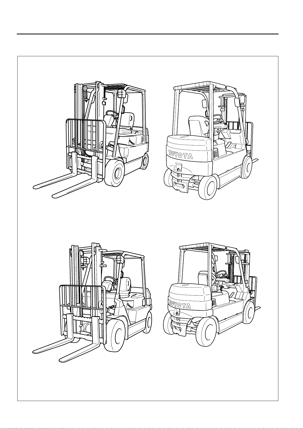
VEHICLE EXTERIOR VIEWS
MODEL LINE-UP
STANDARD EQUIPMENTS
........................................................................0-3
.....................................................0-4
..................................................0-2
0
1
2
3
4
5
6
7
8
9
1
11
1
1
0-2
VEHICLE EXTERIOR VIEWS
7FBMF16~35
7FBMF40~50
MODEL LINE-UP
0
2
3
Models
0-3
1 ton Series
2 ton Series
3 ton Series
4 ton Series
Frame number stamping
Model
7FBMF16
7FBMF18
7FBMF20
7FBMF25
7FBMF30
7FBMF35
7FBMF40
Capacity
(Load Center 500 mm)
1.6 ton 7FBMF16 FBMF16
1.8 ton 7FBMF18 —
2.0 ton 7FBMF20 FBMF20
2.5 ton 7FBMF25 FBMF25
3.0 ton 7FBMF30 FBMF30
3.5 ton 7FBMF35 —
4.0 ton 7FBMF40 —
4.5 ton 7FBMF45 —
5.0 ton 7FBMF50 —
Stamping Style
(Starting Number)
7FBMF18 10011
7FBMF25 10011
7FBMF35 10011
Model (80V or 72 V)
New Previous
Stamping Location
Stamp on LH & upper surface of front cross plate
0
1
2
3
4
5
6
7
8
9
7FBMF45
7FBMF50
7FBMF50 10011
1
11
1
1
0-4
STANDARD EQUIPMENTS
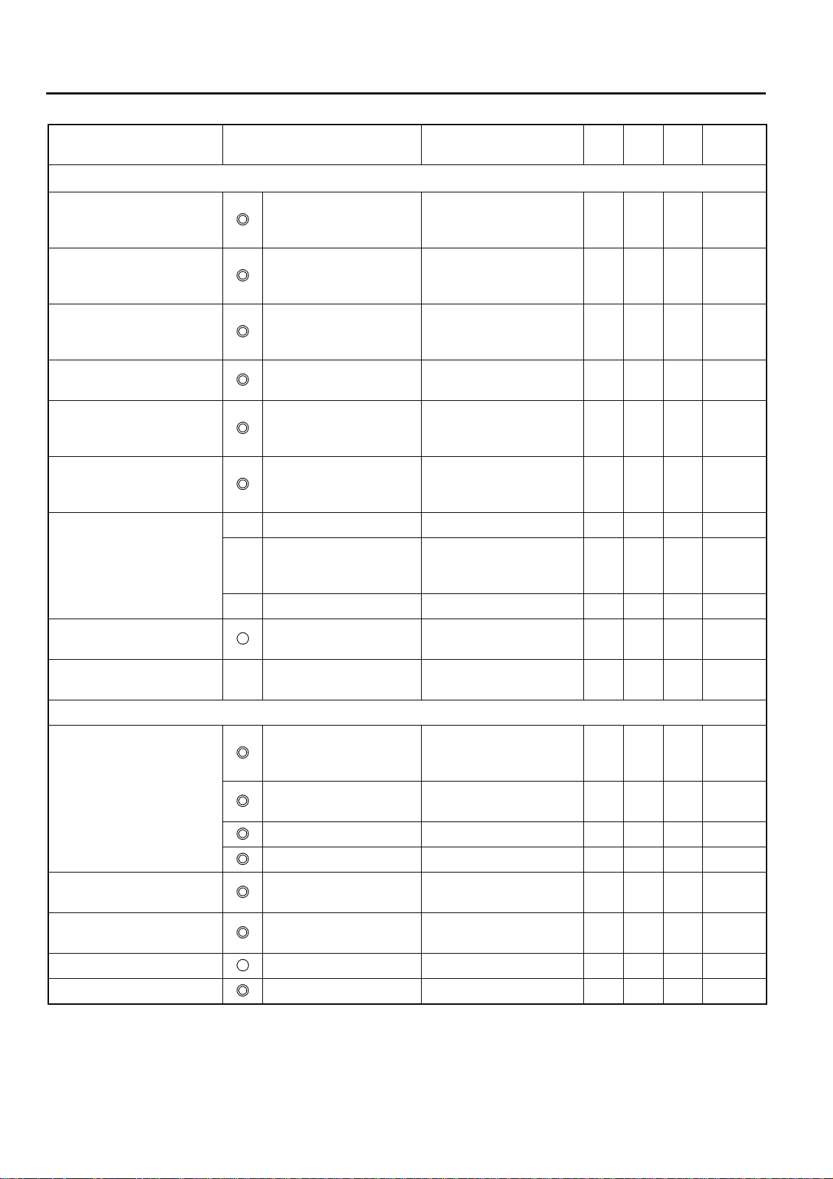
Standard Equipment 1.6-3.5 ton 4.0-5.0 ton Note
: STD P:OPT —: Not Available
Electrical
System
Chassis SAS (System of Active Stability)
Body Overhead guard
AC Power system for travelling & load handling
AC Power controller for steering — 1.6-3.5 ton: DC system
Multiple display (All round model) P P
Wet brake system
Parking brake system of electric switch type
Full hydraulic power steering
Memory tilt steering column
ORS seat
Floor mat
Battery hood damper
Assist grip (LH)
Instrument panel holder
Paper clamp on battery hood
Drawbar pin
Load
Handling
System
Others Electric horn
Wide visible mast (V) H3300 mm
Load bucharest H1220 mm
Fork 1.6~1.8 ton: L800 mm
Mini-lever control system
3-way valve (A400)
Headlight P P
Rear-view mirror P P
2.0~5.0 ton: L1000 mm

0
2
3
DEVELOPMENT OBJECTIVES
1-1
Page
DEVELOPMENT OBJECTIVES
FEATURES (SELLING POINTS)
AC POWER SYSTEM
................................................................1-6
..............................................1-2
............................................1-3
0
1
2
3
4
5
6
7
8
9
1
11
1
1

1-2
DEVELOPMENT OBJECTIVES
TOYOTA 1.6 ~ 3.0 ton FBMF 16 ~ 30 counterbalance type electric 4-wheel forklift trucks have had an established reputation as high performance forklift trucks since first their model launched in 1989.
There have been rising demands for clean electric forklift trucks with relevant to environmental concern; and further the market wants higher capacity forklift than 3.0 ton beside the existing capacity models.
Keeping these points in mind, the design concepts were established, as follows:
1. AC induction motor
Making best use of the advantages of AC induction motor drive system to respond to customer's needs for the
most suitable load handling system.
2. SAS - System of Active Stability
In order to gain better stability, SAS has been developed. SAS, adopted by 7 series, has already won high confidence from the industrial truck markets.
This same level of stability will be incorporated into the new 7FBMF 16 ~ 50 models.
3. Introducing larger capacity models of 3.5 ton and over in addition to new 1 ~ 3 ton capacity models to enhance the product range.
Creation of over 3.5 ton capacity models has been undertaken together with the model changes launched for 1
~ 3 ton capacity models.
Most of all, the AC induction drive motor system has been a pioneering endeavor having rallied our technological
powers for a successful introduction in our products. Excellent features inherent to AC induction motor have
been used to its full advantages with success.
Furthermore, varied demands for additional features have been implemented. Emphasis has been placed on
system design development such as the mini-lever system and the wet brake system, etc.
The 7FBMF 16 ~ 50 models certainly have outstanding features compared to other forklift models. On operation,
the differences are so obvious in fundamentals, performance, comfort, etc. New 7FBMF 16 ~ 50 models are
commendable as an epoch in new era.
FEATURES (SELLING POINTS)
0
2
3
Table of selling points
Selling point Function or Item Objective
Improved performance
mfr: manufacturer
: Newly adopted, : Improved
S: STD, P: OPT, –: Not available
1.5
~
3.5t
4.0 ~
5.0t
mfr A
Relative
page
1-3
0
Improvement in operation
hours and work cycles without
an operator noticing a decline
in performance
Availability of different power
modes for different needs:
H mode: High power mode
P mode: Power mode
S mode: Standard mode
Other customized modes are
available as well.
Improvement in ease of
getting on and 0ff
Increased leg space Expansion of foot space S S — 1-10
Improved serviceability AC motor Need for servicing motor
Reduced need for servicing
brake
Power keep function Better performance at a low
battery level
Power select function A touch on a switch selects
optimum power mode.
Load handling power
control
Improvement on operator comfort
The entry area has been
widened by installing the
battery under floor
Improved serviceability
Overheat protector Power is reduced
AC controller Need for servicing contactor
Thermal protector Output is reduced
Wet brake system Service life of brake system
Regenerative system
(accelerator off)
Ease of getting on and off
equivalent to the enginepowered model
brushes is eliminated.
automatically when motor is
overheated.
is eliminated.
automatically when
controller is overheated.
is prolonged
Service life of brake system
is prolonged.
SS—
S
S—
S
SS—1-10
SS—1-7
SS—
SS—2-2
SS—
SSS5-10
SSS2-5
1-8
2-2
1-11
2-2
2-5
5-2
2-5
5-2
1
2
3
4
5
6
7
8
9
1
11
1
1
Higher safety during servicing Jacking points under the
counter weight and frame
Jacking points indicated for
higher safety
SS—9-2
1-4
Selling point Function or Item Objective
Safety
1.6 ~
3.5t
4.0 ~
5.0t
mfrA
Relative
Page
Improved turning stability SAS-active control rear
stabilizer
Improved material handling
stability
Load collapse reduction SAS-active mast function
Operation error prevention for
lift lever
Large reduction of natural
drop and front tilt (1/3 of
previous values)
Easy monitoring of SAS
operation status
Availability of maximum travel
speed control
SAS-active mast function
controller (front tilt angle
control)
controller (rear tilt speed
control)
SAS-active mast function
controller (key-lift interlock)
SAS-active mast function
control (key-lift interlock)
SAS-operation monitor,
indicator lamp, and
diagnosis
Speedometer Large display easy to see S S — 3-4
Speed alarm Warning is given when
Speed limiter Sets limits to travel speed S S — 3-4
Rear wheel ground grip
force increased when
required
Controls front tilt angle for
high lifting, etc. S S — 11-10
Controls rear tilt speed for
high lifting, etc. S S — 11-10
Prevents unintended fork
lowering
Cuts off valve oil leaks
when the key switch is
turned OFF.
Easy recovery from SAS
faults S S — 3-2
travel speed exceeds
preset level.
SS—11-6
SS—11-10
SS—11-10
PP—3-5
Improved visibility High-mount rear
combination lamps
Forward view Super-wide visible mast Maintains advantages of
Operability, etc.
Easy operation SAS-active mast function
control (automatic fork
leveling control)
Steerage, load handling
lever, accelerator pedal
Mini-lever S S P 10-12
Anti roll back S S S 2-5
Improved traveling stability Regenerative system
(accelerator off)
Smooth and quick switchback
operation
Improved meter of screen Multiple display Legible display S S — 3-2
Battery roll out PP—12-3
AC motor and AC controller Quick switchback operation
Visibility of forklift truck from
surrounding area
internal width of wide mast.
Automatically sets the mast
vertical. S S — 11-12
Reduced operation power
Regenerative braking
equivalent to engine brake
without time lag
PP—9-6
SS—10-2
SS— —
SS—2-5
SS—2-5

Outline of Design
0
2
3
Major differences from previous models
1-5
Item New models Previous models
General Overhead guard
Motor Drive motor
Controller Traveling Main controller & traveling motor driver 1.6 ~ 5.0 ton
Brake
mechanism
SAS
equipment
Frame Overhead guard
Others Floor mat Equipped 1.6 ~ 5.0 ton Nothing 1.6 ~ 3.0 ton
height
Wheelbase 1420mm 1.6 ~ 1.8 ton 1360mm 1.6 ton
(72V/80V)
Pump motor
(72V/80V)
PS motor
(72V/80V)
Load handling Main controller & load handling motor driver 1.6 ~ 3.5 ton
SAS Controller of SAS
Steerage 1.6 ~ 3.5 ton Steerage controller 1.6 ~ 3.0 ton
Main brake Wet brake 1.6 ~ 5.0 ton Dry brake 1.6 ~ 3.0 ton 5-10
Parking brake Parking brake system of electric switch type 1.6 ~ 5.0 ton Parking brake lever of ratchet type 1.6 ~ 3.0 ton 5-13
SAS specifications SAS-active control stability
Clearance
Step height
Underclearance
Center of Wheelbase
(Without load)
Material handling lever Mini-lever with armrest 1.6 ~ 5.0 ton Manual lever on the front cowl 1.6 ~ 3.0 ton 10-12
Seat ORS seat with seat belt 1.6 ~ 5.0 ton Seat with seat belt 1.6 ~ 3.0 ton 8-4
AC: 12.0 / 13.3 kw 1.6 ~ 1.8 ton DC: 7.6 / 8.6 kw 1.6 ton
AC: 14.9 / 16.6 kw 4.0 ~ 5.0 ton — —
AC: 12.0 / 13.5 kw 1.6 ~ 1.8 ton DC: 11.5 / 13.0 kw 1.6 ton
AC: 16.9 / 18.6 kw 2.0 ~ 2.5 ton DC: 14.8 / 17.0 kw 2.0 ~ 2.5 ton
AC: 16.9 / 18.6 kw 3.0 ~ 3.5 ton DC: 16.5 / 18.5 kw 3.0 ton
AC: 22.8 / 25.4 kw 4.0 ~ 5.0 ton — —
DC: 1.0 / 1.1 kw 1.5 ~ 3.5 ton DC: 1.0 / 1.1 kw 1.5 ~ 3.0 ton
Same motor for PS as well as hydraulic oil
pump
includes the steerage control
Controller of main
includes the steerage control
Mast function control
• Front tilt angle control
• Rear tilt speed control
• Automatic fork leveling control
• Key-lift interlock
2195mm 1.6 ~ 1.8 ton 2160mm 1.6 ton
2195mm 2.0 ton 2180mm 2.0 ton
2215mm 2.5 ton 2180mm 2.5 ton
2215mm 3.0 ~ 3.5 ton 2275mm 3.0 ton
2310mm 4.0 ~ 5.0 ton — —
1580mm 2.0 ~ 2.5 ton 1505mm 2.0 ~ 2.5 ton
1725mm 3.0 ~ 3.5 ton 1650mm 3.0 ton
2080mm 4.0 ~ 5.0 ton — —
1055mm 1.6 ~ 3.5 ton 1030mm 1.6 ~ 3.0 ton
1075mm 4.0 ~ 5.0 ton — —
525mm
545mm
535mm 4.0 ~ 5.0 ton — —
90mm
110mm
150mm 4.0 ~ 5.0 ton — —
Applicable
model
4.0 ~ 5.0 ton — —
Traveling & load handling controller 1.6 ~ 3.0 ton
1.6 ~ 5.0 ton —
4.0 ~ 5.0 ton — —
——11-6
1.6 ~ 5.0 ton
1.6 ~ 1.8 ton 515mm 1.6 ton
2.0 ton
2.5 ton
3.0 ~ 3.5 ton 675 (2nd) /160 (1st) 3.0 ton
1.6 ~ 1.8 ton 110mm 1.6 ton
2.0 ton
2.5 ton
3.0 ~ 3.5 ton 225mm 3.0 ton
——11-10
540mm 2.0 ~ 2.5 ton
130mm 2.0 ~ 2.5 ton
Applicable
model
Relative
page
—
5-2AC: 15.4 / 17.1 kw 2.0 ~ 3.5 ton DC: 10.1 / 10.6 kw 2.0 ~ 3.0 ton
10-27
10-27
Section
2, 11
Section
9
—
0
1
2
3
4
5
6
7
8
9
1
11
1
1
1-6
AC POWER SYSTEM
AC system in industrial trend
Industries have already employed AC power system by making use of its features. Three major features are:
System design
advantages
Simpler and smaller
1
construction of motor
Three-phase AC control
2
realizes wider control
range.
Motor brushes and
contactors are
dispensed with.
3
Thereby industrial truck engineers worldwide have already been aware of the splendid features of AC power system to be implemented in electric forklift trucks.
New AC drive motor systems have been adopted not only in the smaller capacity models, but also in the larger
capacity models. This new system resolves the opposing factors between larger output necessity and compactness.
Product level
advantages
More powerful motor can
be used without
increasing size.
Wide control range offers
a higher performance
and operability.
Reduced maintenance
cost as the needs for
servicing motor brushes
and contactors are
eliminated.
Industry 1970 80 90
Machine tool
DC AC
Train
DC AC
Electric
Automobiles (EV)
Electric Forklifts
DC AC
DC
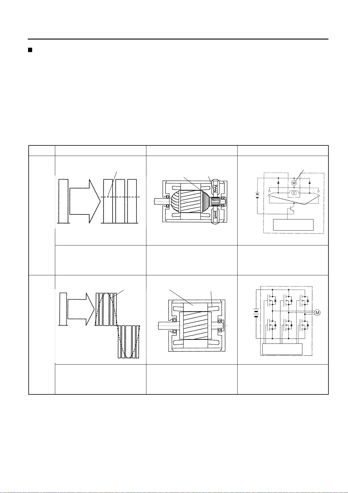
AC power system as compared with DC power system
In the DC power system the controller will chop the battery current in repetition and control the frequency
cycles of ON and OFF. The motor performance will change in proportion with the frequency cycles between
ON and OFF, thereby the inching at start to the max. performance is controlled.
The AC power system in the new models includes a controller that transforms the battery current into a threephase alternating current. The motor power is controlled by changing the sinusoidal waveform (frequency,
amplitude, etc.) of the three-phase alternating current.
Motor drive voltage, motor construction, and controller details differ between DC and AC power systems, as
follows:
Comparison between DC and AC power systems
Motor voltage Motor construction Controller
1-7
DC power
system
AC power
system
Mean voltage
ON
Controller
Battery
voltage
OFF
Mean voltage
• A chopper circuit converts the battery current (DC) into a rectangular
waveform and controls the mean
voltage at a desired level.
Sine wave
Controller
Battery
voltage
Motor
voltage
Commutator
Brush
• Brushes and commutator require
servicing.
• Complex mechanism
Stator ferrit core
Stator coil
Motor
Battery
Contactor
Microcomputer
control
• Motor power can be controlled simply via the mean DC voltage.
• Contactors for reversing the motor
rotation are required.
Battery
Motor
Microcomputer
control
• Controller converts battery current
(DC) into AC.
• Brushes and commutator, which require servicing, arer not used.
• Compact and lightweight
• A control module converts DC into
three-phase AC.
• Contactor for reversing the motor
rotation are not required.
1-8
Power keep function
(Functions in power mode: P, standard mode: S)
Power keep function using the benefit of AC power system further lengthen the operation hours epochally.
With conventional electric powered forklift trucks, the vehicle performance decreases gradually as the battery
level goes low.
The power keep function adopted to new models takes advantage of the increased controllability provided by
the AC system to keep the vehicle performance even when the battery level has become low. With this power
keep function, the maximum operating hours have increased by 25%, and the number of work cycles that can
be completed without the operator noticing a decline in performance has also increased by 25%.
New power keep function offers a significant and essential improvement in the material handling efficiency.
(See page 2-2 for further detail.)
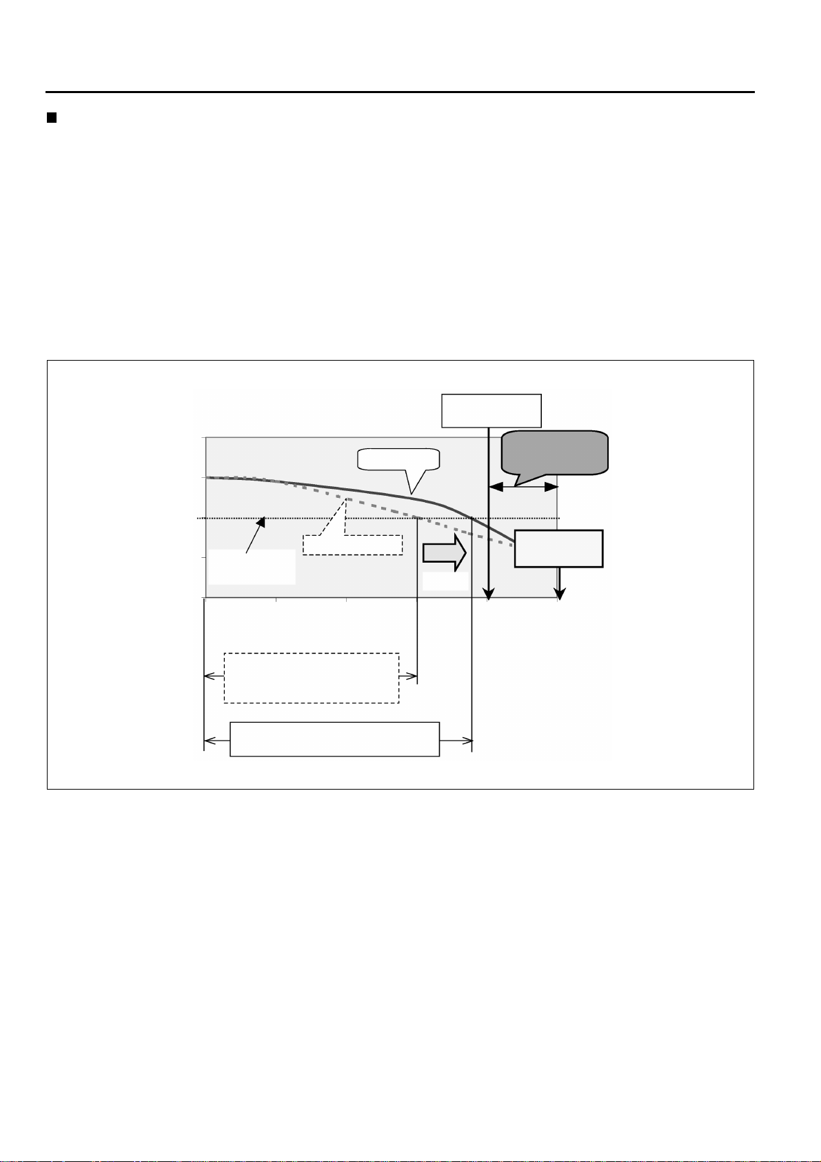
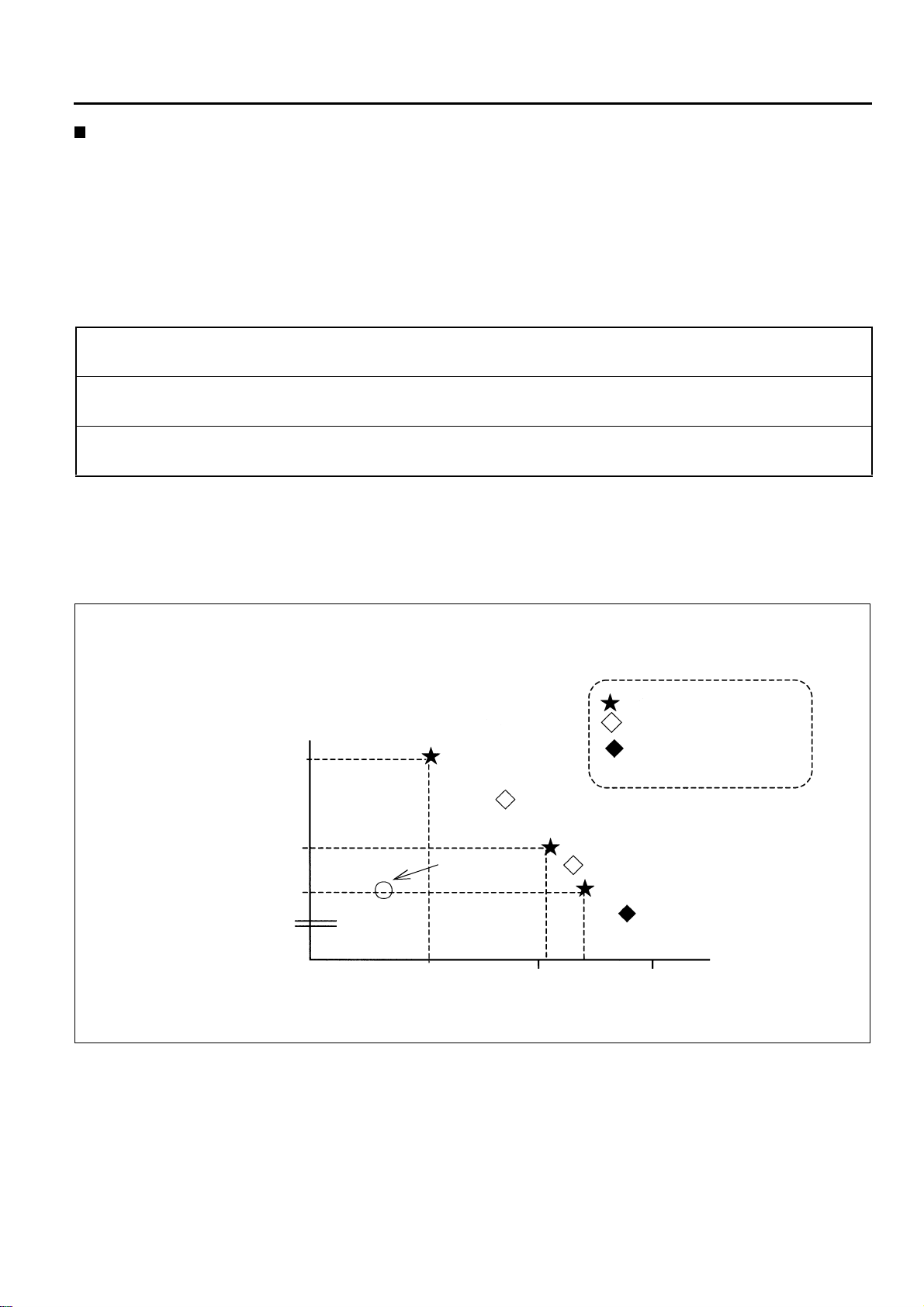
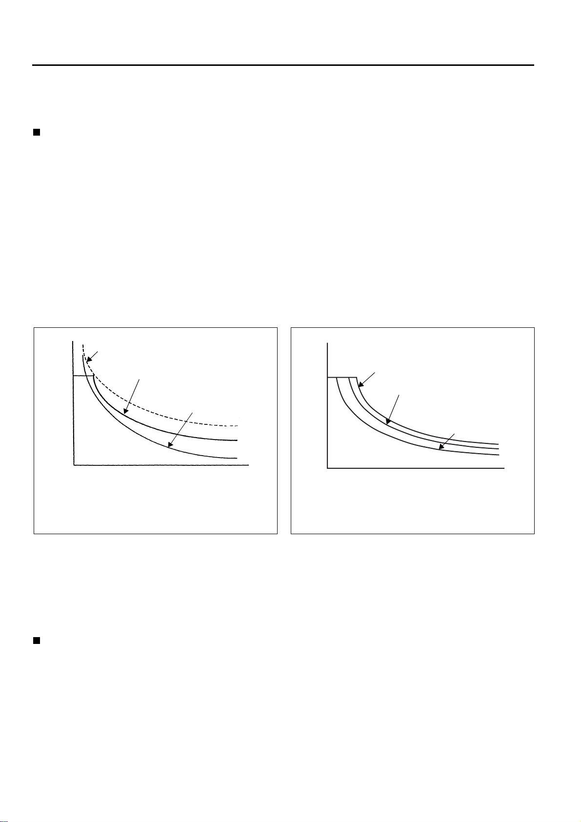
Battery discharge level and vehicle performance
Battery capacity
warning
1.1
New model
1
Battery usage
limit area
0.9
0.8
0.7
Decrease in
performance
0%
20% 40%
Battery discharge level (%)
Previous model (2.5 ton:S mode)
Efficiency operation hour:
161min
New model (2.5 ton:S mode)
Efficiency operation hour: 200min
Previous model
25% up
60%
Lift
interruption
80% 100%
Even the battery indicator is flashing to indicate the charge warning, the performance level of 7FBMF series is
batter than that of the former FBMF models.
In view of the battery protection, it is advisable to charge the battery before discharging to the limit.
1-9
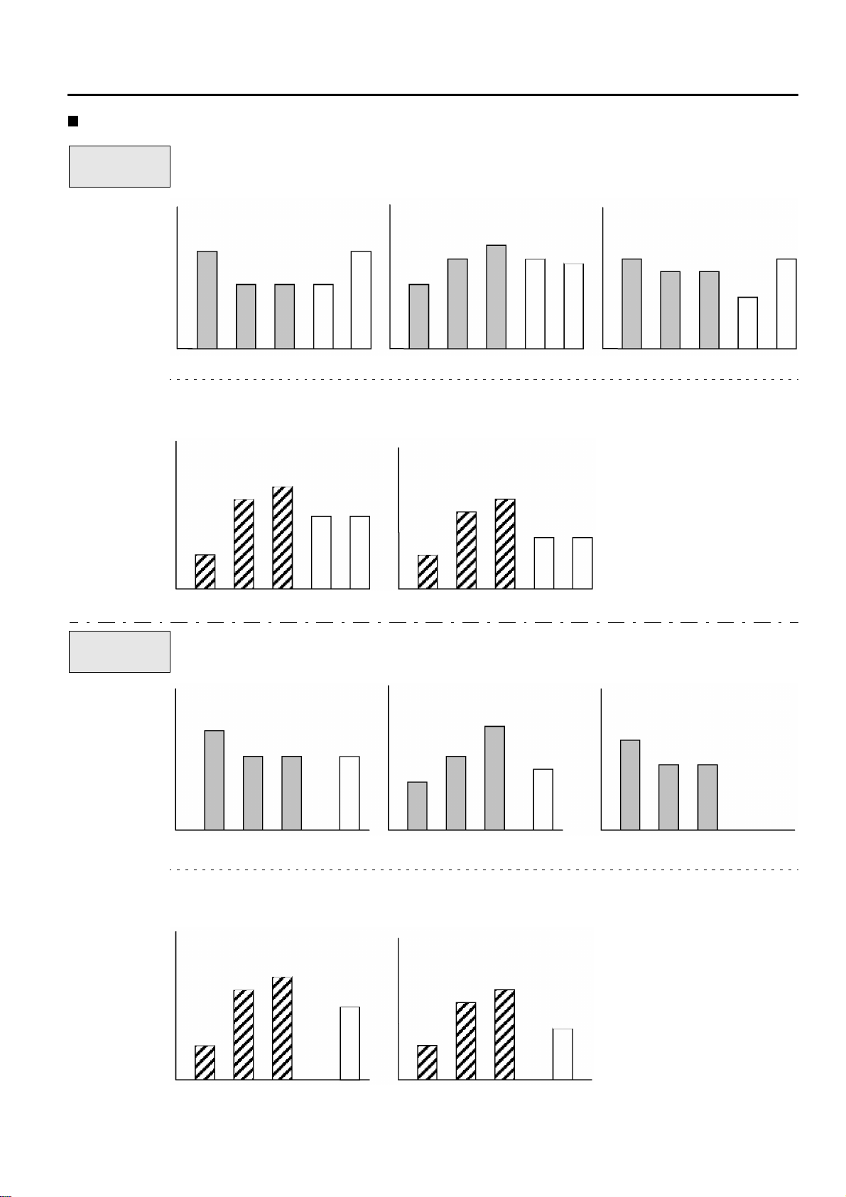
Performance features in comparison
2.5 ton
Traveling speed (km/h)
[a]
*: Loaded *Loaded: 0-10m
16
14
14
HPSFBMF
16
14
mfrA H P S FBMF
Efficiency operation hours (min)
[d] (Toyota 30m cycle)
*Battery 500Ah
200
185
163
161
125
Acceleration (sec)
[b]
5.7
5.3
4.6
No of cycle (cycle)
[e] (Toyota 30m cycle)
*Battery 500Ah
138
131
88
mfr: manufacturer
Slope climbing speed (km/h)
[c]
*Loaded: 1/10 slope
5.3
5.2
mfrA
111 112
6.9
HPSFBMF
5.6
5.6
7.0
5.3
mfrA
4.5 ton
HPSFBMF
Traveling speed (km/h)
[f]
*Loaded *Loaded: 0-10m
14
13 13 13
HPS
Efficiency operation hours (min)
[i] (Toyota 50m cycle)
*Battery 700Ah
218
204
133
mfrA H P S FBMF
Acceleration (sec)
[g]
5.9
5.4
mfrA
HPS
No of cycle (cycle)
[j] (Toyota 50m cycle)
*Battery 700Ah
174
96
67
6.3
100
5.7
mfrA
mfrA
Slope climbing speed (km/h)
[h]
*Loaded: 1/10 slope
4.8
3.4 3.4
HPS
80
HPS
mfrA
HPS
mfrA

1-10
Operator comfort
(1) Improvement of the ease of getting on and off
By new battery layout, improved the ease of getting on and off
(mm)
560
7FBMF
290
FBMF
260
mfrA
Entry clearance (2.5 ton) [a]
(2) Improvement of comfort
By new battery layout, improved the leg space
(mm)
640
7FBMF
604
FBMF
555
mfrA
Leg space (2.5 ton) [b]
1-11
Power select function
Using the power select function, the operator can select a desirable power mode.
Even though the conventional models also had a power selection switch, it only produced a small difference in
the acceleration.
New models use an AC motor instead of a DC motor.
Since and AC motor is simpler and smaller, it becomes possible to install a motor that produces an output higher
than that of a conventional DC motor.
In addition, the operator can select appropriate mode from the following power modes simply by operating a
switch.
• High power mode
: The most active mode with the quickest cycle-time
<H mode>
• Power mode
: The highest efficiency mode with quick cycle time and long operation hour
<P mode>
• Standard mode
: The longest operation hour mode with the performance equivalent to MFRA
<S mode>
In order to further satisfy the individual customer, a power select function has been provided.
The power select function enables the operator to select one from six power modes, including H, P and S modes,
for traveling. The operator can select H mode for operations requiring power and high performance. Select S
mode for long time operations, providing the operator with optimum performance to suit the operator’s needs
and greatly enhance efficiency.
<7FBMF25>
: Fixed mode
Cycles
44
High power mode
<H mode>
: Selectable only through
power select function
: Power select function
default setting
30m cycle pattern
43
42
41
Previous
model
Power mode
<P mode>
Standard mode
<S mode>
180min 240min
Efficient operation hours
1-12
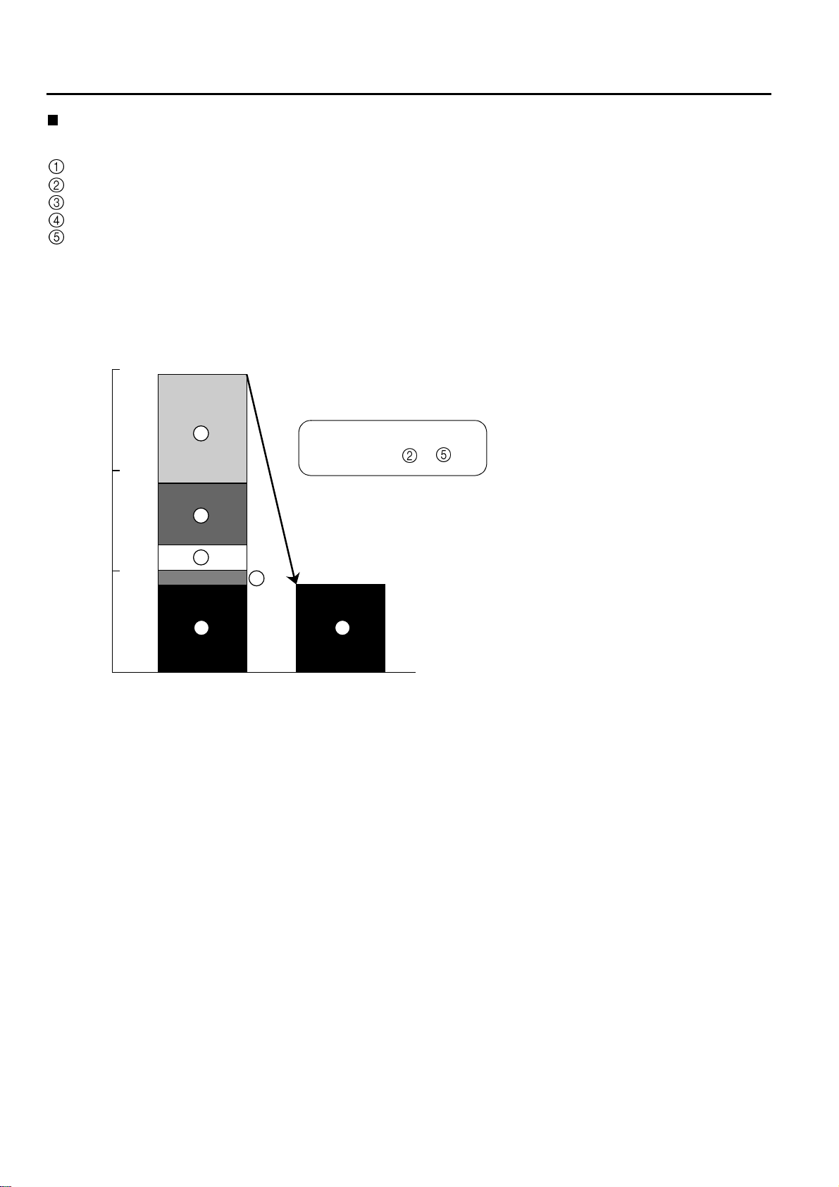
Reduced maintenance cost
The following particular items are inherent to the conventional electric powered models.
Supplying distilled water to the battery
Material handling motor brush replacement
Material handling motor contactor replacement
Traveling motor brush replacement
Traveling motor contactor replacement
The new 7FBMF model eliminates the need for brush and contactor replacement because the new AC motor
does not have brushes and the new AC controller does not have contactors.
The average customer can benefit from this by an annual cost savings of 69% for maintenance expenditures.
Eur (USD)
1500
519
1460 (1490)
5
1Eur = 0.98USD
Annual Cost Saving 69%
by Eliminating ~
1000
4
3
2
1 1
Previous
model
451 (460)
New model
500
294
127
69
451
0
Taking advantage of the wider control range of the AC power system, a regenerative system is adopted.
The AC induction motor generates a braking force when the vehicle is traveling with the accelerator pedal at rest.
Also the electromotive force generated in the AC motor, while the accelerator pedal is released, converts the
braking effect energy into electrical energy that is sent to the battery.
This regenerative system increases the operation hours. At the same time, the regenerative system improves
the traveling feel because it allows the operator to use less brake pedal force to slow the truck down. Furthermore, the regenerative system reduces load on the brake system, slowing down brake lining wear and decreasing the brake maintenance costs.

1-13
Stabilizing features
The world-first System of Active Stability (SAS), adopted by the 7FB series models, is available for the new models, too.
Using the SAS the new models achieve the stability level equivalent to that achieved by the 7FB series models.
The following outlines the SAS. For more details of the SAS option, refer to Section 11 “SAS”.
Stability feature Outline
Rear stabilizer (swing lock) The rear wheel swing mechanism is locked at high lift-heights and
heavy loads, and during a quick turn to obtain a better ground grip
force from all four wheels.
Mast function control
Front tilt angle control The front tilt angle is smaller at high heights and heavy loads;
greater at low heights and light loads.
Rear tilt speed control The rear tilt speed is slower at high heights and faster at low
heights.
Key-lift interlock The lift lever cannot function by inadvertent contact.
Automatic fork leveling control A push on a control button followed by a front tilt operation tilts the
mast until the forks are horizontal.
Improvement on operability
1. Mini lever
The hydraulic control levers are displaced to the arm rest fore-front and optimal length, and spacing are
given on basis of human engineering. An operator can manipulate the control lever with a hand on the
arm rest. Fine operation adjustment can be achieved with the display. The control lever position is adjustable vertically as well as to lengthwise.
Pleasant material handling operation with less fatigue can be ensured.
1-14
Anti-rollback
The anti-rollback function is provided to prevent the truck from rolling down on a slope. This is realized by making
use of the combined features of the drive motor electric brake and the parking brake.
Restarting can be done smoothly without rolling down.
Model line-up
The model line-up has been widened by the development to 3.5 ~ 5 ton class new model ranges; besides, the
1.8 ton model is added onto the 1 ~ 3 ton classes to meet with varied needs from the markets.
: New : Continuation
Capacity (kg)
1600 1800 2000 2500 3000 3500 4000 4500 5000
7FBMF
TOYOTA
FBMF

0
2
3
CONTROLLER
2-1
Page
MAIN CONTROLLERS
General
Controller Configuration Diagram
MAIN FEATURES OF CONTROLLER
.................................................................................2-2
.............................................................2-2
.............................. 2-3
0
.................................2-5
1
2
3
4
5
6
7
8
9
1
11
1
1
2-2
MAIN CONTROLLERS
General
AC system
The AC motor drive system controller has been provided with:
• Microcomputer-assisted travel inverter control (converts DC to three-phase AC)
• CAN (Controller Area Network) communication function between main controller and traveling/material handling controller.
• Communication function between multiple display and SAS controller.
This is a multi-functional controller with advanced electronics technology.
The controller offers the power select function and power keep function that take full advantage of the AC power
system.
Power select function: Allows the operator to select from three traveling modes, H (High power) mode, P (Power) mode, and S (Standard) mode.
Power keep function: Maintains a high performance level even when the battery level becomes low and increases stress-free operation hours. (Available when P or S mode is selected.)
AC motor maximum output
AC power system output
characteristics
Torque
DC power system output
characteristics (DC motor
maximum output)
Revolution
Compared to the DC motor, the AC motor has
higher output and a range of output characteristics is obtainable from the increased output.
Torque
When the battery is discharged, the AC motor
provides output characteristics closer to those of
a fully charged battery than a DC motor does.
AC and DC power system output
characteristics with fully charged battery
AC power system output
characteristics with discharged battery
DC power system output
characteristics with
discharged battery
Revolution
Compared with a DC motor of an equivalent size, an AC motor has a higher output.
The output characteristics of an AC motor are determined by the amplitude and frequency of the alternating current output by the controller.
The controller has a map stored in its memory of the optimum combinations of the current and frequency. Using
these, the optimum output characteristics can be obtained for all conditions. When the power selection switch is
operated, the controller switches the map and changes the output characteristics. The power select function thus
enables the output characteristics to be changed in accordance with the vehicle usage conditions.
Power keep function
With a DC power system, the output characteristics are determined by the controller output voltage. The maximum output, therefore, is the output from the motor when the battery voltage is fully applied (chopper duty
100%). The output will decrease with the battery voltage as the battery is discharged.
With an AC power system, however, it is possible to maintain a high performance even when the battery level
becomes low because the combination of the amplitude and frequency of the alternating current is changed as
the battery level goes low.
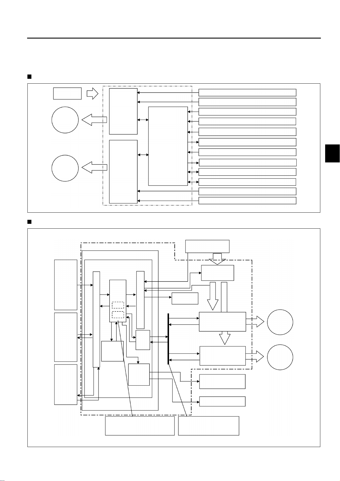
Controller Configuration Diagram
0
2
3
1. Traveling & Load handling controller
System configuration diagram
2-3
Battery
Traveling
motor
Traveling
AC motor
Material
handling
AC motor
driver
Main
controller
Material
handling
motor
driver
Traveling and material handling controller
Controller internal configuration diagram
Traveling and material handling controller
Main controller
CPU board
Traveling motor temperature sensor
Traveling speed sensor
Direction switch
Traveling accelerator potentiometer
Brake switch
Parking brake valve
Material handling potentiometer
Oil control valve
SAS(with PS) controller
Multiple display
Material handling motor temperature sensor
Material handling speed sensor
Battery
0
1
2
3
4
5
6
7
Sensors
and
switches
Multiple
display
SAS
(with PS)
controller
I
/
O
CPU
RAM
ROM
EEPROM
Comfortable operability is
realized by making fine control
using microcomputer.
I
/
O
CAN
I/O
Solenoid
drive
circuit
Cooling fan
Power supply
contactor
Traveling motor driver
Material handling
motor driver
Oil control valve
Parking brake valve
CANBus
Controller Area
Network Bus
Traveling
AC motor
Material
handling
AC motor
8
9
1
11
1
1
2-4
CPU: Central Processing Unit
ROM: Read Only Memory (with built-in control program)
RAM: Random Access Memory (memory content lost when power turned off)
EEPROM:Electrically Erasable Programmable Read Only Memory (memorizes data required for control and er-
ror code.)
I/O: Input/Output interface
CANI/O: Controller Area Network Input/Output interface
2. SAS (With Power Steering) Controller
System configuration diagram
Battery
Tire angle sensor
Wheel angle sensor
PS motor
PS circuit
Control circuit
Swing solenoid
Knob position correcting valve
Main controller
SAS (with PS) controller
Controller internal configuration diagram
SAS (with PS) controller
CPU board
I/O
Tire angle sensor
Wheel angle sensor
CPU
I
/
O
I
/
O
Yaw rate
sensor
Power & solenoid
drive board
Battery
Swing solenoid
Knob position
correcting valve
Main controller
*PS motor drive
main circuit
The portions marked with * are applicable only to 7FBMF 16 ~ 35 models.
CPU: Central Processing Unit
I/O: Input/Output interface
*PS motor

MAIN FEATURES OF CONTROLLER
0
2
3
1. Regenerative system (accelerator off)
When the vehicle travels with the accelerator off, a braking force produced by the motor generates electricity,
which is retrieved by the battery. The working of the regenerative system extends the available operation
hours and the service life of brake linings. At the same time, the regenerative system improves the travel
speed controllability and stability because it allows the operator to use the soft braking force exerted by the
motor. Even if the direction lever is at the neutral position, the regenerative system will function when the
accelerator is off.
2-5
2. Regenerative system (brake pedal depressed)
Regenerative system is operated when the brake pedal is depressed as well, which allows to extend the
available operation hours and the service life of brake lining.
Even if the direction is at the neutral position, the regenerative system will function when the brake pedal is
depressed.
3. Regenerative system (switch back)
The switch back operation (It means the directional change during traveling) also regenerate electricity like
the previous model. Furthermore the AC controller in the new model has no contactor for traveling so that
the switch back operates smoother than before.
4. Power select function
Three traveling and material handling modes are available from a selection switch on the multiple display: H
(high power) mode, P (power) mode, and S (standard) mode.
5. Advanced power select function (option)
The advanced power select function allows the operator to select a traveling power mode and a material handling power mode independently from each other. It also allows the operator to define a mode other than H,
P, and S.
6. Power keep function
The power keep function maintains the vehicle performance at a high level even when the battery level is
low. With the new models, stress-free operation hours for a battery charged have increased.
(The power keep function is available only when the operator selects P or S mode.)
7. Auto-off system
If the operator leaves the vehicle with the key switch ON, the auto-off system forcibly shuts down the controller (equivalent to key switch OFF) after a preset period to prevent wasteful expenditure of energy. To restart the vehicle, turn the key switch OFF and then ON.
0
1
2
3
4
5
6
7
8
9
8. Seat switch
The seat switch does not allow the vehicle to travel as well as any material handling to operate by the minilevers unless someone is on the operator's seat.
9. Anti-rollback function
The anti-rollback function makes it easy to start the vehicle on an inclined surface. This function is achieved
by controlling both the drive motor and the brake system.
10. 2-speed travel speed control
The 2-speed travel speed control switch sets a speed limit.
The set value is adjustable by a switch on the multiple display.
11. Thermal Protector
Overheat warning:
Temperature in the controllers and motors are monitored by temperature sensors. If an abnormally high temperature is detected, the controller output is reduced to prevent overheating. The display will warn the operator.
1
11
1
1

2-6
12. Battery level computation
The controller monitors decrease in the battery voltage, computes the remaining capacity, and displays it as
the current battery level.
13. Diagnostic function
The diagnostic function can detect abnormalities in the traveling controller and the material handling controller, operation mechanisms such as the accelerator, and sensors. When an abnormality is detected, the diagnostic function outputs a diagnostic code and takes the appropriate measure.
14. Analyzer function
The multiple display has an analyzer mode that can be used for troubleshooting or for testing operation
mechanisms and motor drivers.
15. Over-discharge warning function
When the remaining capacity level reaches a specified level, the multiple display shows a warning and the
load handling operation is restricted.
This will protect the battery and will urge the operator to charge the battery.
It is possible to release this restriction temporarily by turning the key switch off at once before resetting as
emergency measures.
16. Return-to-neutral function
If the operator turns the key switch ON with the direction lever at the forward or reverse position or with the
accelerator pedal depressed, the vehicle will not start. The operator has to return the direction lever and accelerator pedal to their neutral positions once in order to allow it to restart.
17. Parking brake ON warning
The buzzer sounds when the operator attempt to start the truck with the parking brake switch turned ON.
18. Parking brake OFF warning
The buzzer sounds to warn the operator when moving from the drive seat without the parking brake switch
turned on.
19. Mini-lever control
Based on operation signals of the mini-lever, the main controller controls material handling operation by controlling solenoid valves and the material handling controller.

0
2
3
MULTIPLE DISPLAY
3-1
Page
MULTIPLE DISPLAY INDICATION
MULTIPLE DISPLAY FUNCTIONS
SERVICE FUNCTIONS
.............................................................3-9
.......................................3-2
.......................................3-3
0
1
2
3
4
5
6
7
8
9
1
11
1
1
3-2
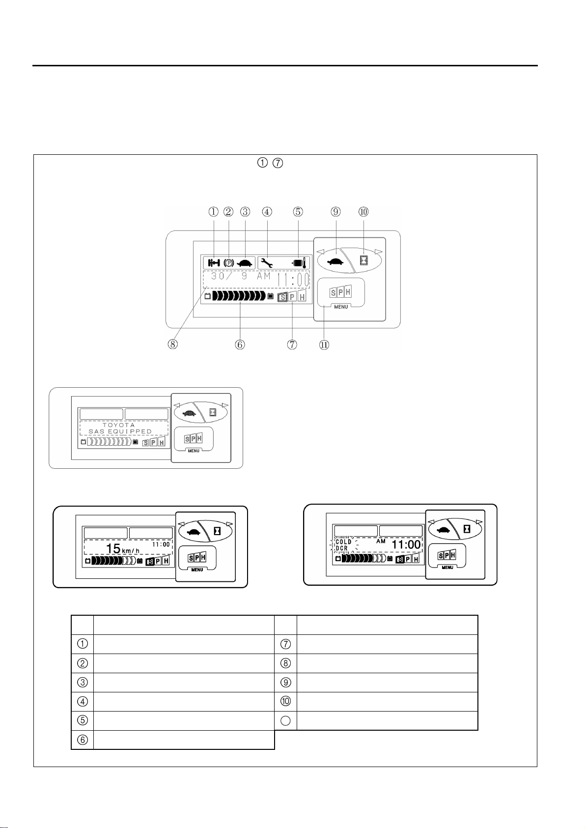
MULTIPLE DISPLAY INDICATION
General
Various essential data with regard to the truck status, warning signs, setting, meters, etc. are visible by switching
display.
(Indication of - will be changed according to the functional operation.)
During parking
Initial screen after the key switching on
During traveling
No. Description No. Description
Swing lock indicator Power select indicator
Upon error occurrence
Parking brake indicator Multiple display area
Travel 2nd speed setting indicator Travel 2nd speed control set switch
Diagnostic mode indicator Hour meter select switch
Overheat warning indicator Power select switch
Battery capacity indicator
11
MULTIPLE DISPLAY FUNCTIONS
0
2
3
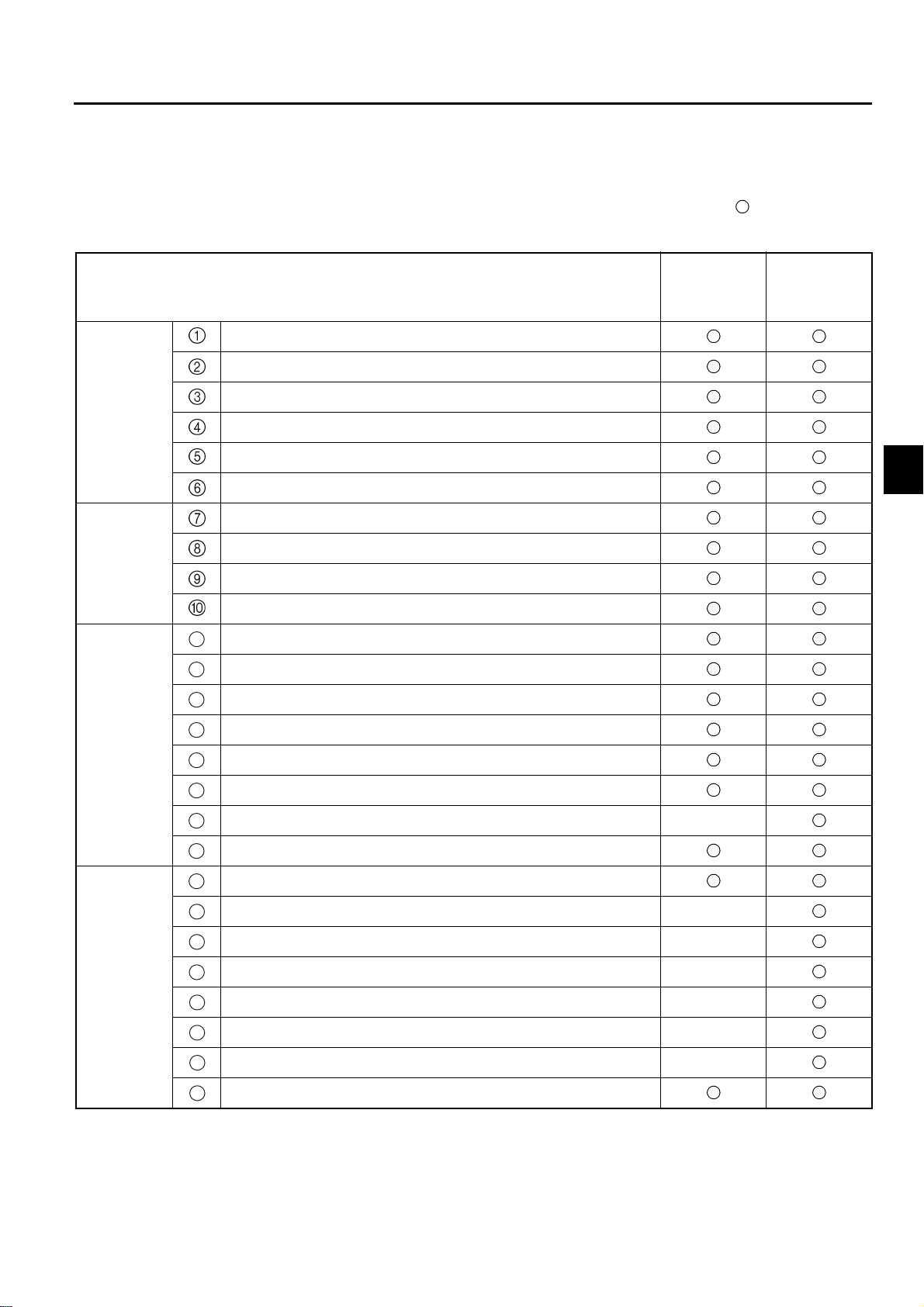
Table of Multiple Display Functions
3-3
: Available
—: Not available
Functions
Status
display
Level
setting
Battery capacity indicator
Speedometer
Travel 2nd speed setting indicator
Swing lock indicator
Parking brake indicator
Power select indicator
Power select function
Travel power control level setting
Material handling power control level setting
Travel 2nd speed control level setting
11
Battery over-discharge warning
Low battery capacity warning
12
13
Overheat warning
Easy model
(standard)
All-round
model
(optional)
0
1
2
3
4
5
6
7
Warning
Integrating
meters
Parking brake ON warning
14
15
Parking brake OFF warning
Return to neutral warning
16
17
Over speed alarm —
Diagnostic code display
18
19
Key switch on hour meter
Travel or material handling motors service hour meter —
20
21
Travel motor service hour meter —
Material handling motor service hour meter —
22
23
Lap time meter —
Odometer —
24
25
Trip meter —
Calendar/Clock
26
8
9
1
11
1
1

3-4
Explanation of list items
Easy model (standard) and all-round model
Difference between easy model (standard) and all-round model (option)
As shown in the table, all-round model (option) has additional optional meters, such as No. - .
20
25
Status display
The indications with regard to the existing condition (or Status quo) of the truck before or during the operation
Battery capacity indicator
Battery capacity indicator shows the remaining battery level in 10 stage mark.
Speedometer
Speedometer indicates speed digitally in 1 km/h.
When stopping, the part of the display of the vehicle speed shows the date and the clock, and only when
traveling, displays the vehicle speed.
Travel 2nd speed setting indicator
This indicator comes on or goes off whenever the operator presses the travel 2nd speed control switch. This
indicator is lit when the travel 2nd speed control is effect, limiting the vehicle speed at a preset level. The
speed control level can be set using the travel 2nd speed control level setup screen.
Swing lock indicator
This indicator is lit when the swing lock cylinder of SAS function is locked. This indicator goes off automatically when the swing lock cylinder is unlocked.
Parking brake indicator
The operation indicator blinks while the parking brake is in operation.
Power select indicator
It is a mode being enclosed with of S P H which has been selected now. Whenever the power select switch
is pushed, the select mode can be changed. When “POWER SELECT” is “YES” on the power control selec-
tion screen, all S P H is enclosed with .

3-5
0
2
3
Level setting
The level with regard to the manipulation and the performance can be selected and set up in compliance with
needs.
Power select function
Three traveling and material handling modes are available from a selection switch on the multiple display:
H (high power) mode, P (power) mode, and S (standard) mode.
Travel power control level setting
Setting becomes possible only when setting “YES” on the power control selection screen. The power control
level can be set besides the S P H mode.
0
Material handling power control level setting
Setting becomes possible only when setting “YES” on the power control selection screen. The power control
level can be set besides the S P H mode.
Travel 2nd speed control level setting
The travel 2nd speed set up and its cancellation can be done on the screen, and the maximum speed is restrained from exceeding by the set up speed.
Warning
Faults or risks can be detected and warning are given .
11
Battery over-discharge warning
If the battery is further discharged to another preset level after the low battery level warning has been given,
all segments in the battery level indicator blink and a buzzer sounds to warn the operator.
12
Low battery capacity warning
If the battery level goes below a preset level, the battery level indicator blinks. If the operator turns the key
switch from OFF to ON when the battery level is below this level, a buzzer will sound five seconds to warn
the operator.
Overheat warning
13
Overheat warning indicator blinks and a buzzer sounds to warn the operator when traveling motor, or material handling motor, and the controller overheats.
1
2
3
4
5
6
7
8
9
14
Parking brake ON warning
The buzzer sounds when the operator attempt to start the truck with the parking brake set.
15
Parking brake OFF warning
The buzzer sounds to warn the operator when moving from the drive seat without setting the parking brake.
16
Return-to-neutral warning
The buzzer sounds when the operator turns the key switch on while depressing the accelerator pedal or turning the direction switch on to start the vehicle.
17
Over speed alarm (option)
When the set speed is exceeded, it is detected and the speed indicator blinks and the buzzer sounds to give
a warning to the operator. Unlike travel 2nd speed control, even if the set speed is exceeded, any speed restriction is not applied.
18
Diagnostic mode indicator
This indicator blinks when the diagnostic mode operates, the error code is displayed, and the buzzer sounds.
1
11
1
1

3-6
Integrating meters (or multiple hour meter)
The indication differs between the easy model (standard) and the all-round model (option), as listed in the table
20
on page 3-3. The meter ~ are available to the all-round model.
In addition to the key-on-hours, the travelling and the material handling hours, and the travel distance can be
shown by total figures.
19
Key switch on hour meter
Total hours of the Key switch on time are shown
Travel or material handling motors service hour meter (option)
20
Drive motor running hours + (plus) material handling motor running hours are shown in total hours.
Length of time during which both motors are running, one motor only is counted.
21
Travel motor service hour meter (option)
Travel motor running hours in total are shown.
22
Material handling motor service hour meter (option)
Material handling motor running hours in total are shown.
Lap time meter (option)
23
Key on time in total during predetermined period is shown.
25
24
Odometer (option)
Travel distance in total is shown.
Trip meter (option)
25
Travel distance per trip is shown.
26
Calender / clock
See page 3-2 (Top drawing.)

Display screen list
<Initial screen>
Initial screen is displayed for a few seconds after key-switch ON.
<Normal function>
Press switch ........ Travel 2nd speed control ON and OFF
Press switch ........Hour meter screen
Press switch ........ Power select (S
Press switch ........for more than 2 seconds ... Next screen
→P→
H)
<Initial screen>
<Normal function>
The power select
switch is reset in the S
mode.
3-7
<Travel 2nd speed control level setting>
Press switch ........Decrease the set level
Press switch ........ Increase the set level
Press switch ........ Next screen
<Over speed alarm setting> All-round model (option) only
Press switch ........Decrease the set speed
Press switch ........Increase the set speed
Press switch ........ Next screen
<Power control setup selection>
Press switch ........Changes the setting from “NO” to “YES”
Press switch ........Changes the setting from “YES” to “NO”
Press switch ........Select “YES”
Travel power control
→
screen
Select “NO”
Next screen
→
<Travel 2nd speed
control level setting>
<Over speed alarm setting>
<Power control setup
selection>
- Continued -

3-8
<Clock setup selection>
Press switch ........ Changes the setting from “NO” to “YES”
Press switch ........ Changes the setting from “YES” to “NO”
Press switch ........ Select “YES”
Select “NO”
Clock set screen
→
Normal function screen
→
<Clock setup selection>

3-9
SERVICE FUNCTIONS
Multiple display has the service function to use when the serviceman maintain and set the specification of the
vehicle. Never to destroy important internal data by using the service function wrong, the service functions are
protected by the password.
Functions Description
Used for displaying the operation status of electrical systems
Analyzer
onboard or for accessing information on errors detected by the
controller.
Tuning
Option setting
Specifications
Availability of controls
Multiple hour meter
startup
Used for fine-tuning the traveling and material handing control
features.
Used for changing the setups according to the availability of
options.*
1
Used for changing the setups according to the availability of
various control features.
Used for starting up the multiple hour meter.
Used for setting and canceling the demonstration mode. (Function
Demonstration mode
prohibiting material handing operation during traveling which is set
at the time delivery.)
Matching
Wheel dia. (tire constant)
1
*
:
Used for readjusting the sensor signal voltage values associated
with the standard vehicle condition.
Used for improving the speedometer accuracy by updating the
wheel diameter information.
These functions are used to adjust the controller and display setups to the availability of optional or control features. They do not enable or disable the actual functioning of the optional or control features.

0
2
3
BATTERY
4-1
Page
SPECIFICATION
NECESSARY BATTERY WEIGHT
RECOMMENDED BATTERIES
BATTERY CONNECTOR RELEASE
BATTERY STOPPER
BATTERY INTERCHANGEABILITY
RECOMMENDED BATTERY LIST
TABLE OF WORKING HOURS
.........................................................................4-2
........................................4-2
..............................................4-2
................................................................4-3
........................................4-4
..............................................4-5
....................................4-2
.....................................4-3
0
1
2
3
4
5
6
7
8
9
1
11
1
1

4-2
SPECIFICATION
The batteries are not set up as TOYOTA genuine parts.
Use a battery compatible to DIN43 536 (See the battery case dimensions listed in the table on page 4-4).
Length
X
In case where high height battery type and battery roll out option are
selected, the battery case dimensions are different from the STD
type.
Use a battery attached with the intermediate tapping led.
Height
Z
Y
Width
NECESSARY BATTERY WEIGHT
When installing a battery, refer to the table on page 4-4. adjust the weight so that the necessary minimum weight
is satisfied.
RECOMMENDED BATTERIES
Refer to the table on page 4-4.
BATTERY CONNECTOR RELEASE
The battery connector release is the standard equipment in all the
models.
Since the battery connecter is located under the battery hood, it is
necessary to disconnect at the operator’s seat by the lever operation.

4-3
0
2
3
Note: Use a battery connector (320A, 50sq) compatible to DIN
43 589 with Auxiliary electrode (the recommended connector is FEM 320A made by REELS. The dimensions of
the hook is as illustrated. Don't use any other connector.
When a battery is installed locally, always check that
the connector can be released by the release lever.
BATTERY STOPPER
Newly designed battery stopper prevents the battery from coming
out, even if the truck should tip over. Always check that the stopper
is securely locked by the spring, as illustrated.
Where the high height type battery option or the battery roll out type
option is installed, always check that the battery hood is securely
locked, because the hoods prevent the battery from coming out
even if the truck should tip over.
48mm
Controller cover
127mm
0
1
2
3
4
5
Stopper pin
BATTERY INTERCHANGEABILITY
The dimensions of the battery case for the previous models are
equivalent to those of high height battery type option on the new
models. But in order to install the previous battery on the new model, it is necessary to change the battery connector and the cable
(160A, 35 sq
320A, 50 sq).
→
Spring
Battery guard
Battery caseStopper pin
6
7
8
9
1
11
1
1

4-4
RECOMMENDED BATTERY LIST
S
Vehicle type Voltage
7FBMF16,18 80 STD 4PzS440L
7FBMF20,25 80 STD 5PzS550L
7FBMF30,35 80 STD 6PzS660L
7FBMF
40,45,50
Battery
type
OPT
(High
height
battery
and
Battery
roll out)
OPT
(High
height
battery
and
Battery
roll out)
OPT
(High
height
battery
and
Battery
roll out)
80 STD 7PzS770L
OPT
(High
height
battery
and
Battery
roll out)
DIN No. Supplier Model
3PzS420L
4PzS560L
5PzS700L
6PzS840L
VARTA
OLDHAM
FULMEN
VARTA
OLDHAM
CHLORIDE
FULMEN
VARTA
OLDHAM
FULMEN
VARTA
OLDHAM
CHLORIDE
FULMEN
VARTA
OLDHAM
FULMEN
VARTA
OLDHAM
CHLORIDE
FULMEN
VARTA
OLDHAM
FULMEN
VARTA
OLDHAM
FULMEN 80 v 6EPSZ 930 930 ↑↑↑ ↑
DNA4(4PzS480Hx) 480 ↑↑↑ ↑
DNA55(PzS600Hx) 600 ↑↑↑ ↑
DNA6(6PzS720Hx) 720 ↑↑↑ ↑
DOA5(5PzS750Hx) 750 ↑↑↑ ↑
DNA7(7PzS840Hx) 840 ↑↑↑ ↑
DOA6(6PzS900Hx) 900 ↑↑↑ ↑
Installed battery Battery case Necessaey minimum battery weight
Capacity
[AH/5hr]
4PzG400 400 708 1026 627 1220
4PzS440L 440 ↑↑↑ ↑
4PzS480Hx 480 ↑↑↑ ↑
DPA4 400 ↑↑↑ ↑
80 v 4EPSZ 460 460 ↑↑↑ ↑
80 v 4EPSZ 500 500 ↑↑↑ ↑
3PzG360 360 567 1028 784 1240
3PzS420L 420 ↑↑↑ ↑
3PzS450Hx 450 ↑↑↑ ↑
DZA3 390 ↑↑↑ ↑
DOA3 450 ↑↑↑ ↑
WESD7 360 ↑↑↑ ↑
WFSD7 450 ↑↑↑ ↑
SDH3 360 ↑↑↑ ↑
EGX3 450 ↑↑↑ ↑
5PzG500 500 852 1026 627 1530
5PzS550L 550 ↑↑↑ ↑
5PzS600Hx 600 ↑↑↑ ↑
DPA5 500 ↑↑↑ ↑
80 v 5EPSZ 575 575 ↑↑↑ ↑
80 v 5EPSZ 625 625 ↑↑↑ ↑
4PzG480 480 711 1028 784 1560
4PzS560L 560 ↑↑↑ ↑
4PzS600Hx 600 ↑↑↑ ↑
DZA4 520 ↑↑↑ ↑
DOA4 600 ↑↑↑ ↑
WESD9 480 ↑↑↑ ↑
WFSD9 600 ↑↑↑ ↑
SDH4 480 ↑↑↑ ↑
EGX4 600 ↑↑↑ ↑
6PzG600 600 996 1026 627 1780
6PzS660L 660 ↑↑↑ ↑
6PzS720Hx 720 ↑↑↑ ↑
DYA6(6PzS660L) 660 ↑↑↑ ↑
80 v 6EPSZ 690 690 ↑↑↑ ↑
80 v 6EPSZ 750 750 ↑↑↑ ↑
5PzG600 600 855 1028 784 1860
5PzS700L 700 ↑↑↑ ↑
5PzS750Hx 750 ↑↑↑ ↑
DZA5 650 ↑↑↑ ↑
WFSD9 600 ↑↑↑ ↑
WFSD11 750 ↑↑↑ ↑
EGX4 600 ↑↑↑ ↑
EGX5 750 ↑↑↑ ↑
7PzG700 700 1140 1034 627 2030
7PzS770L 770 ↑↑↑ ↑
7PzS840Hx 840 ↑↑↑ ↑
DYA7(7PzS770L) 770 ↑↑↑ ↑
80 v 7EPSZ 805 805 ↑↑↑ ↑
80 v 7EPSZ 875 875 ↑↑↑ ↑
6PzG720 720 999 1028 784 2180
6PzS840L 840 ↑↑↑ ↑
6PzS900Hx 900 ↑↑↑ ↑
6PzS840L 840 ↑↑↑ ↑
Dimensions[mm] Dimensions[kg]:With case
Length Width Height

TABLE OF WORKING HOURS
0
2
3
Table of Working Hours (S-Mode)
4-5
Model
7FBMF16 80, (72)
7FBMF18 80, (72)
7FBMF20 80, (72)
7FBMF25 80, (72)
7FBMF30 80, (72)
7FBMF35 80, (72)
7FBMF40 80, (72)
Battery Voltage
(V)
Battery Capacity
(AH/5hr)
400 4 h 30 min.
480 5 h 40 min.
400 4 h 20 min.
480 5 h 25 min.
500 4 h 55 min.
600 6 h 00 min.
500 4 h 30 min.
600 5 h 35 min.
600 5 h 35 min.
720 6 h 50 min.
600 5 h 15 min.
720 6 h 30 min.
700 5 h 05 min.
840 6 h 15 min.
Working Hours
( h min. )
0
1
2
3
4
5
6
7FBMF45 80, (72)
700 4 h 50 min.
840 6 h 00 min.
700 4 h 30 min.
7FBMF50 80, (72)
840 5 h 35 min.
Note:
1. Working Hours
7FBMF16 ~ 35 : TOYOTA 30m operation cycle
7FBMF40 ~ 50 : TOYOTA 50m operation cycle
2. Working Hours of H-Mode
1 ton Series : about 65% down of S-Mode
Above 2 ton model : about 73% down of S-Mode
3. Working Hours of P-Mode
All model : about 92% down of S-Mode
7
8
9
1
11
1
1

0
2
3
POWER TRAIN
5-1
Page
DRIVE MOTOR
DRIVE UNIT
FRONT AXLE
BRAKE
PARKING BRAKE
PARKING BRAKE SYSTEM
BRAKE PEDAL
........................................................................................5-10
............................................................................5-2
.................................................................................5-7
..............................................................................5-9
....................................................................5-13
.........................................................................5-17
.................................................5-15
0
1
2
3
4
5
6
7
8
9
1
11
1
1

5-2
DRIVE MOTOR
General
1. The new models use a newly developed AC induction motor as the drive motor. Being compact, powerful,
and maintenance-free, the new motor has ideal characteristics for a motor used in a battery-powered forklift
truck.
2. Since the new motor is so compact, it provided enough space under the floor to install the battery. With the
battery installed under the floor, the new models incorporate improvements in the ease of getting on and off
of the vehicle and operator comfort.
3. The new motor is maintenance-free; it does not have brushes that have to be serviced.
Drive unit
Field core
Rotor
Field winding
Speed sensor bearing
Drive motor characteristic
The newly developed AC induction motor characteristics are as follows:
• The motor is directly installed to the drive unit case (semi-built-in structure). Consequently, the drive motor as-
sembly is very compact.
• Optimized motor core form and coils have improved the motor efficiency.
• High-precision rpm sensors have been adopted to directly detect revolving speed, realizing power selection
function, power keep function and other fine-textured functions.
• The motor temperature detection sensor has been adopted to alert the controller and prevent the motor from
overheating during overloaded operation.
Note: The truck performance may go down temporarily under the severe use condition such as contin-
uous operation with a heavy load. The performance decline at the time is not at all abnormal since
it has been so arranged that the controller and the motor can be prevented from overheating.
The temperature sensors incorporated in the controllers as well as the motors detect the temperature rise, and the control by which current supply toward the motors has undergone restriction
will take place. On the occasion the monitoring display shows where subjected to overheat.
In the event of the overheat indication, wait the truck operation for a while until the display indication has gone away.

Main specifications
0
2
3
5-3
7FBMF16,18 72/80 12.0/13.3 Three phase AC
7FBMF20,25,30,
STD
7FBMF40,45,50 72/80 14.9/16.6 Three phase AC
Models
35
Nominal
voltage (V)
72/80 15.4/17.1 Three phase AC
Drive unit
Rated output
(kW)
Length
Rotor
Type
Body size
Diameter × Length (mm)
270 × 260 62
φ
270 × 285 73
φ
270 × 340 96
φ
Field winding
Weight
(kg)
0
1
2
3
4
5
6
Field core
Diameter
Speed sensor bearing
7
8
9
1
11
1
1

5-4
Structure and principle of AC induction motor
AC induction motor has no brushes, commutator and the sliding portion as opposed to the conventional DC motor.
Consequently it has the following characteristics:
1. For the same output, the motor dimensions can be reduced by the portion L for the brushes and commutator.
2. For the same motor dimensions, core dimensions can be increased by the portion L, subsequently increasing
the output.
3. Smaller number of parts and no sliding portion make the motor highly reliable.
An optimum AC induction motor has been developed for new models by incorporating these characteristics.
Induction motor Previous motor (DC motor)
Commutator
(Sliding portion)
L
Field core
Field winding
Rotor
Field winding
Rotor
Field core
Brushes
A rotor assembly consists of a number of identical aluminum conductor bars sunk into slots in a laminated steel
core, and the end rings that combine both ends of the conductor bars on the sides of the core as shown. Since
the bars and the end rings form like a cage for a squirrel or mouse, it is called a cage rotor.
Core
Rotor assembly
End ring
Cage rotor
Slots in a laminated
steel field core
End ring
Aluminum conductor bar

5-5
0
2
3
Operational sequence
1. The current flows in a fixed direction in the field winding in the figure. Magnetic field is produced around the
field winding in the illustrated direction according to the right-hand rule*, and magnetic poles (N-pole and Spole) are generated.
2. Now suppose that the magnetic poles are rotated clockwise. Then the bar of the rotor is considered to be
rotated to the counterclockwise direction.
3. Now, according to the Fleming’s right-hand rule*, electro motive force is generated to the bar of the rotor in
the illustrated direction.
4. Because of the electro motive force generated to the bar of the rotor, a clockwise force is generated to the
bar according to Fleming’s left-hand rule.*
5. Thus rotational torque is generated by electromagnetic force. The rotating speed of rotor is slightly slower
than the revolution of the field pole.
0
1
6. Actually, the field winding on the periphery is not moving. Sine wave from each phase of the three-phase
alternating current produces rotating magnetic field, generating torque to the rotor.
Field winding
Direction of current
Direction of
current induced in
the bar
Current
direction
Rotor (field winding)
Field winding
Direction
of force
Rotational
direction of pole
N pole
Magnetic
field
S-pole
: Current flow from the rear to the front
: Current flow from the front to the rear
Rotational
direction of pole
Direction
of force
Rotational
direction of cage
rotor
Magnetic field
Magnetic
field
Rotational direction of
Magnetic pole
2
3
4
5
6
7
8
9
1
11
1
1
* See the next page.

5-6
Operating principle of motor
Before explaining the operating principle of motor, Ampere’s right thread rule and Fleming’s rule will be explained.
1. Right handed screw rule
Extend the thumb of the right hand and close the fingers. If you
point the thumb in the direction of current flow as illustrated, the
magnetic field is produced at right angle to the current direction
and in the direction of the closed fingers.
Magnetic
field
Magnetic
field
Direction of
current
Direction of
current
2. Fleming’s right-hand rule
Arrange for a fixed object on which a linear object can freely
move as shown. In this state, when the magnetic field is produced in the illustrated direction, moving the linear object in the
illustrated direction produces current. The direction of current is
as illustrated:
3. Fleming’s left-hand rule
Arrange for a fixed object on which a linear object can freely
move as shown. In this state, when the magnetic field is produced in the illustrated direction, current flowing in the fixed object causes a force acts on the linear object in the illustrated
direction.
Direction
of current
Direction of
magnetic field
Magnetic field
Direction
of motion
Direction of
current
Magnetic field
Direction
of motion
Direction of force
Direction of
magnetic field
Magnetic field
Direction
of force
Direction
of current
Direction
of current
Magnetic field

DRIVE UNIT
Features
1. The drive unit has been changed, as follows:
5-7
Previous models
4-axes, 3-stages speed reduction
2. The parking brake has been set up on the drive motor shaft due to the adoption of the wet brake.
3. New models like the previous models, the drive motor has been installed to the drive unit in “Semi-built-in
structure”, on a parallel to the front axle.
4. New models, like the previous models, use the liquid gasket (FIPG) to obtain high sealing effect on the drive
unit housing.
5. As the lubricant, use the gear oil suitable for the wet brake.
Note: Use gear oil only TOYOTA specified:
SHELL DONAX TD
6. New models like the previous models, helical gear having high transmitting efficiency has been adopted to
all the gears.
7. Gear ratio table
New model Previous model
1-ton Series 89/16 × 54/11 = 27.307 52/23 × 62/33 × 45/12 = 15.929
3-axes, 2-stages speed reduction
New models
2-ton Series 96/15 × 60/11 = 34.909 52/23 × 62/33 × 45/12 = 15.929
3-ton Series 96/15 × 60/11 = 34.909 56/19 × 62/33 × 45/12 = 20.766
4-ton Series* 88/15 × 51/19 = 15.747 —
* Without wheel reduction

5-8
Drive unit sectional view
Third axle
(front axle center)
Second axle
(pinion shaft)
First axle
(motor input shaft)
Parking brake

5-9
FRONT AXLE
Difference between previous models and new models
The axle housing and the axle brackets are integrated, and bolted to the drive unit housing. The reactive force
vs. the drive-force and the brake effects will be received by the axle bracket mount bolts.
Type of front axle
Semi floating type front axle design has been used for all the models. 7FBMF40, 45 and 50 models use planet
gears between the tires and the differential gears.
Front axle (1.6 ~ 3.5 ton)
Axle shaft
Axle shaft
Front axle (4.0 ~ 5.0 ton)
Axle bracket
Axle bracket
Planet gear

5-10
BRAKE
Difference between previous model and new model
The wet brake has been adopted in place of the dry brake with the result that reliability and durability have been
considerably improved, especially against water and mud.
Besides the brake has become free from worn particles out of the brake lining.
Dry brake
Brake disc
Wet brake (1.6 ~ 2.5 ton)
Brake piston
Wet brake (3.0·3.5 ton)
Brake specification
Item 1.6 ~ 1.8 ton 2.0 ~ 2.5 ton 3.0·3.5 ton 4.0 ~ 5.0 ton
Brake lining dimensions
(thickness × outside dia. × inside dia.)mm0.5 × 221 × 150
Brake disc
Wet brake (4.0 ~ 5.0 ton)
←←
0.8 × 276 × 200
Brake pistion
Quantity of brake disk 2 × 2 2 × 2 3 × 2 1 × 2
Brake & drive unit oil SHELL DONAX TD

Brake valve
The full power type brake valve has been adopted for all the models (1.6 to 5.0 ton capacity).
Specification of valve
Item 1.6 ~ 5.0 ton
Type Full power CHPS
Fluid used ISO VG#32
1.6 ~ 3.5 ton
From oil
pump
To oil tank
5-11
4.0 ~ 5.0 ton
To front brake
To front brake
To PS
From oil
pump
To PS
To oil tank

5-12
Note:
1. Lubricant for brake
For the lubrication of the brake discs as well as for the drive gearing, the same oil are used, since the
wet brake discs are dipped in gear oil.
Only TOYOTA specified oil must be used.
TOYOTA Specified oil: SHELL DONAX TD
It must be strictly forbidden to use the oil other than those specified by TOYOTA or oil mixed with
another since it will give the adverse effect, such as the brake mal-function and the noise occurrence.
2. Service for brake life
In case that the brake has become ineffective or noise should arise, the deterioration of the gear oil
and the brake discs can be suspected as the possible causes.
At the time, the gear oil should be renewed at first. If it is still ineffective, wearing down of the brake
discs can be considered. Then the brake discs should be renewed together with the gear oil.
3. Washing
It must be strictly avoided to splash water round the breather (or bleed) plug while washing the truck
since water will penetrate into gear oil through the breather plug.

PARKING BRAKE
The wet disc parking brake has been adopted for all the models (1.6 ~ 5.0 ton).
Specification (for all the models)
Item 1.6 ton ~ 5.0 ton
5-13
Parking brake lining dimension
0.45 × 136 ×105
Thickness × Outside Dia. × Inside Dia.
Quantity of discs 2
Parking brake oil SHELL DONAX TD
Function
• Newly designed parking brake system differs from the previous system in that the parking brake force arises
when the brake discs are compressed on the motor shaft through the piston pressed by the conical disc
springs.
• On turning the parking switch ON, the solenoid valve releases oil in the chamber ‘A’ so that the force of the
conical disc springs will apply the brake.
• On turning the parking switch OFF, pressurized oil is fed to the brake housing from the PS pump through the
solenoid valve. Then the conical disc springs are compressed throgh hydraulic pressure so that the brake will
be released.
A
Piston
Disc
Conical disc spring
Drive motor

5-14
Parking brake switch
• The parking brake system is actuated by the electrical selector switch as illustrated:
Turn it to the right:
Parking brake on
Turn it to the left:
Parking brake release
Note:
• Always stop the truck and turn on the parking brake switch (turn to the right) to engage the parking
brake before getting off the vehicle.
Check to confirm that the parking brake is engaged.
• Never turn off the key switch unnecessarily while traveling, because it will cause the truck a sudden
stop with a shock.
• Never pull off the battery plug while traveling (except in case of emergency), because it will cause the
truck a sudden stop with a shock.
• It is impossible to release the parking brake if the power steering pump should stop supplying the
parking brake with pressurized oil; therefore, in case that the traction of the truck is in urgent need,
the parking brake cover plug should be removed to release the parking brake manually with a specified
tool (bolt).

PARKING BRAKE SYSTEM
Main controller
Brake change
valve solenoid
ON/OFF
SOL
Pump motor for steering
(7FBMF15~35)
Pump motor
(7FBMF40, 45&50)
To steering valve and oil
control valve
Brake
change
valve
Oil pump
5-15
Parking
brake
ON
OFF
Electrical signal
Key SW
Seat SW
Parking SW
Direction SW
Accelerator SW
Hydraulic line
Function
1. The parking brake will be released when it receives oil pressure from the brake change valve.
When it does not take oil pressure, it becomes the condition that a parking brake piston is pressed by the
cone spring, and the parking brake is effective.
2. The brake change valve changes an oil way to the parking brake by the solenoid valve.
Solenoid ON: The parking brake is released as it makes the oil way to the parking brake opened.
Solenoid OFF: The parking brake is applied as it makes the oil way to the parking brake closed.
3. The motor (The PS motor for 1.6 to 3.5 tons models and the pump motor for 4.0 to 5.0 tons models) starts
driving when both the key switch and the direction switch are turned on.
Then, oil pressure will arise from the oil pump directly connected to the motor.
4. The main control controller controls the solenoid valve by the signals from each switch.
Note: The traveling speed sensor which detects the traveling condition of the vehicle also has relation
to the parking brake system through the traveling controller.

5-16
5. To try to travel the vehicle makes the parking brake released.
When all the following conditions are satisfied, the parking brake is released by turning on the solenoid valve.
• Turning on the key switch
• Turning on the seat switch (The seated condition)
• Shifting the parking switch left (Release side)
• Turning on the direction switch (Forward or Reverse)
• Switching on the accelerator (Depressing the accelerator pedal)
In reverse, either of the following manipulation makes the parking brake operated by changing the solenoid
from ON to OFF.
• Turning off the key switch
• Shifting the parking switch right (Parking side)
When the switch other than mentioned above is turned off, the parking brake is not actuated at once but controlled as the following items 6, 7 and 8.
6. When a foot is left from the accelerator pedal during traveling, the parking brake is applied from 10 seconds
later after an electric brake acts and the vehicle stops completely.
And, it is the same when the direction lever is made a neutral position during traveling.
7. Brake control on a slope
If the accelerator pedal is released with the neutral direction lever position after the vehicle stops on the slope
once, the electric brake (the regenerative brake) works for 10 seconds to prevent the truck from going down,
and then it makes the parking brake acted in place of the electric brake.
8. If the seat switch is turned off during traveling, the controller considers the condition as an emergent situation,
and it makes the parking brake acted by changing the solenoid valve from ON to OFF as soon as the vehicle
stops by the electric brake.

5-17
BRAKE PEDAL
• 1.6 ~ 3.5 ton
New models use the pendent type brake pedal in place of the step down type brake pedal on the previous
models.
• 4.0 ~ 5.0 ton:
The pendent type brake pedal and the double link mechanism have been adopted.
Regenerative sensor
The limit switch has been adopted for reliability as that of the previous model, and sensing ability has been improved.
When the readjustment is required for the regenerative brake, service accessibility is good.
Sensor for Regenerative brake
Sensor for Regenerative brake
Brake pedal
Brake valve
Brake pedal (1.6 ton ~ 3.5 ton)
Brake pedal
Brake valve
Brake pedal (4.0 ton ~ 5.0 ton)

0
2
3
STEERING & REAR AXLE
Page
STEERING .......................................................................6-2
REAR AXLE (1.6 ~ 3.5 ton model) .................................6-5
6-1
REAR AXLE (4.0 ~ 5.0 ton model) .................................6-7
0
1
2
3
4
5
6
7
8
9
1
11
1
1

6-2
STEERING
1.6 ~ 3.5 ton
Power steering system
New models like the previous models have adopted Electronically controlled fully-Hydraulic Power Steering
(EHPS) as the standard equipment.
Brake valve for
parking release
Solenoid valve for knob
PS pump
Steering sensor
Rear axle beam
PS cylinder
PS valve
Oil tank

6-3
0
2
3
Principle of EHPS (Electronically controlled full-Hydraulic Power Steering)
1. The steering sensor will defect the steering wheel revolution speed without mechanical contact while the operator rotating the steering wheel.
2. In the meantime, the detected speed is turned into electronic pulse signals and being sent to the controller.
3. The controller will adjust the current being supplied to the power steering motor corresponding to the pulse
signals.
4. Thus the adequate power steering motor speed in response to the steering manipulation can be obtained.
PS cylinder
Steering sensor
PS valve
PS pump
Steering wheel
PS motor
0
1
2
3
4
5
6
7
Controller
8
9
1
11
1
1

6-4
4.0 ~ 5.0 ton
Power steering system
Fully hydraulic power steering has been adopted as the standard equipment.
Solenoid valve
Brake valve
PS valve
Brake valve for parking
release
Oil tank
PS cylinder
Power Steering valve (PS valve)
Pump
Rear axle beam
1. When the truck is running straight forward (or when the steering wheel is not in operation), the power steering
valve absorbs the reaction from the tires before it is transmitted to the steering wheel.
2. When the battery voltage is stopped, the power steering valve works instead of the pump by making the manual steering circuitry.

6-5
0
2
3
REAR AXLE (1.6 ~ 3.5 ton model)
The structure of the rear axle for the new models is similar to that of the previous FBMF series. As the illustration
shows, the lock cylinder rod mount clevis has been added on the portion (B) for the active rear stabilizing control.
The rear axle cylinder mount pins (A) are eccentric in shape so that the wheel angle can be adjusted by rotating
the eccentric pin as illustrated on the next page.
0
1
2
3
4
5
A
6
7
8
B
9
1
11
1
1

6-6
Rotation of cylinder pin 0° (min.) ~ 360° (max.)
Tire angle adjustment range
Toe-out side
approx
1°
Toe-in side
approx
1.5°
Toe-in side: Approx. 1.5
Toe-out side: Approx. 1
Toe-in side
approx
1.5°
°
°
Toe-out side
approx
1°
Adjustment of cylinder
pin angle
Lock plate
Bolt
Rotatable every 60° at 2 places
Cylinder pin

6-7
REAR AXLE (4.0 ~ 5.0 ton model)
The rear axle assembly parts are similar to those of 7FB35 series.
1. The rear axle can be lubricated with grease at 12 points (A1 ~ A12) shown in the illustration, while steerig
the rear axle to the left and right.
2. For active control rear stabilizing, a lock cylinder rod mounting clevis has been added at point B.
3. The rear axle cylinder mount pins (A) are eccentric in shape so that the wheel angle can be adjusted by the
rotating the pin angle as illustrated on the next page.
A1
A8 (LH)
A9 (RH)
A3
A2
B
A4
A10
A6
A5
A7
A11
A12

6-8
Rotation of cylinder pin 0° (min.) ~ 360° (max.)
Tire angle adjustment range
Toe-out side
approx
1°
Toe-in side
approx
1.5°
Toe-in side: Approx. 1.5
Toe-out side: Approx. 1
°
°
Toe-in side
approx
1.5°
Toe-out side
approx
1°
Adjustment of cylinder
pin angle
Lock plate
Cylinder pin
Bolt
Rotatable every 30°

0
2
3
TIRES
7-1
Page
SPECIFICATIONS
7FBMF16 ~ 35 Tire Specifications
7FBMF40, 7FBMF45, and 7FBMF50
Tire Specification
SPECIFICATION TABLE
7FBMF16·18·20·25·30·35
7FBMF40·45·50
......................................................................7-2
..............................................................7-3
..........................................................7-5
.................................................7-5
..................................................................7-6
.............................. 7-2
0
1
2
3
4
5
6
7
8
9
1
11
1
1

7-2
SPECIFICATIONS
7FBMF16 ~ 35 Tire Specifications
General
• New models like previous models have adopted the pneumatic shaped cushion tire.
• A pneumatic tire is available as the option for 7FBMF16, 7FBMF18, 7FBMF20, and 7FBMF25 models.
• The wide tread specifications are available as the option for 7FBMF16 ~ 35 with the standard size.
• The oversize front tire is available as the option for 7FBMF16, 7FBMF18 and 7FBMF20.
Note: See the table on page 7-5 for the further detail.
Front tire
Table 1 7FBMF16 and 7FBMF18 front tire
Standard Tire Over size Tire
Standard Tread Wide Tread Standard Tread Wide Tread
Tire Size 21
Tread (Front) mm 920 975 945
Overall Width mm 1115 1170 1110
Table 2 7FBMF20 front tire
Standard Tread Wide Tread Standard Tread Wide Tread
Tire Size 21
Tread (Front) mm 975 1100 975 1100
Overall Width mm 1170 1300 1175 1300
Table 3 7FBM25 front tire
Standard Tread Wide Tread Standard Tread Wide Tread
Tire Size 23
8-9 21
×
Standard Tire Over size Tire
8-9 21
×
Standard Tire Over size Tire
9-10 23
×
8-9 6.50-10
×
8-9 23
×
9-10
×
9-10 23
×
×
9-10
Tread (Front) mm 975 1100
Overall Width mm 1170 1300

Table 4 7FBMF30 and 7FBMF35
0
2
3
Standard Tread Wide Tread Standard Tread Wide Tread
7-3
Standard Tire Over size Tire
Tire Size 23
Tread (Front) mm 970 1070
Overall Width mm 1220 1320
Rear tire
Table 5 7FBMF16~35 rear tire
Tire Size 5.00-8 18
Tread (Rear) mm 895 940 940
10-12 23
×
7FBMF16·18·20 7FBMF25 7FBMF30·35
×
10-12
7-8 18
×
×
7FBMF40, 7FBMF45, and 7FBMF50 Tire Specification
General
• New models have adopted the pneumatic shaped cushion tire.
• A pneumatic tire is available as option (except for the tire size 28
• The dual tire is available as the option.
Note: See the table on page 7-6 for the further details.
12.5-15).
×
0
1
2
7-8
3
4
5
6
Front tire
Table 6 7FBMF40, 7FBMF45, and 7FBMF50 single tire
7FBMF40 7FBMF45 7FBMF50
All Mast V Mast & FV Mast FSV Mast All Mast
Tire Size 250-15 250-15 28
Tread (Front) mm 1120 1120 1150 1150
Overall Width mm 1345 1345 1440 1440
Rear tire
Table 7 7FBMF40, 7FBMF45, 7FBMF50 rear tire
Model
Tire
Tire Size 7.00-12
Tread (Rear) mm 1100
12.5-15 28
×
7FBMF40·45·50
12.5-15
×
7
8
9
1
11
1
1

7-4
Note:
• Front tire wheels are not interchangeable between the new models and the previous models.
• The interchangeability of the rear wheels between the new models and the previous models is as
shown in Table 8.
• The truck with the non-marking white tires should be equipped with the earth band for grounding
where the working floor has high friction factor such as resin coat, because the condition has high potential to generate static electricity.
Table 8 Interchangeability of the rear wheel
: Interchangeable
: Not interchangeable
×
Previous model
FBMF16 FBMF20 FBMF25 FBMF30
New model Tire size 5.00-8 18
7-8 18
×
7-8 18
×
×
7FBMF16 5.00-8 — — —
7FBMF18 5.00-8 — — —
7FBMF20 5.00-8
7FBMF25 18
7FBMF30 18
7FBMF35 18
×
×
×
××
7-8 —
××
7-8 — — —
7-8 — — —
—
—
×
×
7-8

SPECIFICATION TABLE
0
2
3
7FBMF16·18·20·25·30·35
1
1
11
1
9
8
7
6
5
4
3
2
1
7-5
0

7FBMF40·45·50
7-6

0
2
3
OPERATOR’S COMPARTMENT
8-1
Page
OPERATOR’S COMPARTMENT
DRIVING POSITION
SEAT
ACCELERATOR PEDAL
DIRECTION SWITCH
INSTRUMENT PANEL
..............................................................................................8-4
...................................................................8-3
..........................................................8-6
................................................................8-7
..............................................................8-8
...........................................8-2
0
1
2
3
4
5
6
7
8
9
1
11
1
1

8-2
OPERATOR’S COMPARTMENT
Pattern of shift
Center of steering
Layout of pedal
Center of vehicle
A
No. NAME No. NAME
1 Parking switch 9 Control lever (Lift)
2 Horn switch 10 Control lever (Tilt)
3 Direction lever 11 Control lever (Attachment)
4 Turn signal switch (OPT) 12 Control lever (Attachment)
5 Ignition key switch 13 Brake pedal
6 Light switch 14 Accelerator pedal
7 Steering wheel 15 Tilt steering lock lever
8 Seat 16 Seat stand release lever

8-3
0
2
3
DRIVING POSITION
The new model mounted with the battery assembly underfloor room creates the ample foot space, contributing
to the operation comfort. (The same as that of 7FB25 having established evaluation in the market.)
The enlarged distance between the operator’s seat and the accelerator pedal (with FBMF series in comparison)
will relieve the operator of ankle fatiguing by daily work.
0
1
2
3
4
556
Previous model (FBMF25) New model (7FBMF25)
640
5
6
7
8
9
1
11
1
1

8-4
SEAT
The same seat as 7FGF25 series has been adopted to 7FMF16 to 50. (The same seats have had an established
reputation by the name of Grammer seat).
The new seat is provided with the seat switch function.
Features:
1. ORS (Operator Restrain System)
If the truck should tip over, ORS will protect the operator by restraining means.
2. Side support with gripping hole
• Operator support in case of emergency
• Used as a grip when getting on
3. The seat belt:
• ELR type (Emergency Locking Retractor)
4. Adjustment function of seat back tilt angle
Forward 5
5. Dial-type suspension adjustment mechanism
• The knob position is in front of the seat.
• The adjustable body weight range for the suspension is from 50 kg to 130 kg.
/Backward 5
°
°
6. Seat switch
The seat switch is built-in.
7. Bull mark
8. Fabric seat is available as an option.
7
2
3
4
5
6

Seat stand opening & closing
0
2
3
Procedure:
Open and close the seat stand by the following procedure.
<7FBMF16~35>
1. Move the mini lever box to the rearmost position.
2. Slide the seat to the foremost position.
8-5
3. Pull the lock release lever, and tilt the steering post forward.
4. Open the seat stand.
<7FBMF40~50>
1. Tilt up the mini lever box fully to the backward.
2. Slide the seat to the rearmost position.
3. Pull the lock release lever, and tilt the steering post forward.
4. Open the seat stand.
0
1
2
3
4
5
6
7
8
9
1
11
1
1

8-6
ACCELERATOR PEDAL
The accelerator pedal is installed on the front toe board.
The feeling of initial operation became smoother thanks to the resin mold pedal.
With the enlarged (A) pedal stroke angle combined with the change of the seated position (See Page 8-3), the
ankle will be relieved of fatigue.
New model Previous model
Pedal operating angle(A) 19° 15°
Pedal stroke end angle(B) 27° 25°

8-7
DIRECTION SWITCH
• A finger touch type direction switch has been adopted to reduce the force needed for operation and to make it
easier to operate with the fingertips (same as in previous model).
• An exclusive resin knob, similar to that of turn signal switch, is used at the lever tip to improve the design
around the steering wheel (same as in current model).
• The direction switch lever is always on LH side (same as current model).
Direction switch
Turn signal switch

8-8
INSTRUMENT PANEL
Instrument panel
• Resin fabrication realized new design.
• The instrument panel consists of two pieces on 7FBM16 to 35 and three pieces, on 7FBMF40 to 50. The quality
of the material is excellent in intensity and is made from eco-friendly polypropylene.
• The instrument panel is furnished with the holder as the standard provision.
7FBMF 16 ~ 35
Document holder (A4 size)
LH panel
RH panel
Holder
Lower panel
Lower panel (or lower part of panel)
The lower panel covers the area between the instrument panel and the toe board. Thereby, following improvements are made:
• Components, such as the link mechanism, are protected from dirt or mud.
• The foot area became spacious with operational ease.

0
2
3
BODY & ACCESORIES
9-1
Page
NOTICES-HOIST AND JACK POSITION
BODY & FRAME
ACCESSORIES
Lights
....................................................................................9-6
.........................................................................9-3
...........................................................................9-6
............................ 9-2
0
1
2
3
4
5
6
7
8
9
1
11
1
1

9-2
NOTICES-HOIST AND JACK POSITION
1. Hoisting by holding the mast and the rear wheels
When hoisting the vehicle, hold the front by the outer mast top
tie beam, and the rear by the rear tire wheels.
Never use overhead guard or counter weight to hoist the vehicle.
2. Lifting truck with a jack
(1) Jacking points on the front side are provided on the bottom sur-
face of the frame structure behind the front tires.
(2) Note the following about the jacking point:
• Position a jack under the frame structure at a point that is 150
mm (5.9 in) or closer to the fender.
• Do not work under a truck supported by a jack only.
• Always support the truck with blocks or stands when you are
working on it.
• For information on the jacking point on the rear side, refer to
the next page explaining the counter weight.
150

9-3
0
2
3
BODY & FRAME
Fender
As for the wide tread/specs., (2.0 to 3.5 ton) and the dual tire specs (4.0 to 5.0 ton), the fenders are bolted on
the body frame to cover the front wheels.
Fender
0
1
2
3
4
Counterbalance weight
In the previous models, the controller is enclosed in the counterbalance weight.
In the new models, the controller is installed into the partition covered by the seat stand to protect it from getting
wet.
Controller room
5
6
7
8
9
1
11
1
1
Jack up point
The jack point is made for the new models on the undersurface of the counterbalance weight in a concave form.

9-4
Step
7FBMF 16 ~ 35
• Aiming at unique, and unchangeable cleanliness desirous for the
electric forklift trucks, the step on the LH side has been made from
resin compound, so that the step has become corrosion free and
water clean feature.
• Further, the step surface forms a number of the skid proof holes
for a safety ride.
7FBMF30
• The height of the step for 7FBMF30 become lower than that of the previous model so that the auxiliary step
has been dispensed with.
7FBMF40, 45, 50
• Easy to get on due to wide open step area and the skid proof feature have been added on.

9-5
0
2
3
Toe Board
The toe board is separated into two parts, front and rear.
Battery maintenance can be easily performed. The rear toe board consists of two plates hinged at the middle
between them so that the battery change or the battery maintenance will be facilitated.
The front toe board can be lifted without using the tool since it is not bolted to the place. The toe board is
equipped with the stopper bar to support the rear toe board when opened.
Rear toe board hinge
Rear toe board stopper
When opening the rear toe board, lock the rear toe board in the following procedure:
Open the rear toe board fully. (Approx. 95°)
Slide the stopper bar upward fully.
Turn the stopper bar left fully.
Floor mat
Frame
Front toe board
Rear toe board
Rear toe board hinge
Rear toe board stopper bar
1
0
1
2
3
4
5
6
7
8
9
Opened rear
toe board
Rear toe board
stopper bar
11
1
1

9-6
ACCESSORIES
Lights
(1) List of lights and OPT settings OPT: Option
Head light
Front combination light
Rotary beacon
Rear working light
Rear combination light

9-7
Headlights As with previous model, headlight is large
OPT
diameter square type with guard.
Front combination lights As 7FB25 model, the front combination light is
OPT
integrated.
Front combination lights with
Mast
If outside mast piping OPT and front
combination lights in 7FBMF40 ~ 50 FSV or FV
A450, the lights are installed with mast.
Rear combination lights As 7FB25 model, the rear combination light is
OPT
(7FBMF40 ~ 50, FSV or FV,
A450)
OPT
high-mount type which is installed crosswise to
improve visibility, prevent damage and enhance
appearance as 7FB25 model.
Rear working light Rear working light is square type same as the
OPT
headlight (same as in the previous models).
Rotary Beacon Rotary beacon is same as the previous models. OPT
Front combination
lights with mast

9-8
(2) Light switch
The position of the light switch has been changed to the left of steering wheel, and it improves operation.
The switch is 3-step switching, and it is possible to switch the lights with one switch.
1st step : Clearance lights, Tail lights
2nd step : Head lights, Clearance lights, Tail lights
3rd step : Clearance lights, Tail lights, Rear working light
LIGHT SWITCH

0
2
3
MATERIAL HANDLING & HYDRAULICS SYSTEM
Page
10-1
V MAST
FV MAST
FSV MAST
FORK, FORKBAR, AND LOAD BACKREST
MAST WEIGHT
MAST INTERCHANGEABILITY
HYDRAULIC CIRCUIT
LOAD HANDLING LEVER (MINI-LEVER)
OIL CONTROL VALVE
PUMP MOTOR
STEERING MOTOR
OIL PUMP
LIFTING SPEED
TILT CYLINDER
.......................................................................................10-2
.....................................................................................10-4
..................................................................................10-5
.........................................................................10-8
...........................................10-9
..........................................................10-10
.......................10-12
.........................................................10-16
........................................................................10-27
...............................................................10-28
.................................................................................10-29
......................................................................10-30
......................................................................10-31
0
...................10-6
1
2
3
4
5
6
7
OIL TANK
OTHER HYDRAULIC PARTS
A4 PIPING
.................................................................................10-32
................................................................................10-35
.............................................10-34
8
9
1
11
1
1

10-2
V MAST
The V mast is standard equipment.
The basic structure of the V mast of 7FBMF16 to 30 is the same as that of the previous model. The basic mast
structure of 7FBMF35 is the same as 7FGJF35. The basic mast structures of 7FBMF40, 45 and 7FBMF50 are
the same as 7FD35 and 7FD45 respectively. See below about the improvement from the previous model.
1) Mast durability improvement
The structure around the tilt bracket of 7FBMF30, 35 is the same as that of 7FGF30 and 7FGJF35 so that the
mast has an improved durability.
Previous model (3.0 ton) New model (3.0 ton, 3.5 ton)
2) Front view
As the previous model, an optimum front visibility is obtained by adopting proper mast rails and finger bars. For
the models of 4.0 ton, 4.5 ton and 5.0 ton, we adopt the same mast rail and finger bar as those of 7FD35 series
and obtain an optimum front visibility.
3) Chain
The chain size of 7FBMF16 to 30 is the same as that of the previous model. For 7FBMF35, we adopt the same
size as 7FGJF35 (BL834). For 7FBMF40 to 50, we adopt the same size as 7FD35 series (7FBMF40, 45: BL834,
7FBMF50: BL1034).
4) Lift cylinder
The basic structure of the lift cylinder of 7FBMF16 to 30 is the same as that of the previous model. The lift cylinder
of 7FBMF35 is the same as 7FGJF35. The lift cylinder of 7FBMF40 to 50 is the same as 7FD35 series.
Only the cylinder of 7FBMF35 has the shock less landing mechanism.

10-3
0
2
3
5) Lift cylinder piping
The basic structure of the lift cylinder piping of 7FBMF16 to 30 is the same as that of the previous model. The
safety down valve is an inline type similar to that of the previous model, but the additional fitting for the pressure
sensor is connected.
The lift cylinder piping of 7FBMF35 is the same as that of 7FGJF35. The lift cylinder piping of 7FBMF40 to 50 is
the same as that of 7FD35 series.
6) Lift roller
The lift roller of 7FBMF16 to 30 is the same as that of the previous model. The roller of 7FBMF35 is the same
as 7FGJF35. The roller of 7FBMF40 to 50 is the same as 7FD35 series.
7) Lost load center (Distance between the center of front axle and the front face of fork)
See below table.
(mm)
1.6, 1.8 ton 2.0, 2.5 ton 3.0 ton 3.5 ton 4.0, 4.5 ton 5.0 ton
0
1
2
New model 410 430 460 495 520 580
Previous model 405 420 485 — — —
3
4
5
6
7
8
9
1
11
1
1

10-4
FV MAST
Full-free mast (FV mast)
The FV mast is available as an option except for 7FBMF35 and 7FBMF50.
The basic structure of the FV mast of 7FBMF16 to 30 is the same as that of the previous model. The mast of
7FBMF40 and 45 is the same as 7FD35.
See below about the improvement from the previous model.
1) Mast durability improved
It is the same as that of V mast.
2) Front view
It is the same as that of V mast.
3) Chain
It is the same as that of V mast.
4) Lift cylinder
The basic structure of the lift cylinder of 7FBMF16 to 30 is the same as that of the previous model. The lift cylinder
of 7FBMF40 and 45 is the same as 7FD35.
5) Lift cylinder piping
The basic structure of the lift cylinder piping of 7FBMF16 to 30 is the same as that of the previous model. The
safety down valve is an inline type similar to that of the previous model, but the additional fitting for the pressure
sensor is connected.
The lift cylinder piping of 7FBMF40 and 45 is the same as 7FD35.
6) Lift roller
It is the same as that of V mast.
7) Lost load center (Distance between the center of front axle and the front face of fork)
It is the same as that of V mast.

10-5
0
2
3
FSV MAST
Full-free three-stage mast (FSV mast)
The FSV mast is available as an option.
The basic structure of the FSV mast of 7FBMF16 to 30 is the same as that of the previous model. The basic mast
structure of 7FBMF35 is the same as 7FGJF35. The basic mast structures of 7FBMF40, 45 and 7FBMF50 are
the same as 7FD35 and 7FD45 respectively.
See below about the improvement from the previous model.
1) Mast durability improvement
It is the same as that of V mast.
2) Front view
As the previous model, an optimum front visibility is obtained by adopting proper mast rails and finger bars. For
over 4.0 ton truck, we adopt the same mast rail and finger bar as those of 7FD35 series and obtain an optimum
front visibility.
3) Chain
It is the same as that of V mast.
4) Lift cylinder
The basic structure of the lift cylinder of 7FBMF16 to 30 is the same as that of the previous model. The lift cylinder
of 7FBMF35 is the same as 7FGJF35. The lift cylinder of 7FBMF40 to 50 is the same as that of 7FD35 series.
5) Lift cylinder piping
The basic structure of the lift cylinder piping of 7FBMF16 to 30 is the same as that of the previous model. An
additional fitting for the pressure sensor is connected to the flow regulator housing.
The lift cylinder piping of 7FBMF35 is the same as that of 7FGJF35. The lift cylinder piping of 7FBMF40 to 50 is
the same as that of 7FD35 series.
6) Lift roller
It is the same as that of V mast.
0
1
2
3
4
5
6
7
8
7) Lost load center (Distance between the center of front axle and the front face of fork)
See below table.
1.6, 1.8 ton 2.0, 2.5 ton 3.0 ton 3.5 ton 4.0, 4.5 ton 5.0 ton
New model 430 460 480 505 550 610
Previous model 430 450 495 — — —
(mm)
9
1
11
1
1

10-6
FORK, FORKBAR, AND LOAD BACKREST
Fork
The fork of 7FBMF16 to 30 is the same as that of the previous model. The fork of 7FBMF35 is the same as that
of 7FGJF35. The fork of 7FBMF40 to 50 is a newly adopted one. Refer to the table of “6.2. Fork” about its size.
The standard fork color is black. The orange-colored fork is also prepared as an option.
As the previous model, the option “without fork set” is available for all the mast too.
( : STD, : Available)
Model
7FBMF16, 18 80 40 —
7FBMF20, 25 100 40 — —
7FBMF30 100 45 —
7FBMF35 125 45 —
7FBMF40, 45 150 50 —
7FBMF50 150 60 —
Width of fork
(mm)
Thickness of
fork (mm)
800 1000 1100 1200 1400 1500
Length of fork (mm)
Forkbar & load backrest
Load backrest
The load backrest is the standard equipment of the mast.
The backrest of 7FBMF16 to 30 is the same as that of the previous model. The backrest of 7FBMF35 is the same
as that of 7FGJF35. The backrest of 7FBMF40 to 50 is a newly adopted one, but its structure is the same as that
of 7FBMF16 to 35: Flat steal type.
The option “W/O load backrest” is available for all the mast of 7FBMF series.
7FBMF16 ~ 35 (V, FV, FSV)
Model 920 1020 1070 1170 1470
Height of
load
backrest
(mm)
1220
7FBMF16, 18 — — — —
7FBMF20, 25 — —
7FBMF30, 35 — —
( : STD, : Available)
Length of forkbar (mm)
Outside width of load backrest [+60 mm]

7FBMF40 ~ 50 (V,FV,FSV)
Model 1170 1320 1470 1630
10-7
Length of forkbar (mm)
Outside width of load backrest [+60 mm]
Height of
load
backrest
(mm)
7FBMF40, 45
1220
7FBMF50

10-8
MAST WEIGHT
Mast
Type
V 3000 410 465 570 680 890 1060
FV 3000 450 505 610 NA 930 NA
FSV 3700 560 650 795 890 1070 1350
Maximum
fork height
mm kg kg kg kg kg kg
7FBMF16, 18 7FBMF20, 25 7FBMF30 7FBMF35 7FBMF40, 45 7FBMF50
3300 440 500 610 715 930 1100
3500 460 520 630 730 950 1110
3700 470 530 650 750 970 1170
4000 490 565 680 830 1050 1270
4500 540 615 760 900 1100 1350
5000 570 655 800 940 1150 1430
3300 480 540 660 NA 960 NA
3500 500 560 680 NA 980 NA
3700 510 570 700 NA 1000 NA
4000 530 605 740 NA 1100 NA
4000 580 670 815 920 1100 1380
4300 610 690 855 955 1130 1420
4700 650 720 895 985 1190 1480
5000 680 740 935 1070 1220 1520
5500 700 790 1015 1125 1270 1610
6000 770 840 1075 1200 1370 1690
Note:
1) The value is without the weight of load backrest and forks.
2) The value in this list is rounded off to the nearest one.

MAST INTERCHANGEABILITY
1: Interchangeability in the new model
10-9
Model group
VFSVFV
7FBMF16, 18
7FBMF20, 25
7FBMF30
7FBMF35 —
7FBMF40, 45
7FBMF50 —
: Interchangeable with the other masts in each model groups.
: Interchangeable, but the tilt cylinder has to be exchanged at the same time.
2: Interchangeability with the previous model
There is no interchangeability of the mast between the previous model and the new model.
3: Interchangeability with 7FGF25 series
Only the mast of 7FBMF16, 18 can be interchangeable with those of 7FGF15 and 18. Note that the pressure
sensor and the sensor harness is different between the 7FBMF16, 18 and 7FGF15, 18 and these parts have to
be exchanged when swapping the mast.
Mast

10-10
HYDRAULIC CIRCUIT
A general hydraulic circuit is shown below.
1.6 ton ~ 3.5 ton
Lift cylinder
Tilt cylinder
Oil control valve
Return
filter
Oil
tank
Brake valve
Steering
valve
Solenoid
valve
Power steering
cylinder
Service brake
Steering &
change
valve return
Parking
brake
Brake
return
Change
valve
Oil pump for steering
Pump motor for steering
Suction filter
Oil
pump
Pump motor
Just as on the old models, both suction and return filters are provided as standard equipment to protect the hydraulic equipment.
The return filter is installed under the front toe-board.

4.0 ton ~ 5.0 ton
10-11
Lift cylinder
Oil control valve
Return filter
Tilt cylinder
Steering
valve
Power steering cylinder
Steering return
Solenoid
valve
Service brake
Brake
valve
Brake
return
Change
valve return
Parking
brake
Change
valve
Suction filter
Pump
motor
Oil
tank
Oil
pump
Both suction and return filters are provided as standard equipment to protect the hydraulic equipment.

10-12
LOAD HANDLING LEVER (MINI-LEVER)
1) The structure of mini-lever
Mini lever is available as standard to meet the demand of European market.
The operation stroke has been made smaller and operating force has been decreased by changing the position
of the lever from over cowl to right front of the seat. Operability is improved and operator’s fatigue with the lever
operation is reduced.
It is easy to replace the vehicle from previous model with new model because the lever is independent forwardback single axis lever that is the same as manual lever cowl position of previous model.
Fork automatic leveling control switch is located on back of tilt lever. Once the button is pushed, the movement
condition of the button is held by the locking mechanism of inside switch, and the fork automatic leveling function
is effective. When the button is pushed again, the lock is released and the fork automatic leveling control function
is canceled. (Refer to page 11-10 Active mast function controller for detail function.)
Lever position is adjustable in forward-back direction. Loosen the knob that fix lever box, and set the lever box
at the position that operator prefer, and tighten the knob to fix the lever box.
Guard is installed around the lever.
Load handling operation is prohibited when operator leaves the seat.
 Loading...