

Toyota 2004 Repair Manual
Light Reminder Buzzer and Key Reminder Buzzer
From Power Source System (See Page 48
1
10A
GAUGE
IG
2
R–W
3B22
3B16
R–W
45 18
15A
DOME
2
1
L–WL–WL–W
IC7
IL4
4C20
4C19
)
15A
TAIL
IH7
)
*4
(
G–W
)
*3
(
G–W
Light
Control SW
C12
Combination SW
G
13
OFF
Tail
Head
C 9
Combination Meter
* 1 : w/ Door Loc k Cont rol
* 2 : w/o Door Lo ck Con tro l
* 3 : USA
* 4 : Canada
G–W
(*3)
10
)
G
*4
(
I 4
15
14
TAIL
G–W
(*3)
T
D 2
Daytime Running
G–B
(*3)
G
(*3)
33
13
Light Relay
25
33
G–W
(*3)
TAIL
Relay
Buzzer
17 2 16
R–WR–W
IL3
ID1
1
D 4
Door Courtesy SW
Front LH
W–BW–B
4B18
4B21
A
IE
2
1
W–B L–B
A
)
*2
(
U 1
Unlock
Warning SW
J 6
Junc t i on
Connector
L–B
(*1)
4A14
4A15
L–B
(*1)
168
2004 COROLLA (EWD533U)
()
()
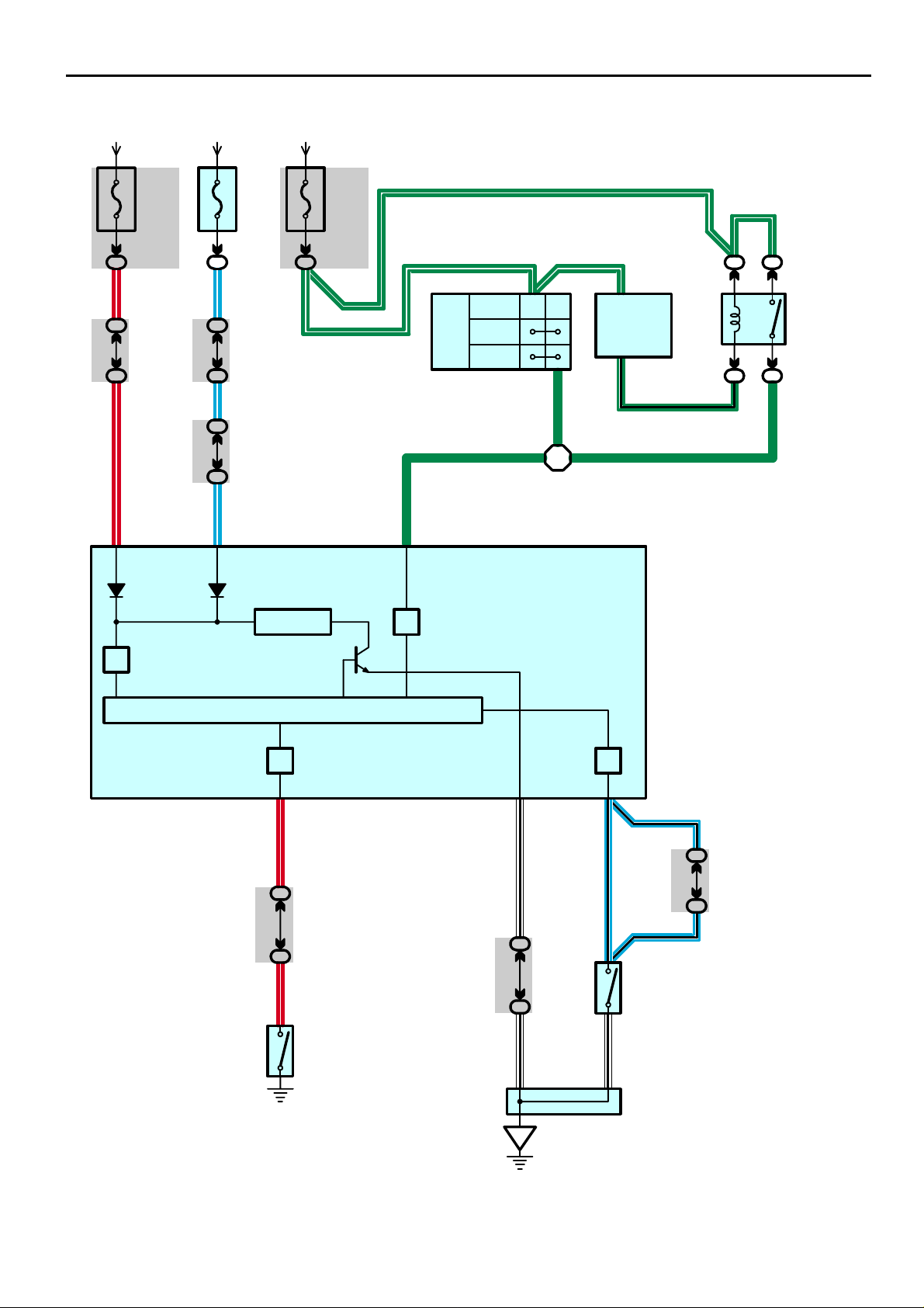
System Outline
The current is applied at all times to TERMINAL 5 of the combination meter through the DOME fuse.
When the ignition SW is turned to ON position, the current flows to TERMINAL 4 of the combination meter through the
GAUGE fuse. When the light control SW is turned to Tail or Head position, current is applied to TERMINAL 18 of the
combination meter through the TAIL fuse via the TAIL relay (USA) or the light control SW (Canada).
1. Light Reminder System
When the light control SW is in Tail or Head position, the ignition SW turned to OFF from ON position, and the driver’s door
opened (Door courtesy SW on), the current flows to TERMINAL 4 of the combination meter stops. As a result, the
combination meter is activated and current flows from TERMINAL 5 of the combination meter to TERMINAL 2 to GROUND,
the buzzer in the combination meter goes on to remind the light is lighting up.
2. Key Reminder System
When the driver door is opened with the ignition SW off and ignition key remaining in the key cylinder (Unlock warning SW
on), a signal is input from the unlock warning SW to TERMINAL 16 of the combination meter, and from the door courtesy SW
front LH to TERMINAL 17 of the combination meter. As a result, the buzzer in the combination meter goes on and warns the
driver that the key is remaining in the key cylinder.
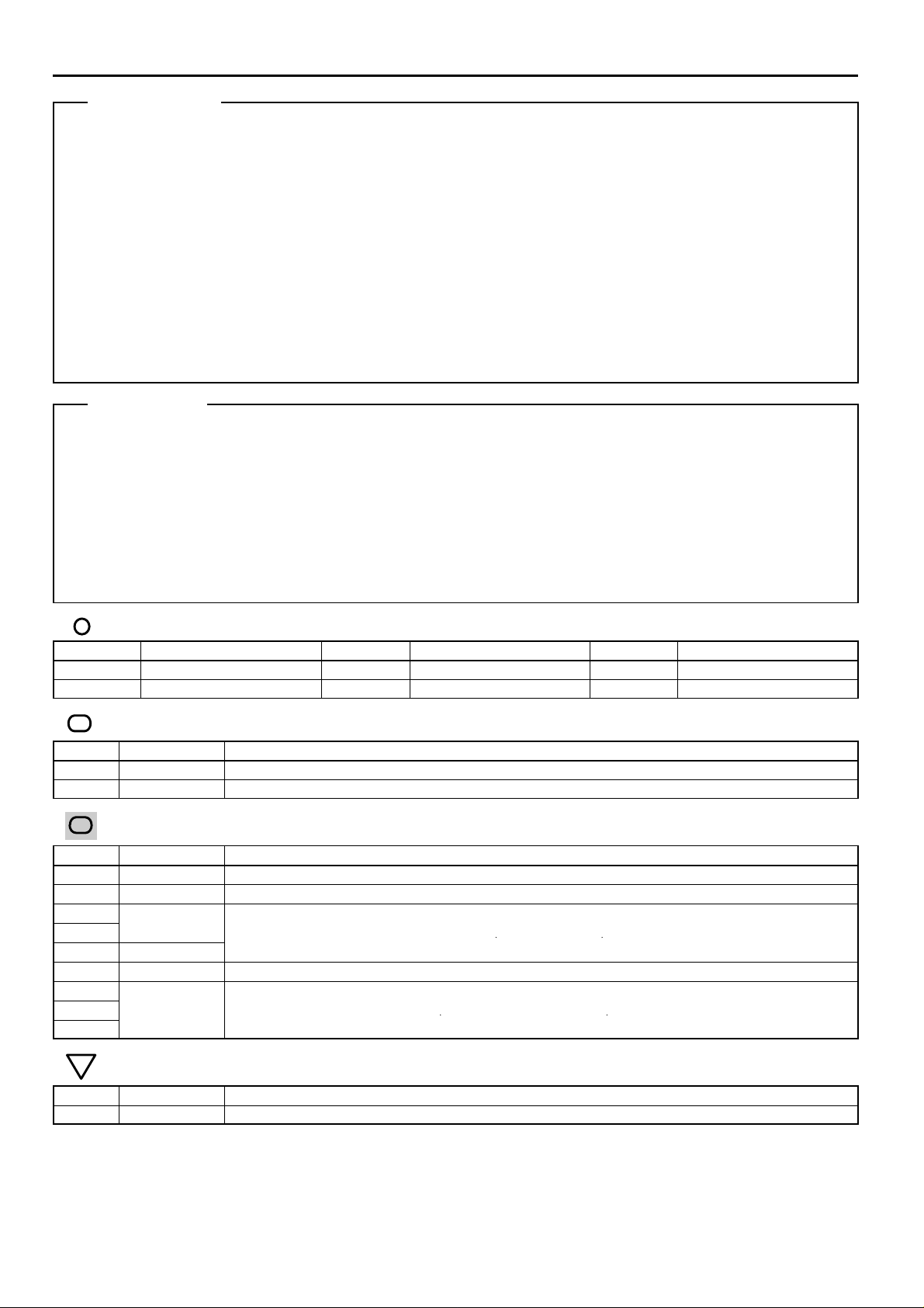
Service Hints
C9 Combination Meter
4–Ground : Approx. 12 volts with the ignition SW at ON position
18–Ground : Approx. 12 volts with the light control SW at Tail or Head position
17–Ground : Continuity with the driver’s door open
2–Ground : Always continuity
D4 Door Courtesy SW Front LH
1–Ground : Closed with the driver’s door open
U1 Unlock Warning SW
2–1 : Closed with the ignition key in cylinder
: Parts Location
Code See Page Code See Page Code See Page
C9 34 D2 34 J6 35
C12 34 D4 36 U1 35
:
Relay Blocks
Code See Page Relay Blocks (Relay Block Location)
1 22 Engine Room R/B (Engine Compartment Left)
3 28 RH R/B (Right Side of the Instrument Panel Reinforcement)
:
Junction Block and Wire Harness Connector
Code See Page Junction Block and Wire Harness (Connector Location)
IC 25 Engine Room Main Wire and Instrument Panel J/B (Lower Finish Panel)
ID 25 Floor Wire and Instrument Panel J/B (Lower Finish Panel)
IG
25
IH
IL 24
3B 28 Instrument Panel Wire and RH J/B (Right Side of the Instrument Panel Reinforcement)
4A
4B
4C
30 Instrument Panel Wire and Center J/B (Behind the Combination Meter)
:
Ground Points
Instrument Panel Wire and Instrument Panel J/B (Lower Finish Panel)
Code See Page Ground Points Location
IE 40 Behind the Combination Meter
169
2004 COROLLA (EWD533U)
 Loading...