

Page 1
W-603C
Videograbadoras
Contenido
Guía de servicio
Precauciones
Información de referencia
Especificaciones del producto
Desemsamble y reensamble
Ajuste y alineamiento
Vista explotada
Lista de partes de reemplazo
Diagrama a bloques
Diagramas PCB (Placa de Circuito Impreso)
Diagramas esquemáticos
Page 2

FILE NO. 120-200012
SERVICE MANUAL
VIDEO CASSETTE RECORDER
W-603C
PRINTED IN KOREA. APR, 2000
Page 3

TOTAL CONTENTS
◆ Service Guide
1. Precautions
2. Reference Information
3. Product Specifications
4. Disassembly and Reassembly
5. Alignment and Adjustment
6. Exploded View
7. Replacement Parts List
8. Block Diagram
9. PCB Diagrams
10. Schematic Diagrams
Page 4
Toshiba
I
SERVICE GUIDE
Assy Cylinder, the Capsrtan Motor & TM-Block are used for this model, as shown below.
Assy-Cylinder
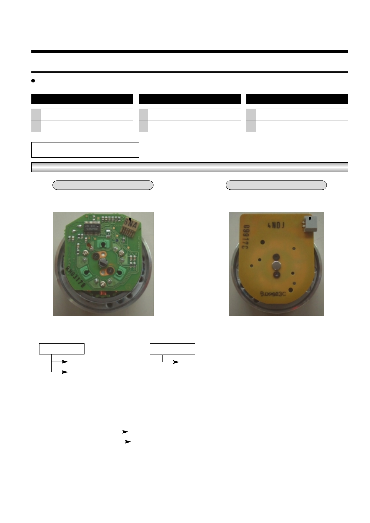
How to identify the Assy-Cylinder
Fig. 1
1) Three kinds of the Assy-Cylinder as shown below.
Œ ALPS Cylinder ´ SEM Cylinder
Connector ; Pin 7 Connector ; Pin 5
Connector ; Pin 5
2) When replacing the Assy-Cylinder, be sure to replace only “SEM Cylinder”.
The only part-no of “SEM Cylinder” is shown in the “CH7. Replacement Parts List” of Service Manual.
3) When changing from ALPS (connector ; pin 7) cylinder to SEM (connector ; pin 5) cylinder.
- Change CN605 (Connector ; pin 7 pin 5)
- Change CN605B (Cable-Flat ; pin 7 pin 5)
4) After replacing the “SEM Cylinder”, use type
“C, D, G, H”
optional for “NVRAM Option Setting”. (See page 5-9)
The Maker of Assy Cylinder
1
2
ALPS
SEM
The Maker of Assy Capstan Motor
1
2
SANKYO
SEM
Two kinds of TM-Block
1
2
SIF available
Not SIF availablea
ALPS Cylinder SEM Cylinder
CONNECTOR ; Pin 7 or Pin 5
CONNECTOR ; Pin 5
Page 5
II
Toshiba
How to identify the Capstan Motor
Fig. 2
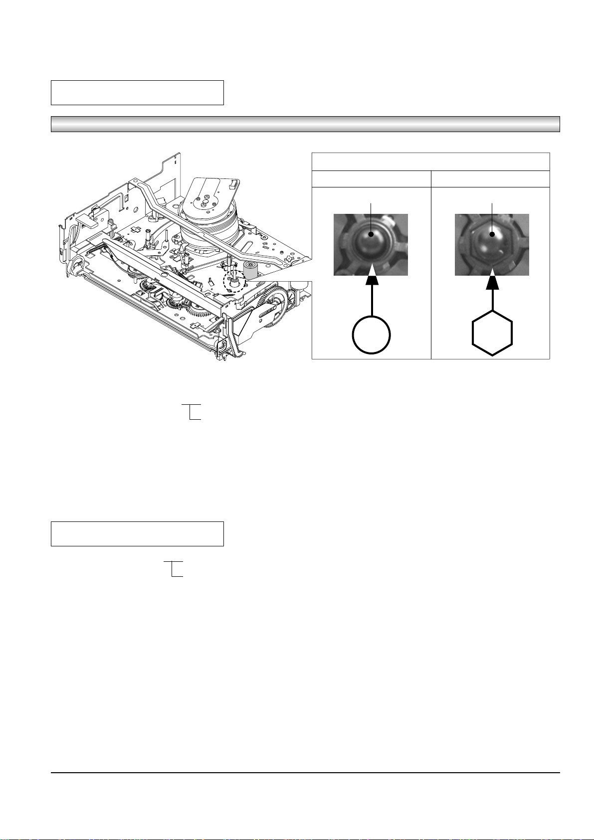
1) Two kinds of the Capstan Motor ΠSankyo Capstan Motor
´ SEM Capstan Motor
2) When replacing the Capstan Motor, be sure to replace only “SEM Capstan Motor”.
The only part-no of “SEM Capstan Motor” is shown in the “CH7. Replacement Parts List” of Service Manual.
3) After replacing the “SEM Capstan Motor”, use type
“E, F, G, H”
optional for “NVRAM Option Setting”. (See page 5-9)
Capstam Motor
TM-BLOCK
1) Two kinds of the TM-Blovk ΠSIF available
´ Not SIF available
2) How to identify TM-Block ; See page 5-11 (Fig. 5-21)
- In case there is VR501 ; Not SIF available
- In case there is no VR501 ; SIF available
3) When replacing the TM-Block as a service parts, be sure to replace only the TM-Block which is SIF available.
The only part-no of “SIF available” is shown in the “CH7. Replacement Parts List” of Service Manual.
4) After replacing “TM-Block”, use type
“B, D, F, H”
optional for “NVRAM Option Setting” regardless of VR501. (See page 5-9)
TOP VIEW
SANKYO CAPSTAN MOTOR SEM CAPSTAN MOTOR
CAPSTAN SHAFT CAPSTAN SHAFT
Page 6
Toshiba 1-1
1. Precautions
1. Be sure that all of the built-in protective devices are
replaced. Restore any missing protective shields.
2. When reinstalling the chassis and its assemblies, be
sure to restore all pretective devices, including :
control knobs and compartment covers.
3. Make sure that there are no cabinet openings
through which people--particularly children
--might insert fingers and contact dangerous
voltages. Such openings include the spacing
between the picture tube and the cabinet mask,
excessively wide cabinet ventilation slots, and
improperly fitted back covers.
If the measured resistance is less than 1.0 megohm
or greater than 5.2 megohms, an abnormality exists
that must be corrected before the unit is returned
to the customer.
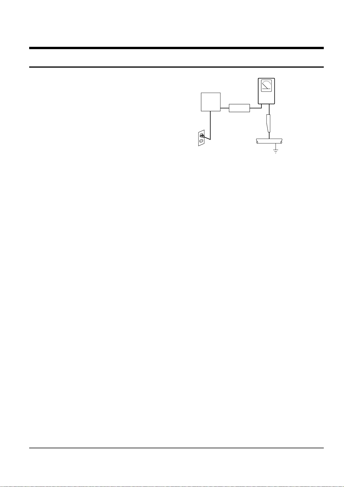
4. Leakage Current Hot Check (See Fig. 1-1) :
Warning : Do not use an isolation transformer
during this test. Use a leakage current tester or a
metering system that complies with American
National Standards Institute (ANSI C101.1,
Leakage Current for Appliances), and Underwriters
Laboratories (UL Publication UL1410, 59.7).
5. With the unit completely reassembled, plug the AC
line cord directly the power outlet. With the unit’s
AC switch first in the ON position and then OFF,
measure the current between a known erath
ground (metal water pipe, conduit, etc.) and all
exposed metal parts, including : antennas, handle
brackets, metal cabinets, screwheads and control
shafts. The current measured should not exceed
0.5 milliamp. Reverse the power-plug prongs in the
AC outlet and repeat the test.
6. X-ray Limits :
The picture tube is designed to prohibit X-ray
emissions. To ensure continued X-ray protection,
replace the picture tube only with one that is the
same type as the original.
Fig. 1-1 AC Leakage Test
7. Antenna Cold Check :
With the unit’s AC plug disconnected from the
AC source, connect an electrical jumper across the
two AC prongs. Connect one lead of the ohmmeter
to an AC prong.
Connect the other lead to the coaxial connector.
8. High Voltage Limit :
High voltage must be measured each time
servicing is done on the B+, horizontal deflection
or high voltage circuits.
Heed the high voltage limits. These include the
X-ray protection Specifications Label, and the
Product Safety and X-ray Warning Note on the
service data schematic.
9. Some semiconductor (“solid state”) devices are
easily damaged by static electricity.
Such components are called Electrostatically
Sensitive Devices (ESDs); examples include
integrated circuits and some field-effect transistors.
The following techniques will reduce the
occurrence of component damage caused by static
electricity.
10. Immediately before handling any semiconductor
components or assemblies, drain the electrostatic
charge from your body by touching a known
earth ground. Alternatively, wear a discharging
Wrist-strap device. (Be sure to remove it prior to
applying power--this is an electric shock
precaution.)
DEVICE
UNDER
TEST
(READING SHOULD
NOT BE ABOVE
0.5mA)
LEAKAGE
CURRENT
TESTER
EARTH
GROUND
TEST ALL
EXPOSED METER
SURFACES
ALSO TEST WITH
PLUG REVERSED
(USING AC ADAPTER
PLUG AS REQUIRED)
2-WIRE CORD
Page 7

Precautions
1-2 Toshiba
11. High voltage is maintained within specified limits
by close-tolerance, safety-related components and
adjustments. If the high voltage exceeds the
specified limits, check each of the special
components.
12. Design Alteration Warning :
Never alter or add to the mechanical or electrical
design of this unit. Example : Do not add
auxiliary audio or video connectors.
Such alterations might create a safety hazard.
Also, any design changes or additions will void
the manufacturer’s warranty.
13. Hot Chassis Warning :
Some TV receiver chassis are electrically
connected directly to one conductor of the AC
power cord. If an isolation transformer is not
used, these units may be safely serviced only if
the AC power plug is inserted so that the chassis
is connected to the ground side of the AC source.
To confirm that the AC power plug is inserted
correctly, do the following : Using an AC
voltmeter, measure the voltage between the
chassis and a known earth ground. If the reading
is greater than 1.0V, remove the AC power plug,
reverse its polarity and reinsert. Re-measure the
voltage between the chassis and ground.
14. Some TV chassis are designed to operate with 85
volts AC between chassis and ground, regardless
of the AC plug polarity. These units can be safely
serviced only if an isolation transformer inserted
between the receiver and the power source.
15. Never defeat any of the B+ voltage interlocks.
Do not apply AC power to the unit (or any of its
assemblies) unless all solid-state heat sinks are
correctly installed.
16. Always connect a test instrument’s ground lead to
the instrument chassis ground before connecting
the positive lead; always remove the instrument’s
ground lead last.
17. Observe the original lead dress, especially near
the following areas : Antenna wiring, sharp
edges, and especially the AC and high voltage
power supplies. Always inspect for pinched, outof-place, or frayed wiring. Do not change the
spacing between components and the printed
circuit board. Check the AC power cord for
damage. Make sure that leads and components
do not touch thermally hot parts.
18. Picture Tube Implosion Warning :
The picture tube in this receiver employs
“integral implosion” protection. To ensure
continued implosion protection, make sure that
the replacement picture tube is the same as the
original.
19. Do not remove, install or handle the picture tube
without first putting on shatterproof goggles
equipped with side shields. Never handle the
picture tube by its neck. Some “in-line” picture
tubes are equipped with a permanently attached
deflection yoke; do not try to remove such
“permanently attached” yokes from the picture
tube.
20. Product Safety Notice :
Some electrical and mechanical parts have special
safety-related characteristics which might not be
obvious from visual inspection. These safety
features and the protection they give might be
lost if the replacement component differs from the
original--even if the replacement is rated for
higher voltage, wattage, etc.
Components that are critical for safety are
indicated in the circuit diagram by shading,
( or ).
Use replacement components that have the same
ratings, especially for flame resistance and
dielectric strength specifications. Areplacement
part that does not have the same safety
characteristics as the original might create shock,
fire or other hazards.
Page 8
Toshiba 2-1
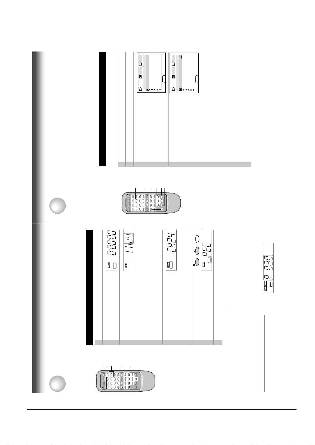
9
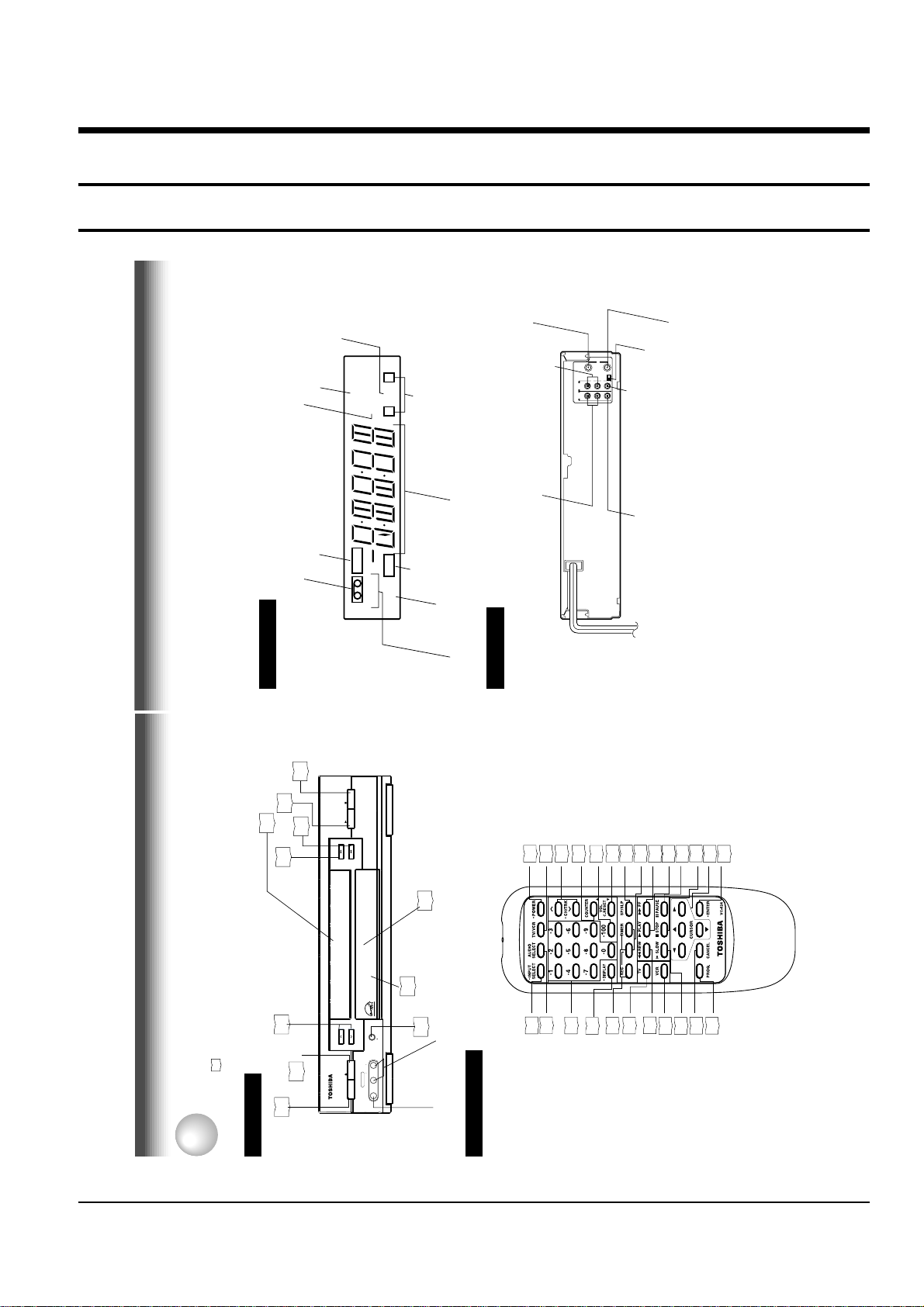
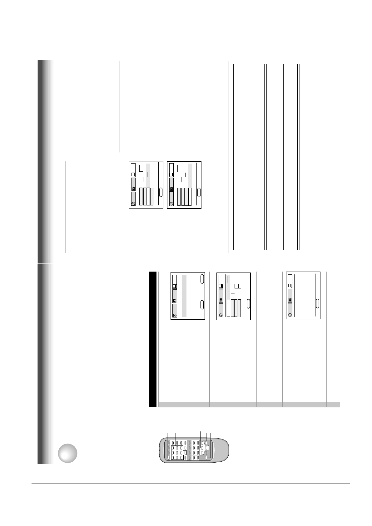
Rear Panel
LINE IN 1 AUDIO (Rear), 2 (Front) jacks
If the connected equipment is monaural (has one audio output jack), connect the L (MONO) side, the same
sound is recorded on both L and R on the Hi-Fi track.
Multifunctional
indicator
REC (Recording)
indicator
VCR indicator
Tape speed indicator (SP/SLP)
Cassette indicator
Timer recording indicator
STEREO indicator
Hi-Fi indicator
SAP indicator
Hi-Fi (L/R) indicators
L: Left channel
R:Right channel
off: Normal track
VCR Display
Hi-Fi
STEREO
SLP
SAP
VCR
REC
L R
TIMER
INTRODUCTION
L
R
CH selector (3/4)
LINE OUT AUDIO jacks (L, R)
LINE OUT VIDEO jack
RF IN (FROM ANT.) terminal
LINE IN 1 AUDIO jacks (L, R)
RF OUT (TO TV) terminal
LINE IN 1 VIDEO jack
CH
OUT
(
TO TV)
IN
(
FROM ANT.)
LINE
OUT
LINE
IN 1
VIDEO
AUDIO
34
RF
To wall outlet
2. Reference Information
2-1 Operation of Controls
STOP
19
PLAY
19
Cassete compartment
18
REW
19
FF
19
STOP
PLAY
FF
POWER
TV/VCR
CH/TRK
FF
REW
VCR Display
14
24
19
VOL/C.RESET
COUNTER
100
22
22
17
SP/SLP24TIMER
26
19
PLAY
19
PAUSE
20
STOP
CURSOR
19
14
ENTER
14
9
Remote
Sensor
Identification of Controls
INTRODUCTION
See the page in for details.
This manual shows the names of buttons in italics.
CHANNEL
24
EJECT
18
14
Front Panel
POWER
CHANNEL
EJECT
POWER
LINE IN 2
10
REC
L/MONO AUDIO R
VIDEO
REC
24
LINE IN 2 AUDIO
(L/MONO, R) jacks
LINE IN 2 VIDEO jack
Remote Control
24
22
24
24
28
REC
DISPLAY
INPUT SELECT
AUDIO SELECT
Number buttons
29
TV
19
REW
14
VCR
21
27
SLOW
CANCEL
14
PROG
8
Page 9
Reference Information
2-2 Toshiba
11
PREPARATION
VHF UHF
VHF/UHF
L
R
CH
OUT
(
TO TV)
IN
(
FROM ANT.)
LINE
OUT
LINE
IN 1
VIDEO
AUDIO
34
RF
OUT
(
TO TV)
IN
(
FROM ANT.)
RF
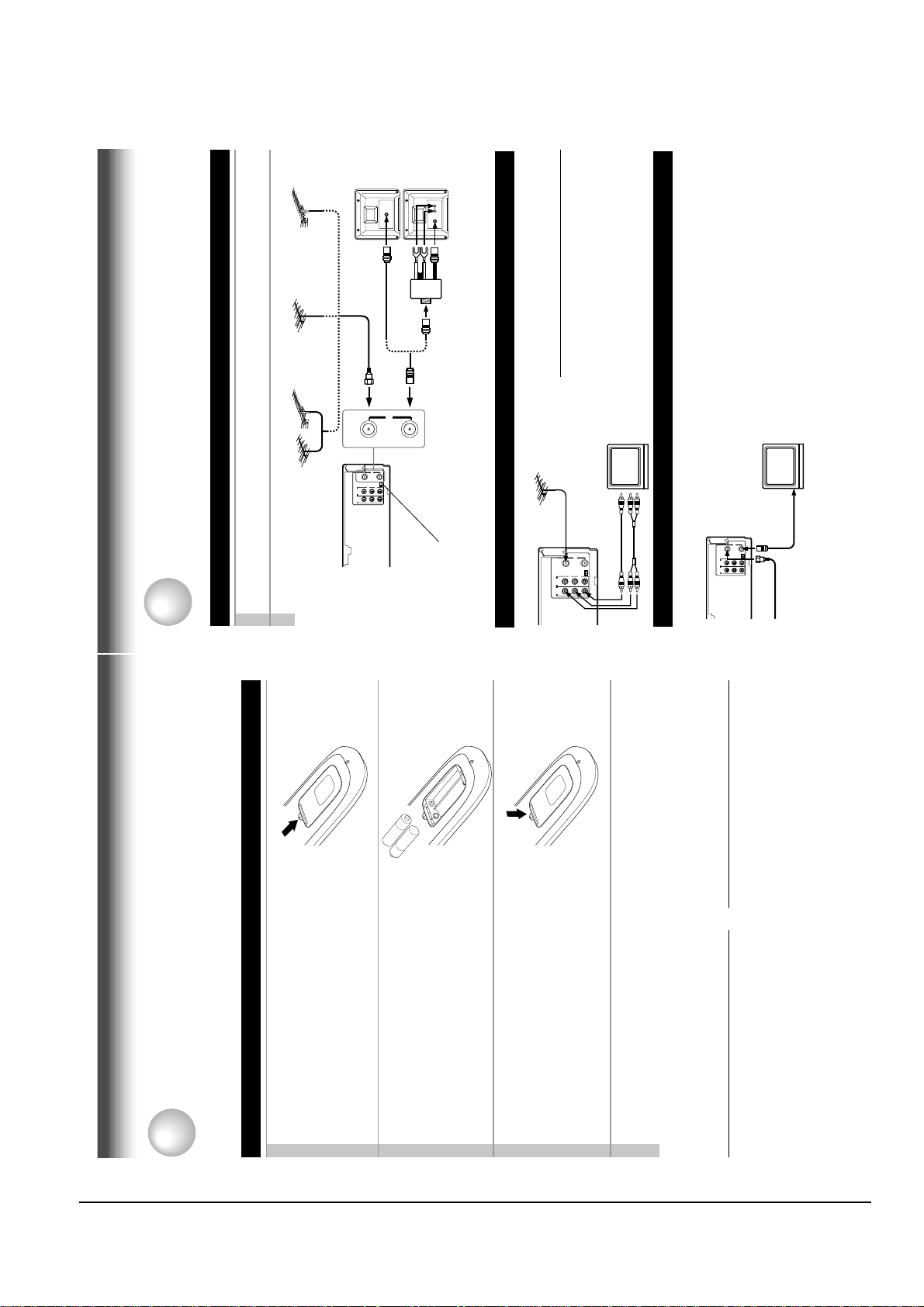
Antenna/VCR/TV Connection
1
Disconnect the antenna cable from your TV and connect it to the RF IN terminal on the
VCR.
2
Connect the RF OUT terminal to the TV.
AUDIO/VIDEO Connections
The AUDIO/VIDEO jacks are also available to connect your TV.
When connected your TV using the
AUDIO/VIDEO OUT jacks
To watch video pictures, set the video input mode
on your TV. For the video input mode, refer to
the manual of your TV.
Setting the VCR Output Channel
When the VCR is connected in this way, the VCR sends the output
signals to channel 3 or 4 on your TV. Set the output channel
selector (CH selector) of the VCR to “3” or “4”, whichever is vacant
in your area.
VHF/UHF
combinaion antenna
VHF antenna
only
UHF antenna
only
Antenna splitter
(not supplied)
1
2
Connections
Before you use this VCR, it is necessary to connect it to your TV. Several ways of connecting are
available depending on your use of TV or cable box. Select one which is applicable to your equipment.
PREPARATION
L
R
CH
OUT
(
TO TV)
IN
(
FROM ANT.)
LINE
OUT
LINE
IN 1
VIDEO
AUDIO
34
RF
LINE OUT VIDEO
VIDEO IN
AUDIO INLINE OUT AUDIO
Cable Connection
Choose one of the below according to your usage of the cable box.
This set-up will enable you to:
– record an unscrambled channel.
– watch an unscrambled channel while recording it.
– record an unscrambled channel while watching
another (only when you connect a cable-
compatible TV).
You will need to:
• select TV channel 3 or 4 to receive video signals.
• to record a channel while watching another, press
TV/VCR on the remote control to turn off the
“VCR” indicator in the VCR display and select a
desired channel on the TV (only when you connect
a cable-compatible TV).
L
R
CH
OUT
(
TO TV)
IN
(
FROM ANT.)
LINE
OUT
LINE
IN 1
VIDEO
AUDIO
34
RF
Incoming cable
+
+
This section explains how to get ready for remote control operation.
How to Use the Remote Control
PREPARATION
Open the battery compartment lid on the
rear panel.
Setting up the Remote Control
1
Install 2 batteries (“AA” size) following
2
the polarity diagrams.3Close the battery compartment lid.
Point the remote control at the VCR and press the buttons within the operating range.
Distance: within about 7 m from the front of the remote sensor
Angles: within about 30˚ in every direction
4
to a strong light source such as direct sunlight
or illumination (especially high-frequency
Caring for the remote control
Notes on batteries
lighting) when using the remote control.
• Do not expose the remote sensor of the VCR
depending on the conditions of use.
correctly, replace all batteries with new ones.
• The life of the batteries is about 1 year
• If the remote control does not operate
control or to place it on anything wet, and avoid
sharp impacts.
• Be careful not to spill water on the remote
long period of time, remove the batteries to
avoid possible damage from battery corrosion.
• If the remote control is not to be used for a
10
Page 10
Reference Information
Toshiba 2-3
13
PREPARATION
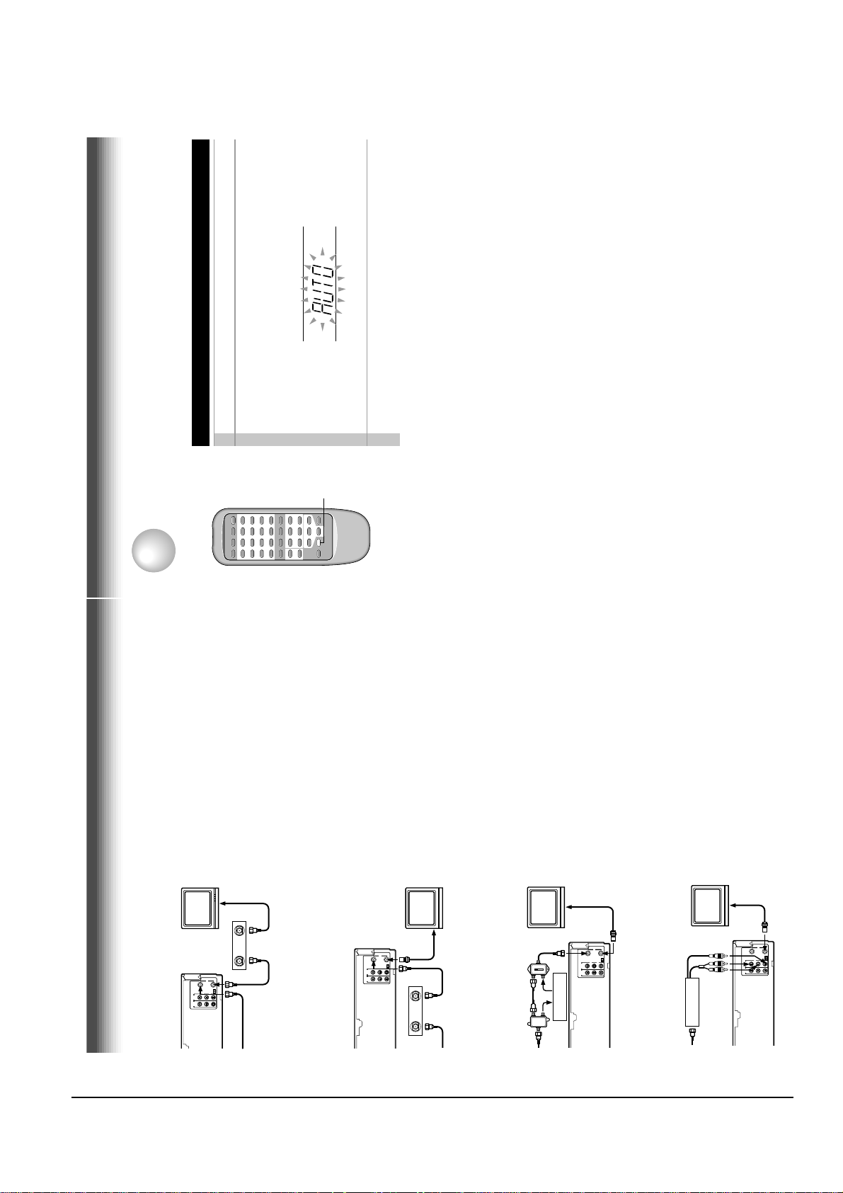
Auto Set Up
The VCR’s clock and tuner channels are set automatically when the VCR is plugged into the AC outlet.
PREPARATION
Auto Set up
1
Plug the VCR into the AC outlet2“AUTO” blink while the VCR automatically sets the clock
using the data broadcast by the local TV stations.
While “AUTO” is blinking, channel memory is also set
automatically.
3
When Auto set up has been completed, the VCR is on
standby mode.
Notes
• It may takes several minutes during the Auto set up
• Press CANCEL on the remote control to cancel the auto set up.
CANCEL
unscrambled channel which
comes bypassing the cable
box.
or unscrambled channel coming
through the cable box.
another (scrambled or unscrambled).
box.
or 4 according to the output channel of the VCR.
press TV/VCR on the remote control to turn off
the “VCR” indicator in the VCR display and select
This set-up will enable you to:
– record an unscrambled channel.
– watch an unscrambled channel while recording it.
– record an unscrambled channel while watching
You will need to:
• set TV channel to the output channel of the cable
• turn on the cable box and select cable channel 3
a desired cable channel on the cable box.
• to record a channel while watching another,
while recording it.
This set-up will enable you to:
– watch an unscrambled or scrambled channel
– record any channels through the cable box.
(See page 11.)
cable box, and select a desired cable channel
on the cable box.
indicator is not lit in the VCR display, set TV
You will need to:
• set TV channel 3 or 4 to receive video signals.
• set VCR channel to the output channel of the
channel to the output channel of the cable box.
• while the VCR is turned off or the “VCR”
while recording it.
This set-up will enable you to:
– watch an unscrambled or scrambled channel
another unscrambled channel (only when you
connect a cable-compatible TV).
– record an unscrambled channel while watching
• A/B switch “A”:record and watch an
• A/B switch “B”:record and watch a scrambled
box via the LINE IN 1 (AUDIO/VIDEO) jacks.
This set-up will enable you to:
– watch or record a channel through the cable
You will need to:
shows “L1”.
• press INPUT SELECT so that the VCR display
OUT
RF
IN
TO TV)
OUT
(
FROM ANT.)
(
CH
34
L
R
VIDEO
AUDIO
IN 1
LINE
OUT
LINE
Cable box
CH
34
IN
Incoming cable
RF
IN
TO TV)
OUT
(
FROM ANT.)
(
L
R
VIDEO
AUDIO
IN 1
LINE
OUT
LINE
Connections (continued)
RF
IN
TO TV)
OUT
(
FROM ANT.)
(
CH
34
L
R
VIDEO
AUDIO
IN 1
LINE
OUT
LINE
OUT
Cable box
IN
Incoming cable
A/B switch
A
A
B
A
B
B
Cable box
RF
IN
TO TV)
OUT
(
FROM ANT.)
(
CH
34
L
R
VIDEO
AUDIO
IN 1
LINE
OUT
LINE
Cable box
12
Page 11
Reference Information
2-4 Toshiba
15
PREPARATION
8
Press ENTER to start the “AUTO” clock
set feature.
After the VCR is turned off, it automatically
updates the clock using the data broadcast
by the local TV stations.
9
Select the options using CURSOR
( ) or ( ). Change the data using
CURSOR (▲) or (▼).
1) Set “SUMMER TIME
(Daylight-Saving Time)”.
DST start: Daylight-saving time begins on
the first Sunday in April. Because the
clock automatically changes from 2:00 AM
to 3:00 AM (forward one hour).
DST end: Daylight-saving time ends on
the last Sunday in October. The VCR
clock automatically changes from 2:00 AM
to 1:00 AM (back one hour).
remember that any part of a scheduled
Timer Recording that falls between these
two times will not be recorded.
AUTO: the VCR is using the clock data
Broadcast by the local TV stations.
IN: You want to use the DST function, and
you are leaving in the area that apply
Daylight-saving time.
OUT: You are not leaving in the area that
apply Daylight-saving time and you do not
want to use DST function.
2) Set “TIME ZONE”.
If you select “AUTO” for your time zone,
the VCR sets the clock using the first
Coordinated Universal Time information it
finds. If the time is not correct, select
another time zone or use the “MANU”
option.
3) Set “CLOCK DATA CH”.
If you don't know the clock data channel,
select “AUTO”. The VCR will scan
automatically to tune the channel carrying
the clock data.
If AUTO CLOCK SET is unsuccessful, set the
time and date through the “MANU” clock
set menu selection.
10
Press PROG..
Now the clock starts.
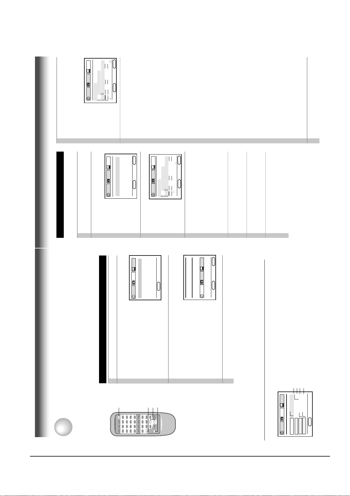
Setting the Clock
Example: To set the clock to 2:30 p.m. on
August 25 (summer time) 2000.
1
Press PROG..
The MENU screen appears on the TV.
2
Select “PRESET” using CURSOR ( ) or
( ), and press ENTER.
3
Press ENTER to select “CLOCK SET”.
4
Select “AUTO” or “MANU” using
CURSOR (▲) or (▼).
AUTO: The VCR automatically sets or
adjusts the clock.
If you select “AUTO” mode, proceed to step 8.
MANU: You can set the clock manually.
If you select “MANU” mode, proceed to next
step.
5
Vary the digits to set the hour.
CURSOR ▲: To increase.
CURSOR ▼ : To decrease.
6
Move to the next using CURSOR ( )
(To move back, press CURSOR ( ).)
7
Repeat step 5 and 6 to set the minutes,
month, day, and the year (by the last
two digits).
Proceed to step 10 to start the clock.
E
n
D : PROG
SET UP
PRESET
PROGRAM
ENTER
CLOCK SET
CH MEMORY
▼
▼
▼
▼
▼
▼
E
n
D : PROG
SET UP
PRESET
PROGRAM
ENTER
CLOCK SET
SUMMER TIME
TIME ZO
n
E CH
AUTO
AUTO
AUTO
PRESS E
n
TER
TO START SETTI
n
G
E
n
D : PROG
SET UP
PRESET
PROGRAM
ENTER
CLOCK SET
SUMMER TIME
TIME ZO
n
E CH
AUTO
AUTO
AUTO
AUTO
2
SCA
nn
I
n
G
n
O
W
* The clock is
revised by
broadcasting
signal at 8:00 A.M
every morning.
The language selection and clock setting must be set first when VCR is first plugged in or after it
encounters a power failure.
Initial Settings Using On-screen Display
PREPARATION
Preparation
ENTER
U
n
ME
PRESET
SET UP
PROGRAM
D : PROG
n
E
PRESET
SET UP
PROGRAM
English
Français
Español
D : PROG
n
E
1
2
Press POWER to turn on the VCR.
Press PROG..
The following screen appears on the TV.
Setting the Language
The screen turns to the MENU screen.
3
Press PROG. to return to the normal TV screen.
4
Select the language using CURSOR
(▲) or (▼) , and press PROG..
POWER
connection (page 11).
• Turn on the TV, and select the video channel (3 or 4), or the video input mode if you made the Audio/Video
• Press VCR to set the remote control operating the VCR.
CURSOR
VCR
PROG
Page 22
Page 28
To change the language, move down here and set to the desired one.
PRESET
SET UP
PROGRAM
Optional settings on the SET UP screen
Other optional settings can be made. Press ENTER while “SET UP” is selected on the MENU screen.
The screen turns to the SET UP screen.
Page 23
G FRA ESP
n
on off
120 160 180
GTH
on off
n
TER MEM
GUAGE E
n
D : PROG
n
n
LA
SAP SET
TAPE LE
COU
E
To exit, press PROG. twice.
14
Page 12
Reference Information
Toshiba 2-5
17
PREPARATION
To add channels
To erase channels
Channel reference chart
Number on the VCR
Corresponding channel number
TV
CATV STD (HRC/IRC)
CH NUMBER 1 2 3 4 5 6789
– 23456789
1(A-8)
234
5(A-7) 6(A-6)
7
89
10 11 12 13 14 15 16 17 18 19 20 21 22 23 24 25 26 27 28 29 30
10 11 12 13 14 15 16 17 18 19 20 21 22 23 24 25 26 27 28 29 30
10 11 12 13 A B C D E F G H I J K L M N O P Q
31 32 33 34 35 36 37 38 39 40 41 42 43 44 45 46 47 48 49 50 51
31 32 33 34 35 36 37 38 39 40 41 42 43 44 45 46 47 48 49 50 51
R S T U V W AA BB CC DD EE FF GG HH II JJ KK LL MM NN OO
52 53 54 55 56 57 58 59 60 61 62 63 64 65 66 67 68 69 70 71…52 53 54 55 56 57 58 59 60 61 62 63 64 65 66 67 68 69 ––
…
PP QQ RR SS TT UU VV WW XX YY ZZ AAA BBB 65 66 67 68 69 70 71
…
93 94 95 96 97 98 99 100 101 102 103
…
121 122 123 124 125
–––––––––––
…
–––––
93 94 A-5 A-4 A-3 A-2 A-1 100 101 102 103
…
121 122 123 124 125
3)Enter a channel number of 1 to 125 using
number buttons.
For more than 100 number, first press 100.
For CATV channels, refer to the chart below.
(For other orders, check with your cable
company.)
4)Repeat steps 2) and 3) to add or erase
channels as necessary.
5)Press PROG. three times to exit.
Selecting stored channels
Once the active channels have been stored, you
can select the channels in two ways below.
Number buttons
To enter digits of the channel number.
• For one-digit number, enter 0 before.
• For more than 100 number, first press 100.
• Each number button needs to be pressed
within 2 seconds.
CH/TRK buttons
To shift up or down the stored channel numbers.
CATV signals
• STD (standard) cable TV signals
• HRC (Harmonic Related Carriers) cable TV signals
• IRC (Incremental Related Carriers) cable TV signals
IRC is also called ICC (Incremental Coherent Carriers)
Adding or erasing channels
Adding channels
If a desired channel cannot be scanned
automatically because of a weak signal, it can be
added to the memory.
Erasing channels
You can erase a stored channel from the memory
if it is unnecessary.
1)Follow steps 1 to 3 of “Incoming Antenna/
CATV Signals”.
2)Select “ADD CH” or “ERASE CH” using
CURSOR (▲) or (▼).
E
n
D : PROG
SET UP
PRESET
PROGRAM
TV/CATV TV CATV
AUTO SCA
n
OFF O
n
ADD CH - - CH
ERASE CH - - CH
TO SET CH PUSH 0~9 KEYS
E n D : PROG
SET UP
PRESET
PROGRAM
TV/CATV TV CATV
AUTO SCA
n
OFF O
n
ADD CH - - CH
ERASE CH - - CH
TO SET CH PUSH 0~9 KEYS
Storing Channels on the VCR
PREPARATION
This section is required if you receive only normal TV or unscrambled cable channels, or use a cable box
between your TV and the VCR.
PRESET
SET UP
CLOCK SET
CH MEMORY
PROGRAM
▼
▼
Press PROG. to display the MENU screen.
Select “PRESET” using CURSOR
1
INPUT
( ) or ( ), and press ENTER.
2
SELECT
Number
buttons
100
Incoming Antenna/Cable(CATV) Signals
The VCR scans through all receivable TV and CATV channels and stores only the active
ones in your area into the memory. Once the storing is finished, you can select a desired
channel using CH/TRK.
Preparation
• Turn on the TV, and select the video channel (3 or 4), or the video input mode if you made the Audio/Video
connection (page 11).
• Press INPUT SELECT so that the channel number will appear if “L1” or “L2” is displayed in the VCR display.
Incoming Antenna/Cable(CATV) Signals
PRESET
ENTER
SET UP
D : PROG
n
E
CURSOR
PROGRAM
TV/CATV TV CATV
Select “CH MEMORY” using
CURSOR (▲) or (▼), and press
ENTER
ENTER.
3
1, 6
n
▼
OFF O
n
D : PROG
n
ADD CH - - CH
AUTO SCA
ERASE CH - - CH
E
PRESET
SET UP
2 CH on
n
PROGRAM
AUTO SCA
D : PROG
n
E
▼
▼
( ).
Set “TV/CATV“ to “TV” or “CATV” using CURSOR ( ) or
TV: To store channels received via the antenna.
CATV: To store channels received via the incoming cable.
Select “AUTO SCAN” using
CURSOR (▲) or (▼), and press
The VCR starts scanning and the
channels are stored in the VCR in
ascending order. When the scanning is
finished, the screen automatically
4
CURSOR ( ) to set to “ON”.
5
returns.
Press PROG. three times to exit.
6
16
Page 13
Reference Information
2-6 Toshiba
19
PLAYBACK
Adjusting the tracking
When playback starts, the VCR automatically adjusts the tracking for clear pictures and sound
(Digital Auto Tracking).
If the VCR cannot locate the best possible tracking point, hold down one of CH/TRK to adjust the
tracking manually.
Notes
• During the adjusting, the playback picture and sound may be distorted.
• The digital auto tracking is activated only in the playback mode.
• The noise on the screen may not be completely eliminated depending on the tape used, especially when the
tape was recorded on another VCR.
Basic Playback
1
Load a recorded cassette.
Power is turned on.
If the cassette has no safety tab,
playback starts automatically.
2
Press PLAY to start playback.
3
T o stop playback, press STOP.
To resume normal playback
Press PLAY again
Rewinding / Fast-forwarding
Press REW or FF in the stop mode.
PLAYBACK
Playback
This section explains the basic playback operation.
Preparation
• Select the video channel (3 or 4) or video input mode on the TV.
• Press VCR to set the remote control operating the VCR.
REW
CH/TRK
FF
3
2
1
Press PLAY during playback.
A tape runs at double speed
playback.
Double Speed Playback
TIMER
S
SLP
S
L
REC
TIMER
VCR
S L P
S
TIMER
L
REC
S L P
VCR
L
REC
VCR
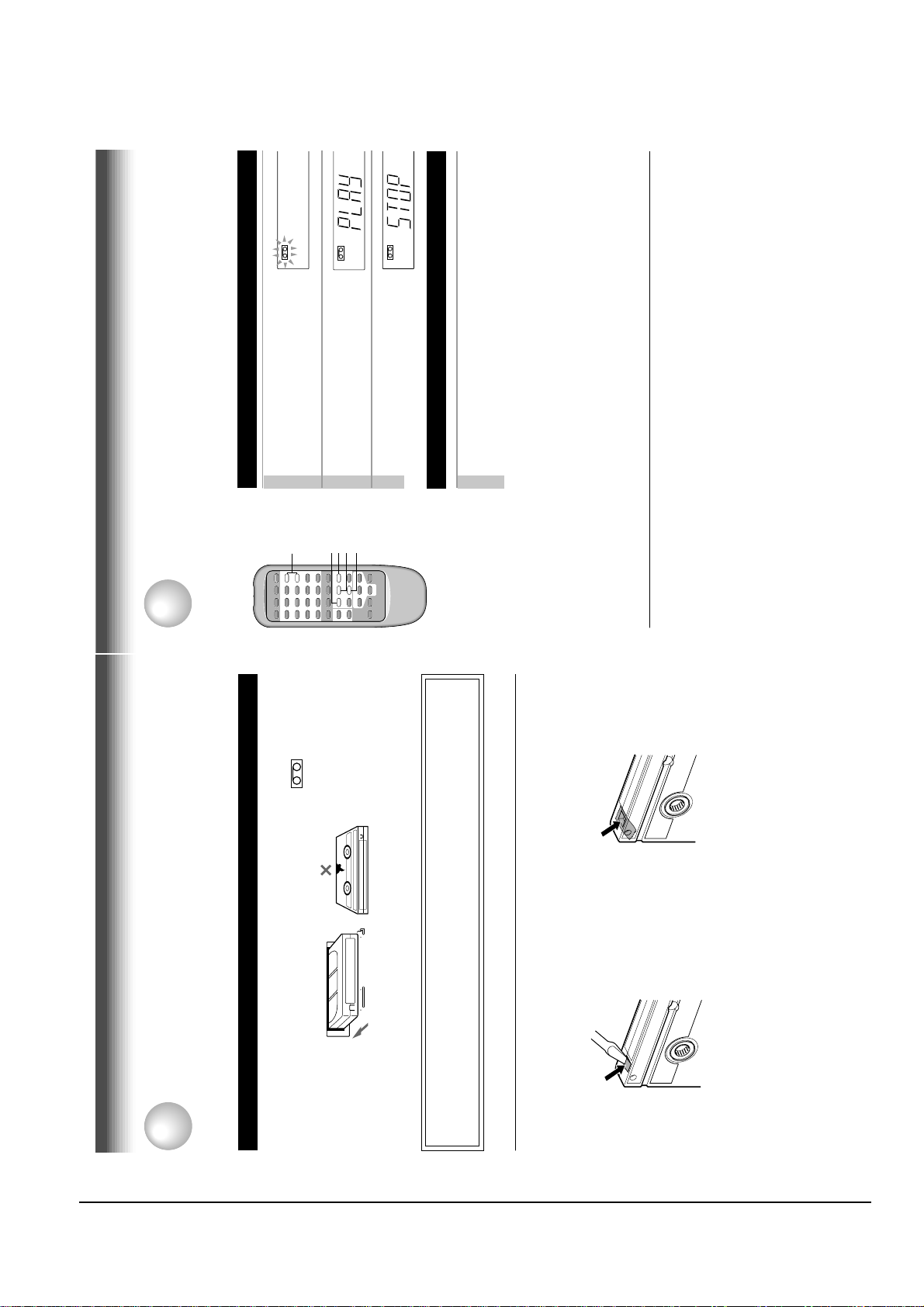
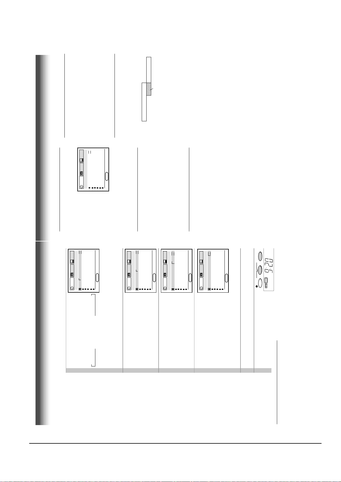
Video Cassette Use
PREPARATION
Video Cassette Use
To record again
Cover the tab hole with adhesive tape.
Loading a cassette
Push the cassette into the cassette compartment with the window side facing up and the
label side towards the front. The VCR is automatically turned on. The indicator will
appear in the VCR display.
Warning
Do not insert your hands or any foreign objects into the compartment. This may result
Ejecting a cassette
Press EJECT. The cassette is ejected from the cassette compartment.
in injury or damage. Take special care with children to avoid accidents.
Precautions when using video cassettes
Video cassettes have a safety tab to prevent accidental erasure. If the tab has already been removed,
recording cannot be performed.
To prevent accidental erasure
Remove this safety tab with a screwdriver.
Avoid extreme humidity, vibrations or shock, strong magnetic fields (near a motor, transformer or
magnet) and dusty place.
• Avoid exposing cassettes to direct sunlight. Keep them away from heaters.
18
Page 14
Reference Information
Toshiba 2-7
21
PLAYBACK
Frame Advance
A picture advances frame by frame.
1
Press PLAY during still playback.
Each time you press PLAY, the picture advances one frame.
Slow-motion Picture
The tape runs at 1/7th or 1/15th the normal playback speed.
1
Press SLOW during playback.
The tape runs at about 1/7th the normal playback speed.
Each time you press SLOW, the speed alternates between 1/7th and
1/15th.
To resume normal playback
Press PLAY.
Notes
• The slow-motion picture mode is automatically cancelled after about 5
minutes and returns to normal playback.
• The slow-motion picture may flicker up and down. This is not a defect in the
unit.
Adjusting the Tracking Manually
If the slow-motion picture is noisy, hold down one of CH/TRK until the
best picture is obtained.
Note
The noise in the slow-motion picture may not be eliminated completely.
To resume normal playback
Press PAUSE.
Picture Search
PLAYBACK
You can play back a tape at various tape speeds.
Variable Speed Playback
Press FF or REW during playback.
A tape runs at 5 times or 7 times the normal playback speed so
that you can quickly locate a particular scene.
1
The tape runs at 5 times the normal playback speed.
To change the tape speed to 7 times the normal playback
speed, press and hold FF or REW.
If you release it, the tape speed returns to 5 times.
2
Note
If you press FF or REW during picture search, the mode changes to fast-
forwarding or rewinding.
To resume normal playback
Press PLAY.
FF
PLAY
REW
PAUSE
SLOW
Press PAUSE during playback.
Still Picture
The picture freezes.
A picture freezes so that you can watch closer.
1
To resume normal playback
Press PAUSE again.
Notes
• The still mode is automatically cancelled after about 5 minutes and returns to
normal playback.
frozen. This is not a defect in the unit.
• The still picture may shake if a picture of a fast-moving object or scene is
Adjusting Still Picture Stability
If the still picture is distorted or flickers, hold down one of CH/TRK until
the picture becomes stable.
Note
The distortion of the still picture may not be eliminated completely.
20
Page 15
Reference Information
2-8 Toshiba
23
PLAYBACK
1
On the SET UP screen, select
“COUNTER MEM.” using CURSOR
(
▲
) or (
▼
), and set to “ON” using
CURSOR ( ) or ( ).
2
Press PROG. twice to exit.
The memory-stop feature allows you to quickly return to a
counter reading of “0H00M00S” from any point on the tape.
Memory stop is automatically turned on whenever the time
counter with memory is displayed on the TV screen. This is
convenient when you want to watch a segment of the tape
repeatedly. You may also discover other useful application for
this feature.
Notes: If you are rewinding the tape and the VCR stops at
“0H00M00S M”, press REW again to continue
rewinding.
If you press the FF (fast-forward) button and the time
counter never reaches “0H00M00S M” between that
point and the end of the tape, the VCR will continue to
fastforward to the end of the tape.
Memory Stop Feature (Zero Return)
▼
▼
COUNTER
CURSOR
C.RESET
DISPLA Y
ENTER
PROG
E
n
D : PROG
SET UP
PRESET
PROGRAM
TAPE LE
n
GTH
120 160 180
COU
n
TER MEM
on off
LA
n
GUAGE E
n
G FRA ESP
SAP SET
on off
PLAYBACK
These functions will help your playback.
Useful Functions in Tape Operation
Counter Function
You can view the clock, linear time counter or tape remaining
time in the VCR display or on the TV screen.
→ Linear time counter → Tape remaining time (RT) → Clock
Each time you press COUNTER, the VCR display changes in
sequence as follows:
COUNTER
The indication above will also appear on the TV screen by pressing
DISPLAY. They are switchable with COUNTER.
To reset the linear time counter to “0:00:00”
The counter is automatically reset to “0:00:00” when a cassette is
ejected. If you want to reset at another point, such as the beginning of a
new recording, just press C. RESET.
PROG
ENTER
CURSOR
C.RESET
DISPLA Y
clock.
Notes
• The linear time counter does not work on non-recorded portions on the tape.
• When the tape is ejected or the VCR is turned off, the display changes to
• If the tape rewinds back over “0:00:00”, “–” appears in the VCR display.
• The displayed time of the linear time counter is only an approximation.
▼
▼
Turn on the VCR and load a cassette.
Press PROG. to display the MENU screen.
Select “SET UP” using CURSOR ( ) or ( ), and press
Tape Remaining Time
To view the tape remaining time in the VCR display, select the
tape length beforehand.
1
ENTER.4Select the length of the tape, using
2
3
PRESET
SET UP
on off
120 160 180
GTH
on off
n
TER MEM
n
PROGRAM
SAP SET
TAPE LE
COU
▼
▼
CURSOR ( ) or ( ).
T120: for a T-120 tape or shorter
T160: for a T-140 or T-160 tape
T180: for a T-180 tape
G FRA ESP
n
GUAGE E
D : PROG
n
n
LA
E
Press PROG. twice to exit.
Press COUNTER.
The remaining time (“RT - : - -”) appears in the VCR display.
5
6
and the cassette type.
Notes
• The displayed remaining time is an approximation.
• The remaining time is calculated according to the tape speed (SP or SLP)
22
Page 16
Reference Information
Toshiba 2-9
25
RECORDING
Timer Programming Procedure
Example: To record cable channel 25 in the SP tape speed from
9:30 p.m. until 10:00 p.m. on August 30. Today is August 25.
1
Load a cassette with the safety tab attached.
2
Press PROG. to display the MENU screen.
3
Select “PROGRAM” using CURSOR
( ) or ( ), and press ENTER.
4
Move to the next using CURSOR
( ), and select the channel number
25 by pressing number buttons 2
and 5 or using CURSOR (
▲
) or (
▼
).
• To record a cable program from the connected cable box:
Enter the cable channel number using CURSOR (
▲
), (
▼
) or by
pressing number buttons.
If your cable box is not remote-controllable, choose the desired
channel (1 to 125) on the cable box.
To make corrections:
Press CURSOR ( ) to move back to the item, or CURSOR ( ) to
forward.
(Continued)
Timer Program Recording
The programmable timer allows you to record up to 6 different programs over one month.
Preparation
• Select the video channel (3 or 4) or video input mode on the TV.
• Make sure that the clock is set correctly (page 15).
• Store the channels on the VCR (pages 16 and 17).
• If you record cable channels, finish the cable box set-up (pages 12), and turn on the cable box.
RECORDING
E
n
D : PROG
SET UP
PRESET
PROGRAM
CH DATE O
n
OFF SPD
- - -/-- -:- - -:- - -
- - -/-- -:- - -:- - -
- - -/-- -:- - -:- - -
- - -/-- -:- - -:- - -
- - -/-- -:- - -:- - -
- - -/-- -:- - -:- - -
E
n
D : PROG
SET UP
PRESET
PROGRAM
CH DATE O
n
OFF SPD
- - -/-- -:- - -:- - -
- - -/-- -:- - -:- - -
- - -/-- -:- - -:- - -
- - -/-- -:- - -:- - -
- - -/-- -:- - -:- - -
2 5 -/-- -:- - -:- - SLP
▼
▼
▼
▼
▼
CANCEL
3
2,9
10
4
CURSOR
TIMER
REC
S L P
Basic Recording
This section explains the basic recording operation.
Recording a TV Program
RECORDING
Preparation
• Select the video channel (3 or 4) or video input mode on the TV.
box.
• If you record cable channels via the cable box, finish the cable box set-up (pages 12), and turn on the cable
VCR
Load a cassette with the safety tab attached.
Press TV/VCR so that the “VCR”
indicator appears in the VCR display.
1
2
3
INPUT
SELECT
2
S
H
ST
L
TIMER
REC
S L P
VCR
Select a channel to record with
CHANNEL on the VCR, or CH/TRK
If you see “L1” or “L2” in the VCR display, press INPUT SELECT so
or number buttons on the remote
control.
channel number of the cable box or “L1” appear, depending on your
connection. (See pages 11 – 12.)
that the channel number appears.
• If you record cable channels via the cable box, make the output
3
4
6
5
TIMERREC
TIMER
S
L
REC
S L P
VCR
TIMER
S
L
REC
S L P
VCR
Press SP/SLP to select the
recording tape speed.
SP: Suitable for general recording with
better picture and sound quality.
SLP: Suitable for tripling recording time, but with less picture and
sound quality than using the SP tape speed.
Press REC on the VCR, or
simultaneously press both REC on
4
5
the remote control.
Recording starts.
Recording off time setting
Press STOP to stop recording.
6
NPUT SELECT
To record from other
connected equipment
In step 3, press I
to switch the display as follows:
L1: To record via the LINE IN 1
jacks on the rear panel.
Watching a TV program while
L2: To record via the LINE IN 2
jacks on the front panel.
recording another
SAP
Hi-Fi
STEREO
L R
TIMER
By setting the recording off time, the recording
stops and the VCR is turned off automatically.
While recording, press simultaneously both REC
on the remote repeatedly to set the desired off
time.
Each time you press REC, each half-hour up to
“VCR” indicator.
selector on the TV.
1)While recording, press TV/VCR to turn off
2) Choose another channel using the channel
REC
S L P
VCR
about 4 hours appear cyclically.
Skipping unnecessary scenes while
recording
Press PAUSE to stop recording momentarily. To
resume recording, press PAUSE again.
Notes
• To cancel the recording in progress, press
Note
The VCR automatically shifts to the stop mode if the
POWER on the VCR.
recording pause mode continues for 10 minutes.
24
Page 17
Reference Information
2-10 Toshiba
27
RECORDING
If a power failure occurs during the
timer program recording
• When a power failure has occurred, “- -:- -”
appears in the VCR display. Since the
programmed contents have been cleared,
reset the clock and timer programming.
• When power has failed for a short time, the
colon of the current time display blinks. The
programmed contents are not affected. Reset
the clock.
Overlaps of the programs
If two timer programs overlap, the recording start
time of program 1 has priority over the recording
off time of program 2.
Program 1
(Start time)
Program 2
(Start time)
Overlapped portion
(not recorded)
Confirming the timer programs
Press PROG while timer recording.
The screen for confirming will appear.
This screen can be sure only in the Timer
Recording mode.
Changing/cancelling the timer
programs
1)If the TIMER indicator is lit, turn the VCR on by
pressing POWER.
2)With steps 2 to 9, change the items.
To cancel a program, select the program you
want to cancel in step 4, and press CANCEL.
The line is then cleared.
3)Press POWER to return to the timer standby
mode.
Error indication
The blinking “TIMER” indicator appears in the
VCR display if you press both TIMER when:
–– a cassette is not loaded.
–– the loaded cassette has no safety tab.
In these cases, a recording can not be made.
E n D : PROG
SET UP
PRESET
PROGRAM
CH DATE O
n
OFF SPD
- - -/-- -:- - -:- - -
- - -/-- -:- - -:- - -
- - -/-- -:- - -:- - -
- - -/-- -:- - -:- - -
- - -/-- -:- - -:- - -
2 5 8/30 9:30 10:00 SP
P
M
P
M
PRESET
OFF SPD
n
SET UP
CH DATE O
- - -/-- -:- - -:- - -
- - -/-- -:- - -:- - -
- - -/-- -:- - -:- - -
2 5 8/30 -:- - -:- - SLP
- - -/-- -:- - -:- - -
PROGRAM
- - -/-- -:- - -:- - -
E n D : PROG
…
SU →
).
WKLY
▼
SA ←
) or (
WKLY
▲
→ 7/25 →
…
▼
Move to the next using CURSOR
( ), and set the recording date
using CURSOR (
The date changes as follows:
MO~FR ←
→ 8/25 → 9/25 →
5
PRESET
M
P
OFF SPD
n
SET UP
CH DATE O
- - -/-- -:- - -:- - -
- - -/-- -:- - -:- - -
- - -/-- -:- - -:- - -
- - -/-- -:- - -:- - -
- - -/-- -:- - -:- - -
2 5 8/30 9:30 -:- - SLP
PROGRAM
[WKLYSA]: You can record TV programs on the same
…
D : PROG
n
E
▼
[WKLYSU]
channel on the day and time every week.
[MO~FR]: You can record TV programs on the same channel on the
day and time Monday through Friday.
Move to the next using CURSOR
( ), and set the hour and minutes
of the recording start time.
6
Move to the next, and set the
7
M
P
PRESET
M
P
OFF SPD
n
SET UP
CH DATE O
- - -/-- -:- - -:- - -
- - -/-- -:- - -:- - -
- - -/-- -:- - -:- - -
- - -/-- -:- - -:- - -
- - -/-- -:- - -:- - -
2 5 8/30 9:30 10:00 SLP
PROGRAM
recording off time.
M
P
PRESET
M
P
OFF SPD
n
SET UP
CH DATE O
- - -/-- -:- - -:- - -
- - -/-- -:- - -:- - -
- - -/-- -:- - -:- - -
- - -/-- -:- - -:- - -
- - -/-- -:- - -:- - -
2 5 8/30 9:30 10:00 SP
PROGRAM
E n D : PROG
).
▼
) or (
▲
Move to the next, and select the
tape speed (SP) using CURSOR
(
D : PROG
n
E
).
▼
▼
For the tape speed “AUTO (Auto Speed
Select)”, see below.
Repeat steps 4 to 8.
To set another program, press CURSOR
( ), and select the next line pressing
CURSOR (
8
SAP
Hi-Fi
STEREO
L
TIMERREC
TIMER
according to the tape used on the SET UP screen
(page 22).
Notes
• Make sure that the tape length is selected correctly
• When the SLP tape speed is selected and the tape
Press PROG..
Now programming is completed.
Press both TIMER simultaneously.
The power turns off and the VCR enters
the timer standby mode.
9
10
length is not sufficient to record the program to the
end, the program cannot be recorded to the end.
where the recording tape speed is switched from
SP to SLP with the Auto Speed Select feature.
• The picture will be distorted when playing the part
Auto Speed Select
If you are not sure the tape is long enough for
timer program recording in the SP tape speed,
set the recording tape speed to “AUTO”.
Recording starts in the SP tape speed and the
VCR automatically selects the tape speed to
Timer Program Recording (continued)
record the program to the end. If the tape length
is not long enough, the tape speed automatically
changes from SP to SLP.
26
Page 18
Reference Information
Toshiba 2-11
29
ADDITIONAL INFORMATION
Setting Control Codes
1
Press TV to set the remote control operating your TV.
2
3
Release TV.4Point the remote control at your TV and use each button
listed below to make sure that your TV is operated correctly.
POWER To turn the TV on or off.
CH/TRK To select TV channels in the upper or lower
direction.
VOL To adjust TV sound level.
INPUT SELECT To select an external source such as a VCR.
Number buttons To select TV channels. When selecting channels
1 to 9, first enter 0 and then the desired number.
100 To substitute for 100 channel key.
DISPLAY To turn on or off TV’s screen display.
ENTER To use for the TV’s ENTER key.
Important
Some TVs may not respond to all the operations above, or
may not be operated at all with this remote control. In this
case, operate your TV with its own remote control.
Notes
• For some brands, several control codes (brand codes) are allocated. Try
each of them until the buttons work on your TV.
• If you replace the remote control’s batteries, set the brand code again.
Multi Brand Remote Control
The remote control can be compatible with various brands of TV by setting their control codes. The
TOSHIBA code has initially been set to control TOSHIBA TVs.
ADDITIONAL INFORMATION
While holding down TV. enter the two digits of your TV’s
brand code (listed on page 30) using number buttons.
DISPLA Y
ENTER
POWER
CH/TRK
VOL
100
INPUT
SELECT
Number
buttons
1,2,3
PRESET
G FRA ESP
n
on off
120 160 180
GTH
on off
n
TER MEM
GUAGE E
n
n
D : PROG
n
LA
SAP SET
TAPE LE
E
COU
SET UP
PROGRAM
▼
▼
), and set to “ON” using
▼
) or (
▲
On the SET UP screen (page 14),
select “SAP SET” using CURSOR
(
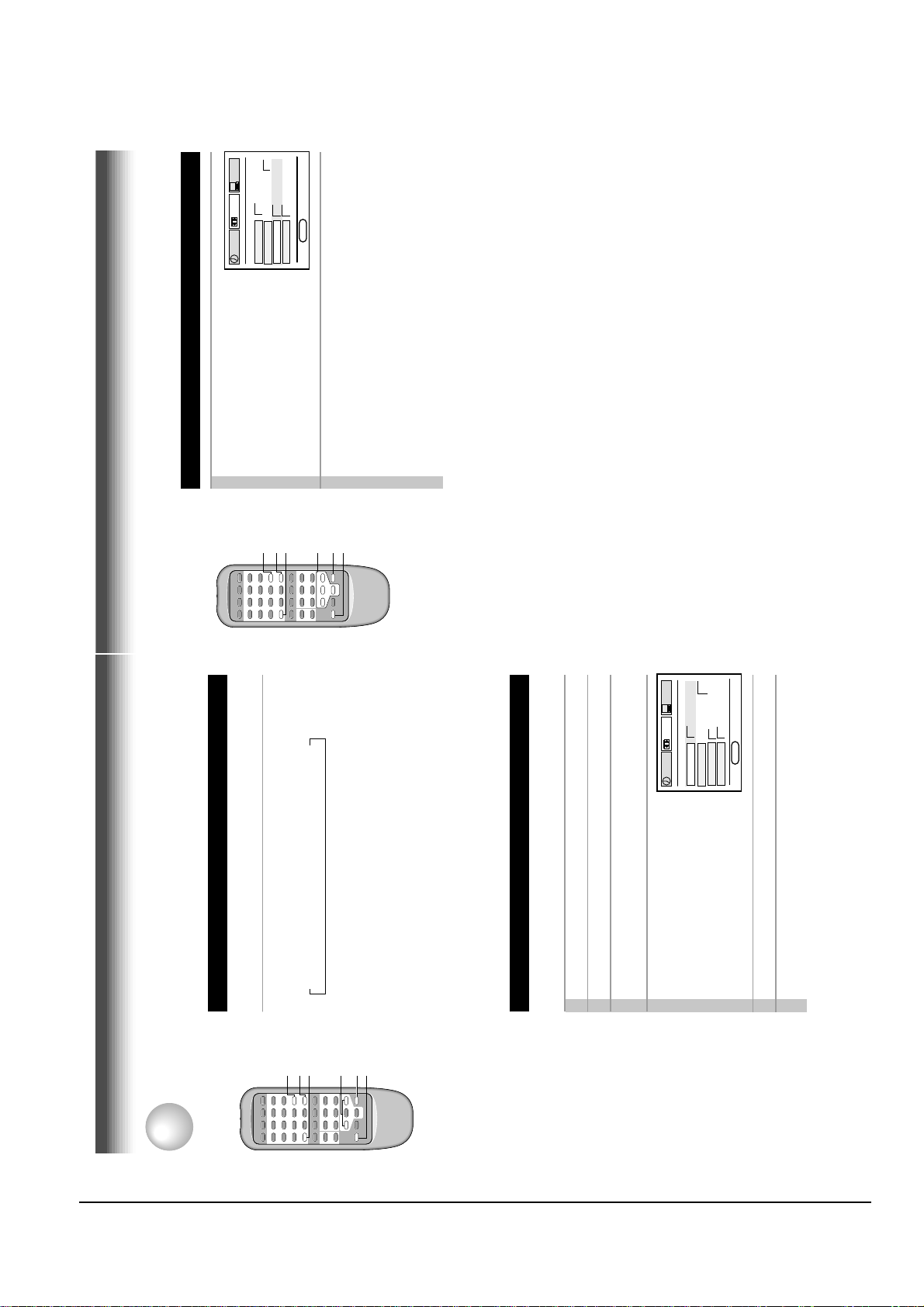
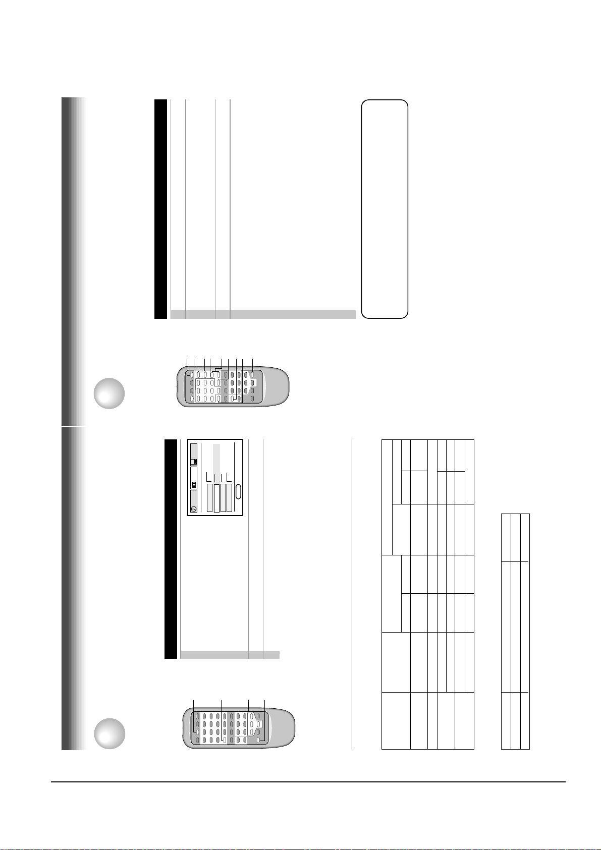
Recording the SAP/Stereo Broadcast
This VCR can receive or record MTS (Multichannel TV Sound) broadcasts. By connecting the VCR to
your stereo system or stereo TV, you will experience the SAP or stereo sound.
MTS Broadcast Compatibility
RECORDING
Preparation
Connect a stereo TV or stereo system to the AUDIO OUT jacks of the VCR.
CURSOR ( ) or ( ).
1
DISPLA Y
AUDIO
SELECT
1
Press PROG. twice to exit.
Perform a recording.
2
3
SAP (Second Audio Program broadcast):
A separate audio program, usually broadcast in a second language with the
2
R“SAP”“STEREO”
STEREO
L
Hi-Fi sound track
Contents of recorded sound
track (Mono)
Normal sound
On-Screen Display
(Press DISPLAY.)
main language.
on the SET UP
screen
Setting of “SAP SET”
Selecting a sound
Type of receiving
Sounds recorded on the tape
According to your setting of “SAP SET” on the SET UP screen, the sound is recorded onto different
broadcast
tracks of the tape as below. Set “SAP SET” to “ON” or “OFF” appropriately.
“ON” lit not lit MONO MONO SAP
“ON” or “OFF” not lit not lit MONO MONO MONO
“ON” or “OFF” not lit lit MONO (MIXED)
Regular
(monaural audio)
Stereo
“ON” lit lit MONO MONO SAP
“OFF” lit not lit MONO MONO MONO
Regular+SAP
STEREO
“OFF” lit lit MONO (MIXED)
Stereo+SAP
Sounds in playback
You can play SAP and/or stereo broadcasts with this VCR. Press AUDIO SELECT to select a desired
Sound output
SAP
Stereo
L , R indicators in the VCR display
R (right) is on.
Both R (right) and L (left) are on.
Desired sound
SAP sound
Stereo sound
sound.
Note
When the TV is connected to the RF OUT terminal of the VCR, the output sound is monaural.
28
Page 19
Reference Information
2-12 Toshiba
Brand Code
Pulser 14
Quasar 07, 15
Radio Shack 13
Brand name of your TV
Brand Code
Toshiba 01
Brand name of your TV
Table of Brand Codes
RCA 02
Bell & Howell 09
Carver 10
Celebrity 03
Realistic 09, 11, 13
Runco (NEC) 14
Citizen 12
Curtis Mathes 09, 12
Samsung 11, 12
Dumont 14
Sanyo 09
Scotch 11
Electro band 03
Emerson 09, 11
Scott 11
Sears 01, 02, 09, 10, 11
Sharp 08, 13
Sony 03
Fisher 09
GE 02, 07, 11
Gibralter 14
Goldstar 11
Soundesign 11
Supreme 03
Sylvania 10
Tandy 08
Technics 07, 15
Techwood 07
Teknika 04, 10, 12
TMK 11
Victor 05
Vidikron 10
Vidtech 11
Wards 10, 11, 13
Zenith 14
Hallmark 11
Hitachi 06
Infinity 10
JBL 10
JCB 03
JVC 05
LXI 01, 02, 09, 10, 11
Magnavox 10
Marantz 10
Megatron 06, 11
Memorex 04, 09, 11
MGA 04, 11
Midland 02, 07, 14
Mitsubishi 04, 11
Motorola 08
MTC 12
NAD 01, 11
Nikko 11
Optimus 09
Optonica 08
Panasonic 07, 10, 15
Penney 01, 02, 07, 11, 12
Philco 10
Philips 10
Princeclub 12
Prism 07
Proscan 02
Proton 11
30
Page 20
Reference Information
Toshiba 2-13
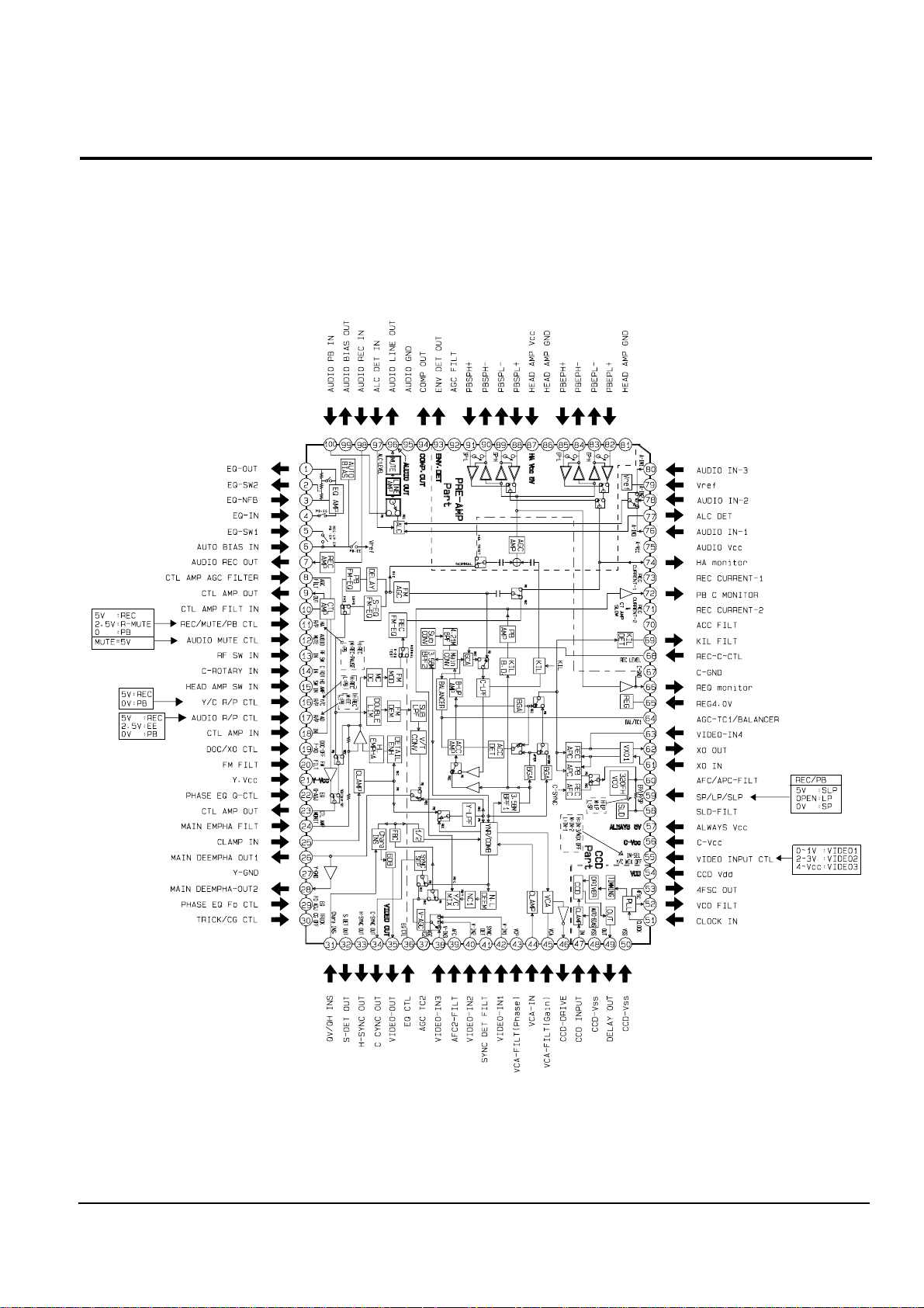
2-2-1 IC301 (LA71072M)
2-2 IC Blocks
Page 21
Reference Information
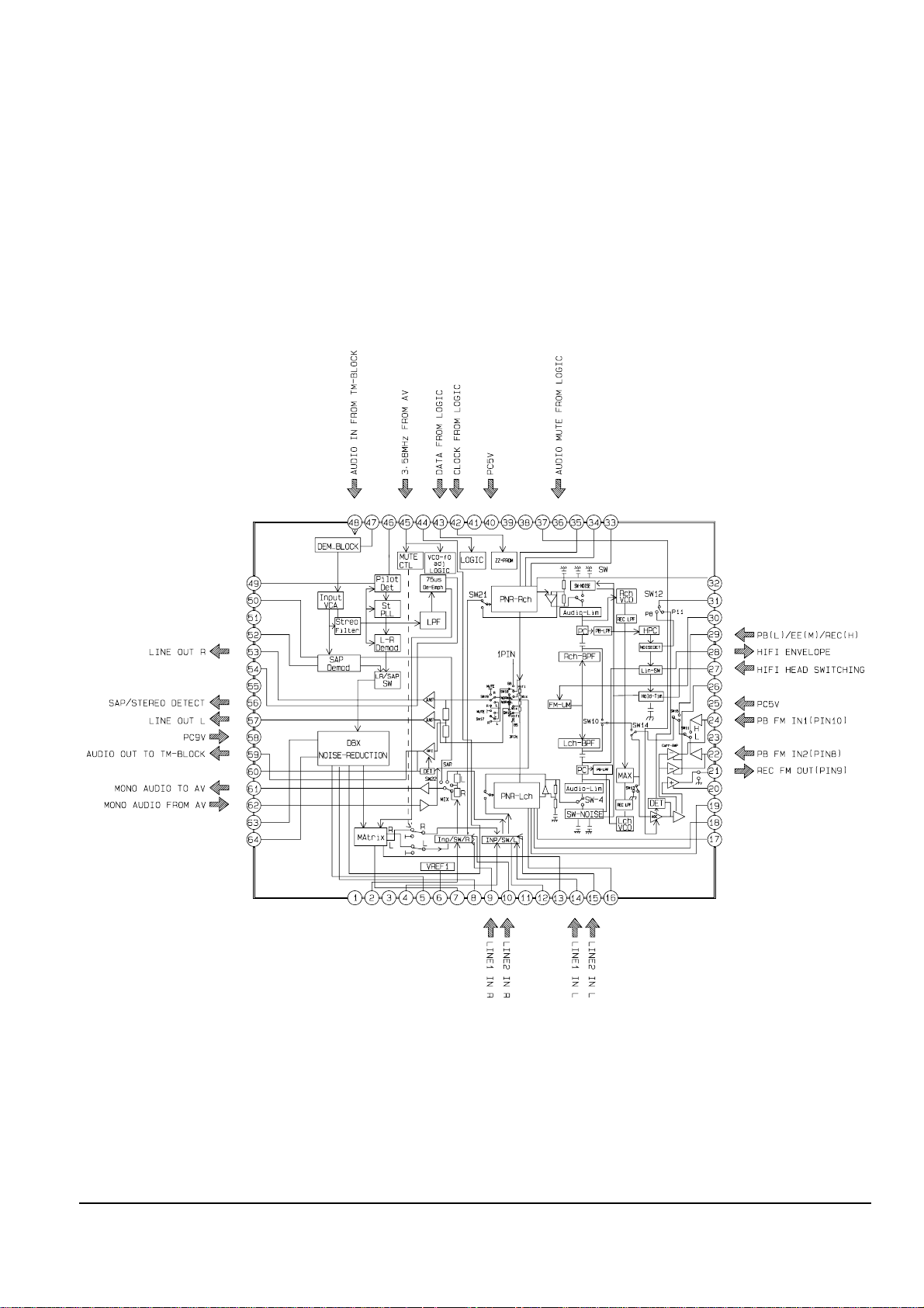
2-14 Toshiba
2-2-2 IC501 (AN3662)
Page 22
Reference Information
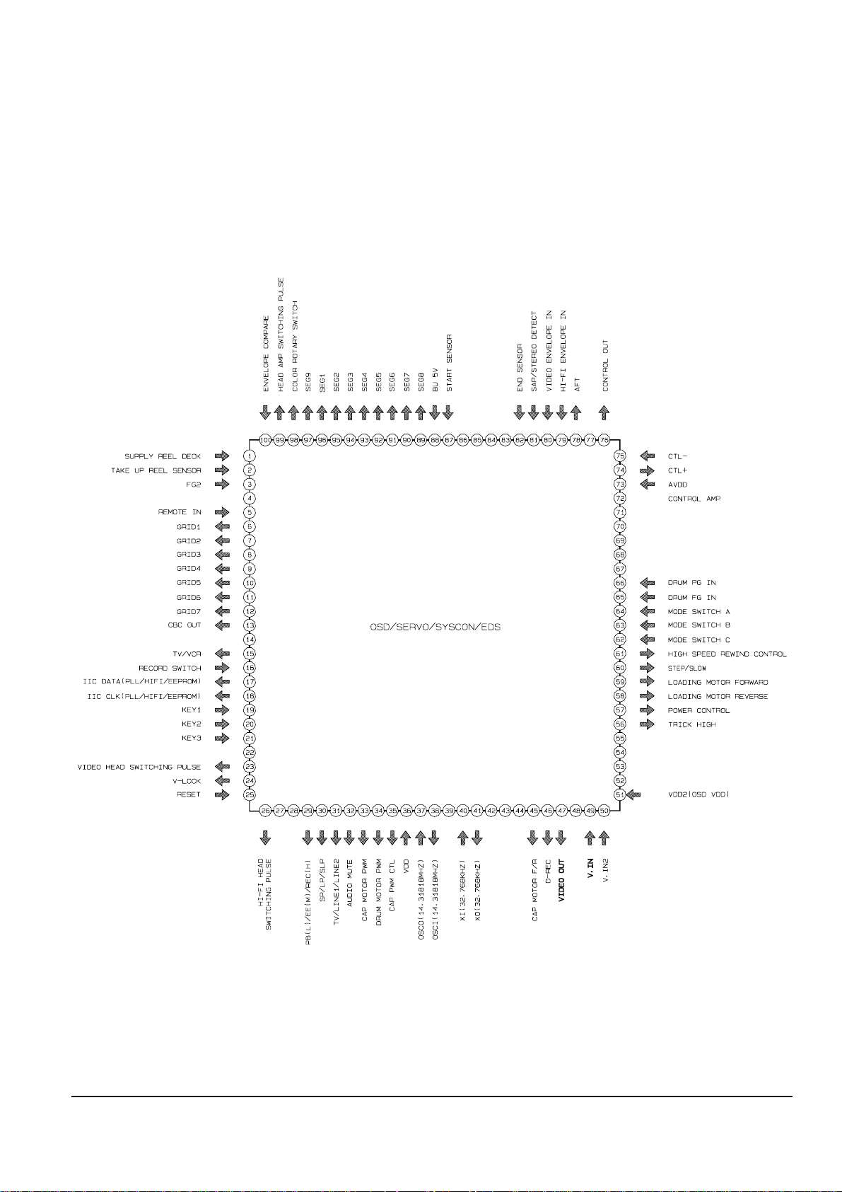
Toshiba 2-15
2-2-3 IC601 (MN101D02X)
Page 23

Reference Information
2-16 Toshiba
MEMO
Page 24

OPERATION DESCRIPTION
Toshiba 3-1
3. Product Specifications
Specifications and features are subject to change without notice.
Power supply
Power consumption
External dimensions
Mass
Channels received
Antenna input/output terminals
Signal system
Recording/Playback system
Cassette
Tape speed
Video recording/Playback time
Fast forward/Rewind time
Video input
Video output
Audio input
Audio output
Audio frequency range(Hi-Fi)
Audio dynamic range(Hi-Fi)
Utilization conditions
120V AC, 60Hz
18W
430 x 94 x 252 mm (W.H.D)
3.0 kg
VHF : Channels 2-13
UHF : Channels 14-69
CATV : Channels A7-A1, A-CC, 66-125
UHF/VHF : 75ohm F type connector
Standard NTSC
Recording : VHS format (SP, SLP)
Playback : VHS format (SP, LP, SLP)
Video cassette with VHS mark
SLP : 11.1 mm/s,
SP : 33.4 mm/s
SLP : 480 minutes,
SP : 160 minutes (When T-160 video cassette is used.)
Within approx. 120 s (When T-120 video cassette is used.)
1V(p-p), 75 ohm, unbalanced, negative sync., pin jack
1V(p-p), 75 ohm, unbalanced, negative sync., pin jack
Line input : 308 mV(rms), more than 47 Kohm, pin jack
Line input : 308 mV(rms), more than 47 Kohm, pin jack
20Hz - 20KHz
68dB
Temperature : 5°C to 40°C
Humidity : less than RH 80%
Page 25

Product Specifications
3-2 Toshiba
MEMO
Page 26
Toshiba
4-1
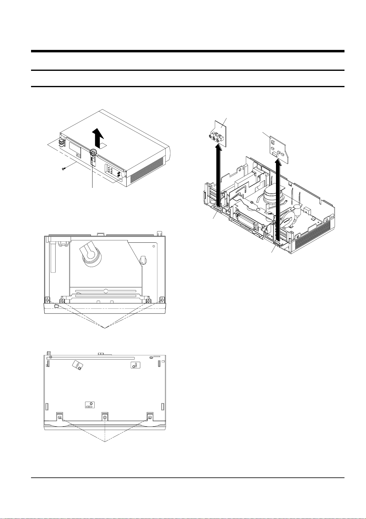
4. Disassembly and Reassembly
4-1 Cabinet Assembly
4-1-1 Cabinet Top Removal
ΠREMOVE 2 SCREWS
´ Lift up the Cabinet Top in the direction of
arrow by releasing the Hook.
Fig. 4-1 Cabinet Top Removal
4-1-2 Ass’y Front Panel Removal
Disconnect the CN701 from the Main PCB and then
lift the Jack PCB up.
CN701
CN703
Disconnect the CN703 from the Main PCB and then
lift the Key PCB up.
Fig. 4-2 Ass’y Front Panel Removal
4-1-3 Jack PCB/Key PCB Removal
Fig. 4-3 Jack PCB/Key PCB Removal
ΠRELEASE 4 HOOKS
´ RELEASE 2 HOOKS
(Top View)
(Bottom View)
Page 27
4-2
Toshiba
Disassembly and Reassembly
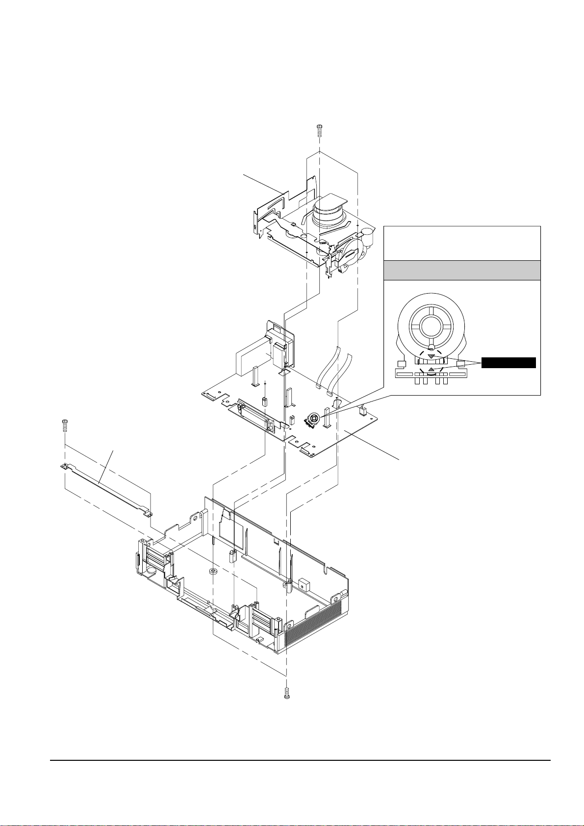
4-1-4 Chassis Removal
¨ REMOVE 3 SCREWS
ˆ LIFT THE ASS'Y FULL DECK UP.
ΠREMOVE 2 SCREWS
´ REMOVE BRACKET-FRAME
ˇ REMOVE 2 SCREWS
Ø LIFT THE ASS'Y MAIN PCB UP TO REMOVE.
MODE SWITCH
ASSEMBLY POINT
When installing the ass'y full deck on the Main PCB,
be sure to align the assembly point of mode switch.
Fig. 4-4 Chassis Removal
Page 28
Toshiba
4-3
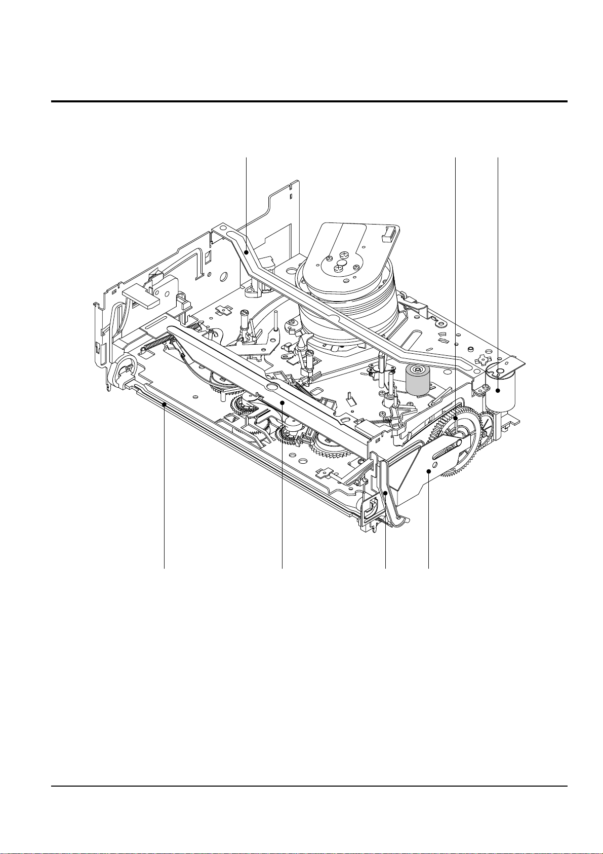
4-2 Deck Parts Locations
4-2-1 Top View
Œ
´
ˇ
¨
ˆ
Ø
∏
Fig. 4-5 Top parts Location-1
ΠBRACKET FL TOP (Optional)
´ GEAR FL CAM
ˇ MOTOR LOADING ASS’Y
¨ LEVER FL ARM ASS’Y
ˆ HOLDER FL CASSETTE ASS’Y
Ø LEVER FL DOOR
∏ SLIDER FL DRIVE
Page 29

4-4
Toshiba
Disassembly and Reassembly
Œ
´ˇ
¨
ˆ
Ø
∏
”
’
˝
Ô
Ò
ÚÆı
Ò
Fig. 4-6 Top Parts Location-2
ΠFE HEAD
´ PLATE CYLINDER C
ˇ CYLINDER ASS’Y
¨ PLATE CYLINDER B
ˆ PLATE CYLINDER A
Ø ACE HEAD ASS’Y
∏ UNIT PINCH ASS’Y
” LEVER #9 GUIDE ASS’Y
’ LEVER TENSION ASS’Y
˝ BAND BRAKE ASS’Y
Ô DISK S REEL
LEVER S BRAKE ASS’Y
Ò GEAR IDLE
Ú LEVER IDLE
Æ LEVER T BRAKE ASS’Y
ı DISK T REEL
Page 30

Disassembly and Reassembly
Toshiba
4-5
4-2-2 Bottom View
Œ
´
ˇ
¨
ˆØ∏
”
’˝
Ô
Fig. 4-7 Bottom Parts Location
ΠGEAR JOINT 1
´ GEAR JOINT 2
ˇ BRAKET GEAR
¨ MOTOR CAPSTAN ASS’Y
ˆ LEVER T LOAD ASS’Y
Ø GEAR LOADING DRIVE
∏ LEVER S LOAD ASS’Y
” HOLDER CLUTCH ASS’Y
’ BELT PULLEY
˝ SLIDER CAM
Ô SLEEVE TENSION
Page 31

4-6
Toshiba
Disassembly and Reassembly
4-3-1 Braket FL Top Removal (Optional)
1) Remove 2 screws Œ.
2) Remove the Bracket FL Top ´.
Note : Take care not to change assembly direction.
Π2 SCREWS
´ BRACKET FL TOP
4-3-2 Lever FL Door Removal
1) Rotate the Lever FL Door Πin the direction of
arrow “A”.
2) Release the Hook ´, remove the Lever FL Door Œ
in the direction of arrow “B”.
´ HOOK
ΠLEVER FL DOOR
"A"
"B"
4-3 Main Deck
Fig. 4-8 Braket FL Top Removal
Fig. 4-9 Lever FL Door Removal
Page 32

Disassembly and Reassembly
Toshiba
4-7
4-3-3 Holder FL Cassette Ass’y Removal
1) Remove the Lever FL Door. (Refer to Fig. 4-9)
2) Pull the Holder FL Cassette Ass’y Œ to the eject
position.
3) Pull the Holder FL Cassette Ass’y Œ as grasping
the Holder FL Cassette Ass’y Œ and Lever FL
Cassette-R ´ in the same time to release hooking
from Main Base until the Boss [A], [B] of Holder
FL Cassette Ass’y Œ is taken out from the Rail [C],
[D].
4) Lift the Holder FL Cassette Ass’y Œ in the direction of arrow “B” in this time, you have to grasp
the Lever FL Cassette-R ´ continuously until the
Holder FL Cassette Ass’y Œ is taken out completely.
Note : Be sure to insert Lever FL Cassette-R ´ in the
direction of “A” to prevent seperation and breakage
of the Lever FL Cassette-R ´ at disassembling and
reassembling.
ΠHOLDER FL
CASSETTE ASS'Y
´ LEVER FL CASSETTE-R
BOSS [A]
BOSS [B]
RAIL [C]
RAIL [D]
"A"
"B"
4-3-4 Lever FL Arm Ass’y Removal
1) Remove the Lever FL Door. (Refer to Fig. 4-9)
2) Remove the Holder FL Cassette Ass’y.
(Refer to Fig. 4-10)
3) Release the Hook Πin the direction of arreow
“A”, pull out the Lever FL Arm Ass’y ¨ from the
Boss of Main Base.
4) Remove the Lever FL Arm Ass’y ¨ in the direction of arrow “B”.
Assembly : When reinstalling, be sure to reassemble
Lever FL Arm Ass’y ¨ after you insert the Boss ´ in
Groove [A] of Slider FL Drive ˇ.
ΠHOOK
´ BOSS
¨ LEVER FL ARM
ASS'Y
ˇ SLIDER FL DRIVE
GROOVE [A]
"A"
"B"
Fig. 4-10 Holder FL Cassette Ass’y Removal
Fig. 4-11 Lever FL Arm Ass’y Removal
Page 33

4-8
Toshiba
Disassembly and Reassembly
4-3-5 Slider FL Drive Removal
1) Pull the Slider FL Drive Πto the front direction.
2) Remove the Slider FL Drive Πin the direction of
arrow. (Refer ti Fig. 4-12)
ΠSLIDER FL DRIVE
4-3-6 Bracket Gear, Gear FL Cam, Gear Joint 1, 2
Removal
1) Remove screw Œ.
2) Lift the Bracket Gear ´.
3) Remove the Gear FL Cam ˇ.
4) Lift the Gear Joint 2 ¨, Gear Joint 1 ˆ.
ΠSCREW
´ BRACKET GEAR
ˇ GEAR FL CAM
ˆ GEAR JOINT 1
¨ GEAR JOINT 2
Fig. 4-12 Slider FL Drive Removal
Fig. 4-13 Bracket Gear, Gear FL Cam, Gear Joint 1, 2 Removal
Page 34

Disassembly and Reassembly
Toshiba
4-9
4-3-7 Assembly of Gear FL Cam, Gear Joint 1, 2
1) Be sure to align dot mark of Gear Joint 1 Πwith
dot mark of Gear Joint 2 ´ as shown Fig. 4-14
(Refer to Timing Point 1), confirm the Timing Point
2 of the Gear Joint 2 ´ and Slider Cam ˇ.
2) Align the Gear FL Cam ¨ with the Gear Worm
Wheel Post as shown detail drawing. (Refer to
Timing Point 3)
ΠGEAR JOINT 1
´ GEAR JOINT 2
ˇ SLIDER CAM
TIMING POINT 1
¨ GEAR FL CAM
GEAR WORM WHEEL
POST
TIMING POINT 2
TIMING POINT 3
4-3-8 Holder Worm, Gear Worm, Gear Worm
Wheel Removal
1) Release the Hook [A] in the direction of arrow and,
remove the Holder Worm Œ.
2) Remove the Gear Worm ´.
3) Remove the Gear Worm Wheel ˇ. (After remov-
ing the Gear FL Cam as shown Fig. 4-13)
Note : Secure the Hook [A] after installing the Holder
Worm Œ.
ΠHOLDER WORM
´ GEAR WORM
HOOK [A]
ˇ GEAR WORM WHEEL
Fig. 4-14 Assembly of Gear FL Cam, Gear Joint 1, 2
Fig. 4-15 Holder Worm, Gear Worm, Gear Worm Wheel Removal
Page 35

4-10
Toshiba
Disassembly and Reassembly
4-3-9 Motor Loading Ass’y Removal
1) Remove the screw Œ.
2) Remove the Motor Loading Ass’y ´.
ΠSCREW
´ MOTOR LOADING ASS'Y
4-3-10 Gear Loading Drive, Slider Cam,
Lever T, S Load Ass’y Removal
1) Remove the Belt Pulley. (Refer to Fig. 4-33)
2) Remove the Gear Loading Drive Πafter releasing
Hook [A] in the direction arrow as shown in detail
drawing.
3) Remove the Slider Cam ´.
4) Remove the Lever T, S Load Ass’y ˇ, ¨.
ΠGEAR LOADING DRIVE
ˇ LEVER T LOAD ASS'Y
HOOK [A]
´ SLIDER CAM
¨ LEVER S LOAD ASS'Y
Fig. 4-16 Motor Loading Ass’y Removal
Fig. 4-17 Gear Loading Drive, Slider Cam, Lever T, S Load Ass’y
Removal
Page 36

Disassembly and Reassembly
Toshiba
4-11
4-3-11 Assembly of Gear Loading Drive,
Slider Cam, Lever T, S Load Ass’y
1) When reinstalling, be sure to align dot of Lever T
Load Ass’y Œ with dot of Lever S Load Ass’y ´
as shown in drawing. (Refer to Timing Point 1)
2) Insert the Pin A, B, C, D into the Slider Cam ˇ
hole.
3) Be sure to align dot of Lever T Load Ass’y and dot
of Gear Loading Drive ¨. (Refer to Timing Point 2)
4) Align dot of Gear Loading Drive with mark of
Slider Cam as shown in drawing.
(Refer to Timing Point 3)
´ LEVER S LOAD ASS'Y
Œ
LEVER T LOAD ASS'Y
PIN A
PIN C
PIN B
PIN D
LEVER T
LOAD ASS'Y
LEVER S
LOAD ASS'Y
ˇ SLIDER CAM
¨ GEAR LOADING DRIVE
TIMING POINT 1
TIMING POINT 2
TIMING POINT 3
4-3-12 Lever Tension Ass’y, Band Brake Ass’y,
Sleeve Tension Removal
1) Remove the Spring Tension Œ.
2) In bottom side of Deck, remove the Sleeve Tension
´ after rotating it right or left as liftinig locking
edge of Sleeve Tension.
3) Remove the side “a” of the Band Brake Ass’y ¨ in
the direction of arrow “A” from the Lever Tension
Ass’y ˇ.
4) Remove the side “b” of the Band Brake Ass’y ¨ in
the direction of arrow “B” from the Main Base.
Note :
1) When replacing the Lever Tension Ass’y, be sure to
apply oil in the Sleeve Tension.
2) Take care not to touch stain on the felt side, and
not to be folded and broken Band Brake Ass’y.
¨ BAND BRAKE ASS'Y
´ SLEEVE TENSION
ˇ LEVER TENSION ASS'Y
ΠSPRING TENSION
"A"
"B"
a
b
Fig. 4-18 Assembly of Gear Loading Drive,
Slider Cam, Lever T, S Load Ass’y
Fig. 4-19 Lever Tension Ass’y, Band Brake Ass’y, Sleeve Tension
Removal
Page 37

4-12
Toshiba
Disassembly and Reassembly
4-3-13 Lever S, T Brake Ass’y Removal
1) Release the Hook [A] and the Hook [B], [C] in the
direction of arrow as shown in Fig. 4-20.
2) Lift the Lever S, T Brake Ass’y Œ, ´ with Spring
Brake ˇ.
Assembly :
1) Assembly the Lever S Brake Ass’y Œ on the Main
Base.
2) Assembly the Lever T Brake Ass’y ´ with Spring
Brake ˇ.
Note : Take extreme care not to be folded and transformed spring Brake at removing or reinstalling.
ˇ SPRING BRAKE
´ LEVER T BRAKE ASS'Y
ΠLEVER S BRAKE ASS'Y
HOOK [A]
HOOK [C]
HOOK [B]
4-3-14 Lever Idle Ass’y Removal
1) Push the Lever Idle Πin the direction of arrow
“A”, “B”.
2) Lift the Lever Idle Œ.
Assembly :
1) Apply oil in two Bosses of Lever Idle Œ.
2) Assemble the Gear Idle ´ with the Lever Idle Œ.
Note : When replacing the Gear Idle ´, be sure to
add oil in the boss of Lever Idle Œ.
ΠLEVER IDLE
´ GEAR IDLE
´ GEAR IDLE
HOOK [A]
"A"
"B"
Fig. 4-20 Lever S, T Brake Ass’y Removal
Fig. 4-21 Lever Idle Ass’y Removal
Page 38

Disassembly and Reassembly
Toshiba
4-13
4-3-15 Disk S, T Reel Removal
1) Lift the Disk S, T Reel Œ, ´.
´ DISK T REEL
ΠDISK S REEL
4-3-16 Holder Clutch Ass’y Removal
1) Remove the Washer Slit Œ.
2) Lift the Holder Clutch Ass’y ´.
Note : When you reinstall Holder Clutch Ass’y ´.
1) Check the condition of spring as shown in
detail A.
2) Don’t push Holder Clutch Ass’y down with excessive force. Just insert Holder Clutch Ass’y into post
center with dead force and rotate it smoothly.
Be sure to confirm that spring is in the slit of
Gear Center Ass’y as shown in detail B.
´ HOLDER CLUTCH ASS'Y
ΠWASHER SLIT
<BAD>
<GOOD>
<BAD>
<GOOD>
SPRING
SPRING
DETAIL A
DETAIL B
Fig. 4-22 Disk S, T Reel Removal
Fig. 4-23 Holder Clutch Ass’y Removal
Page 39

4-14
Toshiba
Disassembly and Reassembly
4-3-17 Lever Up Down Ass’y, Gear Center Ass’y
Removal
1) Remove the 2 hooks in the direction of arrow as
shown Fig. 4-24 and lift the Lever Up Down Ass’y
Œ.
2) Lift the Gear Center Ass’y ´.
´ GEAR CENTER ASS'Y
ΠLEVER UP DOWN ASS'Y
4-3-18 Assembly of Lever Up Down Ass’y,
Gear Center Ass’y
1) Insert the Lever Up Down Ass’y Œ in the 2 rectan-
gular holes on Main Base.
2) Lift the Lever Up Down Ass’y Œ about 35 degree.
(Refer to Fig. 4-25)
3) Insert Ring ¨ of the Gear Center Ass’y ´ in the
Guide ˆ of the Lever Up Down Ass’y Œ.
4) Insert the Gear Center Ass’y ´ in the post Ø on
Main Base.
5) Push down the Lever Up Down Ass’y Œ for locking of the Hook ∏.
Note :
1) Take care not to separate and loose the Spring Up
Down.
2) When assembling the Gear Center Ass’y, don’t
push down too much.
MAIN BASE
ΠLEVER UP DOWN ASS'Y
ˆ GUDIE
´ GEAR CENTER ASS'Y
¨ RING
ˇ GEAR
Ø POST
∏ HOOK
35˚
Fig. 4-24 Lever Up Down Ass’y, Gear Center Ass’y Removal
Fig. 4-25 Assembly of Lever Up Down Ass’y, Gear Center Ass’y
Page 40

Disassembly and Reassembly
Toshiba
4-15
4-3-19 Guide Cassette Door Removal
1) Lift the Hook [A].
2) Rotate the Guide Cassette Door Πin the direction
of arrow.
Note : After reinstalling the Guide Cassette Door Œ
secure the Hook [A].
ΠGUIDE CASSETTE DOOR
HOOK [A]
4-3-20 Unit Pinch Ass’y, Plate Joint, Spring Pinch
Drive Removal
1) Lift the Unit Pinch Ass’y Œ.
2) Remove the Plate Joint ´ from Lever Pinch Drive.
3) Remove the Spring Pinch Drive ˇ.
Note :
1) Take extreme care not to touch the grease on the
Roller Pinch.
2) When reinstalling, be sure to apply grease on the
post pinch roller.
ΠUNIT PINCH ASS'Y
´ PLATE JOINT
ˇ SPRING PINCH DRIVE
Fig. 4-26 Guide Cassette Door Removal
Fig. 4-27 Unit Pinch Ass’y, Plate Joint, Spring Pinch Drive
Removal
Page 41

4-16
Toshiba
Disassembly and Reassembly
4-3-21 Lever #9 Guide Ass’y Removal
1) Remove the Spring #9 Guide Œ.
2) Lift the Lever #9 Guide Ass’y ´ in the direction of
arrow.
Note :
1) Take extreme care not to touch the grease on the
tape Guide Post.
2) After reinstalling, check the bottom side of the Post
#9 Guide to stick to the top side of Main Base.
´ LEVER #9 GUIDE ASS'Y
ΠSPRING #9 GUIDE
4-3-22 FE Head Removal
1) Remove the screw Œ.
2) Lift the FE Head ´.
ΠSCREW
´ FE HEAD
Fig. 4-28 Lever #9 Guide Ass’y Removal
Fig. 4-29 FE Head Removal
Page 42

Disassembly and Reassembly
Toshiba
4-17
4-3-23 ACE Head Removal
1) Pull out the FPC from connector of ACE Head
Ass’y ´.
2) Remove the screw Œ.
3) Lift the ACE Head Ass’y ´.
ΠSCREW
´ ACE HEAD ASS'Y
4-3-24 Slider S, T Ass’y Removal
1) Move the Slider S, T Ass’y Œ, ´ to slot, and then
lift it to remove. (Refer to arrow)
´ SLIDER T ASS'Y
ΠSLIDER S ASS'Y
Fig. 4-30 ACE Head Removal
Fig. 4-31 Slider S, T Ass’y Removal
Page 43

4-18
Toshiba
Disassembly and Reassembly
4-3-25 Cylinder Ass’y Removal
1) Remove the 3 Screws Œ, ˇ, ˆ.
2) Remove the Plate Cylinder A, B, C ´, ¨, Ø in the
direction of arrow.
3) Lift the Cylinder Ass’y ∏.
Note :
1) When reinstalling, push the Plate Cylinder A, B ¨,
Ø in the reverse of arrow and then, tighten the
2 Screws ˇ, ˆ.
2) Take care not to touch the Cylinder Ass’y and the
tape guide post at reinstalling Plate Cylinder C ´.
3) Take care not to touch the Cylinder Ass’y with
screw driver at reinstalling the Plate Cylinder C ´.
ˆ
SCREW
∏
CYLINDER ASS'Y
Œ
SCREW
´
PLATE CYLINDER C
ˇ
SCREW
¨
PLATE CYLINDER B
Ø
PLATE CYLINDER A
4-3-26 Belt Pulley Removal
1) Remove the Belt Pulley Œ.
Note : Take extreme care not to touch the grease on
Belt Pulley Πat assembling or reassembling.
ΠBELT PULLEY
Fig. 4-32 Cylinder Ass’y Removal
Fig. 4-33 Belt Pulley Removal
Page 44

Disassembly and Reassembly
Toshiba
4-19
4-3-27 Motor Capstan Ass’y Removal
1) Remove the 3 Screws Œ.
2) Remove the Motor Capstan Ass’y ´.
Assembly :
1) Match the 3 holes of Motor Capstan Ass’y ´ to the
3 holes of Main Base as attending not to drop or
knock the Motor Capstan Ass’y.
2) Tighten the 3 Screws in the direction of arrow as
shown detail drawing.
Note :
1) Don’t reuse the removed screws from Motor
Capstan Ass’y.
2) After tightening screws, check if there is gap
between the head of screws and the top side of
Main Base. There should have no gap between the
head of screws and the top side of Main Base.
3) After reinstalling, adjusting the tape transport
system again.
Π3 SCREWS
´ MOTOR CAPSTAN ASS'Y
B
C
A
<DETAIL>
4-3-28 How to Eject the Cassette Tape
(If the unit does not oprate on condition that is
inserted into housing ass’y)
1) Remove the Holder worm Πand the Gear Worm
´.
2) Turn the Gear Worm Wheel ˇ counterclockwise
with screw driver. (Refer to arrow)
ΠHOLDER WORM
´ GEAR WORM
SCREW DRIVER
ˇ GEAR WORM WHEEL
Fig. 4-34 Motor Capstan Ass’y Removal
Fig. 4-35
3) When Slider S, T are approched in the position of
unloading, rotate holder Clutch counterclockwise
after inserting screw driver in the hole of frame’s
bottom in order to wind the unwinded tape.
(Refer to Fig. 4-36)
(If you rotate Gear Worm Wheel continuously
when tape is in state of unwinding, you may cause
a tape contam
ination by grease and tape damage.
Be sure to wind the unwinded tape in the state of
set horizently.)
4) Rotate Gear Worm Wheel ˇ counterclockwise
using screw driver again up to the state of eject
mode and then pick out the tape.
(Refer to Fig. 4-35)
FRAME
Fig. 4-36
Page 45

4-20
Toshiba
Disassembly and Reassembly
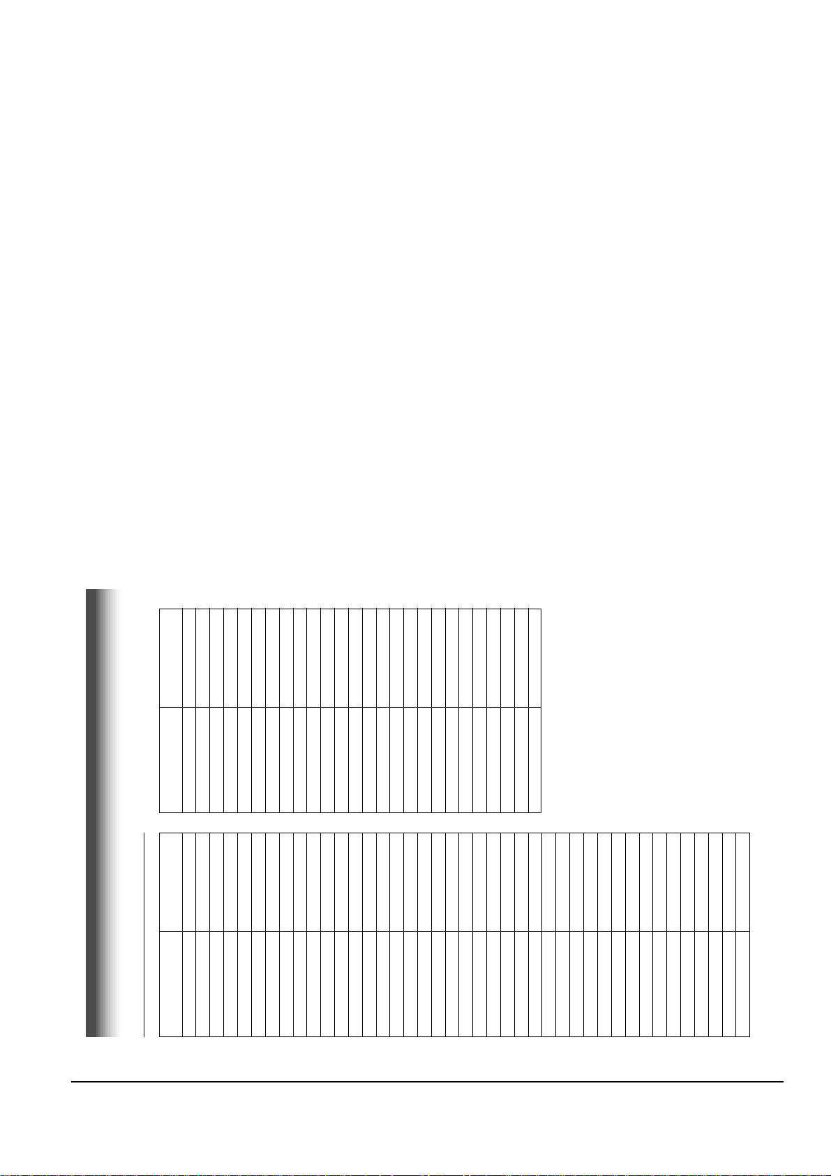
4-4 The table of clearing, Lubrication and replacement time about principal parts
1) The replacement time of parts is not life of parts.
2) The table 4-1 is that the VCR Set is in normal condition (normal temperature, normal humidity).
The checking period may be changed owing to the condition of use, runtime and environmental conditions.
3) Life of the Cylinder Ass’y is depend on the condition of use.
4) See exploded view for location of each parts.
<Tbale 4-1>
∆ : Cleaning O : Check and replacement in necessary ◆ : Add Oil
T
A
P
E
P
A
T
H
S
Y
S
T
E
M
D
R
I
V
I
N
G
* Parts Name
Checking Period
Remark
500 1000 1500 2000 2500 3000 3500 4000 4500 5000
POST TENSION ∆∆∆∆∆∆∆∆∆∆
SLANT POST S, T ∆∆∆∆∆∆∆∆∆∆
#8 GUIDE SHAFT ∆∆∆∆∆∆∆∆∆∆
CAPSTAN SHAFT ∆∆∆∆∆∆∆∆∆∆
#9 GUIDE POST ∆∆∆∆∆∆∆∆∆∆
#3 GUIDE POST ∆∆∆∆∆∆∆∆∆∆
GUIDE ROLLER S, T ∆∆∆OOOOOOO
CYLINDER ASS’Y ∆ OOOOOOOOO
FE HEAD ∆∆∆OOOOOOO
ACE HEAD ∆ OOOOOOOOO
PINCH ROLLER ∆ OOOOOOOOO
POST REEL S, T ◆◆◆◆◆
SLEEVE TENSION ◆◆◆◆◆
POST CENTER ◆ ◆◆◆◆
LEVER IDLE BOSS (2Point)
◆◆◆◆◆
CAPSTAN MOTOR PULLEY
∆∆∆∆∆OOOOO
BELT PULLEY O O O O O O O
HOLDER CLUTCH ASS’Y
∆ OOOOOOOOO
GEAR CENTER ASS’Y OOOOOOOOO
GEAR IDLE (2Point) O O O O O O O O O
LOADING MOTOR O O O O O O O O O
BAND BRAKE ASS’Y OOOOOOOOO
BRAKE T ASS’Y OOOOOOOOO
S
Y
S
T
E
M
- Periodic time of applying oil
(Apply oil after cleaning)
- The excessive applying oil may be
the cause of malfunction.
- To clean the parts, use patch and
alcohol (solvent).
- After cleaning, use the video tape
after alcohol is gone awny
completely.
- We recomnend to use oil [EP-56] or
solvent.
- One or two drops of oil should be
applied after cleaning with alcohol.
B
R
A
K
E
S
Y
S
T
E
M
Page 46

Toshiba
5-1
5. Alignment and Adjustment
5-1 Reference
1) X-Point (Tracking center) adjustment, “Head switching adjustment” and “NVRAM option setting” can be adjusted with remote control.
2) When replacing the micom (IC601) be sure to adjust the “Head switching adjustment” and “NVRAM option setting”.
3) When replacing the cylinder ass’y, be sure to adjust the “X-Point” and “Head switching adjustment”.
4) Remote control used for same chassis as a accessory is available for all adjustments.
5) How to adjustment.
- Intermittently short-circuit the test point on Main PCB with pincets to set the adjustment mode.
- If the corresponding adjustment button is pressed, the adjustment is preformed automatically.
- If the adjustment is completed, be sure to turn the power off.
5-1-1 Location of adjustment button of remote control
Fig. 5-1
X-Point (Tracking Center)
Adjustment
Head Switching Adjustment
NVRAM Option Setting
Page 47

5-2
Toshiba
Alignment and Adjustment
5-1-2 Test point location for adjustment mode setting
Fig. 5-2 Main PCB (Top View)
Short-Circuit
Page 48

Alignment and Adjustment
Toshiba
5-3
5-2 Mechanical Adjustment
5-2-1 Tape Transport System and Adjustment Locations
The tape transport system has been adjusted precisely in the factory. Alignment is not necessary except for the
following :
1) Noise observed on the screen.
2) Tape damage.
3) Parts replacement in the tape transport system.
Lower flange height of tape guide is used as the reference for the transport adjustment.
To maintain the height of the tape guide and prevent damage, do not apply excessive force onto the main base.
Fig. 5-3 Location of Tape Transport Adjustment
Fig. 5-4 Tape Travel Diagram
CYLINDER ASS'Y
TAKE UP REEL DISK
#8 GUIDE POST
#9 GUIDE POST
SUPPLY REEL DISK
CAPSTAN
PINCH ROLLER
GUIDE ROLLER "T"
GUIDE ROLLER "S"
FULL ERASE HEAD
#3 GUIDE POST
TENSION POST
HEIGHT SCREW
TILT SCREW
X - POSITION
ADJUST SILT
AZIMUTH SCREW
POST TENSION
MAIN BASE
FE HEAD CYLINDER ASS'Y PINCH ROLLER
GUIDE ROLLER "S" GUIDE ROLLER "T"
#8 GUIDE POST #9 GUIDE POST
CAPSTAN SHAFT
ACE HEAD
#3 GUIDE POST
Page 49

5-4
Toshiba
Alignment and Adjustment
5-2-2 Tape Transport System Adjustment
When parts are replaced, perform the required adjustments by referring to precedures for the tape transport
system. If there are any changes to the tape path, first run a T-120 tape and make sure excessive tape wrinkle does
not occur at the tape guides.
1) If tape wrinkle is observed at the guide roller S, T, turn the guide roller S, T until wrinkle disappears.
2) If the tape wrinkle is still observed at the tape guide, perform the tilt adjustment of the ACE head.
(1) ACE Head Assembly Adjustment
Test point : TP601 (Control Pulse)
TP602 (H’D S/W -Trigger)
TP301 (Envelope)
TP302 (Audio output)
TP303 (Video output)
Test tape : ST-N1
BLANK TAPE : T-160
Fig. 5-5 Location of Test point (Main PCB-Top View)
AUDIO OUTPUT
HEAD SWITCHING
ENVELOPE
Page 50

Alignment and Adjustment
Toshiba
5-5
a. ACE HEAD HEIGHT ADJUSTMENT
1) Run the alignment tape (Color bar) in the playback
mode.
2) Observe surface of the audio head using a dental
mirror.
3) Turn screw (C) clockwise or counterclockwise until
the gap of lower tape edge and the lower edge of
the control head is about 0.25mm.
(Refer to Fig. 5-6 and 5-7)
Fig. 5-6 Location of ACE Head Adjustment Screw
Fig. 5-7 ACE Head Height Adjustment
SCREW (A)
TLIT ADJUST
X-POSITION
ADJUSTING SLIT
SCREW (C)
HEIGHT ADJUST
SCREW (D)
X-POSITION
LOCKING
SCREW (B)
AZIMUTH ADJUST
0 ~ 0 .25 mm
AUDIO HEAD
VIDEO HEAD
CONTROL HEAD
b. ACE HEAD TILT ADJUSTMENT
1) Playback a blank tape and observe the position of
the tape at the lower flange of tape guide.
2) Confirm that there is no curl or wrinkle at the
lower flange of tape guide as shown in Fig. 5-8 (B).
3) If a curl or wrinkle of the tape occurrs, slightly
turn the screw (A) tilt adjust on the ACE head ass’y.
4) Reconfirm the ACE head height.
Fig. 5-8 Tape Guide Check
c. AUDIO AZIMUTH ADJUSTMENT
1) Load alignment tape (Mono scope) and playback
the 7KHz signal.
2) Connect channel-1 scope probe to audio output
test point (TP302).
3) Adjust screw (B) to achieve maximum audio level.
(See Fig. 5-6)
d. ACE HEAD POSITION (X-POINT) ADJUSTMENT
1) Playback the alignment tape (Color bar).
2) Intermittently short-circuit the two test points on
Main PCB to set the adjustment mode.
(See Fig. 5-2)
3) Press the “5” button of remote control then adjustment is operated automatically. (See Fig. 5-1)
4) Connect the CH-1 probe to TP301 (Envelope) the
CH-2 probe to TP602 (H’D switching pulse) and
then trigger to CH-1.
5) Insert the (-) driver into the X-Point adjustment
hole and adjust it so that envelope wavwform is
maximum.
6) Turn the Power off.
(A) (B)
(BAD)
WRINKLE
(GOOD)
Page 51

5-6
Toshiba
Alignment and Adjustment
(2) Linearity adjustment (Guide roller S, T adjustment)
1)
Playback the Mono Scope alignment tape (SP mode).
2) Observe the video envelope signal on an oscilloscope (triggered by the video switching pulse).
3) Make sure the video envelope waveform (at its
minimum) meets the specification shown in
Fig. 5-9.
If it does not, adjust as follows :
Note :
a=Maximum output of the video RF envelope.
b=Minimum output of the video RF envelope at the
entrance side.
c=Minimum output of the video RF envelope at the
center point.
d=Maximum output of the video RF envelope at the
exit side.
4) If the section A in Fig. 5-10 does not meet the specification, adjust the guide roller S up or down.
5) If the section B in Fig. 5-10 does not meet the specification, adjust the guide roller T up or down.
Fig. 5-09 Envelope Waveform Adjustment
a
a b c d
c,b,d/a
63%
bcd
Fig. 5-10 Adjustment Points
AB
A
B
H'D SWITCHING
PULSE
ENVELOPE
6) Play back the Mono Scope alignment tape (SP mode).
7) Connect an oscilloscope CH-1 to the Envelope and CH-2 to the H’D SW Pulse for triggering.
8)
Turn the guide roller heads with a flat head ( ) driver to obtain a flat video RF envelope as shown in Fig. 5-11.
Fig. 5-11 Guide Roller S, T Height Adjustment
IDEAL ENVELOPE
S HEIGHT
TOO HIGH
S HEIGHT
TOO LOW
T HEIGHT
TOO LOW
T HEIGHT
TOO HIGH
GUIDE ROLLER S
GUIDE ROLLER T
Page 52

Alignment and Adjustment
Toshiba
5-7
(3) Check Transitional Operation from RPS to Play
Check transition from RPS mode to play mode :
Using a pre-recorded SP tape, make sure the entry
side of envelope comes to an appropriate steady state
within 3 seconds (as shown in Fig. 5-12).
If the envelope waveform does not reach specified
peak-to peak amplitude within 3 seconds, adjust as
follows :
1) Make sure there is no gap between the supply
roller lower flange and the tape.
If there is a gap, adjust the supply guide roller
again.
2) Change operation mode from the RPS to the play
mode (again) and make sure the entry side of
envelope rises within 3 second.
ENTRANCE SIDE ENVELOPE
Fig. 5-12 Video Envelope Rising when Operation mode Changes
from RPS to Play Mode
(4) Envelope Check
1) Make recordings on T-120 (E-120) and T-160
(E-180) tape.
Make sure the playback output envelope meets the
specification as shown in Fig. 5-13.
2) Play back a self recorded tape (recording made on
the unit using with T-120 (E-120).
The video envelope should meet the specification
as shown in Fig. 5-13.
In SP mode, (A) should equal (B).
If the head gap is wide, upper cylinder should be
checked.
A
B
Fig. 5-13 Envelope Output and Output Level
(5) Tape Wrinkle Check
1) Run the T-160 (E-180) tape in the playback, FPS,
RPS and Pause modes and observe tape wrinkle at
each guide.
2) If excessive tape wrinkle is observed, perform the
following adjustments in Playback mode :
◆ Tape wrinkle at the guide roller S, T section :
Linearity adjustment.
◆ Tape wrinkle at tape guide flange :
ACE head assembly coarse adjustment.
Page 53

5-8
Toshiba
Alignment and Adjustment
5-2-3 Reel Torque
1) The rotation of the capstan motor causes the
holder clutch ass’y to rotat through the belt pulley.
2) The spring wrap PLAY/REV of holder clutch ass’y
drives the disk reel S, T through gear idle by rotation of gear center ass’y.
3) Brake is operated by slider cam at FF/REW mode.
4) Transportation of accurate driving force is done by
gears. (Gear Center Ass’y)
Note : If the spec. does not meet the followings specifications, replace the holder clutch ass’y and then
recheck.
4) As rotating Disk S Reel Πclockwise and the
region of adjusting in the Main Base (in shape of
slit) clockwise or counterclockwise after inserting
screw driver in the slit on Main Base. Adjust the
left end edge of Lever Tension Ass’y ˇ to 1.3
+1.5/-0.5mm from the location of mark in the
Main Base.
5) As rotating Disk S Reel Œ, double-check the location of the left end edge of Lever Tension Ass’y
and the quanity of crossing from mark on Main
Base. (+1.0/-0.5mm)
Counterclockwise : Torque UP
Clockwise : Torque DOWN
Back Tension should be 56 ± 15g.cm at inspecting it
with Back Tension Meter.
1.0mm
0.5mm
ˇ LEVER TENSION ASS'Y
ΠDISK S REEL
´ ADJUSTING
ADJUSTING SLIT
1.3
Fig. 5-16 Tension Pole and Back Tension Adjustment
5-2-4 Location adjustment and Confirmation of
Tension Post
1) Remove the holder cassette ass’y and then push
the lever FL Arm-R to the direction of loading.
2) Push the lever tension drive Πin the direction of
arrow. (See Fig. 5-14)
3) Turn the gear worm wheel ´ clockwise so that
“Timing Point” of the slider FL drive ˇ and gear
FL cam ¨ can be aligned (See Fig. 5-14)
Fig. 5-14
Fig. 5-15
¨ GEAR FL CAM
´ GEAR WORM WHEEL
ˇ SLIDER FL DRIVE
P
TIMING POINT
ΠLEVER TENSION DRIVE
LEVER TENSION
<Table 5-1>
Note :
1) Mark on Main Base is located in about 1.3mm
from inside of bending line.
2) Be careful not to deform the region of adjusting on
Main Base up and down at adjusting.
MODE TORQUE g/cm GAUGE
PB
NTSC 82.5 ± 27.5
Cassette Torquemeter
PAL 79 ±27
RPS 145 ±30 Cassette Torquemeter
Page 54

Alignment and Adjustment
Toshiba
5-9
5-3 Head Switching Point Adjustment
1) Playback the alignment tape.
2) Intermittently short-circuit the two test points on Main PCB to set the adjustment mode. (See Fig. 5-2)
3) Press the “SP/SLP” button of remote control then adjustment is operated automatically. (See Fig. 5-1)
4) Turn the Power off.
5-4 NVRAM Option Setting
1) Intermittently short-circuit the two test points on Main PCB to set the adjustment mode. (See Fig. 5-2)
2) Press the “PROG.” button of remote control about 5 seconds then option setting display is appeared.
(See Fig. 5-17)
3) Select the option number (See Table 5-2) of corresponding model with “FF” and “REW” button of remote
control.
4) If selecting the option number is completed, press the “PLAY” button of remote control.
(If “PLAY” button is pressed, the selected number is changes reversed color. ; See Fig. 5-17)
5) Press the “ENTER” button of remote control again to store the option number.
(“SAVE” is displayed for a second as shown Fig. 5-18 this setting is completed.)
6) Turn the Power off.
1) NVRAM Option is adjusted at production line basically.
2) In case Micom (IC601) and NVRAM (IC603 ; EEPROM) is replaced, be sure to set the corresponding ooption number of the repaired
model. (If the option is not set, the unit is not operated.)
ENTER : SAVE
01 02 03 04 05 06 07 08
09 10 11 12 13 14 15 16
Fig. 5-17
ENTER : SAVE
01 02 03 04 05 06 07 08
09 10 11 12 13 14 15 16
Fig. 5-18
How to identify the Type
Type
Assy-Cylinder Capstan Motor VR501
ALPS SEM Sankyo SEM Be None
A •• •
B •••
C •• •
D •• •
E •••
F •••
G •••
H •••
MODEL TYPE OPTION NUMBER
W-603C A 2, 3, 6, 8, 9, 12, 16
B 2, 3, 6, 8, 9, 12
C 2, 3, 6, 8, 12, 16
D 2, 3, 6, 8, 12
E 2, 3, 6, 9, 12, 16
F 2, 3, 6, 9, 12
G 2, 3, 6, 12, 16
H 2, 3, 6, 12
<Table 5-2>
Page 55

5-10
Toshiba
Alignment and Adjustment
How to identify the Assy-Cylinder
Fig. 5-19
ALPS Cylinder SEM Cylinder
CONNECTOR ; Pin 7 or Pin 5
CONNECTOR ; Pin 5
Fig. 5-20
How to identify the Capstan Motor
TOP VIEW
SANKYO CAPSTAN MOTOR SEM CAPSTAN MOTOR
CAPSTAN SHAFT CAPSTAN SHAFT
Page 56

Alignment and Adjustment
Toshiba
5-11
Fig. 5-21 Main PCB (Top View)
VR501
Location for VR501
Page 57

5-12
Toshiba
Alignment and Adjustment
MEMO
Page 58

Toshiba 6-1
6. Exploded View
6-1 Packing Assembly - - - - - - - - - - - - - - - - - - - - - - - - - - - - - -
6-2 Instrument Assembly - - - - - - - - - - - - - - - - - - - - - - - - - - - -
6-3 Mechanical Parts (Top Side) - - - - - - - - - - - - - - - - - - - - - - -
6-4 Mechanical Parts (Bottom Side) - - - - - - - - - - - - - - - - - - - -
6-2
6-3
6-4
6-5
Page 59

Exploded View
6-2 Toshiba
6-1 Packing Assembly
A702
A701
A702
Y101
Y102
UT01
Page 60

Exploded View
Toshiba 6-3
6-2 Instrument Assembly
153
FULL DECK (S.N.A)
BRACKET-FRAME
(S.N.A)
157
701
702
157
101
155
TM401B
601
S601A
LD601A
S602A
200
CN605B
CN303B
BOTTOM-COVER (S.N.A)
S.N.A : Service Not Available
21
22
1
31
Page 61

Exploded View
6-4 Toshiba
6-3 Mechanical Parts (Top Side)
G001
K250
K248
K110
K502
K350
K330
K182
K140
K490
K530
K240
G532
G450
K546
G510
B410
B440
B444
B446
B448
B452
G527
G520
G480
G680
(OPTIONAL)
S.N.A
S.N.A
K470
B474
S.N.A
G530
K180
K340
B473
K188
G555
G546
S.N.A : Service Not Available
K544
K542
B239
G428
G420
G458
(OPTIONAL)
Page 62

Exploded View
Toshiba 6-5
6-4 Mechanical Parts (Bottom Side)
G542
B560
B484
B257
B458
B500
B488
B257
B478
B462
B460
(OPTIONAL)
B456
B468
B464
B258
K222
K200
K225
K221
B570
B238
S.N.A : Service Not Available
Page 63

Exploded View
6-6 Toshiba
MEMO
Page 64

- PACKING PARTS -
A701 BY730518 AC69-00055L PACKING CASE;W-603C/TSB,-,326,505,150,-,
A702 BY730463 AC69-00040A CUSHION-F/B;M-686,EPS,-,-,-,-,UT01 BY634278 AC59-00019A REMOCON-ASSY;-,VC-624T,-,-,W-603/TSB,TSB
Y101 BY634262 AC68-00591A MANUAL-USERS;W-603C/TSB,MOJO100,L185,W26
Y102 BY634274 AC39-42001J CABLE-RF ASSY;#1365,-,1.2MT,75-75OHM,-,-
- INSTRUMENT PARTS -
1 BY730468 AC97-00518H ASSY-PANEL FRONT;W-603/TSB,HIPS 94V2,D/G
BY730458 AC64-00127H DOOR-CASSETTE;-,ABS94HB,-,T2.5,-,BLK,-,W
22 BY730093 AC61-62032A SPRING-MASK;X-9,-,SUS,-,4.4,-,SV-C130
31 BY730459 AC64-00133A DOOR-FRONT;-,ABS94HBGRY,-,-,-,G3019,-,W101 BY730457 AC64-00124A CABINET-TOP;-,PCM(SECC),-,T0.5,-,TM6524,
153 70790218 AC60-12126A SCREW-BH;-,BH,-,4*12,FE,FZY,-,-,155 70790082 AC60-12134A SCREW-TAP BH;-,BH,-,2-4X16,-,FE
157 70790002 AC60-10063A SCREW-TAPTITE;BH,+,-,M3,L12,ZPC3,SWRCH18
200 BY634046 AC39-10200N POWER-CORD;EP2,SPT-2,AWG#18,1.8MT,WAFER,
CN303B BY634042 3809-001110 CABLE-FLAT;30V,80C,150mm,7P,1.25mm,UL289
CN605B BY634043 3809-001112 CABLE-FLAT;30V,80C,130mm,5P,1.25mm,UL289
LD601A BY730082 AC61-21009A HOLDER-LED;-,POM(M90-44),-,BLK,-,X-9
S601A BY730080 AC61-21008A HOLDER-SENSOR;-,POM(M90-44),-,BLK,-,X-9
S602A BY730080 AC61-21008A HOLDER-SENSOR;-,POM(M90-44),-,BLK,-,X-9
- MECHANICAL PARTS -
B238 BY730087 AC61-50660A SLEEVE-TENSION;-,POM M90-44,-,-,ID3,-,-,
B239 BY730234 AC61-21004A CAP-#8 GUIDE;-,POM M90-44,-,NTR,-,X-9
B257 BY730247 AC61-50661A POST-MAIN PCB;-,POM M90-44,-,-,NTR,-,X-9
B258 BY730266 AC61-50684A GUIDE-MAIN PCB;-,POM,OD7,L20,-,BLACK,X-9
B410 BY730456 AC31-12016D MOTOR-LOADING ASSY;-,SNHNE,-,B440 BY730072 AC60-10515A SCREW-MACHINE;-,PH,+,-,M3,L3,ZPC,-,YEL
B444 BY730104 AC66-20571A GEAR-WORM;-,POM SW-01,0.5,2,-,4.5,X-9
B446 BY730079 AC61-21005A HOLDER-WORM;-,POM M90-44,-,-,-,X-9
B448 BY730105 AC66-20573A GEAR-WORM WHEEL;-,POM SW-01,0.6,11,-,6.6
B452 BY730107 AC66-20575A GEAR-FL CAM;-,POM SW-01,M0.6,Z88,-,PCD58
B456 BY730108 AC66-20576A GEAR-JOINT 1;-,POM SW-01,M1.0,Z22,-,PCD2
B458 BY730106 AC66-20574A GEAR-JOINT 2;-,POM SW-01,M1.0,Z14,-,PCD1
B460 BY730447 AC61-11045A BRACKET-GEAR;-,SECC20/20,-,T1.2,-,-,X-9
B462 BY730073 AC60-10517A SCREW-TAP TITE;-,PH,+,-,M2.6,L5,ZPC,-,YE
B464 BY730381 AC66-80140A SLIDER-CAM;-,SECC20/20,T1.2,-,-,X-9
B468 BY730450 AC66-30541A LEVER-PINCH DR ASSY;-,-,-,-,-,X-9
B473 BY730090 AC61-60559A SPRING-PINCH DRIVE;-,TS,SUS304,PI0.5,OD4
B474 BY730244 AC61-30180A PLATE-JOINT;-,SECC20/20,T0.8,-,X-9
B478 BY730449 AC66-30540A LEVER-TENS DR ASSY;-,-,-,-,-,X-9
B484 BY730110 AC66-20580A GEAR-LOADING DRIVE;-,POM SW-01,M1.0,Z32,
B488 BY730117 AC66-30543A LEVER-S LOAD ASSY;-,-,-,-,-,X-9
B500 BY730116 AC66-30542A LEVER-T LOAD ASSY;-,-,-,-,-,X-9
B560 BY730654 AC31-00006A MOTOR-CAPSTAN;-,DMVCMC07JR,-,B570 BY730071 AC60-10514A SCREW-CAPSTAN;-,PH,+,M2.6,L6,G001 BY730655 AC97-00550A ASSY-CYLINDER;CX-9TA,NTSC,6HD
G420 BY730124 AC66-80142A SLIDER-SUPPLY ASSY;-,X-9(TS),-,-,-,X-9
G428 BY730451 AC66-40153A ROLLER-SUPPLY ASSY;-,VW-32,OD7,-,X-9
G450 BY730123 AC66-80141A SLIDER-TAKE UP ASSY;-,X-9(TS),-,-,-,X-9
G458 BY730452 AC66-40154A ROLLER-TAKE UP ASSY;-,VW-32,OD7,-,X-9
G480 BY730052 AC33-00003A HEAD-ACE-ASSY;SHINHEUNG,-,-,-,-,X-9
G510 BY730479 6006-001075 SCREW-ASS’Y TAPT;WSP,PH,+,M2.6,L5.0,ZPC(
G520 BY730115 AC66-30539A LEVER-#9 GUIDE ASSY;-,X-9(TS),-,-,-,X-9
G527 BY730088 AC61-60553A SPRING-#9 GUIDE;-,ES,SUS304-WPB,OD3.1,0.
G530 BY730053 AC33-00002A HEAD-FE;-,HVFHP0038A,-,-,-,X-9
G532 BY730075 AC60-10519A SCREW-TAP TITE;-,PH,+,-,M2.6,L8,ZPC
G542 BY730122 AC66-60051A BELT-PULLEY;-,5CM-70,2 * 2,-,71.3,-,X-9
G546 BY730113 AC66-30535A LEVER-FL DOOR;-,POM M90-44,-,-,BLK,X-9
G555 BY730070 AC59-90403A UNIT-PINCH ASSY;X-9,G680 BY730372 AC66-30557A LEVER-H/CLEANER ASSY;-,POM+URETHANE,-,-,
K110 BY730102 AC66-10267A REEL-DISK S;-,POM M90-44,-,-,X-9
K140 BY730103 AC66-10268A REEL-DISK T;-,POM M90-44,-,-,X-9
K180 BY730369 AC66-30548A LEVER-IDLER ASSY;-,POM+NYLON,-,-,-,X-9
K182 BY730112 AC66-30524A LEVER-IDLER;-,POM9044,-,-,-,K188 BY730109 AC66-20577A GEAR-IDLER;-,PEBAX 7033,-,-,-,-,X-9
K200 BY730084 AC61-21012A HOLDER-CLUTCH ASSY;-,-,-,-,-,X-9
K221 BY730111 AC66-20581A GEAR-CENTER ASSY;-,POM,M=O.5,-,HIGHT T.,
K222 BY730076 AC60-30306A WASHER-SLIT;-,-,ID2.1,OD5.0,T0.5,-,POLYS
K225 BY730119 AC66-30547A LEVER-UP DOWN ASSY;-,POM+SUS,-,-,-,X-9
Toshiba 7-1
7. Replacement Parts List
Loc.No. TSB Parts No. Reference No. Description ; Specification Remark
Page 65

K240 BY730114 AC66-30538A LEVER-TENSION ASSY;-,X-9(TS),-,-,-,X-9
K248 BY730089 AC61-60554A SPRING-TENSION LEVER;-,ES,SUS304-WPB,OD3
K250 BY730094 AC63-12029A BAND-BRAKE ASSY;-,X-9(TS),-,-,-,X-9
K330 BY730121 AC66-30550A LEVER-S.BRAKE ASSY;-,POM+SUS,-,-,-,X-9
K340 BY730120 AC66-30549A LEVER-T.BRAKE ASSY;-,POM+SUS,-,-,-,X-9
K350 BY730092 AC61-60564A SPRING-BRAKE;-,TENSION,SWP-A,0.25,3,-,XK470 BY730454 AC66-80139A SLIDER-FL DRIVE;-,SECC E20/20,T1.2,-,-,X
K490 BY730083 AC61-21010B HOLDER-CASS ASSY;-,SECC+POM+SUS,-,-,SEIN
K502 BY730091 AC61-60561A SPRING-FL.LEVER-LR;-,ES,SUS304 WPB,PI2.7
K530 BY730118 AC66-30546A LEVER-FL.ARM ASS’Y;-,SECC+POM+SUS,-,-,-,
K546 BY730086 AC61-50658A GUIDE-CASS. DOOR;-,POM M90-44,-,-,NTR,-,
- ELECTRICAL PARTS -
601 BY630091 AC92-00461C ASSY-PCB-MAIN;W-603/TSB,TWIN,HI-FI,120V
701 BY630093 AC94-00037B ASSY-FUNCTION;W-607/TSB,TWIN,HI-FI,20 TS
702 BY630094 AC94-00038B ASSY-TIMER-VFD;W-609/TSB,TWIN,HI-FI,20 T
<INTERGRATED CIRCUIT>
IC1SS1 BY530004 0604-001028 PHOTO-COUPLER;TR,50-600%,250mW,DIP-4,ST
IC1SS2 BY631008 AC14-12006D IC;KA431Z,TO-92,TAPING
IC301 BY631088 1204-001644 IC-VIDEO PROCESS;LA71069M,QFP,100P,-,PLA
IC501 BY631089 1209-001264 IC-ETC, LINEAR;AN3662FBP,QFP,64P,551MIL,
IC601 BY631101 AC09-00098A IC-MICOM;MN101D02D-CC1,MN101D02D-CC1,10
IC602 BY631022 1003-001162 IC-MOTOR DRIVER;KA3082,SIP,10PIN,25MIL,D
IC603 BY631045 1103-001148 IC-EEPROM;24C021,2KBIT,DIP,8P,300MIL,10M
IC6B1 70795269 AC14-12006C IC;KA7533,DIP,-
<TRANSISTORS>
Q1P101 70693265 0501-000616 TR-SMALL SIGNAL;KSC2328A-Y,NPN,1W,TO-92L
Q1P102 70693265 0501-000616 TR-SMALL SIGNAL;KSC2328A-Y,NPN,1W,TO-92L
Q1P103 70693084 0504-000142 TR-DIGITAL;KSR2001,PNP,300MW,4.7K/4.7K,T
Q1P104 70795136 0501-000398 TR-SMALL SIGNAL;KSC945,NPN,250mW,TO-92,T
Q1P105 70795136 0501-000398 TR-SMALL SIGNAL;KSC945,NPN,250mW,TO-92,T
Q1P107 70693265 0501-000616 TR-SMALL SIGNAL;KSC2328A-Y,NPN,1W,TO-92L
Q1P108 70693084 0504-000142 TR-DIGITAL;KSR2001,PNP,300MW,4.7K/4.7K,T
Q1P109 70795136 0501-000398 TR-SMALL SIGNAL;KSC945,NPN,250mW,TO-92,T
Q1SR01 70795142 0501-000442 TR-SMALL SIGNAL;KTC3203-Y,NPN,400MW,T0-9
Q1SR02 BY530002 0502-001123 TR-POWER;KTC4419,NPN,30W,TO-220,ST,10-4
Q302 70795134 0501-000303 TR-SMALL SIGNAL;KSA733,PNP,250mW,TO-92,T
Q303 70795136 0501-000398 TR-SMALL SIGNAL;KSC945,NPN,250mW,TO-92,T
Q304 70795134 0501-000303 TR-SMALL SIGNAL;KSA733,PNP,250mW,TO-92,T
Q305 70795142 0501-000442 TR-SMALL SIGNAL;KTC3203-Y,NPN,400MW,T0-9
Q306 70795134 0501-000303 TR-SMALL SIGNAL;KSA733,PNP,250mW,TO-92,T
Q307 70795142 0501-000442 TR-SMALL SIGNAL;KTC3203-Y,NPN,400MW,T0-9
Q308 70795142 0501-000442 TR-SMALL SIGNAL;KTC3203-Y,NPN,400MW,T0-9
Q311 70795136 0501-000398 TR-SMALL SIGNAL;KSC945,NPN,250mW,TO-92,T
Q501 70795142 0501-000442 TR-SMALL SIGNAL;KTC3203-Y,NPN,400MW,T0-9
Q701 70795134 0501-000303 TR-SMALL SIGNAL;KSA733,PNP,250mW,TO-92,T
Q702 70795134 0501-000303 TR-SMALL SIGNAL;KSA733,PNP,250mW,TO-92,T
Q703 70795134 0501-000303 TR-SMALL SIGNAL;KSA733,PNP,250mW,TO-92,T
Q704 70795134 0501-000303 TR-SMALL SIGNAL;KSA733,PNP,250mW,TO-92,T
Q705 70795134 0501-000303 TR-SMALL SIGNAL;KSA733,PNP,250mW,TO-92,T
Q706 70795134 0501-000303 TR-SMALL SIGNAL;KSA733,PNP,250mW,TO-92,T
Q707 70795134 0501-000303 TR-SMALL SIGNAL;KSA733,PNP,250mW,TO-92,T
Q708 70795134 0501-000303 TR-SMALL SIGNAL;KSA733,PNP,250mW,TO-92,T
Q709 70795134 0501-000303 TR-SMALL SIGNAL;KSA733,PNP,250mW,TO-92,T
Q710 70795134 0501-000303 TR-SMALL SIGNAL;KSA733,PNP,250mW,TO-92,T
Q711 70795134 0501-000303 TR-SMALL SIGNAL;KSA733,PNP,250mW,TO-92,T
Q712 70795134 0501-000303 TR-SMALL SIGNAL;KSA733,PNP,250mW,TO-92,T
Q713 70795134 0501-000303 TR-SMALL SIGNAL;KSA733,PNP,250mW,TO-92,T
Q714 70795134 0501-000303 TR-SMALL SIGNAL;KSA733,PNP,250mW,TO-92,T
Q715 70795134 0501-000303 TR-SMALL SIGNAL;KSA733,PNP,250mW,TO-92,T
Q716 70795134 0501-000303 TR-SMALL SIGNAL;KSA733,PNP,250mW,TO-92,T
Q801 70795134 0501-000303 TR-SMALL SIGNAL;KSA733,PNP,250mW,TO-92,T
<DIODES>
D1P101 BY430003 0402-000132 DIODE-RECTIFIER;1N4004,400V,1A,DO-41,TP
D1P102 70796385 0402-000127 DIODE-RECTIFIER;1N4002,100V,1A,DO-41,TP
D1P104 BY430003 0402-000132 DIODE-RECTIFIER;1N4004,400V,1A,DO-41,TP
D1P107 BY430003 0402-000132 DIODE-RECTIFIER;1N4004,400V,1A,DO-41,TP
D1P108 70795150 0401-000101 DIODE-SWITCHING;1N4148,100V,200mA,DO-35,
D1P109 70795150 0401-000101 DIODE-SWITCHING;1N4148,100V,200mA,DO-35,
D1SD01 70795150 0401-000101 DIODE-SWITCHING;1N4148,100V,200mA,DO-35,
D1SD02 70795150 0401-000101 DIODE-SWITCHING;1N4148,100V,200mA,DO-35,
D1SR01 70795150 0401-000101 DIODE-SWITCHING;1N4148,100V,200mA,DO-35,
D1SR02 70795150 0401-000101 DIODE-SWITCHING;1N4148,100V,200mA,DO-35,
D1SS01 BY430012 0402-001196 DIODE-RECTIFIER;1T5,600V,1A,TS-1,TP
D1SS02 BY430012 0402-001196 DIODE-RECTIFIER;1T5,600V,1A,TS-1,TP
D1SS03 BY430012 0402-001196 DIODE-RECTIFIER;1T5,600V,1A,TS-1,TP
Replacement Parts List
7-2 Toshiba
Loc.No. TSB Parts No. Reference No. Description ; Specification Remark
Page 66

D1SS04 BY430012 0402-001196 DIODE-RECTIFIER;1T5,600V,1A,TS-1,TP
D1SS05 BY430008 0402-000276 DIODE-RECTIFIER;UF4007,1KV,1A,DO-41,TP
D1SS06 BY430010 0402-001194 DIODE-RECTIFIER;UG2D,200V,2A,DO-204AC,TP
D1SS07 BY430009 0402-000431 DIODE-RECTIFIER;FML-M02S,200V,2.5A,TO-22
D304 70795150 0401-000101 DIODE-SWITCHING;1N4148,100V,200mA,DO-35,
D503 70795150 0401-000101 DIODE-SWITCHING;1N4148,100V,200mA,DO-35,
D601 70795150 0401-000101 DIODE-SWITCHING;1N4148,100V,200mA,DO-35,
D603 BY430003 0402-000132 DIODE-RECTIFIER;1N4004,400V,1A,DO-41,TP
D604 BY430003 0402-000132 DIODE-RECTIFIER;1N4004,400V,1A,DO-41,TP
D605 70795150 0401-000101 DIODE-SWITCHING;1N4148,100V,200mA,DO-35,
D607 BY430003 0402-000132 DIODE-RECTIFIER;1N4004,400V,1A,DO-41,TP
D702 70795150 0401-000101 DIODE-SWITCHING;1N4148,100V,200mA,DO-35,
D703 70795150 0401-000101 DIODE-SWITCHING;1N4148,100V,200mA,DO-35,
D704 70795150 0401-000101 DIODE-SWITCHING;1N4148,100V,200mA,DO-35,
D705 70795150 0401-000101 DIODE-SWITCHING;1N4148,100V,200mA,DO-35,
D707 70795150 0401-000101 DIODE-SWITCHING;1N4148,100V,200mA,DO-35,
D708 70795150 0401-000101 DIODE-SWITCHING;1N4148,100V,200mA,DO-35,
D7F01 BY430011 0402-001195 DIODE-RECTIFIER;F1T4,400V,1.0A,TS-1,TP
D7FR01 70795150 0401-000101 DIODE-SWITCHING;1N4148,100V,200mA,DO-35,
D7FR02 70795150 0401-000101 DIODE-SWITCHING;1N4148,100V,200mA,DO-35,
W038 70796385 0402-000127 DIODE-RECTIFIER;1N4002,100V,1A,DO-41,TP
ZD1P01 70795272 0403-000390 DIODE-ZENER;UZP33B,33V,31.4-34.6V,1W,DOZD1P03 BY430013 0403-000720 DIODE-ZENER;MTZJ9.1B,9.1V,8.57-9.01V,500
ZD1P05 BY430015 0403-001211 DIODE-ZENER;MTZJ12B,11.44-12.03V,500MW,D
ZD1SR1 70795438 0403-000571 DIODE-ZENER;UZP43B,43V,40-46V,1W,DO-41,T
ZD7FT1 BY430004 0403-000509 DIODE-ZENER;MTZJ5.6B,5.6V,5.45-5.73V,500
ZD7FT2 BY430014 0403-001141 DIODE-ZENER;MTZJ24D,24V,23.63-24.85V,500
<INDUCTORS>
BD1SR1 BY330019 3301-000297 CORE-FERRITE BEAD;AA,3.6x1.2x5.7mm,1400,
BD1SS1 70795644 AC27-92001M INDUCTOR;70UH-M RT BFS3565R2F,-,-,-,FL301 BY330006 AC27-80100C COIL-OSC;7mm,2.4mH,L1P101 BY330009 2701-000002 INDUCTOR-AXIAL;100uH,10%,4.2x9.8mm
L1P102 BY330009 2701-000002 INDUCTOR-AXIAL;100uH,10%,4.2x9.8mm
L1SS01 BY330008 AC29-30050C FILTER-LINE NOISE;-,25MH,0.35A,AC250V,BS
L1SS02 70796213 AC27-12001N COIL-CHOKE;10UH-15%,RA,K-30,Q80,150KHZ,L1SS03 70796213 AC27-12001N COIL-CHOKE;10UH-15%,RA,K-30,Q80,150KHZ,L301 BY330019 3301-000297 CORE-FERRITE BEAD;AA,3.6x1.2x5.7mm,1400,
L302 BY330019 3301-000297 CORE-FERRITE BEAD;AA,3.6x1.2x5.7mm,1400,
L303 BY330019 3301-000297 CORE-FERRITE BEAD;AA,3.6x1.2x5.7mm,1400,
L304 BY330019 3301-000297 CORE-FERRITE BEAD;AA,3.6x1.2x5.7mm,1400,
L305 BY330019 3301-000297 CORE-FERRITE BEAD;AA,3.6x1.2x5.7mm,1400,
L306 70795171 2702-000120 INDUCTOR-RADIAL;15mH,5%,6.2x7.4mm
L307 70795168 2702-000108 INDUCTOR-RADIAL;100uH,5%,6x6.4mm
L501 70795168 2702-000108 INDUCTOR-RADIAL;100uH,5%,6x6.4mm
L502 BY330019 3301-000297 CORE-FERRITE BEAD;AA,3.6x1.2x5.7mm,1400,
L503 BY330019 3301-000297 CORE-FERRITE BEAD;AA,3.6x1.2x5.7mm,1400,
L504 BY330046 2701-000126 INDUCTOR-AXIAL;150uH,5%,2.4x3.4mm
L601 BY330019 3301-000297 CORE-FERRITE BEAD;AA,3.6x1.2x5.7mm,1400,
L801 70796362 2701-000168 INDUCTOR-AXIAL;3.3uH,5%,2.5x3.4mm
L802 BY330019 3301-000297 CORE-FERRITE BEAD;AA,3.6x1.2x5.7mm,1400,
<CAPACITROS>
C1P101 BY130017 2401-001730 C-AL;10uF,20%,50V,GP,TP,5x11,2.5
C1P103 BY130136 2401-002299 C-AL;4.7uF,20%,50V,GP,TP,5x7,5
C1P104 BY130136 2401-002299 C-AL;4.7uF,20%,50V,GP,TP,5x7,5
C1P105 BY130042 2401-000598 C-AL;1uF,20%,50V,GP,TP,4x7,5
C1P106 BY130249 2401-002008 C-AL;100uF,20%,16V,GP,TP,6.3x11,2.5
C1P108 BY130009 2401-001545 C-AL;47uF,20%,25V,GP,TP,6.3x7mm,2.5
C1P112 BY130136 2401-002299 C-AL;4.7uF,20%,50V,GP,TP,5x7,5
C1SD01 BY130218 2201-000445 C-CERAMIC,DISC;3.3nF,20%,400V,Y5P,TP,-,1
C1SD06 BY130270 2301-000423 C-FILM,PEF;3.3NF,5%,100V,TP,7X10X4.5MM,5
C1SR01 70795578 2401-001681 C-AL;82uF,20%,200V,GP,TP,16x26,7.5m
C1SR02 70795430 2401-000905 C-AL;22uF,20%,16V,BP,-,6x11,2.5mm
C1SR03 BY130046 2401-001235 C-AL;4.7uF,20%,250V,WT,TP,10x12.5,5
C1SR04 70795586 2301-000417 C-FILM,PEF;24nF,5%,50V,TP,6.5x10.5x4mm,5
C1SR05 70796231 2301-000176 C-FILM,PEF;18nF,5%,100V,TP,10X9X4.3X5,5m
C1SR06 70795088 2201-000930 C-CERAMIC,DISC;0.22nF,10%,500V,Y5P,TP,5.
C1SR07 70795239 2201-000795 C-CERAMIC,DISC;10nF,10%,400V,Y5P,TP,15x1
C1SS04 70795404 2201-000916 C-CERAMIC,DISC;100pF,10%,400V,Y5U,TP,10x
C1SS06 70795431 2401-000385 C-AL;10uF,20%,100V,GP,TP,6.3x11,5
C1SS07 70796014 2401-002162 C-AL;1000uF,20%,25V,WT,TP,10x20,5mm
C1SS08 BY130045 2401-001126 C-AL;330uF,20%,25V,WT,TP,10x12.5,5
C1SS10 70796210 2401-000118 C-AL;1000uF,20%,10V,GP,TP,10x12.5,5
C1SS11 70796098 2301-000129 C-FILM,PEF;100nF,5%,50V,TP,10X9X4.3X5,5m
C1SS35 BY130050 2401-003059 C-AL;1000UF,20%,16V,WT,TP,10X16,5
C301 BY130191 2203-000476 C-CERAMIC,CHIP;1000nF,+80-20%,16V,Y5V,TP
C302 BY130009 2401-001545 C-AL;47uF,20%,25V,GP,TP,6.3x7mm,2.5
C303 70796207 2203-001557 C-CERAMIC,CHIP;100nF,+80-20%,25V,Y5V,TP,
Replacement Parts List
Toshiba 7-3
Loc.No. TSB Parts No. Reference No. Description ; Specification Remark
Page 67

C304 BY130031 2203-001721 C-CERAMIC,CHIP;360pF,5%,50V,NPO,TP,2012,
C305 BY130042 2401-000598 C-AL;1uF,20%,50V,GP,TP,4x7,5
C306 70795462 2203-001584 C-CERAMIC,CHIP MELF;180PF,10%,50V,Y5E,TP
C307 70795253 2203-001637 C-CERAMIC,CHIP MELF;33PF,5%,50V,SL,TP,20
C309 70699092 2401-000918 C-AL;22uF,20%,16V,GP,-,6.3x7,5
C310 BY130273 2401-000414 C-AL;10uF,20%,16V,GP,TP,4x7,5
C311 BY130039 2203-005549 C-CERAMIC,CHIP MELF;10nF,+80-20%,16V,Y5V
C312 BY130042 2401-000598 C-AL;1uF,20%,50V,GP,TP,4x7,5
C313 BY130037 2203-005547 C-CERAMIC,CHIP MELF;22nF,+80-20%,16V,Y5V
C314 BY130273 2401-000414 C-AL;10uF,20%,16V,GP,TP,4x7,5
C315 BY130191 2203-000476 C-CERAMIC,CHIP;1000nF,+80-20%,16V,Y5V,TP
C316 BY130042 2401-000598 C-AL;1uF,20%,50V,GP,TP,4x7,5
C317 BY130042 2401-000598 C-AL;1uF,20%,50V,GP,TP,4x7,5
C318 BY130042 2401-000598 C-AL;1uF,20%,50V,GP,TP,4x7,5
C319 70795075 2202-000797 C-CERAMIC,MLC-AXIAL;10NF,30%,16V,Y5S,TP,
C320 70795075 2202-000797 C-CERAMIC,MLC-AXIAL;10NF,30%,16V,Y5S,TP,
C321 BY130027 2202-002037 C-CERAMIC,MLC-AXIAL;100nF,80-20%,50V,Y5V
C322 BY130009 2401-001545 C-AL;47uF,20%,25V,GP,TP,6.3x7mm,2.5
C323 BY130027 2202-002037 C-CERAMIC,MLC-AXIAL;100nF,80-20%,50V,Y5V
C324 BY130280 2401-002165 C-AL;100uF,20%,16V,GP,TP,6.3x7,5
C325 BY130191 2203-000476 C-CERAMIC,CHIP;1000nF,+80-20%,16V,Y5V,TP
C326 BY130042 2401-000598 C-AL;1uF,20%,50V,GP,TP,4x7,5
C327 BY130020 2203-000989 C-CERAMIC,CHIP;47nF,10%,50V,X7R,TP,2012
C328 70796207 2203-001557 C-CERAMIC,CHIP;100nF,+80-20%,25V,Y5V,TP,
C329 BY130042 2401-000598 C-AL;1uF,20%,50V,GP,TP,4x7,5
C330 BY130039 2203-005549 C-CERAMIC,CHIP MELF;10nF,+80-20%,16V,Y5V
C331 BY130042 2401-000598 C-AL;1uF,20%,50V,GP,TP,4x7,5
C332 BY130273 2401-000414 C-AL;10uF,20%,16V,GP,TP,4x7,5
C333 70796207 2203-001557 C-CERAMIC,CHIP;100nF,+80-20%,25V,Y5V,TP,
C334 BY130020 2203-000989 C-CERAMIC,CHIP;47nF,10%,50V,X7R,TP,2012
C335 BY130020 2203-000989 C-CERAMIC,CHIP;47nF,10%,50V,X7R,TP,2012
C336 70796207 2203-001557 C-CERAMIC,CHIP;100nF,+80-20%,25V,Y5V,TP,
C337 BY130049 2401-002144 C-AL;47uF,20%,16V,GP,TP,5x11,5
C338 70699092 2401-000918 C-AL;22uF,20%,16V,GP,-,6.3x7,5
C339 BY130049 2401-002144 C-AL;47uF,20%,16V,GP,TP,5x11,5
C340 BY130027 2202-002037 C-CERAMIC,MLC-AXIAL;100nF,80-20%,50V,Y5V
C341 70796207 2203-001557 C-CERAMIC,CHIP;100nF,+80-20%,25V,Y5V,TP,
C342 BY130009 2401-001545 C-AL;47uF,20%,25V,GP,TP,6.3x7mm,2.5
C343 BY130136 2401-002299 C-AL;4.7uF,20%,50V,GP,TP,5x7,5
C344 70796286 2203-001689 C-CERAMIC,CHIP MELF;8.2NF,30%,16V,Y5S,BK
C345 BY130041 2301-001014 C-FILM,PEF;6.8nF,5%,50V,TP,7x3x6,5mm
C346 70796281 2203-000260 C-CERAMIC,CHIP;10nF,10%,50V,X7R,TP,2012
C349 70795254 2203-001671 C-CERAMIC,CHIP MELF;56PF,5%,50V,Y5E,TP,2
C350 BY130049 2401-002144 C-AL;47uF,20%,16V,GP,TP,5x11,5
C351 70795075 2202-000797 C-CERAMIC,MLC-AXIAL;10NF,30%,16V,Y5S,TP,
C352 BY130145 2301-000253 C-FILM,PEF;39NF,5%,100V,TP,7.5X4.5X12.5M
C353 70796207 2203-001557 C-CERAMIC,CHIP;100nF,+80-20%,25V,Y5V,TP,
C356 BY130039 2203-005549 C-CERAMIC,CHIP MELF;10nF,+80-20%,16V,Y5V
C357 BY130017 2401-001730 C-AL;10uF,20%,50V,GP,TP,5x11,2.5
C358 BY130147 2203-000170 C-CERAMIC,CHIP;1.8nF,10%,50V,X7R,TP,2012
C359 70795753 2203-001058 C-CERAMIC,CHIP;0.56nF,5%,50V,NP0,TP,2012
C360 BY130136 2401-002299 C-AL;4.7uF,20%,50V,GP,TP,5x7,5
C361 BY130191 2203-000476 C-CERAMIC,CHIP;1000nF,+80-20%,16V,Y5V,TP
C362 BY130039 2203-005549 C-CERAMIC,CHIP MELF;10nF,+80-20%,16V,Y5V
C363 BY130039 2203-005549 C-CERAMIC,CHIP MELF;10nF,+80-20%,16V,Y5V
C364 BY130039 2203-005549 C-CERAMIC,CHIP MELF;10nF,+80-20%,16V,Y5V
C365 70795075 2202-000797 C-CERAMIC,MLC-AXIAL;10NF,30%,16V,Y5S,TP,
C366 BY130027 2202-002037 C-CERAMIC,MLC-AXIAL;100nF,80-20%,50V,Y5V
C371 BY130039 2203-005549 C-CERAMIC,CHIP MELF;10nF,+80-20%,16V,Y5V
C401 BY130039 2203-005549 C-CERAMIC,CHIP MELF;10nF,+80-20%,16V,Y5V
C403 70795075 2202-000797 C-CERAMIC,MLC-AXIAL;10NF,30%,16V,Y5S,TP,
C405 BY130049 2401-002144 C-AL;47uF,20%,16V,GP,TP,5x11,5
C406 70795075 2202-000797 C-CERAMIC,MLC-AXIAL;10NF,30%,16V,Y5S,TP,
C407 BY130037 2203-005547 C-CERAMIC,CHIP MELF;22nF,+80-20%,16V,Y5V
C409 BY130027 2202-002037 C-CERAMIC,MLC-AXIAL;100nF,80-20%,50V,Y5V
C410 70693249 2202-000807 C-CERAMIC,MLC-AXIAL;22nF,+80-20%,25V,Y5V
C501 70796207 2203-001557 C-CERAMIC,CHIP;100nF,+80-20%,25V,Y5V,TP,
C502 BY130273 2401-000414 C-AL;10uF,20%,16V,GP,TP,4x7,5
C503 BY130136 2401-002299 C-AL;4.7uF,20%,50V,GP,TP,5x7,5
C504 BY130273 2401-000414 C-AL;10uF,20%,16V,GP,TP,4x7,5
C505 BY130136 2401-002299 C-AL;4.7uF,20%,50V,GP,TP,5x7,5
C506 BY130042 2401-000598 C-AL;1uF,20%,50V,GP,TP,4x7,5
C507 BY130250 2401-002068 C-AL;33uF,20%,16V,GP,TP,5x11,5
C508 BY130273 2401-000414 C-AL;10uF,20%,16V,GP,TP,4x7,5
C509 BY130273 2401-000414 C-AL;10uF,20%,16V,GP,TP,4x7,5
C510 BY130082 2301-000224 C-FILM,PEF;22nF,5%,50V,TP,7.4x3.9x13mm,5
C511 70796207 2203-001557 C-CERAMIC,CHIP;100nF,+80-20%,25V,Y5V,TP,
C512 BY130192 2203-001550 C-CERAMIC,CHIP;1.2nF,10%,50V,X7R,TP,2012
C513 70795075 2202-000797 C-CERAMIC,MLC-AXIAL;10NF,30%,16V,Y5S,TP,
Replacement Parts List
7-4 Toshiba
Loc.No. TSB Parts No. Reference No. Description ; Specification Remark
Page 68

C514 70795075 2202-000797 C-CERAMIC,MLC-AXIAL;10NF,30%,16V,Y5S,TP,
C515 70796207 2203-001557 C-CERAMIC,CHIP;100nF,+80-20%,25V,Y5V,TP,
C516 BY130009 2401-001545 C-AL;47uF,20%,25V,GP,TP,6.3x7mm,2.5
C517 70796207 2203-001557 C-CERAMIC,CHIP;100nF,+80-20%,25V,Y5V,TP,
C518 BY130042 2401-000598 C-AL;1uF,20%,50V,GP,TP,4x7,5
C519 72531485 2401-001931 C-AL;220nF,20%,50V,-,TP,4x7mm,5
C520 BY130082 2301-000224 C-FILM,PEF;22nF,5%,50V,TP,7.4x3.9x13mm,5
C521 BY130273 2401-000414 C-AL;10uF,20%,16V,GP,TP,4x7,5
C522 BY130273 2401-000414 C-AL;10uF,20%,16V,GP,TP,4x7,5
C523 BY130250 2401-002068 C-AL;33uF,20%,16V,GP,TP,5x11,5
C526 BY130136 2401-002299 C-AL;4.7uF,20%,50V,GP,TP,5x7,5
C527 72531485 2401-001931 C-AL;220nF,20%,50V,-,TP,4x7mm,5
C528 BY130159 2401-001020 C-AL;3.3UF,20%,50V,GP,TP,4X7,5
C529 BY130042 2401-000598 C-AL;1uF,20%,50V,GP,TP,4x7,5
C530 70796207 2203-001557 C-CERAMIC,CHIP;100nF,+80-20%,25V,Y5V,TP,
C531 BY130009 2401-001545 C-AL;47uF,20%,25V,GP,TP,6.3x7mm,2.5
C532 70796207 2203-001557 C-CERAMIC,CHIP;100nF,+80-20%,25V,Y5V,TP,
C533 70796207 2203-001557 C-CERAMIC,CHIP;100nF,+80-20%,25V,Y5V,TP,
C534 70796207 2203-001557 C-CERAMIC,CHIP;100nF,+80-20%,25V,Y5V,TP,
C535 BY130273 2401-000414 C-AL;10uF,20%,16V,GP,TP,4x7,5
C536 70795769 2401-001919 C-AL;2.2uF,20%,50V,-,TP,4x7mm,5
C537 BY130273 2401-000414 C-AL;10uF,20%,16V,GP,TP,4x7,5
C538 70795075 2202-000797 C-CERAMIC,MLC-AXIAL;10NF,30%,16V,Y5S,TP,
C540 BY130009 2401-001545 C-AL;47uF,20%,25V,GP,TP,6.3x7mm,2.5
C541 70796207 2203-001557 C-CERAMIC,CHIP;100nF,+80-20%,25V,Y5V,TP,
C542 BY130273 2401-000414 C-AL;10uF,20%,16V,GP,TP,4x7,5
C543 BY130082 2301-000224 C-FILM,PEF;22nF,5%,50V,TP,7.4x3.9x13mm,5
C544 BY130273 2401-000414 C-AL;10uF,20%,16V,GP,TP,4x7,5
C546 BY130020 2203-000989 C-CERAMIC,CHIP;47nF,10%,50V,X7R,TP,2012
C547 BY130020 2203-000989 C-CERAMIC,CHIP;47nF,10%,50V,X7R,TP,2012
C548 BY130017 2401-001730 C-AL;10uF,20%,50V,GP,TP,5x11,2.5
C601 BY130039 2203-005549 C-CERAMIC,CHIP MELF;10nF,+80-20%,16V,Y5V
C602 70795075 2202-000797 C-CERAMIC,MLC-AXIAL;10NF,30%,16V,Y5S,TP,
C603 70796207 2203-001557 C-CERAMIC,CHIP;100nF,+80-20%,25V,Y5V,TP,
C604 70795075 2202-000797 C-CERAMIC,MLC-AXIAL;10NF,30%,16V,Y5S,TP,
C605 BY130009 2401-001545 C-AL;47uF,20%,25V,GP,TP,6.3x7mm,2.5
C606 70795075 2202-000797 C-CERAMIC,MLC-AXIAL;10NF,30%,16V,Y5S,TP,
C607 BY130039 2203-005549 C-CERAMIC,CHIP MELF;10nF,+80-20%,16V,Y5V
C608 BY130009 2401-001545 C-AL;47uF,20%,25V,GP,TP,6.3x7mm,2.5
C609 70796336 2203-000323 C-CERAMIC,CHIP;12nF,10%,50V,X7R,TP,2012,
C610 BY130020 2203-000989 C-CERAMIC,CHIP;47nF,10%,50V,X7R,TP,2012
C611 BY130350 2202-000253 C-CERAMIC,MLC-AXIAL;4.7nF,20%,16V,Y5R,TP
C612 70795240 2203-001577 C-CERAMIC,CHIP MELF;150PF,10%,50V,Y5E,TP
C613 BY130039 2203-005549 C-CERAMIC,CHIP MELF;10nF,+80-20%,16V,Y5V
C614 BY130280 2401-002165 C-AL;100uF,20%,16V,GP,TP,6.3x7,5
C615 70795075 2202-000797 C-CERAMIC,MLC-AXIAL;10NF,30%,16V,Y5S,TP,
C616 70796207 2203-001557 C-CERAMIC,CHIP;100nF,+80-20%,25V,Y5V,TP,
C617 BY130009 2401-001545 C-AL;47uF,20%,25V,GP,TP,6.3x7mm,2.5
C618 70795463 2203-001612 C-CERAMIC,CHIP MELF;22PF,5%,50V,SL,TP,20
C619 70795750 2203-001620 C-CERAMIC,CHIP MELF;.027NF,5%,50V,SL,BK,
C620 70795750 2203-001620 C-CERAMIC,CHIP MELF;.027NF,5%,50V,SL,BK,
C621 70795463 2203-001612 C-CERAMIC,CHIP MELF;22PF,5%,50V,SL,TP,20
C622 BY130042 2401-000598 C-AL;1uF,20%,50V,GP,TP,4x7,5
C623 BY130069 2202-000121 C-CERAMIC,MLC-AXIAL;100pF,10%,50V,Y5P,TP
C624 BY130280 2401-002165 C-AL;100uF,20%,16V,GP,TP,6.3x7,5
C625 70796207 2203-001557 C-CERAMIC,CHIP;100nF,+80-20%,25V,Y5V,TP,
C626 BY130191 2203-000476 C-CERAMIC,CHIP;1000nF,+80-20%,16V,Y5V,TP
C627 70796209 2203-001696 C-CERAMIC,CHIP MELF;82PF,10%,50V,Y5P,TP,
C628 BY130250 2401-002068 C-AL;33uF,20%,16V,GP,TP,5x11,5
C629 BY130038 2203-005548 C-CERAMIC,CHIP MELF;15nF,+80-20%,16V,Y5V
C630 BY130049 2401-002144 C-AL;47uF,20%,16V,GP,TP,5x11,5
C631 70796207 2203-001557 C-CERAMIC,CHIP;100nF,+80-20%,25V,Y5V,TP,
C632 70795254 2203-001671 C-CERAMIC,CHIP MELF;56PF,5%,50V,Y5E,TP,2
C633 BY130035 2203-005544 C-CERAMIC,CHIP MELF;3.3nF,20%,12V,Y5S,TP
C634 70795254 2203-001671 C-CERAMIC,CHIP MELF;56PF,5%,50V,Y5E,TP,2
C635 BY130039 2203-005549 C-CERAMIC,CHIP MELF;10nF,+80-20%,16V,Y5V
C636 BY130039 2203-005549 C-CERAMIC,CHIP MELF;10nF,+80-20%,16V,Y5V
C637 BY130009 2401-001545 C-AL;47uF,20%,25V,GP,TP,6.3x7mm,2.5
C638 70795075 2202-000797 C-CERAMIC,MLC-AXIAL;10NF,30%,16V,Y5S,TP,
C639 BY130027 2202-002037 C-CERAMIC,MLC-AXIAL;100nF,80-20%,50V,Y5V
C640 BY130027 2202-002037 C-CERAMIC,MLC-AXIAL;100nF,80-20%,50V,Y5V
C642 BY130020 2203-000989 C-CERAMIC,CHIP;47nF,10%,50V,X7R,TP,2012
C643 BY130039 2203-005549 C-CERAMIC,CHIP MELF;10nF,+80-20%,16V,Y5V
C644 BY130039 2203-005549 C-CERAMIC,CHIP MELF;10nF,+80-20%,16V,Y5V
C6B01 70699061 2401-000199 C-AL;1000uF,20%,6.3V,GP,TP,10x12.5,
C7F01 BY130225 2401-001353 C-AL;470uF,20%,10V,GP,TP,8x11.5,5
C7F02 BY130281 2401-003046 C-AL;47uF,20%,50V,WT,TP,6.3x11,2.5
C7F03 70795585 2301-000383 C-FILM,PEF;10nF,5%,50V,TP,6x7x3.2mm,5mm
C7FT01 70795075 2202-000797 C-CERAMIC,MLC-AXIAL;10NF,30%,16V,Y5S,TP,
Replacement Parts List
Toshiba 7-5
Loc.No. TSB Parts No. Reference No. Description ; Specification Remark
Page 69

C7FT02 BY130262 2202-000173 C-CERAMIC,MLC-AXIAL;1nF,10%,50V,Y5P,TP,1
C7FT03 BY130280 2401-002165 C-AL;100uF,20%,16V,GP,TP,6.3x7,5
C7FT04 70795075 2202-000797 C-CERAMIC,MLC-AXIAL;10NF,30%,16V,Y5S,TP,
C7FT05 BY130136 2401-002299 C-AL;4.7uF,20%,50V,GP,TP,5x7,5
C801 BY130049 2401-002144 C-AL;47uF,20%,16V,GP,TP,5x11,5
C802 BY130225 2401-001353 C-AL;470uF,20%,10V,GP,TP,8x11.5,5
C803 BY130217 2401-002042 C-AL;220uF,20%,10V,GP,TP,6.3x11,5
C804 70693215 2202-000787 C-CERAMIC,MLC-AXIAL;10PF,5%,50V,Y5P,TP,3
C805 BY130017 2401-001730 C-AL;10uF,20%,50V,GP,TP,5x11,2.5
C8F1 BY130027 2202-002037 C-CERAMIC,MLC-AXIAL;100nF,80-20%,50V,Y5V
C8F2 BY130273 2401-000414 C-AL;10uF,20%,16V,GP,TP,4x7,5
W1SR04 BY130216 2201-000812 C-CERAMIC,DISC;2.2nF,20%,400V,Y5U,BK,12.
<RESISTORS>
R1P101 70795358 2001-000857 R-CARBON;560OHM,5%,1/8W,AA,TP,1.8X3.2MM
R1P102 70795210 2007-001584 R-CHIP,MELF;2.2Kohm,5%,1/8W,DB,BK,2012
R1P104 70795025 2001-000554 R-CARBON;270OHM,5%,1/8W,AA,TP,1.8X3.2MM
R1P110 70796067 2001-000362 R-CARBON;150OHM,5%,1/8W,AA,TP,1.8X3.2MM
R1SD01 70796356 2001-000490 R-CARBON;200OHM,5%,1/8W,AA,TP,1.8X3.2MM
R1SD02 70795019 2001-000515 R-CARBON;220OHM,5%,1/8W,AA,TP,1.8X3.2MM
R1SD03 70795005 2001-000429 R-CARBON;1KOHM,5%,1/8W,AA,TP,1.8X3.2MM
R1SR01 70795002 2002-000320 R-COMPOSITION;1.8Mohm,10%,1/2W,AA,TP,3.5
R1SR02 BY230018 2003-002117 R-METAL OXIDE(S);330Kohm,5%,1W,AA,TP,3.3
R1SR03 BY230016 2003-000314 R-METAL OXIDE;47ohm,5%,2W,AE,TP,6x16mm
R1SR04 BY230016 2003-000314 R-METAL OXIDE;47ohm,5%,2W,AE,TP,6x16mm
R1SR05 70795030 2001-000003 R-CARBON;330ohm,5%,1/8W,AA,TP,1.8x3.2mm
R1SR06 70796275 2003-000119 R-METAL OXIDE;0.68ohm,5%,2W,AE,TP,6x16mm
R1SR07 70795040 2001-000734 R-CARBON;4.7KOHM,5%,1/8W,AA,TP,1.8X3.2M
R1SS01 BY230027 2003-000994 R-METAL OXIDE(S);33Kohm,5%,2W,AF,TP,3.9x
R1SS02 BY230027 2003-000994 R-METAL OXIDE(S);33Kohm,5%,2W,AF,TP,3.9x
R1SS04 70795005 2001-000429 R-CARBON;1KOHM,5%,1/8W,AA,TP,1.8X3.2MM
R1SS05 70795640 2004-000869 R-METAL;3Kohm,1%,1/8W,AA,TP,1.8x3.2mm
R1SS06 70795638 2004-000459 R-METAL;2.2Kohm,1%,1/8W,AA,TP,1.8x3.2m
R301 70796181 2007-001553 R-CHIP,MELF;2Kohm,5%,1/8W,DB,BK,2012
R302 70795221 2007-001513 R-CHIP,MELF;4.7KOHM,5%,1/8W,DB,BK,2012
R303 70796179 2007-001633 R-CHIP,MELF;1.5Kohm,5%,1/8W,DB,BK,2012
R304 70796191 2007-001555 R-CHIP,MELF;27Kohm,5%,1/8W,DB,BK,2012
R308 BY230006 2007-001561 R-CHIP,MELF;24Kohm,5%,1/8W,DB,BK,2012
R309 70795232 2007-001568 R-CHIP,MELF;22Kohm,5%,1/8W,DB,BK,2012
R310 70795225 2007-001458 R-CHIP,MELF;8.2KOHM,5%,1/8W,DB,BK,2012
R311 70795221 2007-001513 R-CHIP,MELF;4.7KOHM,5%,1/8W,DB,BK,2012
R313 70795020 2001-000449 R-CARBON;2.2KOHM,5%,1/8W,AA,TP,1.8X3.2M
R314 BY230028 2007-001456 R-CHIP,MELF;820KOHM,5%,1/8W,DB,BK,2012
R315 70796179 2007-001633 R-CHIP,MELF;1.5Kohm,5%,1/8W,DB,BK,2012
R316 70795213 2007-001629 R-CHIP,MELF;1.8Kohm,5%,1/8W,DB,BK,2012
R317 70796179 2007-001633 R-CHIP,MELF;1.5Kohm,5%,1/8W,DB,BK,2012
R318 70795225 2007-001458 R-CHIP,MELF;8.2KOHM,5%,1/8W,DB,BK,2012
R320 70795233 2007-001623 R-CHIP,MELF;10Kohm,5%,1/8W,DB,BK,2012
R326 70795023 2001-000454 R-CARBON;2.2MOHM,5%,1/8W,AA,TP,1.8X3.2M
R327 70795205 2007-001546 R-CHIP,MELF;3.9Kohm,5%,1/8W,DB,BK,2012
R329 70795238 2007-001517 R-CHIP,MELF;3KOHM,5%,1/8W,DB,BK,2012
R330 BY230019 2001-000221 R-CARBON;1.2KOHM,5%,1/8W,AA,TP,1.8X3.2M
R331 70795447 2001-000878 R-CARBON;6.2KOHM,5%,1/8W,AA,TP,1.8X3.2M
R332 70796194 2007-001448 R-CHIP,MELF;9.1KOHM,5%,1/8W,DB,BK,2012
R334 70795232 2007-001568 R-CHIP,MELF;22Kohm,5%,1/8W,DB,BK,2012
R335 70796198 2007-001505 R-CHIP,MELF;470OHM,5%,1/8W,DB,BK,2012
R336 70795213 2007-001629 R-CHIP,MELF;1.8Kohm,5%,1/8W,DB,BK,2012
R337 70796373 2007-001582 R-CHIP,MELF;2.2ohm,5%,1/8W,DB,BK,2012
R338 70795607 2001-000405 R-CARBON;180OHM,5%,1/8W,AA,TP,1.8X3.2MM
R339 70795005 2001-000429 R-CARBON;1KOHM,5%,1/8W,AA,TP,1.8X3.2MM
R340 70795005 2001-000429 R-CARBON;1KOHM,5%,1/8W,AA,TP,1.8X3.2MM
R341 70795232 2007-001568 R-CHIP,MELF;22Kohm,5%,1/8W,DB,BK,2012
R342 70795233 2007-001623 R-CHIP,MELF;10Kohm,5%,1/8W,DB,BK,2012
R344 70795011 2001-000331 R-CARBON;12KOHM,5%,1/8W,AA,TP,1.8X3.2MM
R345 70795019 2001-000515 R-CARBON;220OHM,5%,1/8W,AA,TP,1.8X3.2MM
R346 70795209 2007-001534 R-CHIP,MELF;33KOHM,5%,1/8W,DB,BK,2012
R347 70795208 2007-001589 R-CHIP,MELF;1Kohm,5%,1/8W,DB,BK,2012
R348 70795221 2007-001513 R-CHIP,MELF;4.7KOHM,5%,1/8W,DB,BK,2012
R349 70795224 2007-001495 R-CHIP,MELF;510OHM,5%,1/8W,DB,BK,2012
R350 70795224 2007-001495 R-CHIP,MELF;510OHM,5%,1/8W,DB,BK,2012
R352 70795215 2007-001497 R-CHIP,MELF;5.6KOHM,5%,1/8W,DB,BK,2012
R353 70795233 2007-001623 R-CHIP,MELF;10Kohm,5%,1/8W,DB,BK,2012
R354 70796278 2007-001538 R-CHIP,MELF;330KOHM,5%,1/8W,DB,BK,2012
R355 70795208 2007-001589 R-CHIP,MELF;1Kohm,5%,1/8W,DB,BK,2012
R356 70795234 2007-001572 R-CHIP,MELF;220Kohm,5%,1/8W,DB,BK,2012
R357 70795234 2007-001572 R-CHIP,MELF;220Kohm,5%,1/8W,DB,BK,2012
R358 70795216 2007-001601 R-CHIP,MELF;15Kohm,5%,1/8W,DB,BK,2012
R359 70795029 2001-000633 R-CARBON;30KOHM,5%,1/8W,AA,TP,1.8X3.2MM
R360 70795058 2001-000977 R-CARBON;8.2KOHM,5%,1/8W,AA,TP,1.8X3.2M
Replacement Parts List
7-6 Toshiba
Loc.No. TSB Parts No. Reference No. Description ; Specification Remark
Page 70

R361 BY230020 2007-001499 R-CHIP,MELF;5.1Kohm,5%,1/8W,DB,BK,2012
R362 70795041 2001-000786 R-CARBON;47KOHM,5%,1/8W,AA,TP,1.8X3.2MM
R363 70795213 2007-001629 R-CHIP,MELF;1.8Kohm,5%,1/8W,DB,BK,2012
R364 70796199 2007-001503 R-CHIP,MELF;47KOHM,5%,1/8W,DB,BK,2012
R367 BY230179 2001-000595 R-CARBON;3.3MOHM,5%,1/8W,AA,TP,1.8X3.2MM
R397 70795233 2007-001623 R-CHIP,MELF;10Kohm,5%,1/8W,DB,BK,2012
R401 70796198 2007-001505 R-CHIP,MELF;470OHM,5%,1/8W,DB,BK,2012
R402 70796198 2007-001505 R-CHIP,MELF;470OHM,5%,1/8W,DB,BK,2012
R501 70795215 2007-001497 R-CHIP,MELF;5.6KOHM,5%,1/8W,DB,BK,2012
R502 70795215 2007-001497 R-CHIP,MELF;5.6KOHM,5%,1/8W,DB,BK,2012
R503 70795215 2007-001497 R-CHIP,MELF;5.6KOHM,5%,1/8W,DB,BK,2012
R504 70795215 2007-001497 R-CHIP,MELF;5.6KOHM,5%,1/8W,DB,BK,2012
R506 70795209 2007-001534 R-CHIP,MELF;33KOHM,5%,1/8W,DB,BK,2012
R507 70795227 2007-001550 R-CHIP,MELF;3.3Kohm,5%,1/8W,DB,BK,2012
R510 70795004 2001-000281 R-CARBON;100OHM,5%,1/8W,AA,TP,1.8X3.2MM
R511 70796199 2007-001503 R-CHIP,MELF;47KOHM,5%,1/8W,DB,BK,2012
R512 70795004 2001-000281 R-CARBON;100OHM,5%,1/8W,AA,TP,1.8X3.2MM
R513 70796199 2007-001503 R-CHIP,MELF;47KOHM,5%,1/8W,DB,BK,2012
R514 70795039 2001-000780 R-CARBON;470OHM,5%,1/8W,AA,TP,1.8X3.2MM
R515 70795447 2001-000878 R-CARBON;6.2KOHM,5%,1/8W,AA,TP,1.8X3.2M
R516 70795039 2001-000780 R-CARBON;470OHM,5%,1/8W,AA,TP,1.8X3.2MM
R517 70796329 2007-001526 R-CHIP,MELF;36KOHM,5%,1/8W,DB,BK,2012
R518 70796194 2007-001448 R-CHIP,MELF;9.1KOHM,5%,1/8W,DB,BK,2012
R519 70795041 2001-000786 R-CARBON;47KOHM,5%,1/8W,AA,TP,1.8X3.2MM
R520 70795041 2001-000786 R-CARBON;47KOHM,5%,1/8W,AA,TP,1.8X3.2MM
R521 70699144 2001-000472 R-CARBON;2.7KOHM,5%,1/8W,AA,TP,1.8X3.2M
R522 70795211 2007-001578 R-CHIP,MELF;2.7Kohm,5%,1/8W,DB,BK,2012
R524 70795011 2001-000331 R-CARBON;12KOHM,5%,1/8W,AA,TP,1.8X3.2MM
R525 70699144 2001-000472 R-CARBON;2.7KOHM,5%,1/8W,AA,TP,1.8X3.2M
R527 70795233 2007-001623 R-CHIP,MELF;10Kohm,5%,1/8W,DB,BK,2012
R530 70796183 2007-001612 R-CHIP,MELF;12Kohm,5%,1/8W,DB,BK,2012
R531 70795507 2001-000679 R-CARBON;36KOHM,5%,1/8W,AA,TP,1.8X3.2MM
R601 70795232 2007-001568 R-CHIP,MELF;22Kohm,5%,1/8W,DB,BK,2012
R602 70795218 2007-001570 R-CHIP,MELF;220ohm,5%,1/8W,DB,BK,2012
R603 70795232 2007-001568 R-CHIP,MELF;22Kohm,5%,1/8W,DB,BK,2012
R604 70795218 2007-001570 R-CHIP,MELF;220ohm,5%,1/8W,DB,BK,2012
R605 BY230144 2001-000111 R-CARBON;150OHM,5%,1/4W,AA,TP,2.4X6.4MM
R606 70795021 2001-000522 R-CARBON;22KOHM,5%,1/8W,AA,TP,1.8X3.2MM
R607 70796196 2007-001540 R-CHIP,MELF;30KOHM,5%,1/8W,DB,BK,2012
R608 70795005 2001-000429 R-CARBON;1KOHM,5%,1/8W,AA,TP,1.8X3.2MM
R609 70795005 2001-000429 R-CARBON;1KOHM,5%,1/8W,AA,TP,1.8X3.2MM
R610 70795005 2001-000429 R-CARBON;1KOHM,5%,1/8W,AA,TP,1.8X3.2MM
R611 70796182 2007-001627 R-CHIP,MELF;100Kohm,5%,1/8W,DB,BK,2012
R613 70795040 2001-000734 R-CARBON;4.7KOHM,5%,1/8W,AA,TP,1.8X3.2M
R614 70795005 2001-000429 R-CARBON;1KOHM,5%,1/8W,AA,TP,1.8X3.2MM
R615 70795215 2007-001497 R-CHIP,MELF;5.6KOHM,5%,1/8W,DB,BK,2012
R616 70795005 2001-000429 R-CARBON;1KOHM,5%,1/8W,AA,TP,1.8X3.2MM
R617 70795230 2007-001637 R-CHIP,MELF;1.2Kohm,5%,1/8W,DB,BK,2012
R618 70795029 2001-000633 R-CARBON;30KOHM,5%,1/8W,AA,TP,1.8X3.2MM
R619 70795005 2001-000429 R-CARBON;1KOHM,5%,1/8W,AA,TP,1.8X3.2MM
R620 70795005 2001-000429 R-CARBON;1KOHM,5%,1/8W,AA,TP,1.8X3.2MM
R621 70796198 2007-001505 R-CHIP,MELF;470OHM,5%,1/8W,DB,BK,2012
R622 70796198 2007-001505 R-CHIP,MELF;470OHM,5%,1/8W,DB,BK,2012
R623 70795233 2007-001623 R-CHIP,MELF;10Kohm,5%,1/8W,DB,BK,2012
R624 70795233 2007-001623 R-CHIP,MELF;10Kohm,5%,1/8W,DB,BK,2012
R625 70795233 2007-001623 R-CHIP,MELF;10Kohm,5%,1/8W,DB,BK,2012
R626 70795237 2007-001607 R-CHIP,MELF;13Kohm,5%,1/8W,DB,BK,2012
R627 70795005 2001-000429 R-CARBON;1KOHM,5%,1/8W,AA,TP,1.8X3.2MM
R629 70795030 2001-000003 R-CARBON;330ohm,5%,1/8W,AA,TP,1.8x3.2mm
R630 70795047 2001-000864 R-CARBON;56KOHM,5%,1/8W,AA,TP,1.8X3.2MM
R631 70795047 2001-000864 R-CARBON;56KOHM,5%,1/8W,AA,TP,1.8X3.2MM
R632 70795041 2001-000786 R-CARBON;47KOHM,5%,1/8W,AA,TP,1.8X3.2MM
R633 70795234 2007-001572 R-CHIP,MELF;220Kohm,5%,1/8W,DB,BK,2012
R634 70796331 2007-001507 R-CHIP,MELF;470KOHM,5%,1/8W,DB,BK,2012
R635 70795005 2001-000429 R-CARBON;1KOHM,5%,1/8W,AA,TP,1.8X3.2MM
R637 70795005 2001-000429 R-CARBON;1KOHM,5%,1/8W,AA,TP,1.8X3.2MM
R638 70795227 2007-001550 R-CHIP,MELF;3.3Kohm,5%,1/8W,DB,BK,2012
R639 70795523 2007-000267 R-CHIP;1.8KOHM,5%,1/10W,DA,TP,2012
R641 70795208 2007-001589 R-CHIP,MELF;1Kohm,5%,1/8W,DB,BK,2012
R642 70795208 2007-001589 R-CHIP,MELF;1Kohm,5%,1/8W,DB,BK,2012
R643 70795233 2007-001623 R-CHIP,MELF;10Kohm,5%,1/8W,DB,BK,2012
R644 70795233 2007-001623 R-CHIP,MELF;10Kohm,5%,1/8W,DB,BK,2012
R645 70795233 2007-001623 R-CHIP,MELF;10Kohm,5%,1/8W,DB,BK,2012
R646 70795215 2007-001497 R-CHIP,MELF;5.6KOHM,5%,1/8W,DB,BK,2012
R647 70795030 2001-000003 R-CARBON;330ohm,5%,1/8W,AA,TP,1.8x3.2mm
R648 70795030 2001-000003 R-CARBON;330ohm,5%,1/8W,AA,TP,1.8x3.2mm
R649 70795221 2007-001513 R-CHIP,MELF;4.7KOHM,5%,1/8W,DB,BK,2012
R650 70795221 2007-001513 R-CHIP,MELF;4.7KOHM,5%,1/8W,DB,BK,2012
R651 70795221 2007-001513 R-CHIP,MELF;4.7KOHM,5%,1/8W,DB,BK,2012
Replacement Parts List
Toshiba 7-7
Loc.No. TSB Parts No. Reference No. Description ; Specification Remark
Page 71

R652 70795233 2007-001623 R-CHIP,MELF;10Kohm,5%,1/8W,DB,BK,2012
R656 70795208 2007-001589 R-CHIP,MELF;1Kohm,5%,1/8W,DB,BK,2012
R657 70795045 2001-000837 R-CARBON;51KOHM,5%,1/8W,AA,TP,1.8X3.2MM
R658 70796192 2007-001493 R-CHIP,MELF;51KOHM,5%,1/8W,DB,BK,2012
R659 70796369 2003-000259 R-METAL OXIDE;3.9OHM,5%,2W,AE,TP,6X16MM
R660 BY230030 2007-001472 R-CHIP,MELF;68KOHM,5%,1/8W,DB,BK,2012
R6B01 70796025 2001-000458 R-CARBON;2.2OHM,5%,1/8W,AA,TP,1.8X3.2MM
R6F2 70796199 2007-001503 R-CHIP,MELF;47KOHM,5%,1/8W,DB,BK,2012
R701 70795233 2007-001623 R-CHIP,MELF;10Kohm,5%,1/8W,DB,BK,2012
R702 70795233 2007-001623 R-CHIP,MELF;10Kohm,5%,1/8W,DB,BK,2012
R704 70795233 2007-001623 R-CHIP,MELF;10Kohm,5%,1/8W,DB,BK,2012
R705 70795233 2007-001623 R-CHIP,MELF;10Kohm,5%,1/8W,DB,BK,2012
R706 70795233 2007-001623 R-CHIP,MELF;10Kohm,5%,1/8W,DB,BK,2012
R707 70795233 2007-001623 R-CHIP,MELF;10Kohm,5%,1/8W,DB,BK,2012
R708 70795006 2001-000290 R-CARBON;10KOHM,5%,1/8W,AA,TP,1.8X3.2MM
R709 70795006 2001-000290 R-CARBON;10KOHM,5%,1/8W,AA,TP,1.8X3.2MM
R712 70795006 2001-000290 R-CARBON;10KOHM,5%,1/8W,AA,TP,1.8X3.2MM
R714 70795006 2001-000290 R-CARBON;10KOHM,5%,1/8W,AA,TP,1.8X3.2MM
R716 70795006 2001-000290 R-CARBON;10KOHM,5%,1/8W,AA,TP,1.8X3.2MM
R718 70795006 2001-000290 R-CARBON;10KOHM,5%,1/8W,AA,TP,1.8X3.2MM
R720 70795006 2001-000290 R-CARBON;10KOHM,5%,1/8W,AA,TP,1.8X3.2MM
R722 70795006 2001-000290 R-CARBON;10KOHM,5%,1/8W,AA,TP,1.8X3.2MM
R724 70795233 2007-001623 R-CHIP,MELF;10Kohm,5%,1/8W,DB,BK,2012
R733 70795006 2001-000290 R-CARBON;10KOHM,5%,1/8W,AA,TP,1.8X3.2MM
R741 70795040 2001-000734 R-CARBON;4.7KOHM,5%,1/8W,AA,TP,1.8X3.2M
R743 70795040 2001-000734 R-CARBON;4.7KOHM,5%,1/8W,AA,TP,1.8X3.2M
R744 70795040 2001-000734 R-CARBON;4.7KOHM,5%,1/8W,AA,TP,1.8X3.2M
R745 70795054 2001-000969 R-CARBON;75OHM,5%,1/8W,AA,TP,1.8X3.2MM
R7F01 70795009 2001-000440 R-CARBON;1OHM,5%,1/8W,AA,TP,1.8X3.2MM
R7F02 BY230023 2001-000036 R-CARBON;330OHM,5%,1/4W,AA,TP,2.4X6.4MM
R7FT01 BY230026 2001-000982 R-CARBON;8.2OHM,5%,1/4W,AA,TP,2.4X6.4MM
R7FT02 BY230026 2001-000982 R-CARBON;8.2OHM,5%,1/4W,AA,TP,2.4X6.4MM
R7FT03 70795007 2001-000273 R-CARBON;100KOHM,5%,1/8W,AA,TP,1.8X3.2M
R7FT04 70795007 2001-000273 R-CARBON;100KOHM,5%,1/8W,AA,TP,1.8X3.2M
R7FT05 70795007 2001-000273 R-CARBON;100KOHM,5%,1/8W,AA,TP,1.8X3.2M
R7FT06 70795007 2001-000273 R-CARBON;100KOHM,5%,1/8W,AA,TP,1.8X3.2M
R7FT07 70795007 2001-000273 R-CARBON;100KOHM,5%,1/8W,AA,TP,1.8X3.2M
R7FT08 70795007 2001-000273 R-CARBON;100KOHM,5%,1/8W,AA,TP,1.8X3.2M
R7FT09 70795007 2001-000273 R-CARBON;100KOHM,5%,1/8W,AA,TP,1.8X3.2M
R7FT10 70795007 2001-000273 R-CARBON;100KOHM,5%,1/8W,AA,TP,1.8X3.2M
R7FT11 70795007 2001-000273 R-CARBON;100KOHM,5%,1/8W,AA,TP,1.8X3.2M
R7FT12 70795007 2001-000273 R-CARBON;100KOHM,5%,1/8W,AA,TP,1.8X3.2M
R7FT13 70795007 2001-000273 R-CARBON;100KOHM,5%,1/8W,AA,TP,1.8X3.2M
R7FT14 70795007 2001-000273 R-CARBON;100KOHM,5%,1/8W,AA,TP,1.8X3.2M
R7FT15 70795007 2001-000273 R-CARBON;100KOHM,5%,1/8W,AA,TP,1.8X3.2M
R7FT16 70795007 2001-000273 R-CARBON;100KOHM,5%,1/8W,AA,TP,1.8X3.2M
R7FT17 70795007 2001-000273 R-CARBON;100KOHM,5%,1/8W,AA,TP,1.8X3.2M
R7FT18 70795007 2001-000273 R-CARBON;100KOHM,5%,1/8W,AA,TP,1.8X3.2M
R7FT19 70795029 2001-000633 R-CARBON;30KOHM,5%,1/8W,AA,TP,1.8X3.2MM
R7FT20 70795006 2001-000290 R-CARBON;10KOHM,5%,1/8W,AA,TP,1.8X3.2MM
R801 70795713 2007-001460 R-CHIP,MELF;75OHM,5%,1/8W,DB,BK,2012
R802 BY230021 2001-000025 R-CARBON;75OHM,5%,1/4W,AA,TP,2.4X6.4MM
R803 70795353 2001-001026 R-CARBON;910OHM,5%,1/8W,AA,TP,1.8X3.2MM
R804 70795713 2007-001460 R-CHIP,MELF;75OHM,5%,1/8W,DB,BK,2012
R8F1 70795208 2007-001589 R-CHIP,MELF;1Kohm,5%,1/8W,DB,BK,2012
R8F2 70795041 2001-000786 R-CARBON;47KOHM,5%,1/8W,AA,TP,1.8X3.2MM
<MISCELLANEOUS>
CN1SS1 70796223 3711-000178 CONNECTOR-HEADER;1WALL,2P,1R,3.96mm,STRA
CN301 70796387 3708-000391 CONNECTOR-FPC/FC/PIC;10P,1.25MM,STRAIGHT
CN302 70796246 3711-002445 CONNECTOR-HEADER;BOX,2P,2R,1.5MM,STRAIGH
CN303 BY634038 3708-001302 CONNECTOR-FPC/FC/PIC;7P,1.25mm,STRAIGHT,
CN601 BY634047 AC39-20817S LEAD CONNECTOR-ASSY;DP,SMH200-02,YBH200CN604 BY634026 3711-003749 CONNECTOR-HEADER;BOX,8P,2R,2mm,STRAIGHT,
CN605 BY634003 3708-001163 CONNECTOR-FPC/FC/PIC;5P,1.25mm,STRAIGHT,
CN701 BY634040 3711-004013 CONNECTOR-HEADER;3WALL,10P,1R,2mm,STRAIG
CN703 BY634040 3711-004013 CONNECTOR-HEADER;3WALL,10P,1R,2mm,STRAIG
CN705 BY634064 3711-004191 CONNECTOR-HEADER;1WALL,2P,1R,5MM,ANGLE,S
CN7FT1 BY634039 3710-001385 CONNECTOR-SOCKET;10P,1R,2mm,ANGLE,SN
CN7FT1 BY634041 3711-004051 CONNECTOR-HEADER;NOWALL,24P,1R,2.5MM,ANG
CN7FT2 BY634269 3710-001564 CONNECTOR-SOCKET;11P,1R,2mm,ANGLE,SN
DT701 BY634044 AC07-20051B VF-DISPLAY;SVV-07SS26,9SEG,20.5x75.0,M68
F1SD01 70795420 3601-001122 FUSE-CARTRIDGE;250V,1.6A,FAST-ACTING,GLA
JK7W01 BY634273 AC37-00013A JACK—PIN;-,-,3P,BLK,DPSE-9946
JK801 BY634001 AC37-20001G JACK-RCA;DPAE-,6P,HIFI,PI3.3
LD601 BY430016 0601-000517 LED-IR;RECTANGULA,4x6.0mm,75mW,6V,950
PT1SD1 BY634270 AC26-00001E TRANS-SWITCHING;-,230V,DEMCO,EE2821,1.3M
PT601 BY530005 0604-001122 PHOTO-INTERRUPTER;TR,0.065%,150mW,DIP-4,
PT602 BY530005 0604-001122 PHOTO-INTERRUPTER;TR,0.065%,150mW,DIP-4,
Replacement Parts List
7-8 Toshiba
Loc.No. TSB Parts No. Reference No. Description ; Specification Remark
Page 72

RM7FT1 BY634036 AC59-60060A MODULE-REMOCON;GP1U281R,SHARP,38KHZ,-,-,
S601 BY530003 0603-001011 PHOTO-TR;NPN,35V,6V,50mA,75mW,BK
S602 BY530003 0603-001011 PHOTO-TR;NPN,35V,6V,50mA,75mW,BK
SW401 BY632003 3408-001042 SWITCH-SLIDE;DC 12V,100mA,-,OFF-ON,SW602 BY632005 AC34-20100B SWITCH-REC;-,-,X-9,SW603 BY632004 AC34-20100A SWITCH-MODE;-,-,X-9,SW7W01 BY632001 3404-000165 SWITCH-TACT;12V,50mA,160gf,6x6mm,SPST
SW7W02 BY632001 3404-000165 SWITCH-TACT;12V,50mA,160gf,6x6mm,SPST
SW7W03 BY632001 3404-000165 SWITCH-TACT;12V,50mA,160gf,6x6mm,SPST
SW7W04 BY632001 3404-000165 SWITCH-TACT;12V,50mA,160gf,6x6mm,SPST
SW7W06 BY632001 3404-000165 SWITCH-TACT;12V,50mA,160gf,6x6mm,SPST
SW7W07 BY632001 3404-000165 SWITCH-TACT;12V,50mA,160gf,6x6mm,SPST
SW7W08 BY632001 3404-000165 SWITCH-TACT;12V,50mA,160gf,6x6mm,SPST
SW7W09 BY632001 3404-000165 SWITCH-TACT;12V,50mA,160gf,6x6mm,SPST
SWTW05 BY632001 3404-000165 SWITCH-TACT;12V,50mA,160gf,6x6mm,SPST
TM401 BY634275 AC40-00007A TM-BLOCK;115VD025AP,NTSC-M,115VD025AP,Y
VA1SS1 BY634022 1405-001026 VARISTOR;470V,600A,9x7mm,TP
VR501 70795065 2103-000171 VR-SEMI;10Kohm,30%,1/10W,TOP
XT301 BY633004 2801-003610 CRYSTAL-UNIT;3.579545MHz,8ppm,28-AAA,S,1
XT601 70796216 2801-001384 CRYSTAL-UNIT;14.31818MHz,30ppm,28-AAA,16
XT602 BY633003 2801-003318 CRYSTAL-UNIT;32.768KHz,20ppm,28-AAP,12.5
Replacement Parts List
Toshiba 7-9
Loc.No. TSB Parts No. Reference No. Description ; Specification Remark
Page 73

Replacement Parts List
7-10 Toshiba
MEMO
Page 74

Toshiba 8-1
8. Block Diagram
Page 75

Block Diagram
8-2 Toshiba
MEMO
Page 76

Toshiba 9-1
9. PCB Diagrams
9-2
9-3
9-3
9-3
9-1 Main - - - - - - - - - - - - - - - - - - - - - - - - - - - - - - - - - - - - - - - - - - - - - - - - - -
9-2 VFD - - - - - - - - - - - - - - - - - - - - - - - - - - - - - - - - - - - - - - - - - - - - - - - - - - -
9-3 Jack - - - - - - - - - - - - - - - - - - - - - - - - - - - - - - - - - - - - - - - - - - - - - - - - - -
9-4 Key - - - - - - - - - - - - - - - - - - - - - - - - - - - - - - - - - - - - - - - - - - - - - - - - - - -
Page 77

PCB Diagrams
9-2 Toshiba
9-1 Main
Page 78

PCB Diagrams
Toshiba 9-3
9-2 VFD
9-3 Jack 9-4 Key
Page 79

PCB Diagrams
9-4 Toshiba
MEMO
Page 80

Toshiba 10-1
10. Schematic Diagrams
10-2
10-3
10-4
10-6
10-8
10-10
10-11
10-12
◆ Block Identification of Main PCB - - - - - - - - - - - - - - - - - - - - - - - - - - - - - - -
10-1 S.M.P.S./Power - - - - - - - - - - - - - - - - - - - - - - - - - - - - - - - - - - - - - - - - -
10-2 Logic - - - - - - - - - - - - - - - - - - - - - - - - - - - - - - - - - - - - - - - - - - - - - - - -
10-3 A/V - - - - - - - - - - - - - - - - - - - - - - - - - - - - - - - - - - - - - - - - - - - - - - - - -
10-4 Hi-Fi/MTS - - - - - - - - - - - - - - - - - - - - - - - - - - - - - - - - - - - - - - - - - - - - -
10-5 TM-Block/Input-Output - - - - - - - - - - - - - - - - - - - - - - - - - - - - - - - - - - - -
10-6 VFD - - - - - - - - - - - - - - - - - - - - - - - - - - - - - - - - - - - - - - - - - - - - - - - - -
10-7 Remote-Control - - - - - - - - - - - - - - - - - - - - - - - - - - - - - - - - - - - - - - - - -
Page 81

Schematic Diagrams
10-2 Toshiba
For schematic Diagram
- Resistors are in ohms, 1/8W unless otherwise noted.
Note
Special note :
Most semiconductor devices are electrostatically sensitive and therefore require the special handling techniques described under the
“electrostatically sensitive (ES) devices” section of this service manual.
Note :
Do not use the part number shown on this drawing for ordering. The correct part number is shown in the parts list (may be slightly different
or amended since this drawing was prepared).
Important safety notices :
Components identified with the mark have the special characteristics for safety. When replacing any of these components.
Use only the same type.
◆ Block Identification of Main PCB
Page 82

Schematic Diagrams
Toshiba 10-3
10-1 S.M.P.S./Power
Page 83

Schematic Diagrams
10-4 Toshiba
IC601
VFD
10-2 Logic
Page 84

Schematic Diagrams
Toshiba 10-5
* These values are measured with a Hi-Fi standard tape.
* 5p-p means 5 volts peak to peak. It’s a kind of data or clock wave form.
* The value under 0.5 volt is regarded as 0 volt.
Unit : Volt
Pin No. Power Off Stop(EE) Play Pin No. Power Off Stop(EE) Play Pin No. Power Off Stop(EE) Play Pin No. Power Off Stop(EE) Play
1 0 5 or 0 5p-p 26 5 5 5p-p 51 5 5 5 76 2.5 2.5 0
2 0 5 or 0 5p-p 27 0 0 0 52 2.8 2.8 2.8 77 0 2.5 0
3 0 0 0 28 0 0 0 53 2.5 2.5 2.5 78 0 0 0
4 0 0 0 29 PB:1.3, EE:2.2, REC:5 54 0 0 0 79 0 5 2.5
5 30 SP:0, LP:0, SLP:0 55 0 0 0 80 0 0 3
6 31 0 0 0 56 0 0 0 81 0 2.2p-p 2.2p-p
7 32 2 5 0 57 5 5 5 82 5 5 5
8 33 5 5 5p-p 58 5 5 5 83 0 0 0
9 34 0 5p-p 5p-p 59 5 5 5 84 0 0 0
10 35 0 0 5p-p 60 0 0 0 85 0 0 0
11 36 5 5 5 61 0 0 0 86 0 0 0
12 37
Clock data
62 0 0 0 87 5 5 5
13 0 0 0 38 63 0 5 5 88 5 5 5
14 39 0 0 0 64 0 0 0 89
15 5 VCR:5, TV:0 40
Clock data
65 0 5p-p 5p-p 90
16 Safety Tab, YES:5, NO:0 41 66 0 5p-p 5p-p 91
17 42 5 5 5 67 0 5 5p-p 92
18 43 0 0 5p-p 68 0 0 0 93 5p-p data for LED display
19 0 0 0 44 0 0 5p-p 69 2.5 2.5 2.5 94
20 0 0 0 45 5 5 0 70 2.5 2.5 2.5 95
21 0 0 0 46 5 5 0 71 0 0 0 96
22 0 0 0 47 Video out signal 72 2.5 2.5 2.5 97
23 0 5p-p 5p-p 48 0 0 0 73 5 5 5 98 0 5p-p 5p-p
24 0 0 0 49
Video input signal
74 2.5 2.5 2.5 99 0 5 0
25 5 5 5 50 75 2.5 2.5 2.5 100 0 1 0
IC601 VOLTAGE TABLE
None input : 5, Any input : 5p-p
5p-p data for LED display
5V when the front video jack is inerted
5p-p for Hi-Fi/EEPROM/PLL data,clock
Page 85

Schematic Diagrams
10-6 Toshiba
10-3 A/V
Page 86

Schematic Diagrams
Toshiba 10-7
Unit : Volt
Pin No. Power Off Stop(EE) Play Pin No. Power Off Stop(EE) Play Pin No. Power Off Stop(EE) Play Pin No. Power Off Stop(EE) Play
1 2.5 2.5 2.5 25 3 3 3 51 0 0.8 0.8 76 Audio from TM-block
2 2.5 2.5 2.5 26 2.2 2 2.2 52 0.8 2.3 2.3 77 0 0 0
3 2.5 2.5 2.5 27 0 0 0 53 0 0 0 78 Audio from L2(front)
4 2.5 2.5 2.5 28 1.2 1.6 1.6 54 1 5 5 79 0 2.4 2.4
5 0 0 0 29 0 1 1 55 0 0.3 0.3 80 Audio from L1(rear)
6 2.5 2.5 2.5 30 0 0 0 56 1 5 5 81 0 0 0
7 2.5 2.5 2.5 32 0 0 0 57 1 5 5 82 0 0.7 0.7
8 1.8 1.8 1.8 33 0.4 5p-p 5p-p 58 1 3.6 3.6 83 0 0.7 0.7
9 0 0 0 34 0 5p-p 5p-p 59 0 0 0 84 0 0.7 0.7
10 5 5 5 35 0.8 Video Out Video Out 60 0.9 3.8 3.8 85 0 0.7 0.7
11 2.2 3.1 0 36 0 1 1 61 0.5 4 4 86 0 0 0
12 5 5 0 37 1.3 1.3 1.3 62 0 2.7 2.7 87 0 5 5
13 0 0.8p-p 0.8p-p 38 Video from L1(rear) 63 0 2 2 88 0 4.4 1.8
14 0 0.8p-p 0.8p-p 39 0 3.5 3.5 64 0.7 2.2 2.2 89 0 4.4 1.8
15 0 0.8 0 40 Video from L2(front) 65 0 4 4 90 0 4.4 1.8
16 5 5 0.3 41 0 0.2 5 66 0 2 0 91 0 4.4 1.8
17 2.2 2.2 0 42 Video from TM-block 67 0 0 0 92 0.4 1.7 0.3
18 1.8 1.8 1.8 43 0.9 3.7 3.3 68 0.4 2.4 2.4 93 0 0 2.7
19 0 0 0 44 0.5 2.8 2.8 69 0 3.1 2 94 0 1.2 0
20 1.6 1.6 1.6 45 1 2.9 3 70 0.3 2.4 1.8 95 0 0 0
21 5 5 5 46 0.4 3 2.7 71 0.3 2.4 2.4 96 0 2.4 2.4
22 0.8 0.8 0.8 47 0.4 2.8 2.4 72 0.1 2.8 2.8 97 0 0 0
23 0.3 0.3 0.3 48 0 0 0 73 0.4 2.4 2.4 98 0 0 0
24 2.3 2.3 1.4 49 0.6 1.8 1.8 74 0 0 2 99 1 5 5
25 3 3 3 50 0 0 0 75 1 5 5 100 0 2.5 2.5
IC301 VOLTAGE TABLE
Page 87

Schematic Diagrams
10-8 Toshiba
10-4 Hi-Fi/MTS
Page 88

Schematic Diagrams
Toshiba 10-9
Unit : Volt
Pin No. Power Off Stop(EE) Play Pin No. Power Off Stop(EE) Play Pin No. Power Off Stop(EE) Play Pin No. Power Off Stop(EE) Play
1 0.3 2.5 2.5 17 0.7 0.4 0.7 33 0.3 2.5 2.5 49 0 3.5 3.5
2 0 0 0 18 0.3 2.5 2.5 34 0.7 0.5 0.7 50 0 3 3
3 0.3 2.5 2.5 19 0.3 2.5 2.5 35 0.7 2.5 2.5 51 0 5 5
4 0 0 0 20 0 2.5 0 36 1.9 5 0 52 0 3.1 3.1
5 0.3 2.2 2.2 21 0 2.5 0 37 0 1.7 1.7 53 0 4.6 4.6
6 0.3 2.5 2.5 22 0 2.5 0.6 38 0 0 0 54 0.3 2.5 2.5
7 0.7 2.2 2.2 23 0 0 0 39 0 0 0 55 0 0 0
8 0.6 0.7 0.7 24 0 2.5 0.6 40 1 5 5 56 0 2p-p 2.2p-p
9 Audio R from rear jack (L1) 25 0 5 5 41 0 0 0 57 0 4.6 4.6
10 26 0 2.5 0 42
5p-p for Hi-Fi data,clock
58 0.3 9 9
11 0 0 0 27 5 5p-p 5p-p 43 59 Audio to TM-block
12 0.7 2 2 28 0 4.4 4.4 44 0.4 2.4 2.4 60 0 0 0
13 0.3 2.3 2.3 29 0.7 1.9 1.9 45 0 0 0 61 0 2.5 2.5
14 Audio R from rear jack (L1) 30 0.3 0.9 0.9 46 0 3.7 3.7 62 0.3 2.5 2.5
15 31 0.1 0.1 0 47 0.7 1.6 1.6 63 0.3 2.3 2.3
16 0.7 2.5 2.5 32 0.3 2.5 2.5 48 Audio from TM-block 64 0.6 0.7 0.7
IC501 VOLTAGE TABLE
Audio R from front jack (option)
Audio L from front jack (option)
Page 89

Schematic Diagrams
10-10 Toshiba
10-5 TM-Block/Input-Ouput
Page 90

Schematic Diagrams
Toshiba 10-11
10-6 VFD
Page 91

Schematic Diagrams
10-12 Toshiba
10-7 Remote-Control
Page 92

TOSHIBA VIDEO PRODUCTS PTE LTD
438B ALEXANDRA ROAD BLOCK B #06-01
ALEXANDRA TECHNOPARK
SINGAPORE 119968
 Loading...