

Toshiba VTV1415 Service Manual
SERVICE MANUAL
COLOR TELEVISION/
VIDEO CASSETTE RECORDER
VTV1415
SERVICING NOTICES ON CHECKING
As for the places which need special attentions,
they are indicated with the labels or seals on the
cabinet, chassis and parts. Make sure to keep the
indications and notices in the operation manual.
2. AVOID AN ELECTRIC SHOCK
There is a high voltage part inside. Avoid an
electric shock while the electric current is
flowing.
3. USE THE DESIGNATED PARTS
The parts in this equipment have the specific
characters of incombustibility and withstand
voltage for safety. Therefore, the part which is
replaced should be used the part which has
the same character.
Especially as to the important parts for safety
which is indicated in the circuit diagram or the
table of parts as a mark, the designated
parts must be used.
4. PUT PARTS AND WIRES IN THE
ORIGINAL POSITION AFTER
ASSEMBLING OR WIRING
There are parts which use the insulation
material such as a tube or tape for safety, or
which are assembled in the condition that
these do not contact with the printed board.
The inside wiring is designed not to get closer
to the pyrogenic parts and high voltage parts.
Therefore, put these parts in the original
positions.
5. TAKE CARE TO DEAL WITH THE
CATHODE-RAY TUBE
In the condition that an explosion-proof cathoderay tube is set in this equipment, safety is
secured against implosion. However, when
removing it or serving from backward, it is
dangerous to give a shock. Take enough care to
deal with it.
6. AVOID AN X-RAY1. KEEP THE NOTICES
Safety is secured against an X-ray by considering about the cathode-ray tube and the high
voltage peripheral circuit, etc.
Therefore, when repairing the high voltage peripheral circuit, use the designated parts and
make sure not modify the circuit.
Repairing except indicates causes rising of high
voltage, and it emits an X-ray from the cathoderay tube.
PERFORM A SAFETY CHECK AFTER
7.
SERVICING
Confirm that the screws, parts and wiring which
were removed in order to service are put in the
original positions, or whether there are the
portions which are deteriorated around the
serviced places serviced or not. Check the
insulation between the antenna terminal or
external metal and the AC cord plug blades.
And be sure the safety of that.
(INSULATION CHECK PROCEDURE)
1.
Unplug the plug from the AC outlet.
2.
Remove the antenna terminal on TV and turn
on the TV.
3.
Insulation resistance between the cord plug
terminals and the eternal exposure metal
[Note 2] should be more than 1M ohm by
using the 500V insulation resistance meter
[Note 1].
4.
If the insulation resistance is less than 1M
ohm, the inspection repair should be
required.
[Note 1]
If you have not the 500V insulation
resistance meter, use a Tester.
[Note 2]
External exposure metal: Antenna terminal
HOW TO ORDER PARTS
Please include the following informations when you order parts. (Particularly the VERSION LETTER.)
1. MODEL NUMBER and VERSION LETTER
The MODEL NUMBER can be found on the back of each product and the VERSION LETTER can be
found at the end of the SERIAL NUMBER.
2. PART NO. and DESCRIPTION
You can find it in your SERVICE MANUAL.
A1-1
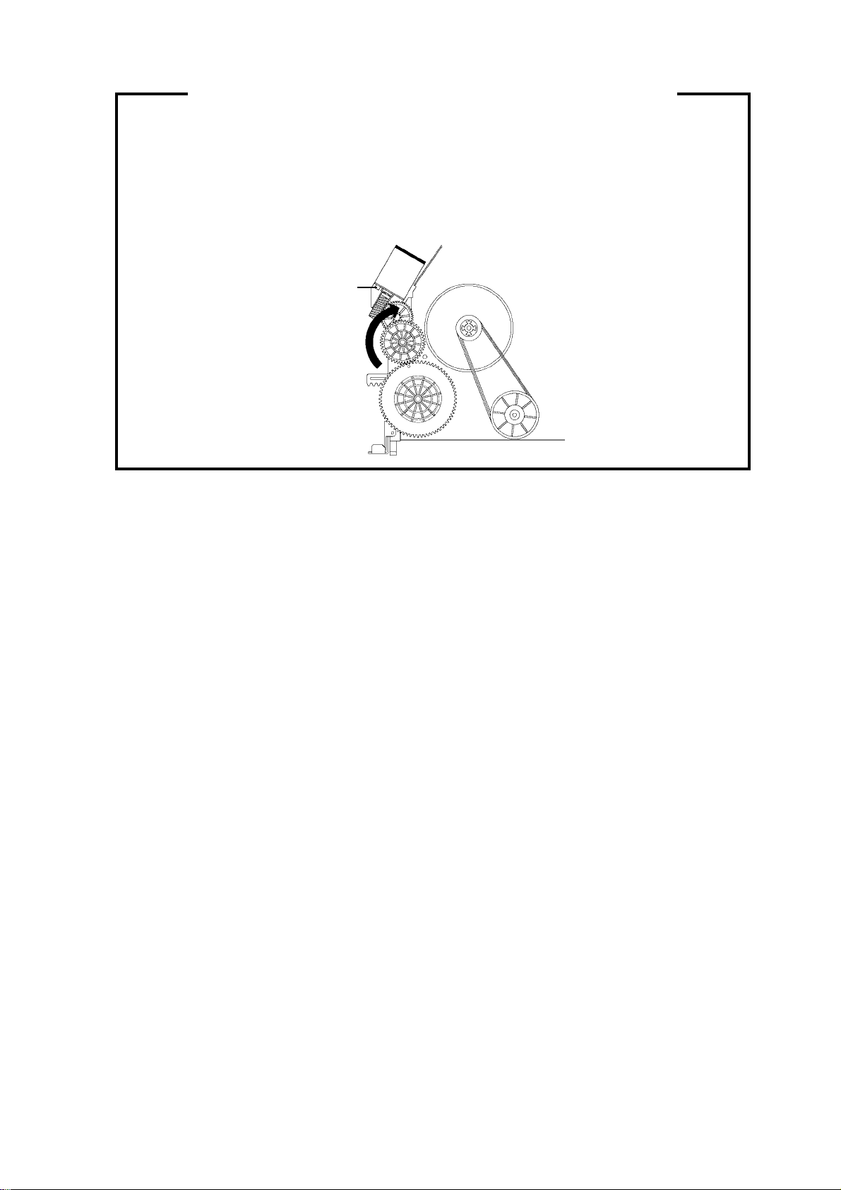
TAPE REMOVAL METHOD AT NO POWER SUPPLY
1.
Remove the VCR block from the main unit.
(Refer to item 1 of the DISASSEMBLY INSTRUCTIONS.)
2.
Remove the screw 1 of the Deck Chassis and remove the Loading Motor.
3.
Rotate the Pinch Roller Cam in the direction of the arrow by hand to slacken the Video Tape.
4.
Rotate the Clutch Ass'y either of the derections to wind the Video Tape in the Cassette Case.
5.
Repeat the above step 3~4. Then take out the Video Cassette from the Deck Chassis. Be careful not to
scratch on the tape.
Loading Motor
Screw 1
Capstan DD Unit
Pinch Roller Cam
Main Cam
Clutch Ass'y
Main Chassis (Front Side)
A1-2

TABLE OF CONTENTS
SERVICING NOTICES ON CHECKING.....................................................................................
HOW TO ORDER PARTS ..........................................................................................................
TAPE REMOVAL METHOD AT NO POWER SUPPLY ............................................................
TABLE OF CONTENTS..............................................................................................................
GENERAL SPECIFICATIONS ...................................................................................................
DISASSEMBLY INSTRUCTIONS
1. REMOVAL OF MECHANICAL PARTS AND P. C. BOARDS............................................
2. REMOVAL OF VCR DECK PARTS ...................................................................................
3. REMOVAL OF ANODE CAP ..............................................................................................
4. REMOVAL AND INSTALLATION OF FLAT PACKAGE IC ...............................................
KEY TO ABBREVIATIONS ........................................................................................................
SERVICE MODE LIST ................................................................................................................
PREVENTIVE CHECKS AND SERVICE INTERVALS..............................................................
WHEN REPLACING EEPROM (MEMORY) IC ..........................................................................
SERVICING FIXTURES AND TOOLS .......................................................................................
PREPARATION FOR SERVICING.............................................................................................
MECHANICAL ADJUSTMENTS ................................................................................................
ELECTRICAL ADJUSTMENTS..................................................................................................
BLOCK DIAGRAMS
TV ............................................................................................................................................
Y/C/AUDIO/HEAD AMP/21PIN/IN/OUT..................................................................................
MICON ....................................................................................................................................
PRINTED CIRCUIT BOARDS
SYSCON/CRT/POWER SW....................................................................................................
POWER ...................................................................................................................................
SCHEMATIC DIAGRAMS
Y/C/AUDIO/HEAD AMP ..........................................................................................................
MICON .....................................................................................................................................
POWER ...................................................................................................................................
21PIN/IN/OUT .........................................................................................................................
CHROMA/IF.............................................................................................................................
SOUND AMP ...........................................................................................................................
T'TEXT/RGB SW.....................................................................................................................
DEFLECTION..........................................................................................................................
CRT..........................................................................................................................................
TV POWER .............................................................................................................................
INTERCONNECTION DIAGRAM ...............................................................................................
WAVEFORMS .............................................................................................................................
MECHANICAL EXPLODED VIEWS...........................................................................................
CHASSIS EXPLODED VIEWS ...................................................................................................
MECHANICAL REPLACEMENT PARTS LIST .........................................................................
CHASSIS REPLACEMENT PARTS LIST..................................................................................
ELECTRICAL REPLACEMENT PARTS LIST...........................................................................
A1-1
A1-1
A1-2
A2-1
A3-1~A3-5
B1-1, B1-2
B2-1~B2-6
B3-1
B4-1, B4-2
C1-1, C1-2
C2-1
C3-1, C3-2
C4-1
D1-1
D1-1
D2-1~D2-4
D3-1~D3-5
E-1, E-2
E-3, E-4
E-5, E-6
F-1~F-4
F-5
G-1, G-2
G-3, G-4
G-5, G-6
G-7, G-8
G-9, G-10
G-11, G-12
G-13, G-14
G-15, G-16
G-17, G-18
G-19, G-20
G-21, G-22
H-1, H-2
I1-1, I1-2
I2-1, I2-2
J1-1
J2-1
J3-1~J3-4
A2-1
GENERAL SPECIFICATIONS
G-1 TV CRT CRT Size / Visual Size 14 inch / 335.4mmV
System CRT Type Normal
Color System PAL
Speaker 1Speaker
Sound Output MAX 1.5 W
G-2 VCR System VHS
System Player / Recorder
Video System PAL
Hi-Fi STEREO No
NTSC PB(PAL 60Hz) Yes
Deck DECK OVD-7
Heads Video Head 2 Head
FM Audio Head No
Audio /Control Mono / Yes
Erase(Full Track Erase) Yes
Tape Rec PAL SP/LP
Speed NTSC -
Play PAL SP/LP
Fast Forward / Rewind Time (Approx.) at 25oC FF:1'48"/REW:1'48"
Forward/Reverse NTSC or PAL-M SP=3x,5x
Picture Search PAL or SECAM SP/LP=5x,7x/7x,13x
Frame Advance No
Slow Speed -
G-3 Tuning Broadcasting System U.K. System I
System Tuner and System 1Tuner
Receive CH Destination U.K.
Intermediate Picture(FP) 39.5MHz
Frequency Sound(FS) 33.5MHz
Preset CH 80CH
Stereo/Dual TV Sound
G-4 Signal Video Signal Input Level 1 V p-p/75 ohm
Audio Signal
Hi-Fi Audio Signal Dynamic Range : More than -
G-5 Power Power Source AC 230~240V 50Hz
Power Consumption at AC 50 W at 230 V 50 Hz
Protector Power Fuse Yes
G-6 Regulation Safety CE , BEAB
G-7 Temperature Operation +5oC ~ +40oC
G-8 Operating Humidity Less than 80% RH
Deflection 90 degree
Magnetic Field BV/BH +0.45G / +0.18G
Position Front
Size 1.5 x 2.5 Inch
Impedance 8 ohm
10%(Typical) 1.0 W
Loading System Front
Motor 3
NTSC SP
Cassette at E-180
Tuning System F-Synth
Input Impedance VHF/UHF 75 ohm
CH Coverage
FP-FS 6.0MHZ
Output Level 1 V p-p/75 ohm
S/N Ratio (Weighted) 53 dB
Horizontal Resolution at SP Mode 240 Lines
Input Level
Output Level
S/N Ratio at SP 42 dB
Harmonic Distortion at SP(1kHz) Typical 1.5 %
Frequency Response at SP 100Hz ~10kHz
at LP 100Hz ~ 5kHz
at SLP -
Frequency Response Wow And Flutter : Less than Channel Separation : More than Harmonic Distortion : Less than -
DC -
at DC Stand by (at AC) 8 W at 230 V 50 Hz
Per Year -
Dew Sensor No
Radiation CE
X-Radiation NONE
Storage -20oC ~ +60oC
21~69
-3.8dBm/50Kohm
-3.8dBm/1Kohm
No
A3-1
GENERAL SPECIFICATIONS
(Symbo
)
G-9 On Screen Menu Yes
Display Menu Type Character
G-CODE(or SHOWVIEW or PLUSCODE)No. Entry
Stereo/Audio Output
Clock/Date Yes
CH/AV Yes
Tape Counter(Linear Counter) Yes
Tape Speed Yes
Sleep Time Yes
Control Volume Yes
Level Bright/Contrast/Sharpness/Color Yes
Auto Tracking/Manual Tracking Yes
S-Repeat/SR-R/SR-PLAY
Index Yes
Mute Yes
Hi-Fi
Repeat Yes
PDC Yes
Zero Return
Dew
G-10 OSD Language English
G-11 Clock,Timer Calendar 1990/1/1 ~ 2081/12/31
and Timer Timer Events 8 prog/ 1 month
Back-up One Touch Recording Max Time SP 5 Hours LP 10Hours
OTPB Valid Time Sleep Timer Max Time 120
On/Off Timer Program(On Timer / Off Timer) 1
Auto Shut Off No Signal 15
Timer Back-up (at Power Off Mode) 30
ATS No
Timer Rec Set Yes
Channel Setup No
TV Setup Yes
VCR Setup
System Setup
Tint
Bass/Treble/Balance
Manual Tracking Yes
Play/Stop/FF/Rew/Rec/OTR/T-Rec/Pause/Eject/Tape In
Auto Tuning No
Ch Mapping
Ch Tuning Yes
Ch Allocation
On/Off Timer Set Yes
Picture Yes
Audio
Auto Repeat On/Off Yes
System Select
Scene Repeat
Clock Set Yes (Calendar 24h)
Language
Bilingual
NICAM
l Mark
Step 10
No Operation -
Yes
No
No
No
No
No
No
No
No
No
No
No
No
No
No
No
No
No
No
min.
min.
prog.
min.
min.
min.
A3-2
GENERAL SPECIFICATIONS
G-12 Remote Unit RC-DM
Control Glow in Dark Remocon Yes
Power Source Voltage(D.C) 3V
UM size x pcs UM-4 x 2 pcs
Total Keys 38
Keys Power Yes
1 Yes
2 Yes
3 Yes
4 Yes
5 Yes
6 Yes
7 Yes
8 Yes
9 Yes
0/AV Yes
CH/Tr Up Yes
CH/Tr Up/Page Up
CH/Tr Down Yes
CH/Tr Down /Page Down
Volume Up Yes
Volume Down Yes
Play/Up Yes
Play/Up/Slow
F.Fwd/Right Yes
Rew/Left Yes
Pause/Still Yes
Pause
Stop/Down Yes
Rec/OTR Yes (2Keys)
Eject Yes
Counter Reset Yes
Speed Yes
Timer Rec Yes (2Keys)
TV Monitor Yes
TV Monitor /Rec Monitor
Program Yes
Program /V+
Auto Tracking Yes
Auto Tracking /Reveal
Menu Yes
Enter Yes
Enter/Hold
Cancel/Ch Skip Yes
Cancel/Ch Skip/F-T-B
Index Yes
Index /Sub Page (Time Text)
Call Yes
Text/Mix/TV
Sleep Timer Yes
Mute Yes
Zero Return Yes
Red
Cyan
Green
Yellow
Audio Select
Keys
No
No
No
No
No
No
No
No
No
No
No
No
No
No
No
No
A3-3
GENERAL SPECIFICATIONS
G-13 Features Auto Head Cleaning
Auto Tracking Yes
HQ (VHS Standard High Quality) Yes
Auto Power On, Auto Play, Auto Rewind, Auto Eject Yes
Auto Shut Off Yes
Auto Repeat Yes
VIDEO PLUS+(SHOWVIEW,G-CODE)
CH Auto Set-Up/Auto Clock Yes
PDC Yes
Forward / Reverse Picture Search Yes
One Touch Playback
Auto Tuning
Anti-Theft
End Call
Index Search Yes
SQPB
CATV
CM Skip(30sec x 6 Times)
Comb Filter
T'Text
Text type Scene Repeat
Hotel Lock
TV Monitor Yes
Power On Memory
Protect of FBT Leak Circuit Yes
Choke Coil
G-14 Accessories Owner's Manual Language English
w/Guarantee Card
Remote Control Unit Yes
Rod Antenna
Poles -
Terminal -
w/300 ohm to 75 ohm Antenna Adapter -
Loop Antenna Yes
Terminal DIN Type
U/V Mixer
DC Car Cord (Center+)
Guarantee Card
Warning Sheet
Circuit Diagram
Antenna Change Plug
Service Facility List
Important Safeguard
Dew/AHC Caution Sheet
AC Plug Adapter
Quick Set-up Sheet Yes
Battery Yes
UM size x pcs UM-4 x 2 pcs
OEM Brand
AC Cord
AV Cord (2Pin-1Pin)
21pin-RCA Cable
RF Cable Yes (0.9m)
Registration Card Yes
PTB Sheet
Anti-Theft Sheet
Euro Warranty Information Sheet
Helpline Sheet Yes[From 2nd Lot]
No
No
No
No
No
No
No
No
No
No
No
No
No
No
No
No
No
No
No
No
No
No
No
No
No
No
No
No
No
No
No
No
No
No
A3-4
GENERAL SPECIFICATIONS
G-15 Interface Switch Front Power Yes
Rear Main Power SW
Indicator Standby Yes(Red)
Key Light up Rec/OTR
Terminals Front Video Input Yes
Rear Video Input
G-16 Set Size Approx. W x D x H (mm) 362 x 365 x 382
G-17 Weight Net (Approx.) 11.0 kg
G-18 Carton Master Carton
Gift Box Yes
Drop Test Natural Dropping At
Container Stuffing(40' container) 700
G-19 Material Cabinet Front PS 94HB
PCB Non-Halogen Demand Yes
Play Yes
Pause/Still
System Select
One Touch Playback
Input Select
Channel Up Yes
Channel Down Yes
F.FWD/Cue Yes
Eject/Stop Yes
Main Power SW Yes
Volume Up Yes
Volume Down Yes
Rew/Rev Yes
Rec/OTR Yes
Rec/OTR Yes(Red)
T-Rec Yes(Red)
On Timer
CS
One Touch Playback
Play
Audio Input Yes
Other Terminal Head Phone(Stereo & Mono, 3.5mm)
Audio Input
Video Output
Audio Output
Euro Scart 1-SCART
Diversity
Ext Speaker
DC Jack 12V(Center +)
VHF/UHF Antenna Input
AC Inlet
Gross (Approx.) 12.5 kg
Content -
Material -
Dimensions W x D x H(mm) -
Description of Origin -
Material Double/White
Dimensions W x D x H(mm) 423 x 447 x 443
Design As per Buyer's
Description of Origin Yes
Height (cm) 62
Rear PS 94V0/Non-Decabrom
Jack Panel PS 94V2 or More /Non-Harogen
Eyelet Demand Yes
DIN type
1 Corner / 3 Edges / 6 Surfaces
No
No
No
No
No
No
No
No
No
No
No
No
No
No
No
No
No
No
( - lbs)
( - lbs)
No
Sets
A3-5
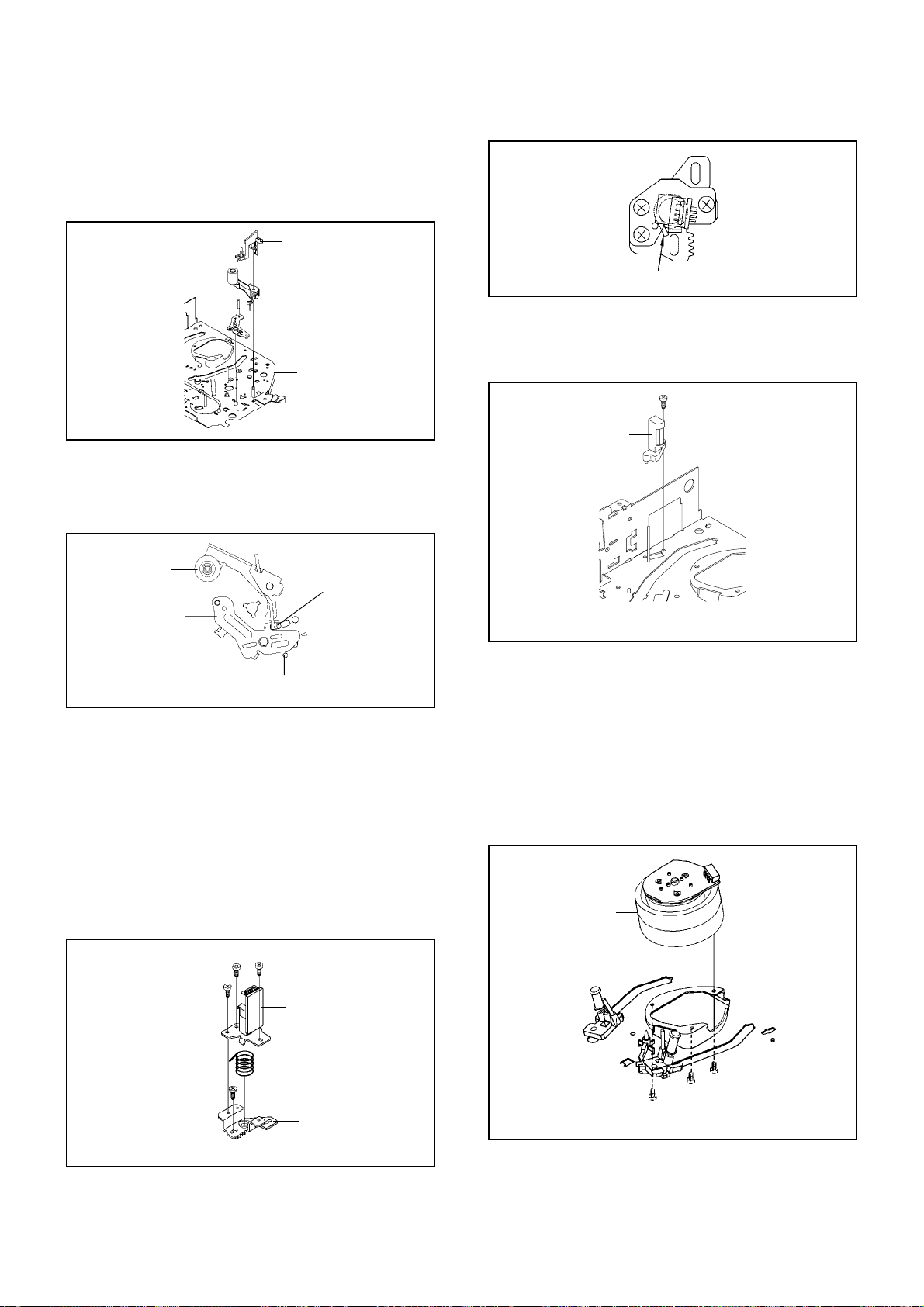
DISASSEMBLY INSTRUCTIONS
1. REMOVAL OF MECHANICAL PARTS
AND P.C. BOARDS
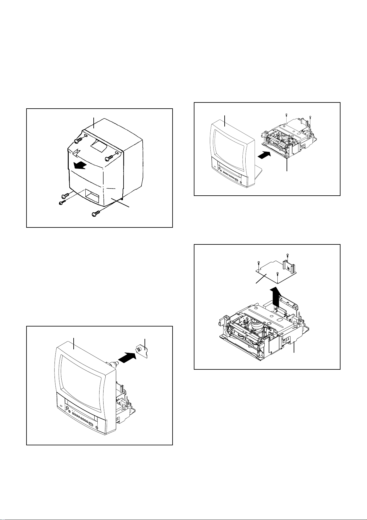
1-1: BACK CABINET (Refer to Fig. 1-1)
1.
Remove the 5 screws 1.
2.
Remove the AC cord from the AC cord hook 2.
3.
Remove the Back Cabinet in the direction of arrow.
Front Cabinet
1
1
1
1
1-2: CRT PCB (Refer to Fig. 1-2)
CAUTION: BEFORE REMOVING THE ANODE CAP,
DISCHARGE ELECTRICITY BECAUSE IT
CONTAINS HIGH VOLTAGE.
BEFORE ATTEMPTING TO REMOVE OR
REPAIR ANY PCB, UNPLUG THE POWER
CORD FROM THE AC SOURCE.
1.
Remove the Anode Cap.
(Refer to REMOVAL OF ANODE CAP)
2.
Disconnect the following connector:
(CP801).
3.
Remove the CRT PCB in the direction of arrow.
2
Back Cabinet
1
Fig. 1-1
1-3: TV/VCR BLOCK (Refer to Fig. 1-3)
1.
Remove the 2 screws 1.
2.
Disconnect the following connectors:
(CP302, CP402, CP501 and CP502).
3.
Unlock the support 2.
4.
Remove the TV/VCR Block in the direction of arrow.
Front Cabinet
1
TV/VCR Block
1
2
UP TO
RELEASE
1-4: POWER PCB (Refer to Fig. 1-4)
1.
Remove the 3 screws 1.
2.
Disconnect the following connectors:
(CP401A and CP851A).
3.
Remove the Power PCB in the direction of arrow.
1
1
1
Power PCB
Fig. 1-3
Front Cabinet
CRT PCB
TV/VCR Block
Fig. 1-4
Fig. 1-2
B1-1
DISASSEMBLY INSTRUCTIONS
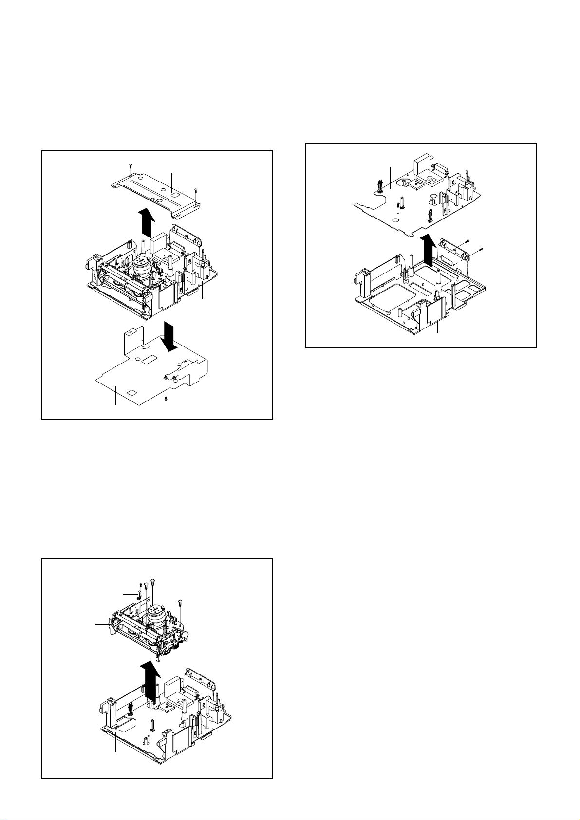
1-5: DECK SHIELD PLATE (Refer to Fig. 1-5)
1.
Remove the 2 screws 1.
2.
Remove the Deck Shield Plate in the direction of arrow (A).
3.
Remove the screw 2.
4.
Remove the Bottom Shield Plate in the direction of arrow (B).
1
Deck Shield Plate
1
(A)
TV/VCR Block
(B)
1-7: JACK PLATE AND SYSCON PCB (Refer to Fig. 1-7)
1.
Remove the screw 1.
2.
Remove the 2 screws 2.
3.
Remove the Syscon PCB in the direction of arrow.
Syscon PCB
1
2
2
Deck Holder
Fig. 1-7
Bottom Shield Plate
2
Fig. 1-5
1-6: DECK CHASSIS (Refer to Fig. 1-6)
NOTE
Do not remove the cable at the FE Head section. The FE
Head may be damaged if you remove the cable by force.
1.
Remove the screw 1.
2.
Remove the FE Head.
3.
Remove the 3 screws 2.
4.
Disconnect the following connectors:
(CP1001, CP4001, CP4004 and CP4005).
5.
Remove the Deck Chassis in the direction of arrow.
2
2
1
FE Head
Deck Chassis
2
Syscon PCB
Fig. 1-6
B1-2
DISASSEMBLY INSTRUCTIONS
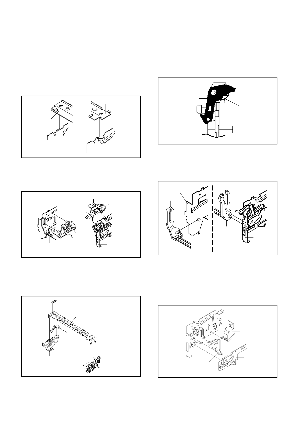
2. REMOVAL OF VCR DECK PARTS
2-1: TOP BRACKET (Refer to Fig. 2-1)
Extend the 2 supports 1.
1.
Slide the 2 supports 2 and remove the Top Bracket.
2.
NOTE
After the installation of the Top Bracket, bend the
1.
support 1 so that the Top Bracket is fixed.
Top Bracket
1
Top Bracket
2
Main Chassis
2
Main Chassis
2-2: CASSETTE HOLDER ASS'Y (Refer to Fig. 2-2)
1.
Move the Cassette Holder Ass'y to the front side.
2.
Push the Locker R to remove the Cassette Side R.
3.
Remove the Cassette Side L.
Cassette Side R
Main Chassis
1
Fig. 2-1
Locker R
NOTE
1.2.In case of the Locker R installation, check if the one
position of Fig.2-3-B are correctly locked.
When you install the Cassette Side R, be sure to move
the Locker R after installing.
Locker R
Check if this position
Cassette Side R
is locked.
Fig. 2-3-B
2-4: LINK UNIT (Refer to Fig. 2-4)
1.
Set the Link Unit to the Eject position.
2.
Unlock the support 1.
3.
Remove the (A) side of the Link Unit first, then remove
the (B) side.
Main Chassis
Link Unit
Link Unit
Cassette Side L
Main Chassis
Fig. 2-2
2-3: CASSETTE SIDE L/R (Refer to Fig. 2-3-A)
1.
Remove the Locker Spring.
2.
Unlock the 4 supports 1 and then remove the Cassette
Side L/R.
3.
Unlock the support 2 and then remove the Locker R.
Locker Spring
1
1
2
Cassette Side R
Cassette Holder
Locker R
1
1
Cassette Side L
(A)
(B)
Link Unit
2-5: LINK LEVER/FLAP LEVER/BOT COVER
(Refer to Fig. 2-5)
Unlock the support 1.
1.
Remove the BOT Cover.
2.
Extend the support 2.
3.
Remove the Link Lever.
4.
Remove the Flap Lever.
5.
1
2
Flap Lever
BOT Cover
Link Lever
Main Chassis
Fig. 2-4
Fig. 2-3-A
Fig. 2-5
B2-1
DISASSEMBLY INSTRUCTIONS
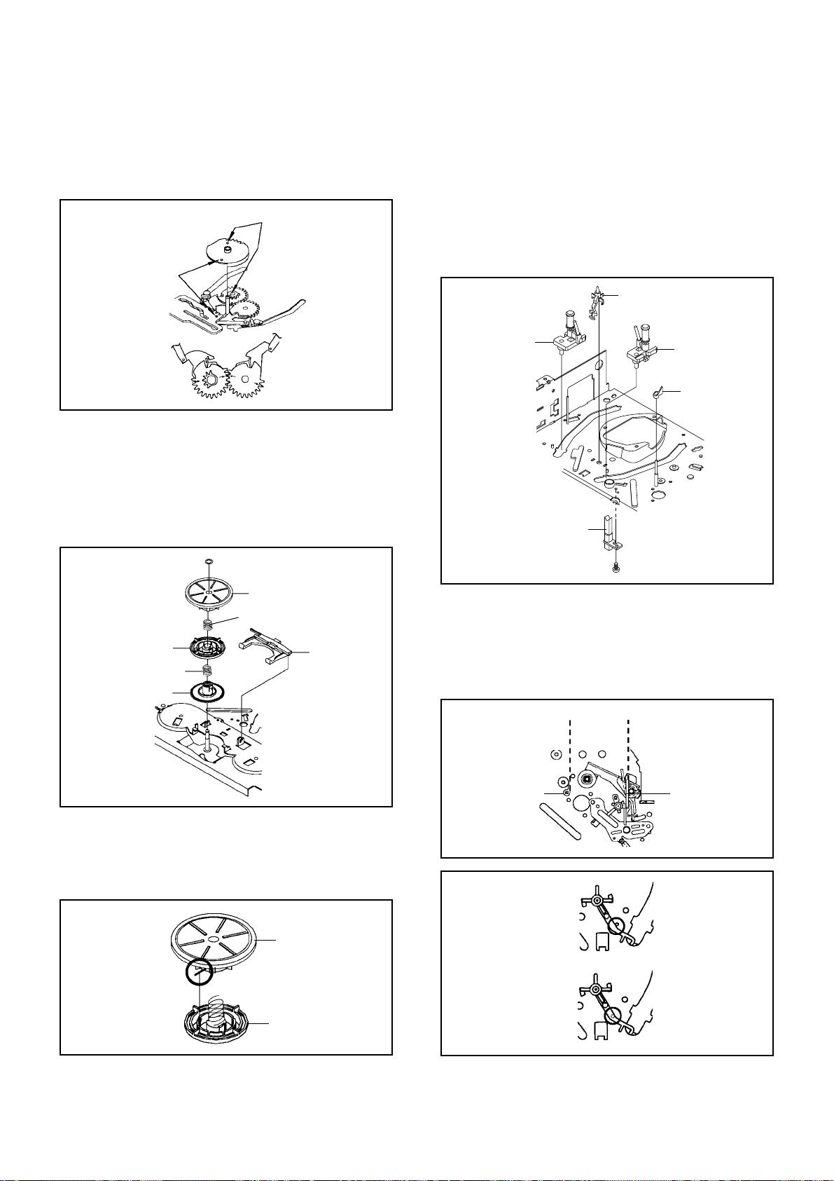
2-6: LOADING MOTOR/WORM (Refer to Fig. 2-6-A)
1.
Remove the screw 1.
2.
Remove the Loading Motor.
3.
Remove the Worm.
Loading Motor
Worm
Main Chassis
• Screw Torque: 3 ± 0.5kgf•cm
1
Fig. 2-6-A
NOTE
1.
In case of the Worm installation, check if the value of
the Fig. 2-6-B is correct.
2.
In case of the Loading Motor installation, hook the wire
on the Cassette Opener as shown Fig. 2-6-C.
3.
When installing the wires between Capstan DD Unit
and Loading Motor, connect them correctly as shown
Fig. 2-6-D.
19.2 ± 0.1mm
2-7: TENSION ASS’Y (Refer to Fig. 2-7-B)
1.
Turn the Pinch Roller Cam clockwise so that the Tension
Holder hook is set to the position of Fig. 2-7-A to move
the Tension Arm Ass’y.
2.
Remove the Tension Spring.
3.
Unlock the 2 supports 1 and remove the Tension Band.
4.
Unlock the support 2 and remove the Tension Arm Ass’y.
5.
Unlock the support 3 and remove the Tension Connect.
6.
Float the hook 4 and turn it clockwise then remove the
Tension Holder.
T ension Arm Ass’y
Fig. 2-7-A
1
Tension Connect
Tension Spring
2
4
1
3
Tension Holder
Tension Band
Tension Arm Ass’y
Loading Motor
-
+
Safety surface for pressing
of the insert.
Pink
White
Fig. 2-6-B
Loading Motor
Cassette Opener
Fig. 2-6-C
Capstan DD Unit
L2
L1
Fig. 2-6-D
Fig. 2-7-B
NOTE
1.
In case of the Tension Band installation, note the
direction of the installation. (Refer to Fig. 2-7-C)
2.
In case of the Tension Band installation, install correctly
as Fig. 2-7-D.
3.
In case of the Tension Connect installation, install as
the circled section of Fig. 2-7-E.
Tension Connect
Tension Band
Fig. 2-7-C
B2-2
[OK]
[NG]
Tension Connect
Tension Connect
Tension Connect
DISASSEMBLY INSTRUCTIONS
NOTE
1.
Take care not to damage the gears of the S Reel and T
Tension Band
Tension Band
Fig. 2-7-D
Reel.
2.
The Polyslider Washer may be remained on the back of
the reel.
3.
Take care not to damage the shaft.
4.
Do not touch the section “A” of S Reel and T Reel. (Use
gloves.) (Refer to Fig. 2-9-A) Do not adhere the stains
on it.
5.
When you install the reel, clean the shaft and grease it.
(If you do not grease, noise may be heard in FF/REW
mode.)
6.
After installing the reel, adjust the height of the reel.
(Refer to MECHANICAL ADJUSTMENT)
Main Chassis
Fig. 2-7-E
2-8: T BRAKE ARM/T BRAKE BAND (Refer to Fig. 2-8-A)
Remove the T Brake Spring.
1.
Turn the T Brake Arm clockwise and bend the hook
2.
section to remove it.
Unlock the 2 supports 1 and remove the T Brake Band.
3.
T Brake Band
Hook section
1
1
T Brake Arm
T Brake Spring
Fig. 2-8-A
NOTE
1. In case of the T Brake Band installation, install correctly
as Fig. 2-8-B.
Idler Gear
Idler Arm Ass’y
S Reel
(A)
(B)
T Reel
1
(A)
1
Fig. 2-9-A
NOTE
1.2.In case of the S Reel and T Reel installation, check if
the correct parts are installed. (Refer to Fig. 2-9-B)
In case of the Idler Arm Ass’y installation, install correctly as Fig. 2-9-C. And also set it so that the section
“B” of Fig. 2-9-A is placed under the Main Chassis tab.
[OK]
T Brake Band
[NG]
T Brake Band
T Brake Arm
T Brake Arm
Fig. 2-8-B
2-9: S REEL/T REEL/IDLER ARM ASS’Y/IDLER GEAR
(Refer to Fig. 2-9-A)
1.
Remove the S Reel and T Reel.
2.
Remove the 2 Polyslider Washers 1.
3.
Remove the Idler Arm Ass’y and Idler Gear.
B2-3
[OK]
[NG]
Clutch Gear
Clutch Gear
Big Hole
(S Reel)
Small Hole
(T Reel)
Fig. 2-9-B
Idler Arm Ass’y
Idler Arm Ass’y
Fig. 2-9-C
DISASSEMBLY INSTRUCTIONS
2-10: CASSETTE OPENER/PINCH ROLLER BLOCK/P5
ARM ASS’Y (Refer to Fig. 2-10-A)
1.2.Unlock the support 1 and remove the Cassette Opener.
Remove the Pinch Roller Block and P5 Arm Ass’y.
1
Cassette Opener
Pinch Roller Block
P5 Arm Ass’y
Main Chassis
Fig. 2-10-A
NOTE
1.2.Do not touch the Pinch Roller. (Use gloves.)
In case of the Pinch Roller Block and the Pinch Roller
Cam installation, install correctly as Fig. 2-10-B.
Pinch Roller Block
P5 Arm Ass’y
Can be seen the hole of the
Main Cam.
Can be seen the hole of
the Pinch Roller Cam.
Fig. 2-10-B
2-11: A/C HEAD (Refer to Fig. 2-11-A)
1.
Remove the screw 1.
2.
Remove the A/C Head Base.
3.
Remove the 3 screws 2.
4.
Remove the A/C Head and A/C Head Spring.
NOTE
1.
Do not touch the A/C Head. (Use gloves.)
2.
When you install the A/C Head Spring, install as shown in
Fig. 2-11-B.
3.
When you install the A/C Head, tighten the screw (1) first,
then tighten the screw (2), finally tighten the screw (3).
Spring Position
Fig. 2-11-B
2-12: FE HEAD (RECORDER ONLY) (Refer to Fig. 2-12)
Remove the screw 1.
1.
Remove the FE Head.
2.
1
FE Head
• Screw Torque: 5 ± 0.5kgf•cm
• The FE Head is not installed on the Video Cassette Player.
Fig. 2-12
2-13: CYLINDER UNIT ASS'Y (Refer to Fig. 2-13)
Disconnect the following connector:
1.
(CD2001)
Remove the 3 screws 1.
2.
Remove the Cylinder Unit Ass'y.
3.
NOTE
1.
When you install the Cylinder Unit Ass'y, tighten the
screws from (1) to (3) in order while pulling the Ass'y
toward the left front direction.
Cylinder Unit Ass'y
(1)
2
2
(2)
1
• Screw Torque: 5 ± 0.5kgf•cm (Screw 1)
(3)
2
A/C Head
A/C Head Spring
A/C Head Base
Fig. 2-11-A
B2-4
• Screw Torque: 3 ± 0.5kgf•cm
(3)
(2)
(1)
1
1
1
Fig. 2-13
DISASSEMBLY INSTRUCTIONS
2-14: CAPSTAN DD UNIT (Refer to Fig. 2-14-A)
1.
Remove the Capstan Belt.
2.
Remove the 3 screws 1.
3.
Remove the Capstan DD Unit.
Capstan Belt
Capstan DD Unit
1
1
1
• Screw Torque: 4 ± 0.5kgf•cm
Fig. 2-14-A
NOTE
1. In case of the Capstan DD Unit installation, apply the
silicon bond (TSE3843-W) on the position Fig. 2-14-B
correctly. (If no silicon bond applied, abnormal noise
will be heard on the deck operation.)
(Refer to Fig. 2-14-B, C)
Applied position of
silicon bond
2-15: MAIN CAM/PINCH ROLLER CAM/JOINT GEAR
(Refer to Fig. 2-15-A)
1.2.Remove the E-Ring 1, then remove the Main Cam.
Remove the E-Ring 2, then remove the Pinch Roller
Cam and Joint Gear.
1
Main Cam
2
Pinch Roller Cam
Joint Gear
Fig. 2-15-A
NOTE
1. In case of the Pinch Roller Cam and Main Cam installation, install them as the circled section of Fig. 2-15-B so
that the each markers are met. (Refer to Fig. 2-15-B)
And also can be seen the Main Chassis hole through
the Main Cam maker hole.
Pinch Roller Cam
Marker
Main Cam
Capstan DD Unit
Be careful not to apply the silicon
bond to the Pinch Roller.
Fig. 2-14-B
Silicon Bond
Main Chassis
Fig. 2-14-C
Fig. 2-15-B
2-16: LOADING GEAR S/T UNIT (Refer to Fig. 2-16-A)
1.2.Remove the E-Ring 1 and remove the Main Loading
Gear.
Remove the Main Rod, Tension Lever, Loading Arm S
Unit and Loading Arm T Unit.
1
Main Rod
Tension Lever
Main Loading Gear
Loading Arm T Unit
Loading Arm S Unit
Fig. 2-16-A
B2-5
DISASSEMBLY INSTRUCTIONS
NOTE
1. When you install the Loading Arm S Unit, Loading Arm
T Unit and Main Loading Gear, align each marker.
(Refer to Fig. 2-16-B)
Marker
Main Loading Gear
Marker
Loading Arm T Unit Loading Arm S Unit
Fig. 2-16-B
2-17: CLUTCH ASS’Y/RING SPRING/CLUTCH LEVER/
CLUTCH GEAR (Refer to Fig. 2-17-A)
1.
Remove the Polyslider Washer 1.
2.
Remove the Clutch Ass’y and Ring Spring.
3.
Remove the Clutch Lever.
4.
Remove the Coupling Gear, Coupling Spring and
Clutch Gear.
2-18:
CASSETTE GUIDE POST/INCLINED BASE S/T
UNIT/P4 CAP/LED REFLECTOR
(Refer to Fig. 2-18-A)
Remove the P4 Cap.
1.
Unlock the support 1 and remove the Cassette Guide
2.
Post.
Remove the Inclined Base S/T Unit.
3.
Remove the screw 2.
4.
Remove the LED Reflector.
5.
1
Inclined Base S Unit
LED Reflector
Cassette Guide Post
Inclined Base T Unit
P4 Cap
1
Clutch Ass’y
Ring Spring
Coupling Gear
Coupling Spring
Clutch Gear
Clutch Lever
Fig. 2-17-A
NOTE
1. In case of the Clutch Ass’y installation, install it with
inserting the spring of the Clutch Ass’y into the dent of
the Coupling Gear. (Refer to Fig. 2-17-B)
Clutch Ass’y
• Screw Torque: 5 ± 0.5kgf•cm
2
Fig. 2-18-A
NOTE
1.
Do not touch the roller of Guide Roller.
2.
In case of the P4 Cap installation, install it with parallel
for “A” and “B” of Fig. 2-18-B.
3.
In case of the Cassette Guide Post installation, install
correctly as the circled section of Fig. 2-18-C.
“A”
P4 Cap
“B”
Cassette Opener
Fig. 2-18-B
[OK]
Cassette Guide Post
Coupling Gear
Fig. 2-17-B
[NG]
Cassette Guide Post
Fig. 2-18-C
B2-6
DISASSEMBLY INSTRUCTIONS
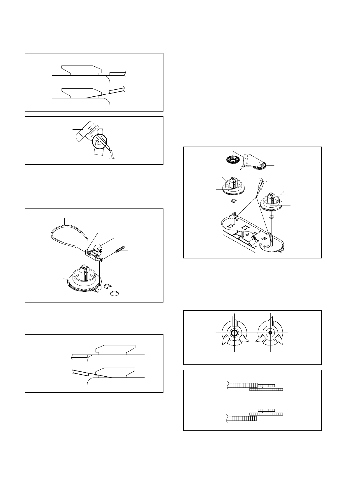
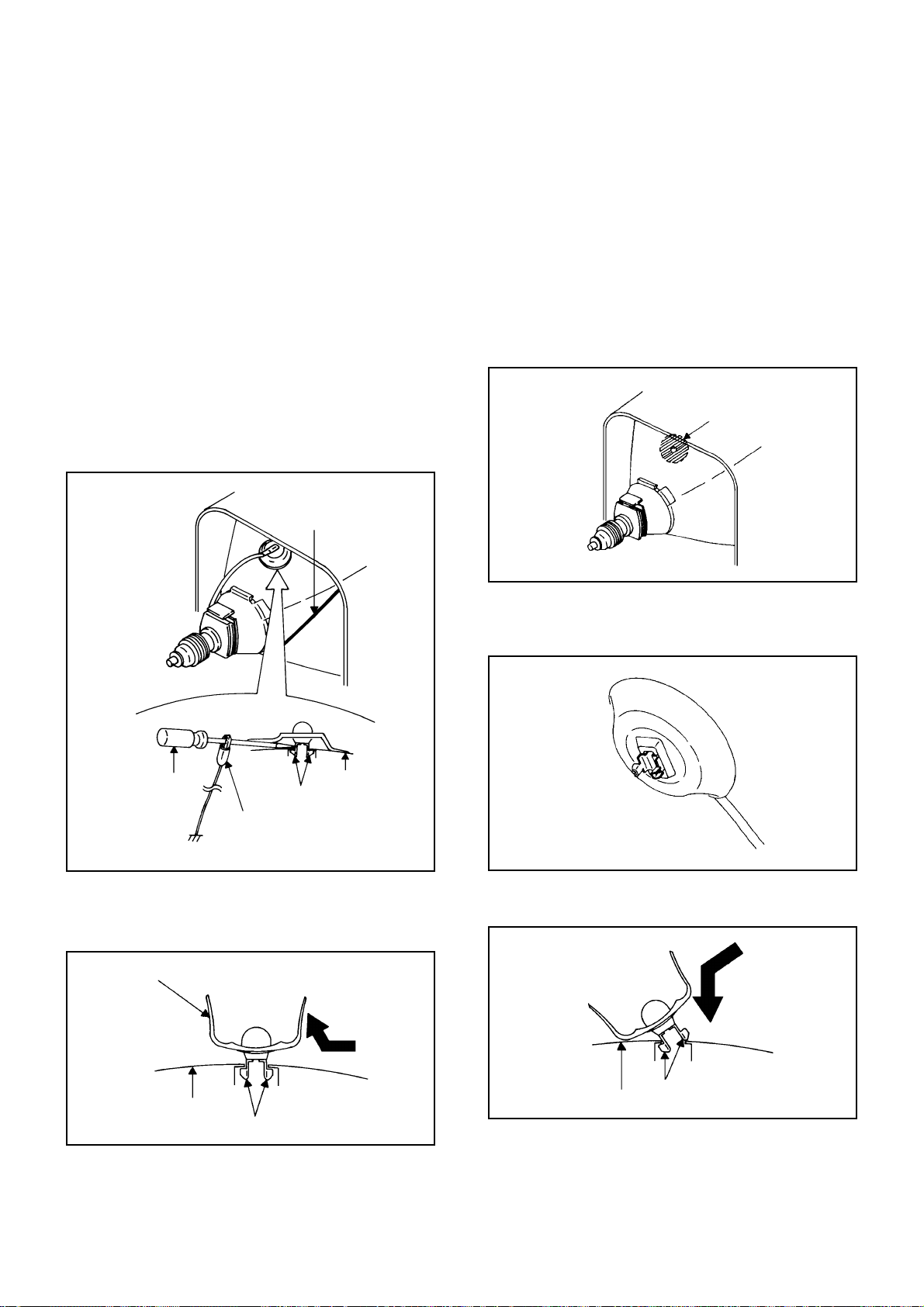
3. REMOVAL OF ANODE CAP
Read the following NOTED items before starting work.
After turning the power off there might still be a potential
*
voltage that is very dangerous. When removing the
Anode Cap, make sure to discharge the Anode Cap's
potential voltage.
*
Do not use pliers to loosen or tighten the Anode Cap
terminal, this may cause the spring to be damaged.
REMOVAL
1. Follow the steps as follows to discharge the Anode Cap.
(Refer to Fig. 3-1.)
Connect one end of an Alligator Clip to the metal part of a
flat-blade screwdriver and the other end to ground.
While holding the plastic part of the insulated Screwdriver,
touch the support of the Anode with the tip of the
Screwdriver.
A cracking noise will be heard as the voltage is discharged.
GND on the CRT
3. After one side is removed, pull in the opposite direction
to remove the other.
NOTE
Take care not to damage the Rubber Cap.
INSTALLATION
1. Clean the spot where the cap was located with a small
amount of alcohol. (Refer to Fig. 3-3.)
NOTE
Confirm that there is no dirt, dust, etc. at the spot where
the cap was located.
Location of Anode Cap
Fig. 3-3
Screwdriver
Alligator Clip
GND on the CRT
Flip up the sides of the Rubber Cap in the direction of
2.
the arrow and remove one side of the support.
(Refer to Fig. 3-2.)
Rubber Cap
Support
CRT
Fig. 3-1
2.3.Arrange the wire of the Anode Cap and make sure the
wire is not twisted.
Turn over the Rubber Cap. (Refer to Fig. 3-4.)
Fig. 3-4
4. Insert one end of the Anode Support into the anode
button, then the other as shown in Fig. 3-5.
CRT
Support
Fig. 3-2
Support
CRT
5.6.Confirm that the Support is securely connected.
Put on the Rubber Cap without moving any parts.
B3-1
Fig. 3-5
DISASSEMBLY INSTRUCTIONS
4.
REMOVAL AND INSTALLATION OF
FLAT PACKAGE IC
REMOVAL
Put the Masking Tape (cotton tape) around the Flat
1.
Package IC to protect other parts from any damage.
(Refer to Fig. 4-1.)
NOTE
Masking is carried out on all the parts located within
10 mm distance from IC leads.
When IC starts moving back and forth easily after
3.
desoldering completely, pickup the corner of the IC using
a tweezers and remove the IC by moving with the IC
desoldering machine. (Refer to Fig. 4-3.)
NOTE
Some ICs on the PCB are affixed with glue, so be
careful not to break or damage the foil of each IC
leads or solder lands under the IC when removing it.
Blower type IC
desoldering
machine
Masking Tape
(Cotton Tape)
Heat the IC leads using a blower type IC desoldering
2.
IC
machine. (Refer to Fig. 4-2.)
NOTE
Do not add the rotating and the back and forth
directions force on the IC, until IC can move back and
forth easily after desoldering the IC leads completely.
Blower type IC
desoldering machine
Fig. 4-1
Tweezers
IC
Peel off the Masking Tape.4.
Absorb the solder left on the pattern using the Braided
5.
Shield Wire. (Refer to Fig. 4-4.)
NOTE
Do not move the Braided Shield Wire in the vertical
direction towards the IC pattern.
Fig. 4-3
Braided Shield Wire
Soldering Iron
IC
Fig. 4-2
IC pattern
Fig. 4-4
B4-1
DISASSEMBLY INSTRUCTIONS
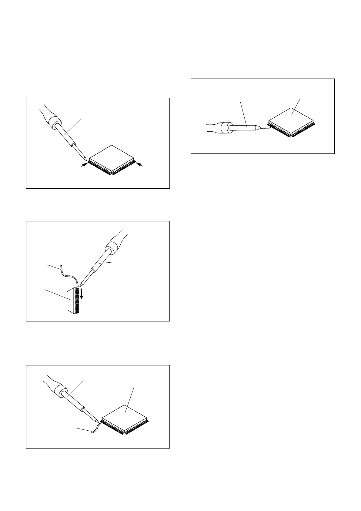
INSTALLATION
Take care of the polarity of new IC and then install the
1.
new IC fitting on the printed circuit pattern. Then solder
each lead on the diagonal positions of IC temporarily.
(Refer to Fig. 4-5.)
Soldering Iron
Solder temporarily
Supply the solder from the upper position of IC leads
2.
Solder temporarily
sliding to the lower position of the IC leads.
(Refer to Fig. 4-6.)
Fig. 4-5
When bridge-soldering between terminals and/or the
4.
soldering amount are not enough, resolder using a Thintip Soldering Iron. (Refer to Fig. 4-8.)
Thin-tip Soldering Iron
IC
Fig. 4-8
Finally, confirm the soldering status on four sides of the
5.
IC using a magnifying glass.
Confirm that no abnormality is found on the soldering
position and installation position of the parts around the
IC. If some abnormality is found, correct by resoldering.
NOTE
When the IC leads are bent during soldering and/or
repairing, do not repair the bending of leads. If the
bending of leads are repaired, the pattern may be
damaged. So, be always sure to replace the IC in this
case.
Soldering IronSolder
IC
Absorb the solder left on the lead using the Braided
3.
Supply soldering
from upper position
to lower position
Shield Wire. (Refer to Fig. 4-7.)
NOTE
Do not absorb the solder to excess.
Soldering Iron
IC
Braided Shield Wire
Fig. 4-6
Fig. 4-7
B4-2
 Loading...