

Page 1

Page 2
Page 3

Page 4

Page 5

Page 6

Contents
Chapter 1: Introduction ...............................................................................................................8
Features ........................................................................................................................................8
Contents ......................................................................................................................................10
Parts Name and Functions .......................................................................................................... 11
Buttons, Switch, and Indicator ............................................................................................11
Connectors and Terminals ................................................................................................... 12
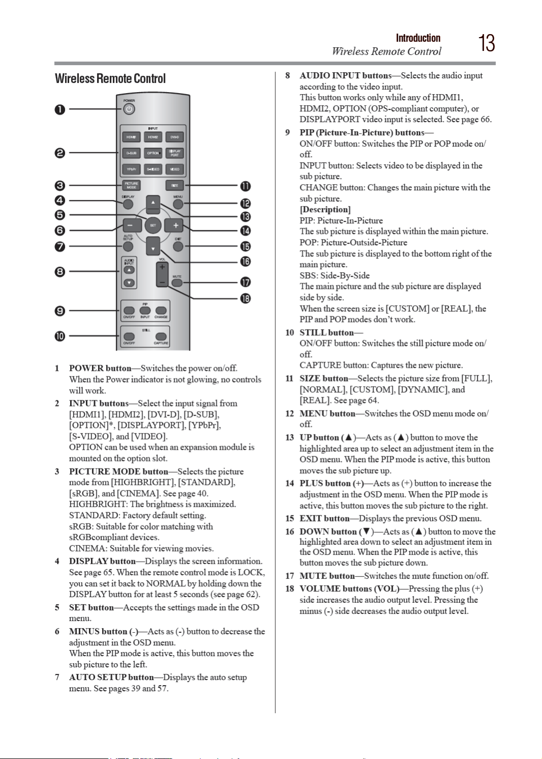
Wireless Remote Control
How to Use the Wireless Remote Control ............................................................................14
Chapter 2: Preparation for use ..................................................................................................15
Preparation for installation ..........................................................................................................15
Determine the installation location ......................................................................................15
Ventilation requirements for enclosure mounting ................................................................ 15
Using the wall mount or ceiling mount.................................................................................16
Installing the monitor .................................................................................................................17
Using the wall mount spacers ..............................................................................................17
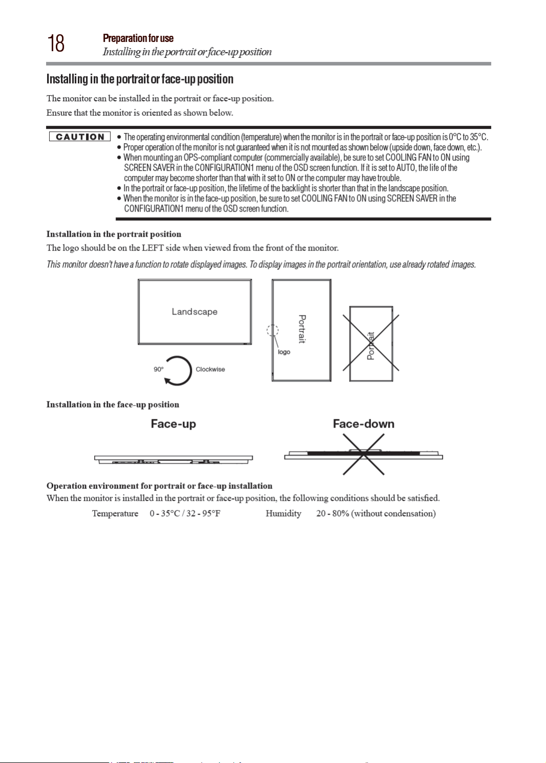
Installing in the portrait or face-up position .........................................................................18
Attaching the corner protectors ...........................................................................................18
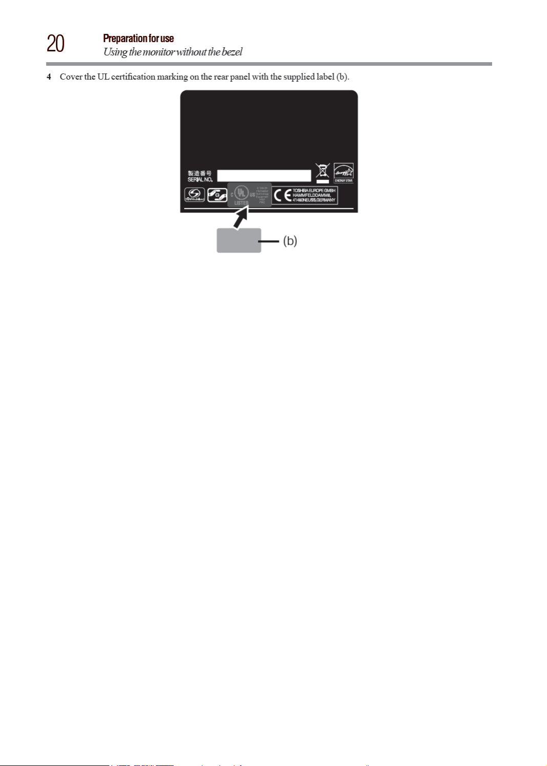
Using the monitor without the bezel ............................................................................................19
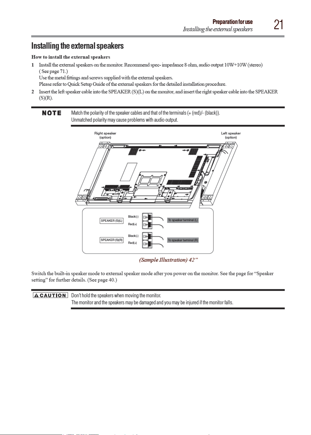
Installing the external speakers ...................................................................................................21
Connection procedure ................................................................................................................. 22
Wiring diagram ...................................................................................................................22
Prevention of disconnection of HDMI cable .........................................................................23
Connecting with a computer (analog connection) ................................................................ 24
Connecting with a computer (digital connection) .................................................................25
Connecting a video device (component video/HDMI device) ................................................26
Connecting a video device (composite video/ S video device)/stereo amplifier ....................27
Installing the expansion module .................................................................................................28
Installation of the expansion module ...................................................................................28
Connecting OPS-compliant computer .................................................................................28
Mounting the OPS-compliant computer on the monitor ......................................................29
Connecting RS-232C .................................................................................................................. 30
Monitor control via RS-232C ...............................................................................................30
Connecting LAN .........................................................................................................................31
Monitor connection using LAN ............................................................................................ 31
Connecting a USB device .............................................................................................................32
Connecting multiple USB devices using the USB hub function .............................................32
Connecting the power cord to the monitor ...................................................................................33
Connecting the power source ..............................................................................................33
..........................................................................................13
Chapter 3: How to Use ..............................................................................................................34
Turning on all the connected devices ...........................................................................................34
Turning on the monitor .......................................................................................................34
Power Management Function .............................................................................................. 35
Selecting the video input .............................................................................................................36
Controlling the external devices ...................................................................................................37
Selecting the OSD language ........................................................................................................37
Auto-setup (analog inputs only) ..................................................................................................38
Selecting the picture mode .......................................................................................................... 39
Screen adjustment ......................................................................................................................39
Picture adjustment ...................................................................................................................... 40
6
Page 7

Contents
Speaker setting ...........................................................................................................................40
Volume, balance, and tone control .............................................................................................. 40
Schedule setting ......................................................................................................................... 41
How to set up schedule .......................................................................................................42
Remote control ...........................................................................................................................43
RS-232C Remote control ....................................................................................................43
LAN Remote control ........................................................................................................... 45
Setting the USB hub ...................................................................................................................46
Configuration and basic operation of OSD screen ........................................................................47
Configuration of OSD screen ............................................................................................... 47
Basic operation of OSD screen ............................................................................................48
Picture ................................................................................................................................49
Screen .................................................................................................................................52
Audio
..................................................................................................................................54
PIP ( Picture In Picture) .......................................................................................................55
Configuration 1 ...................................................................................................................56
Configuration 2 ...................................................................................................................58
Advanced Option ................................................................................................................. 60
Chapter 4: Other functions ........................................................................................................63
Picture size ..................................................................................................................................63
Picture mode
Control Lock mode
OSD information .........................................................................................................................64
Audio input change......................................................................................................................65
Supplemental information of the auto brightness function...........................................................65
PIP, POP function ........................................................................................................................ 66
Remote control numbering function ............................................................................................67
............................................................................................................................... 63
......................................................................................................................64
7
Chapter 5: Troubleshooting .......................................................................................................68
Appendix A: Specifications
Appendix B: Pin Assignment
.............................................................................................................70
..........................................................................................................73
Page 8

Page 9

Introduction
Features
9
v Digital Zoom — Zoom mode for expanding 4:3 image to 16:9. Various zoom modes are provided and it is possible
to expand 4:3 aspect ratio images to 16:9. In addition, you can select the Dynamic display mode to display naturally
widened images with different zooming rates around the screen center and screen edges. You can also optimally
change the image size diagonally, horizontally, and vertically. See Page 52.
Expansion slot allowing installation of expansion modules according to applications
v
Option Slot — You can mount an expansion module recommended on the monitor. With such expansion module,
you can expand the functionality of the monitor according to the purpose of use. See Page 29.
Various Management Functions Supporting Efcient Operation and Management
v
Programmable Scheduling Function — The monitor’s operating schedule can be programmed for up to seven
different scheduled time intervals by time, day of the week and input port. This allows video content from different
inputs to be displayed on certain monitors within the same installation according to the schedule, and extends the
monitor’s life and saves the power by turning it off during those hours or days it is not in use. See Pages 41 and 42.
v Screen-saver Functions — To reduce image persistence and maximize the panel life in demanding signage
applications, this product is equipped with four screen-saver functions. See Page 56.
•
GAMMA
•
COOLING FAN
•
BRIGHTNESS
•
MOTION
v Power-on Delay — For installations employing numerous monitors, the power-on delay function can power up the
monitors sequentially with delay between 2-50 seconds after the power is applied. Using this function can prevent inrush
current problems and reduce the overall electrical load requirements when a single power supply is used. See Page 62.
v LAN Control — You can efciently and centrally control multiple monitors for reconguration and remote
diagnosis by sending control commands from a computer via a LAN network. See Pages 31, 45 and 58.
Brightness Compensation by the Ambient Light Sensors for Enhanced Visibility and Lower Power
Consumption.
v
Ambient Light Sensors (Brightness sensors) — Automatic screen brightness adjustment for enhanced visibility
and lower power consumption.
The ambient light sensors on the front and rear of the monitor detect not only the light reected on the front but also
from the rear to automatically adjust the image brightness for optimum viewing. The screen is always easy to view in
spite of brightness variation during the day or night. See Page 11 and 65.
Others
v
DisplayPort — DisplayPort-compliant terminal is provided. The monitor is equipped with a terminal supporting
DisplayPort, a digital interface standard. You can transmit video signals over a single cable up to a maximum of
15-meters long. See Pages 12 and 25.
v Built-in Speakers — This monitor offers built-in stereo speakers to deliver audio messages. External stereo
speakers can also be used. The user has the option to switch between using external or built-in speakers from the
menu. See Pages 11 and 40.
v Remote Control — A wireless remote control is supplied to control the various functions of this monitor, including
power on/off, input select, and menu access. See Pages 13 and 14.
v Closed Caption — You can display captions. When closed-caption is encoded with the video signal, the user can
select to display or hide the caption on screen. This monitor is compliant with EIA-608-A. See Page 62.
v USB hub function — Multiple USB devices can be connected to the computer. The monitor is equipped with the USB
hub having 2 self-powered downstream ports, where the USB devices can be connected. You will nd this function
convenient when mounting a device such as a digital camera and a touch-panel unit on the monitor. See Page 46.
v Double-speed Clear Picture (ClearScan™) — Extra frames are generated from the original 60-frame-per-second
image based on motion estimation and interpolated to display 120 frames per second. The afterimage effects are
reduced and fast-motion images are displayed smoothly. This function also makes moving objects such as scrolling
tickers easy to view and shows great effect in digital signage applications where information is conveyed in a short
time. See Page 61.
v Daisy Chain Connection (DVI-D) — By connecting the DVI-D OUT connectors and the DVI-D IN connectors
using DVI-D cables (commercially available), you can transmit video signals to up to 4 monitors (when using
2-meter cables). This function is useful in supplying a video signal to multiple monitors. See Page 25.
Page 10

Page 11

Page 12

Page 13
Page 14
Page 15

Page 16

Page 17

Page 18
Page 19

Page 20
Page 21
Page 22

Page 23

Page 24

Page 25

Page 26

Page 27

Page 28

Page 29

Page 30

Page 31

Page 32

Page 33

Page 34

Page 35

Page 36

Page 37

Page 38

Page 39

Page 40

Page 41

Page 42

Page 43

Page 44

44
4) Operation commands
The operation commands congure the basic operation settings of this LCD display. The commands may not work
during signal switchover.
The operation commands have no data codes.
POWER ON ! 21h
POWER OFF " 22h
FORCE POWER OFF WITH OPS* " " 22h 22h
INPUT HDMI1 _r1 5Fh 72h 31h
INPUT HDMI2 _r7 5Fh 72h 37h
INPUT DVI-D _r2 5Fh 72h 32h
INPUT D-SUB _r3 5Fh 72h 33h
INPUT OPTION** _r5 5Fh 72h 35h
INPUT DISPLAYPORT _r6 5Fh 72h 36h
INPUT VIDEO _v1 5Fh 76h 31h
INPUT YPbPr _v2 5Fh 76h 32h
INPUT S-VIDEO _v3 5Fh 76h 33h
BACKLIGHT LUMINANCE CONTROL _b050 5Fh 62h 30h 35h 30h
IR CONTROL ON _i1 5Fh 69h 31h
IR CONTROL OFF _i0 5Fh 69h 30h
LOCAL-KEY CONTROL ON _k1 5Fh 6Bh 31h
LOCAL-KEY CONTROL OFF _k0 5Fh 6Bh 30h
Remote control
Operation ASCII HEX
How to Use
* Used when the OPS-compliant computer makes no response.
** OPTION can be used when an expansion module is mounted on the option slot.
y After sending the POWER ON or POWER OFF command, wait for at least 12 seconds to send the next command.
y After sending a command for video input selection, wait for at least 5 seconds to send the next command. Otherwise, the
monitor may not reply within 600 ms.
y Set the timeout value of the control device on the host side to 30 seconds or longer.
y In the power-off mode, only the POWER ON operation command and the power status acquisition commands described
in the next paragraph work.
y In the sleep mode, only the POWER ON and POWER OFF operation commands and the power status acquisition
commands described in the next paragraph work.
• When no expansion module is mounted, the FORCE POWER OFF WITH OPS operation command is unavailable.
• When an expansion module is mounted, all the input connectors don’t enter the sleep mode.
y After turning off the power using an operation command, wait for at least 2 seconds to turn off the AC power using the
main power switch or the breaker. Otherwise, the OSD settings may be reset to the factory defaults.
5) Read command
The computer sends the command without datacode to the monitor.
After receiving this command, the monitor returns the command with datacode including the current status to the
computer.
Example: When the computer asks the power status of the monitor, and the status of the monitor is powered-on.
Control command from computer
31 30 34 38 76 50 0D ‘0’‘0’‘v’‘P’[enter] Sending a command for checking the
Return command from
monitor to computer
31 30 34 38 76 50 31 0D
‘1’ ‘0’ ‘4’ ‘8’‘v’‘P’‘1’[enter]
Description of command
power status
Monitor is powered-on.
Page 45

Page 46

Page 47

Page 48

Page 49

Page 50

50
Mode Description
COLOR
COLOR
TEMPERATURE
COLOR CONTROL
GAMMA SELECTION
AUTO BRIGHTNESS
Picture
[COLOR]:You can adjust all the colors at the same time. Press the PLUS (+) button to
deepen the colors. Press the MINUS (-) button to lighten the colors.[RED], [MAGENTA],
[BLUE], [CYAN], [GREEN], or [YELLOW]:You can adjust each color individually. Press
the PLUS (+) button to deepen the selected color. Press the MINUS (-) button to lighten the
selected color.
This adjustment doesn’t work in the sRGB picture mode.
You can adjust the color temperature.The image becomes reddish as the color temperature
decreases, and it becomes bluish as the color temperature increases.
This adjustment doesn’t work in the sRGB picture mode.
The color levels of red, green, and blue are adjusted by the color bars.
R: Red, G: Green, B: Blue
This adjustment doesn’t work in the sRGB picture mode.
You can select the gamma mode from NATIVE, S GAMMA, 2.2, 2.4, OPTION, and
PROGRAMMABLE.PROGRAMMABLE can change the GAMMA characteristic curve
via a computer.Contact your dealer for further details.
GAMMA is f xed to 2.2 in the sRGB picture mode. When PROGRAMMABLE has been
selected, the setting for color temperature i s f xed at 10,000 K (NATIVE).
This function controls the screen brightness depending on the ambient light for easy
viewing.In addition, it changes the screen brightness depending on the ambient light and
what are displayed on the screen to reduce power consumption as low as possible.
This adjustment doesn’t work in the sRGB or CINEMA picture mode.
[AUTO BRIGHTNESS]
AUTO:
LOCAL:
REMOTE:
OFF: This function is disabled.
[CONTROL]
PRIMARY:
SECONDARY:
[LIGHT FROM BACK]
This function is enabled only when [REAR SENSOR] is ON.When a light source such as a
light and a window is behind the monitor, the rear sensor takes precedence.
YES:
NO:
[BACK WALL]
This function is enabled only when [REAR SENSOR] is ON.Select the following settings
according to the distance between the rear of the monitor and the wall or window.
FAR: The distance is 5 meters or longer.
NEAR: The distance is 5 meters or shorter.
[FRONT SENSOR]
Select ON for normal use.
OFF: Select this setting when the sensor on the front panel is shielded.
How to Use
The settings of AUTO BRIGHTNESS are adjusted automatically.
When you sele ct AUTO, you cannot adjust any other items than
[CONTROL] individually.
The AUTO BRIGHTNESS function is enabled and you can adjust
[CONTROL] and subsequent items individually.
The AUTO BRIGHTNESS function is enabled. In addition, the monitor
enters the intercommunication mode where multiple monitors are
controlled collectively. (See page 65.)
Select this setting to conf gure the monitor as Master when controlling
multiple monitors collectively.
Select this setting to use the monitor alone or to conf gure the monitor as
Slave when controlling multiple monitors collectively.
Select this setting when there is a light source such lighting equipment and
a window behind the monitor.
Select this setting when there is no light source such lighting equipment
and a window behind the monitor.
Page 51

Page 52

Page 53

How to Use
Screen
53
Mode
CUSTOM ZOOM
H RESOLUTION
V RESOLUTION
SCREEN RESET You can reset all the SCREEN settings to the factory defaults.
Description
CUSTOM ZOOM becomes selectable when you set ZOOM MODE to CUSTOM.
ZOOM: You can expand the horizontal and vertical sizes simultaneously.
H ZOOM: You can expand the horizontal size only.
V ZOOM: You can expand the vertical size only.
H POSITION:
V POSITION:
( For the D-SUB inputs only.)
Use this setting when AUTO SETUP and AUTO ADJUST cannot obtain the horizontal
resolution of the input signal. Press the PLUS (+) button to increase the resolution. Press the
MINUS (-) button to decrease the resolution.
( For the D-SUB inputs only.)
Use this setting when AUTO SETUP and AUTO ADJUST cannot obtain the vertical
resolution of the input signal. Press the PLUS (+) button to increase the resolution. Press the
MINUS (-) button to decrease the resolution.
Pressing the PLUS (+) button moves the image to the right. Pressing the
MINUS (-) button moves the image to the left.
Pressing the PLUS (+) button moves the image up. Pressing the MINUS (-)
button moves the image down.
Page 54

54
Audio
Audio
Mode Description
How to Use
BALANCE
TREBLE
BASS
SPEAKER
AUDIO RESET You can reset all the AUDIO settings to the factory defaults.
You can adjust the balance of the right and left volumes. Press the PLUS (+) button to
decrease the left volume. Press the MINUS (-) button to decrease the right volume.
You can adjust the high frequency sound. Press the PLUS (+) button to increase the treble
sound. Press the MINUS (-) button to decrease the treble sound.
You can adjust the low frequency sound. Press the PLUS (+) button to increase the bass
sound. Press the MINUS (-) button to decrease the bass sound.
You can switch the built-in speakers and external stereo speakers.
INTERNAL:
EXTERNAL:
To output from the built-in speakers
(Maximum output 10 W + 10 W)
To output from external speakers
(Maximum output 10 W + 10 W)
Page 55

Page 56

Page 57

Page 58

58
Conguration 2
Configuration 2
Mode Description
Select the communication interface (RS-232C, OPS (OPS-compliant computer), or LAN) for
How to Use
SERIAL CONTROL
the serial communication function.
For connection of the signal cable, see page 30.
You can set the communication parameters for the LAN network.
LAN SETTING
CONTROL TIME OUT
MONITOR ID
OSD TURN OFF
DHCP CLIENT:
IP ADDRESS:
SUBNET
MASK:
DEFAULT
GATEWAY:
PORT: The port number (60822) of the monitor is displayed.
RESET: LAN settings are reset.
When using remote control, the timeout for transmission intervals among codes within the
control command can be set.
ID numbers for wireless remote control are assigned to TD-Z421 and TD-Z471 monitors that
are multi-connected via RS-232C. ID numbers 1 to 26 are selectable.
The OSD control menu will stay on as long as it is used.The preset choices are 5 -120
seconds.
Select whether to use DHCP client or not. Select OFF when not using it, and
select ON when using it.
When DHCP CLIENT is OFF, set the IP address of the monitor. When
DHCP CLIENT is ON, you can check the value set by the DHCP server.
When DHCP CLIENT is OFF, set the gateway mask. Set it to
255.255.255.0 for normal use. When DHCP CLIENT is ON, you can check
the value set by the DHCP server.
When DHCP CLIENT is OFF, set the IP address of the gateway router to
externally connect the local area including the monitor.
When DHCP CLIENT is ON, you can check the value set by the DHCP
server.
10 ms: Set the time out intervals to 10 milliseconds.
2 s: Set the time out intervals to 2 seconds.
30 s: Set the time out intervals to 30 seconds.
OSD H POSITION You can adjust the horizontal position of the OSD menu.
OSD V POSITION You can adjust the vertical position of the OSD menu.
OSD ROTATION The OSD screen is rotated.
Page 59

Page 60

Page 61

Page 62

Page 63

Page 64

64
Control Lock mode
Control Lock mode
Other functions
You can lock the operation buttons so that the image adjustments you made aren’t changed even when the buttons are
pressed.By holding down both the ▲ and▼ button on the monitor for 3 seconds or longer, you can lock the operation
buttons. By holding down both the ▲ and▼ button on the monitor for 3 seconds or longer again, you can unlock the
operation buttons.
OSD information
HDMI1, HDMI2, DVI-D, D-SUB, DISPLAYPORT
Current selection (DVI-D)
Resolution
Horizontal/vertical frequency
Audio input mode
Picture size mode
OPTION (OPS-compliant computer)
Current selection
((OPTION (OPS-compliant computer))Resolution
Horizontal/vertical frequency
Audio input mode
Picture size mode
YPbPr
Current selection (YPbPr)
Audio input mode
Picture size mode
S-VIDEO, VIDEO
PIP, POP
Main : DVI-D
Sub : S-VIDEO
Current selection (S-VIDEO)
Color system mode
Audio input mode
Picture size mode
Main picture information
Audio input mode
Sub picture information
Main picture size
Page 65

Other functions
Audio input change
65
Audio input change
You can select the audio input using the AUDIO INPUT button.Note that the selectable audio inputs vary depending
on the currently selected video signal input.
Selection of the video signal input Operation
HDMI1 or HDMI2
DVI-D ANALOG only
D-SUB ANALOG only
OPTION**
DISPLAYPORT
PC (OPS-compliant
computer)
YPbPr
S-VIDEO ANALOG only
VIDEO ANALOG only
* The audio of HDMI1 or HDMI2 being selected is output as the HDMI audio.
** OPTION can be used when an expansion module is mounted on the option slot.
ANALOG only
Supplemental information of the auto brightness function
To control multiple monitors collectively
In such a case where the tiling function is used, you can control the auto brightness function by sharing the detection
result of the brightness sensor of a certain monitor among the connected monitors.
1 Multi-connect the monitors using RS-232C cables (commercially available) as shown by the example below.
Master: Monitor conf gured as Master that detects
the outside light (Monitor ID is “1”.)
Slave: Monitor controlled by the Master monitor
(Monitor ID is other than “1”.)
2 Assign a monitor ID to each multi-connected TD-Z421/ TD-Z471 using MONITOR ID. (See page 58.) Monitor ID is
selectable from 1 to 26. The monitor ID of the Master monitor should be “1” and those of the Slave monitors should
be other than “1”. You are recommended to assign IDs to the monitors consecutively from 1, 2, 3, and on.
3 Set AUTO BRIGHTNESS on the OSD screen (PICTURE) as follows.
AUTO BRIGHTNESS CONTROL
Master monitor LOCAL PRIMARY
Slave monitors REMOTE SECONDARY
To use a computer to control the monitors
When using a computer to control the monitors, you must prepare an application software program for control by
yourself. Brightness of all the monitors can be controlled centrally using a computer, if the customer create a control
application to remotely read the value from two brightness sensors of any monitor and distribute it to all monitors.
1 Connect the RS-232C IN connector of the Master monitor shown above and the RS-232C connector of the
computer using an RS-232C cable. The communication control function via LAN isn’t supported on the monitor
alone, however, it is available when the monitor is used with the computer.
Page 66

Page 67

Other functions
Remote control numbering function
67
Remote control numbering function
By connecting multiple TD-Z421 and TD-Z471 monitors using RS-232C cables, you can control any one monitor or all the
monitors by one remote controller.
1 Assign arbitrary ID number to each of multi-connected TD-Z421 and TD-Z471 monitors using MONITOR ID. ID
numbers 1 to 26 are selectable. It is recommended to assign sequential ID numbers from 1 and up.
2 The remote control mode of the rst TD-Z421/TD-Z471 monitor is set to PRIMARY and those of the other monitors are
set to SECONDARY.
3 When you direct the remote controller at the remote control signal sensor of the PRIMARY monitor and press the
DISPLAY button on the remote controller, the ID selection OSD appears at the upper left of the screen.
ID number of the currently viewed monitor
Select the ID number of the monitor you want to control using the +/- button on
the remote controller. The ID of the monitor you want to control is displayed
at the upper left of its screen. By selecting ALL, you can control all the multiconnected monitors.
4 Direct the remote controller at the remote control signal sensor of the PRIMARY monitor. OSD appears on the
monitor having the ID number you selected.
When the ID selection OSD is being displayed on the PRIMARY monitor, press the DISPLAY button on the remote
controller again to cancel the ID selection OSD and then control the monitor you selected.If you set the remote control
mode wrongly and remote control operation becomes unavailable, press any button on the control panel of the monitor to
display the OSD screen and change the remote control mode using ADVANCED OPTION. By pressing and holding down
the DISPLAY button on the remote control for 5 seconds or longer, the remote control mode is initialized to NORMAL.
Page 68

Chapter 5
Troubleshooting
General troubleshooting
Before calling a service technician, review this chapter for possible causes/solutions for the problem you are experiencing.
Before you begin to troubleshoot any problem, rst unplug the monitor from the AC wall outlet, wait approximately one
minute, and then plug the monitor back into the AC wall outlet. If the problem still exists attempt to troubleshoot the
problem.
No picture
• The signal cable should be securely connected to the display card/computer.
• The display card should be securely seated in its slot.
• The Main Power Switch and the computer power switch should be in the ON position.
• Make sure that the correct mode has been selected on the display card or system being used.
(Please consult the display card or system manual to change the graphics mode.)
• Check the monitor and your display card with respect to the compatibility and recommended settings.
• Check the signal cable connectors for bent or pushed-in pins.
Power button does not respond
• Unplug the power cord of the monitor from the AC outlet to turn off and reset the monitor.
Image persistence
• Please be aware that LCD Technology may experience a phenomenon known as “image persistence.” Image
persistence occurs when a residual or “ghost” image of a previous image remains visible on the screen. Unlike CRT
monitors, LCD displays’ image persistence is not permanent, but constant images being displayed for a long period of
time should be avoided. To alleviate image persistence, turn off the monitor for as long as the previous image was
displayed. For example, if an image was on the monitor for one hour and a residual image remains, the monitor should
be turned off for one hour to erase the image.
As with all display devices, recommends displaying moving images and using a moving screen saver at regular
intervals whenever the screen is idle or turning off the monitor when not in use.
Image is unstable, unfocused or swimming is apparent
• Signal cable should be securely attached to the computer.
• Use the OSD Image Adjust controls to focus and adjust the display by increasing or decreasing the ne adjustment.
When the display mode is changed, the OSD Image Adjust settings may need to be re-adjusted.
• Check the monitor and your display card with respect to the compatibility and recommended signal timings.
• If the displayed text is garbled, change the video mode to the non-interlace mode and use 60 Hz refresh rate.
Image of component signal is greenish
• Check to see if the YPbPr input connector is selected.
LED on the monitor is not lit (No green or red color can be seen)
• Power Switch should be in the ON position and power cord should be connected.
• Make certain the computer is not in the power-saving mode (touch the keyboard or mouse).
RED LED on the monitor is blinking
• A certain failure may have occurred. Please contact your nearest authorized service facility.
Displayed image is not sized properly
• Use the OSD Image Adjust controls to increase or decrease the coarse adjustment.
68
Page 69

Troubleshooting
General troubleshooting
• Make sure that the correct mode has been selected on the display card or system being used. (Please consult the display
card or system manual to change the graphics mode.)
69
Selected resolution is not displayed properly
• Use OSD Display Mode to enter Information menu and check that the appropriate resolution has been selected. If not,
select corresponding option.
No sound
• Check to see if the speaker cable is properly connected.
• Check to see if the mute is activated.
• Check to see if the volume is set to the minimum level.
Wireless remote control is not available
• Check the wireless remote control’s batteries status.
• Check if the batteries are inserted correctly.
• Check if the wireless remote control is pointing at the monitor’s remote sensor.
“SCHEDULE”/“OFF TIMER” function is not working properly
• The “SCHEDULE” function will be disabled when the “OFF TIMER” is set.
• If the “OFF TIMER” function is enabled and the power to the LCD display is turned off if the power supply is
interrupted unexpectedly, then the “OFF TIMER” will be reset.
Either light vertical or horizontal stripes may appear, depending on the specic display pattern. This is no product fault or
degradation.
Page 70

Page 71

External Speaker Output
External speaker, impedance 8 ohm, audio output 10W+10W (stereo)
Input / Output Signal
PC Input / Output
Specifications
Input / Output Signal
71
Input Connector
Output Connector Digital DVI-D (HDCP supported)
Horizontal Frequency Analog: 15.625/15.734, 31.5 kHz - 91.1 kHz, Digital: 31.5 kHz - 91.1 kHz
Vertical Frequency 50/58 Hz - 85 Hz
Pixel Clock
Video Signal Analog: Analog RGB, Digital: TMDS (with HDCP)
Sync Signal Analog: Separate (TTL), Composite (TTL), Sync on Green, Digital: TMDS
Supported Resolution
Analog MINI D-SUB 15-pin (PC/AV Common)
Digital HDMI x 2 (PC/AV Common), DVI-D (HDCP supported), DISPLAYPORT
Analog 13.5 - 165.0 MHz
Digital 25.0 - 165.0 MHz
640 x 480, 800 x 600, 1024 x 768, 1280 x 768, 1360 x 768, 1280 x 1024, 1600 x 1200
(Compressed/Simplied), 1920 x 1080, 1920 x 1200 (Compressed/Simplied)
AV Input / Output
Analog
Input Connector
Digital HDMI x 2 (PC/AV Common), DVI-D (HDCP supported, PC/AV Common)
Output Connector Analog Composite <BNC>, Digital: DVI-D (HDCP supported, PC/AV Common)
Supported Resolution
Composite/S-terminal: NTSC, PAL, SECAM, 4.43 NTSC, PAL-60
Component: 480i, 480p, 576i, 576p, 1080i, 720p, 1080p
Composite <BNC>, Separate (Y/C) <S-TERMINAL>, Component (Y/Pb/
Pr): MINI D-SUB 15-pin (PC/AV Common)
Audio Input / Output
Input Connector
Output Connector Analog ø3.5-mm stereo mini jack
Analog ø3.5-mm stereo mini jack
Digital HDMI x 2 (digital audio), DISPLAYPORT
Option slot
Option slot Slot interface Digital (OPS) slot
Built-in Speaker Output Audio output 10 W + 10 W (stereo)
Control Input / Output
Input Connector RS-232C <D-SUB 9-pin>, LAN <Modular 8-pin>
Output Connector RS-232C <D-SUB 9-pin>
Page 72

Page 73

Page 74

Page 75

Page 76

HDA51C4701I
 Loading...