

Toshiba TCL M28LG2 Service Manual
TCL
SERVICE MANUAL
TCL M28L(G)2 Chassis
1、 Caution………………………………………………………………………2
2、 Specification of Chassis ……………………………………………………5
3、Specification of IC…………………………………………………………12
4、BOM list …………………………………………………………………24
5、Alignment Procedure………………… … … ………………………… 38
6、Block Diagram………………………………… …………………………50
7、Schematic Diagram……………………… ……… ………………………51
8、PCB Layout……………………………… …………………………………52
9、Trouble Shooting………………… ………… …………… ………………53
10、Explode View Diagram………………… …………………………………56
This manual is the latest at the time of printing, and does not
include the modification which may be made after the printing, by
the constant improvement of product
WARNING: TO REDUCE RISK OF FIRE OR ELECTRIC SHOCK, DO NOT
EXPOSE THIS APPLIANCE TO RAIN OR MOISTURE.
CAUTION: TO REDUCE THE RISK OF
ELECTRICAL SHOCK, DO NOT REMOVE
COVER (OR BACK). NO USER SERVICEABLE
PARTS INSIDE. REFER SER VICING TO
QUALIFIED SERVICE PERSONNEL.
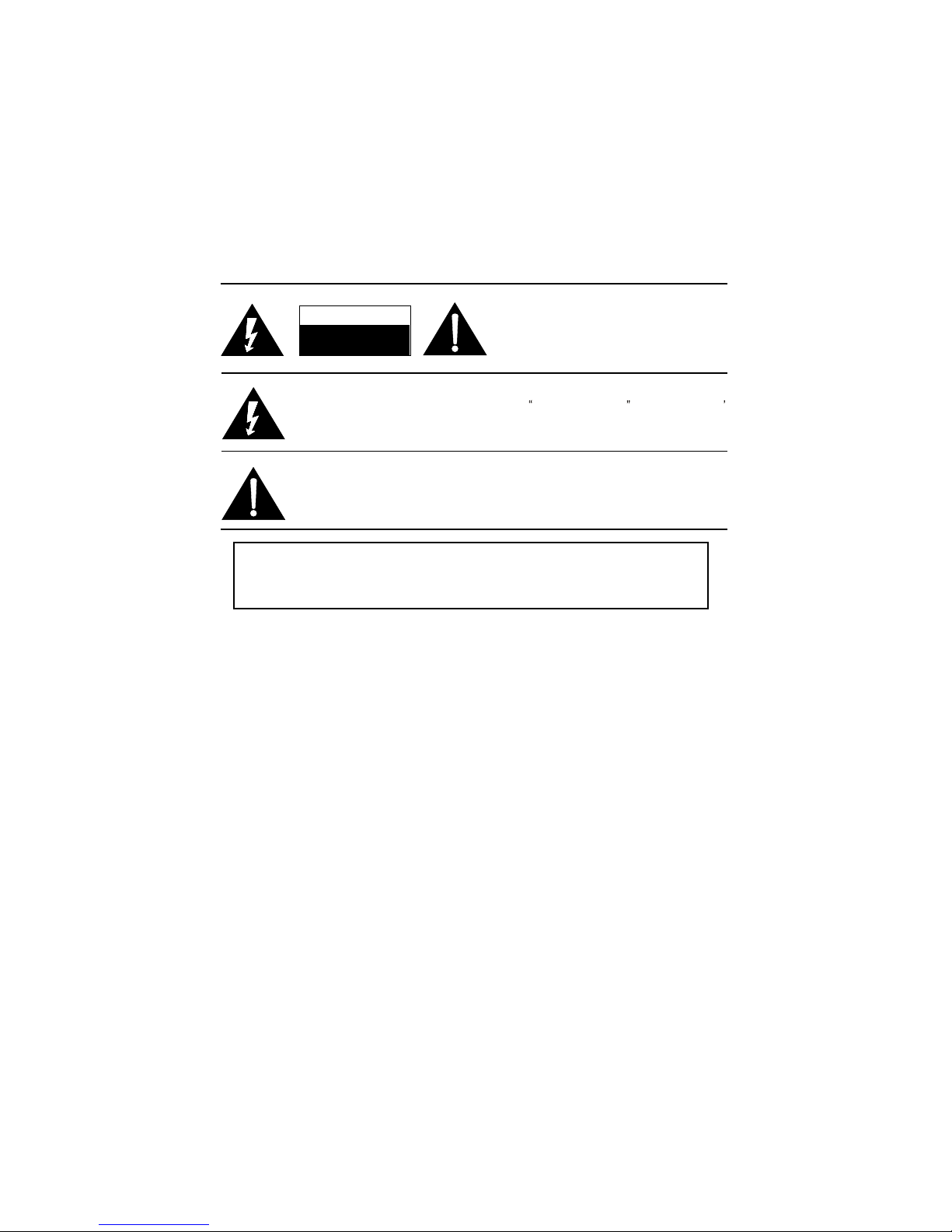
The lighting flash with arrowhead symbol, with an equilateral triangle is intended to
alert the user to the presence of uninsulated voltage within the products
enclosure that may be of sufficient magnitude to constitute a risk of electric shock to
the person.
The exclamation point within an equilateral triangle is intended to alert the user to the
presence of important operating and maintenance (servicing) instructions in the
literature accompanying the appliance.
Use of controls, adjustments or procedures other than those specified herein may result in
hazardous radiation exposure.
CAUTION
RISKRISK OF ELECTRIC
SHOCKSHOCK DO NOT OPEN.OPEN.
2
dangerous
1、 Caution
3
FOR YOUR PERSONAL SAFETY
1. When the power cord or plug is damaged or frayed, unplug this television set from the wall outlet and refer servicing to
qualified service personnel.
2. Do not overload wall outlets and extension cords as this can result in fire or electric shock.
3. Do not allow anything to rest on or roll over the power cord, and do not place the TV where power cord is subject to
traffic or abuse. This may result in a shock or fire hazard.
4. Do not attempt to service this television set yourself as opening or removing covers may expose you to dangerous
voltage or other hazards. Refer all servicing to qualified service personnel.
5. Never push objects of any kind into this television set through cabinet slots as they may touch dangerous voltage
points or short out parts that could result in a fire or electric shock. Never spill liquid of any kind on the television set.
6. If the television set has been dropped or the cabinet has been damaged, unplug this television set from the wall outlet
and refer servicing to qualified service personnel.
7. If liquid has been spilled into the television set, unplug this television set from the wall outlet and refer servicing to
qualified service personnel.
8. Do not subject your television set to impact of any kind. Be particularly careful not to damage the picture tube surface.
9. Unplug this television set from the wall outlet before cleaning. Do not use liquid cleaners or aerosol cleaners. Use a
damp cloth for cleaning.
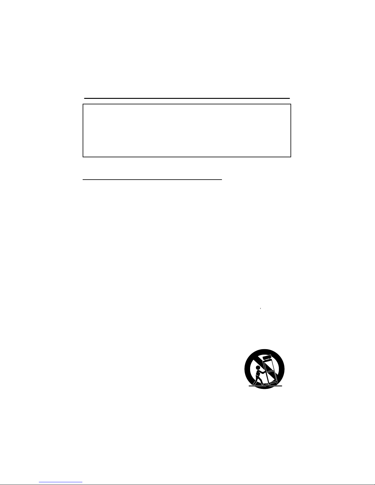
10.1. Do not place this television set on an unstable cart, stand, or table. The television set may fall, causing serious injury
to a child or an adult, and ser ious damage to the appliance . Use only with a cart or stand recommended by the
manufacturer, or sold with the television set. Wall or shelf mounting should follow the manufacturer s instructions, and
should use a mounting kit approved by the manufacturer.
10.2. An appliance and car t combination should be moved with care. Quick stops, excessive force, and uneven surfaces
may cause the appliance and cart combination to overturn.
CAUTION:
Read all of these instructions. Save these instructions for later use. Follow all Warnings and
Instructions marked on the audio equipment.
1. Read Instructions- All the safety and operating instructionsshould be read before the product is operated.
2. Retain Instructions- The safety and operating instructions should be retained for future reference.
3. Heed Warnings- All warnings on the product and in the operating instructions should be adhered to.
4. Follow Instructions- All operating and use instructions should be followed.
IMPORTANT SAFETY INSTRUCTIONS
4
PROTECTION AND LOCATION OF YOUR SET
11. Do not use this television set near water ... for example, near a bathtub, washbowl, kitchen sink, or laundry tub, in a
wet basement, or near a swimming pool, etc.
Never expose the set to rain or water. If the set has been exposed to rain or water, unplug the set from the wall
outlet and refer servicing to qualified service personnel.
12. Choose a place where light (ar tificial or sunlight) does not shine directly on the screen.
13. Avoid dusty places, since piling up of dust inside TV chassis may cause failure of the set when high humidity persists.
14. The set has slots, or openings in the cabinet for ventilation purposes, to provide reliable operation of the receiver, to
protect it from overheating. These openings must not be blocked or covered.
Never cover the slots or openings with cloth or other material.
Never block the bottom ventilation slots of the set by placing it on a bed, sofa, rug, etc.
Never place the set near or over a radiator or heat register.
Never place the set in enclosure, unless proper ventilation is provided.
PROTECTION AND LOCATION OF YOUR SET
15.1. If an outside antenna is connected to the television set, be sure the antenna system is grounded so as to provide some
protection against voltage surges and built up static charges, Section 810 of the National Electrical Code, NFPA No.
70-1975, provides information with respect to proper grounding of the mast and supporting structure, grounding of the
lead-in wire to an antenna discharge unit, size of grounding conductors, location of antenna discharge unit, connection
to grounding electrode, and requirements for the grounding electrode.
15.2. Note to CATV system installer : (Only for the television set with CATV reception)
This reminder is provided to call the CATV system attention to Article 820-40 of the NEC that provides
guidelines for proper grounding and, in particular, specifies that the cable ground shall be connected to the grounding
system of the building, as close to the point of cable entry as practical.
16. An outside antenna system should not be located in the vicinity of overhead power lines or other electric lights or power
circuits, or where it can fall into such power lines or circuits. When installing an outside antenna system, extreme care
should be taken to keep from touching such power lines or circuits as contact with them might be fatal.
17. For added protection for this television set during a lightning storm, or when it is left unattended and unused for long
periods of time, unplug it from the wall outlet and disconnect the antenna. This will prevent damage due to lightning
and power-line surges.
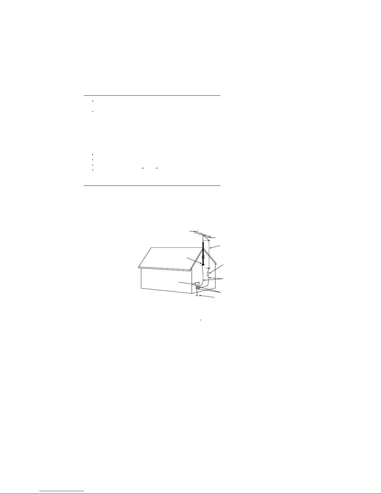
ANTENNA
LEAD- IN WIRE
ANTENNA DISCHARGE
UNIT (NEC SECTION
810-20)
GROUNDING
CONDUCTORS
(NECSECTION 810-21)
GROUND CLAMPS
POWER SERVICE GROUNDING
ELECTRODE SYSTEM
(NEC ART 250. PART H)
ELECTRIC SERVICE
EQUIPMENT
GROUND CLAMP
NEC-NATIONALELECTRICAL CODE
EXAMPLE OF ANTENNA GROUNDING AS PER
NATIONALELECTRICAL CODE
EXAMPLE OF ANTENNA GROUNDING AS PER NATIONAL ELECTRICAL CODE INSTRUCTIONS
a built-in
installer s

PFS (Product Functional Specification)
Date:
ProductView......:
Report by............: Linda Wen
Specs / Products
MasterData EM
Customer Id EM
Version 0.1
BOM No 04-D276BH-SA60
Brand
Rece
p
tion
-Tunin
g
- presets/channels 1.O
100 x
125
200
-Tunin
g
- technolo
gy
PLL x
VST x
-Tunin
g
- Indication
--- X
-Fre
q
Bands
UVSH
Full-Cable x
-IF Fre
q
38MHz
38.9MHz X
45.75MHz
-TV S
y
stems Off Air/Cabl
e
NTSC M (3.58 - 4.5)
NTSC (4.43 - 5.5)
NTSC (4.43 - 6.5)
NTSC 3.58 x
NTSC 4.43 x
PAL B/G x
PAL D/K
PAL I
SECAM B/G
SECAM D/K
-Add S
y
stems Ext In
NTSC 3.58
NTSC 4.43
NTSC Play Back x
PAL 60 x
-TV S
y
stems Multi
NTSC
PAL x
-Sound Systems
AV Stereo x
NICAM
German Stereo
American Stereo
Korean Stereo
Picture - Processin
g
-Scan
Standard x
-Scan Modes
4:3 x
4:3 Expand
-Wide Screen Switchin
g
-Combfilte
r
-Picture Control
Brightness x
Colour/Hue/ tint x
Contrast x
Color Temperature
Sharpness x
scan velocity modulation
LTI / CTI
Smart Pict. 4 Modes
Smart Pict. 5 Modes
Multiplicate picture scan mode
-Pict Enhancement
Active Control (without LNA)
Black Stretch x
dynamic skin
-Pict Noise Reduction
NR x
Page 1
M28L(G2)
2、 Specification of Chassis

PFS (Product Functional Specification)
Date:
ProductView......:
Report by............: Linda Wen
Specs / Products
M28L(G2)
Picture - Displa
y
-Display T
ype
DV - CRT - Normal Flat x
DV-CRT-Pure Flat
DV - CRT - Super Flat
-Screen Format
4:3 x
Expand 4:3
16:9
-Size
(
Visual)" - size/vis. cm
14
(
13V) - 37/34 cm
x
21(20V) - 55/51cm
25(00v) - 00/00cm
29(27v) - 72/68cm
34(00v) - 00/00cm
-Deflection S
y
stem(CRT onl
y)
1 Fh x
2 Fh
-Tube Technolo
gy (
CRT onl
y)
Iron x
Black Matrix x
Real Flat
-CRT Defl
090 degr x
100 degr
110 degr
500 degr
-CRT Gun
Stand Gun x
-CRT Ma
g
n field
Neutral
S Hemisphere x
North-Neutral
-Resolution
-Coatin
g(
only for D.V. sets
)
-White Point
Sound
-Leaflet Power
01W
02W
04W x
06W
10W
12W
20W
-RMS Power Intern
1x1W
2x1W
2x2W 21"
2x3W
2x4W
2x5W
2X6W
2X10W
-RMS Power Extern
-Surround Sound
-Sound Features
AVL
Mute x
Smart Sound (4 modes)
-Sound Control
Balance
Bass
Bass Boost
Smart Sound 4 Modes
Smart Sound 5 Modes
Treble
Treble Boost
Volume x
Sound - S
p
eakers
-S
p
eaker configuration
2x1 x
Page 2

PFS (Product Functional Specification)
Date:
ProductView......:
Report by............: Linda Wen
Specs / Products
M28L(G2)
-Speakers used
Normal Ran
g
e
x
Full Range
User Interface
-Interface Name
Full interface X
-Voice Control
-Menu
Cursor Control X
-Menu Colours
-Menu Lan
guag
es
Arabic
Chinese - Simplified
Chinese - Traditional
English X
Russian
Malay
Thai
-Record Select - sources:
-S
p
ecial Features
On/Off Time
r
x
Slee
p
timer
x
Game
x
Notebook
x
Calendar
x
Auto Standby x
Channel Copying x
Channel Naming
Channel Lock
Favorite Channel x
Manual Skip
channel navigation
Personal Zapping
Signal Strength Indicator
V-chip with Smart Lock
Hotel Mode x
Recall
AT
High Sensitive
-O
p
erational Features
Alternate Channel
Surf
-PP Features
One PP for all channels x
-Tunin
g
/ Install Features
Aut Cable/Ant. Select x
Auto Channel Prog x
Auto Store x
Factory Mode x
Fine Tuning x
Language Selection x
Manual Search/Store x
Service Mode x
-Clock/Timer Functions
Sleep timer x
Alarm Timer
Crystal Clock
Real Clock
Biological Clock x
-Local Controls Front
Channel + Mains Switch (Flush)
Volume + TV/AV
Auto search
menu
-Local Controls To
p
Channel +- x
Volume +- x
TV/AV x
menu x
-Indicators - screen
Page 3

PFS (Product Functional Specification)
Date:
ProductView......:
Report by............: Linda Wen
Specs / Products
M28L(G2)
-Indicators - front
RC Recvd LED x
SB LED x
-Numb of Loc Cont
(
incl Mains
)
5
7 x
-Number of Ind.
(
incl Mains
)
1
-Local Controls
(
Old
)
Remote Control
-Remote Control - sco
p
e
TV x
-Remote Control - t
yp
e
Standard x
-Remote Control - t
ypenr
E
F
x
Q
RC115
-Remote Control - features
Connectors Rea
r
-Scart RGB+Y/C+CVBS
-Scart RGB+CVBS
-Scart CVBS+Y/C
-Com
p
onent In (Y/U/V) Cinch
Ext(1) x
-Com
p
onent In (YPbPr) Cinch
-In Y/C+Cinch
(
CVBS+St
)
1x X
-In Y/C+Cinch
(
CVBS+Mo
)
-In Y/C+Cinch(St
)
-In BNC (CVBS
)
-In Cinch(CVBS+Mo
)
Ext(1)
-In Cinch
(
CVBS+St
)
Ext2
-In VG
A
-Out Y/C+Cinch(CVBS+St
)
-Out Cinch(CVBS+St
)
1x X
-Out Cinch
(
CVBS+Mo
)
1x
-Out Cinch Audio Stere
o
-Out Cinch Audio Mon
o
-Out Cinch Dolby Surround
-Out Cinch Subwoofer
-Di
g
Audio Ou
t
-Loudspeakers
-Control Busses
-Feature Slot
-ITV Smart Port
-Terr. Antenna in
75 Ohms (IEC type) x
Guide + IR Blaster Jack
Connectors Fron
t
-In Y/C + Cinch
(
CVBS+St
)
-In Y/C + Cinch(CVBS+Mo
)
-In Y/C + Cinch Stereo
-In Cinch
(
CVBS + St
)
-In Cinch (CVBS+Mo
)
Yes
-Head
p
hone Ou
t
Mini-Jack 3.5mm
-Feature Slot
-Cinch A/V in
Connectors Side
-In Y/C + Cinch
(
CVBS+St
)
-In Y/C + Cinch Stereo
-In Cinch
(
CVBS + St
)
Yes x
-In Cinch
(
CVBS + Mo
)
Yes
Page 4

PFS (Product Functional Specification)
Date:
ProductView......:
Report by............: Linda Wen
Specs / Products
M28L(G2)
-Headphone Ou
t
Mini-Jack 3.5mm
-Cinch A/V in
-Cinch A/V ou
t
Connectors To
p
-In Cinch (CVBS + St
)
-Headphone Ou
t
Connectors Mechanical
-Head
p
hone
-Cinch A/V in/ou
t
-Cinch Componen
t
-Cinch Y/C
St
y
lin
g
-Cabinet Name
-Confi
g
uration
DAS
Symm x
-Mechanics
-S
p
eaker Visibilit
y
Standard X
General
-Se
g
ment
Standard 4:3 X
-Chassis
M28L
-Software Deliver
y
Mode
-Software Version
-Mains Volta
g
e
110V - 270V
90 - 260V
90-276 AutoV
160 - 260 V
230 - 240 V X
-Mains Fre
q
uenc
y
50Hz X
-T
yp
e Mains Cord
FlatPin(Non-Polarised)
Australia / New Zealand
Euro
New Zealand
VDE
Power Consum
p
tion(P)TV in On
70W
Power Consum
p
tion SB in Watts
Less than 1 X
Less than 3
Less than 6
Less than 10
Power Consum
p
tion Semi SB in W
-Power in "ON" for
-Power in Standb
y
for
-Power in "OFF" for
-INDICATION on BACKCOVE
R
Made-in in Family Sheet X
FCC/Elect Shock caution label
Serial label X
Warning label on backcover X
-Channel
National Org.-NO X
Final E
quip
ment
-Packa
ging
- methods
2 Colour Printing
Brown Carton
White Carton
-Documents and manuals
Instruction Book (User Manual) x
Adbertising Brochure
Extended Warranty Brochure
Guarantee Doc X
Screen Sticker
Approbation Labels X
Easy installation Guide
Plastic Bag X
Page 5

PFS (Product Functional Specification)
Date:
ProductView......:
Report by............: Linda Wen
Specs / Products
M28L(G2)
Warning label X
Warranty Card
-Lan
guag
es DFU
Arabic
English x
Local Integration
Malay
Thai
-Cables Su
pp
lied
-Antenna Su
pp
lied
-Stand Su
pp
lied
-Aux E
quip
m Supplied
Batteries for RC (2 x AA) x
Miscellaneous
-A
pp
robation
CB
X
EMC X
-Tests
-Local Inte
g
ration
PIP/POP
-T
yp
e
---
-Features
Di
g
ital Reception
-Transmission
-Profile/Level
Di
g
ital Software
-Services
Di
g
ital Connections
-Di
g
ital Rear
Built-in Data S
y
stem
-Text Standard
No Text
-
(
Tele)text Features
1 Page text
10 Page text
-Nbr bac
g
rndpage/Mem Size
-Text Technolo
gy
-Digital Data handlin
g
-Program Guide
Built-in Clock/Time
r
-Type
-Features
Built-in Radio
-T
yp
e
Built-in PC dis
play
VG
A
XG
A
SVG
A
SXG
A
WVG
A
UXG
A
-PC Synch
-PC Control
Built-in TV dis
play
50i
60i
100i
60P
75P
Built-in Media Slots/ DVD drive
r
-Type of Medium
-T
yp
e of Dec
k
-Version of Deck
-Pla
y
back Formats
-Co
py
Protection Compliance
Phased Out Items
-Tuner/Frontend
-Sensitivit
y
-CRT EHT
-Li
g
htning Protection
-Accoun
t
Page 6

PFS (Product Functional Specification)
Date:
ProductView......:
Report by............: Linda Wen
Specs / Products
M28L(G2)
-XX(Radio Antenna in
)
-Non Volatile Memor
y
-In Y/C + Cinch(CVBS+Mo
)
Version of deck
Page 7
Tentativ
e
Tentativ
e
Tentativ
e
Tentativ
e
Confidential
TMPA8873CxBNG
2006/05/25
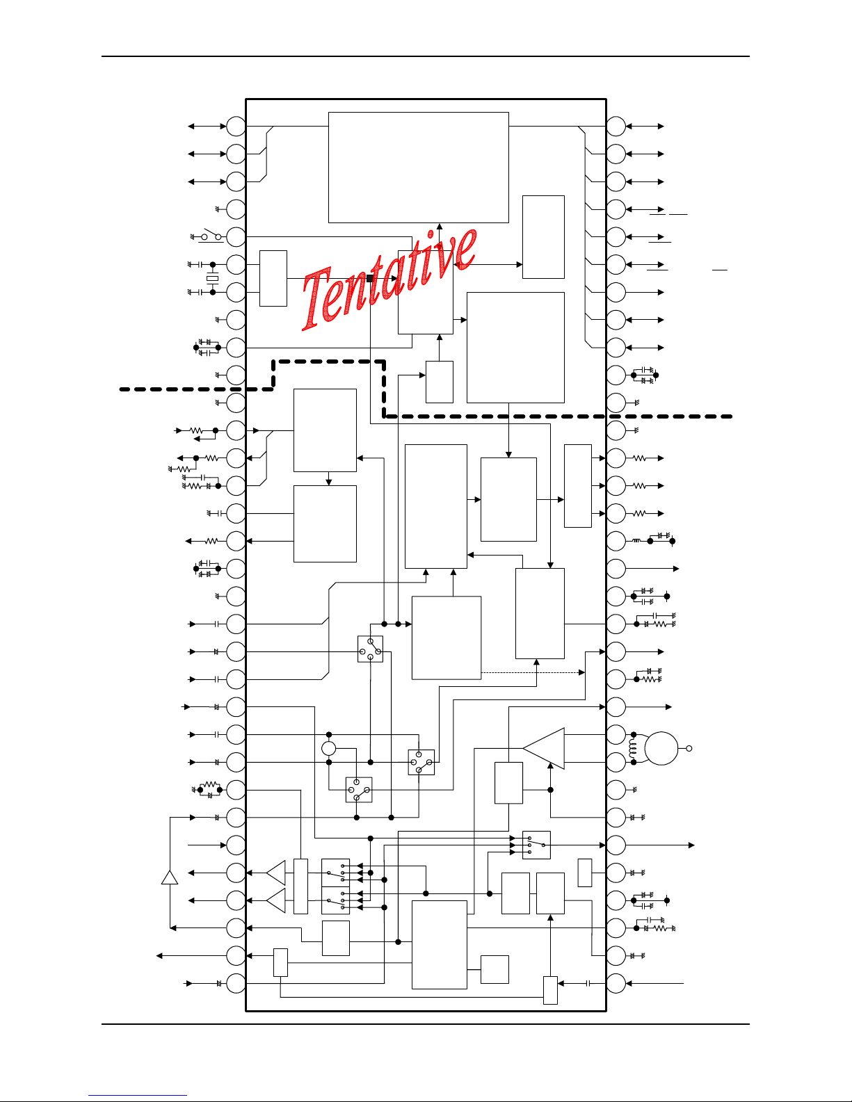
3
Block Diagram
EXT AU 1
+
P56
P51/SCL
P53/ADC8bit/TC1/Int2
IF IN
SAW
P31/Int4/TC3
P52/SDA
AU out 1
V2 CVBS/Y
Cr input
Y input
Cb input
APC Fil
PIF PLL
+
IF AGC
+
Black Det
FBP
SCP
TV DEF GND
P61/LED1/ADC8bit P63/LED2
+
RF AGC
P60/ADC8bit P30/Int3/RXIN
Hout
TV Dig GND
Vout
Bout
Gout
Rout
Cin
Vsaw
HAFC 1
+
Monitor /VM out
V1 IN 1Vpp
TVout 2Vpp
DC NF
+
H.correction
/2nd SIF in
+
DVcc
ABCL
IF GND
S-Reg.F
+
EXT AU 2
+
uP VVss
TEST
uP DVss
uP AVdd 5V
+
uP MPAGND
+
uP DVDD 5V
1 765432 8 14131211109 15 212019181716 22 282726252423 32313029
56 5052535455 49 434445464748 42 363738394041 35 333464 585960616263 57 51
8MHz
IF Vcc 5V
+
H/Lout / SIF out
Sync out / H/L out
AU Monitor out
ALC filter
A Vcc 8V
YC Vcc 5V
AU out 2
P20/Int5/Stop
P40/PWM14bitReset
P50/PWM7bit/TC2/Int0
TV AGND
+
+
+
-6dB
+
+
+
PIF Proc.
PAL/ NTSC demod
Auto.VCO
alignment
Vert.Proc.
V.C/D
V.ramp
V.geometry
V.Drive
Chroma Proc.
C-BPF
PAL/NTSC
Hor.Proc.
Sync.sepa
Hor.VCO HAFC-1
HAFC-2 H-shift
Cut-off
Drive
RGB switch
Brightness
Half-tone
Transparent
XO
870X CPU core
STOP/IDLE mode
I/O
10 I/O port
14-bit PWM x1
7-bit PWM x1
8-bit ADC Ext.x3
Int.x1
Romote preprocessor
16-bit int.timer x2
8-bit int.timer x2
Watchdog timer
Interrupt
Ext.x5 Int.x11
IIC bus interfece
Ext.x1 Int.x1
AFT
OSD R/G/B/Ys/I
Font:16 x 18
Display:32C x 12L
Color:8
Character:384
Half-tone
Transparent
CCD
Y Proc.
C-Trap
Black stretch
Y gamma
Sharpness
Base Band Proc.
TINT
1H DL Int/Ext switch
Color Uni-color
RGB Matrix
ROM:䋴䋸kB
RAM:2kB
ROM correction
Sound
TRAP
IF
AGC
AGC
DET
䋫
䋫
䋫
䋫
Reg.
FM
DEMO
De-emp
(on/off)
ALC
BPF
SW
VM
ATTATT
+
3、Specification of IC
3.1
Tentativ
e
Tentativ
e
Tentativ
e
Tentativ
e
Confidential
TMPA8873CxBNG
2006/05/25
4
Basic Structure
1. Internal Connections
TMPA8873 has two pieces of IC chip in one package, using Multi-Chip-Package (MCP) technology. One is a
micro controller (MCU) and the other one is a signal processor (SP) for a color TV. There are some in ternal
connections between these two ICs for handling below signals.
Signal Name Direction Description
1 SCL M to S Internal IIC bus SCL
2 SDA Bi-direction Internal IIC bus SDA
3 OSD R M to S OSD signal connection
4 OSD G M to S OSD signal connection
5 OSD B M to S OSD signal connection
6 OSD Y/BL M to S OSD display control
7 OSD I, CS OUT M to S OSD half-tone control/Test pattern signal
8 C-Video S to M Composite video signal from internal video switch, for CCD
9 C-Sync S to M Composite sync. signal from sync. Separator, for CCD
10 HD S to M Horizontal timing pulse regenerated from FBP, for OSD
11 VD S to M Vertical timing pulse from sync. Separator, for OSD
12 CLK M to S 8 MHz clock
13 AVDD M to S Reference voltage for C-Video interface
14 ADC S to M A/D converter monitoring RF-AGC, R-Y and B-Y
Functions of SP from MCU are controllable through the IIC bus of the internal connections.
2. Power Supply
TMPA8873 has some power supplies and GND pins. Power supplies related MCU must be applied at the
first. Power supplies for H.V
CC
and TV D.VCC are the second with at least 100 ms delay after MCU power ON.
The other power supplies are the last, which are recommende d to be supplied from a regulator ci rcuit using
FBP.
3. Crystal Resonator
TMPA8873 requires only one crystal resonator, in stead that a conventional two-chip solution requires two
resonators at least, one for MCU and the other one for SP. An oscillation clock with the crystal resonator of
TMPA8873 is supplied for MCU operation, PIF VCO automatic alignment, alignment free AFT, chroma
demodulation and horizontal oscillation. The oscillation frequency is very important so that those of functions
work properly, so that designing the oscillation frequency accurately is required. The spec of crystal is
recommended to be within
f
osc
: 8 MHz +/−20 ppm
ftemp: 8 MHz +/−40 ppm (−20°C to +65°C)
While RESET of MCU is active, the MCU function stops. Hardware and software initialization sequence
including power supplies control is required, because status of any hardware after the RESET peri od is
unknown especially horizontal oscillator which is a very basic timing generator of SP operation.
Tentativ
e
Tentativ
e
Tentativ
e
Tentativ
e
Confidential
TMPA8873CxBNG
2006/05/25
5
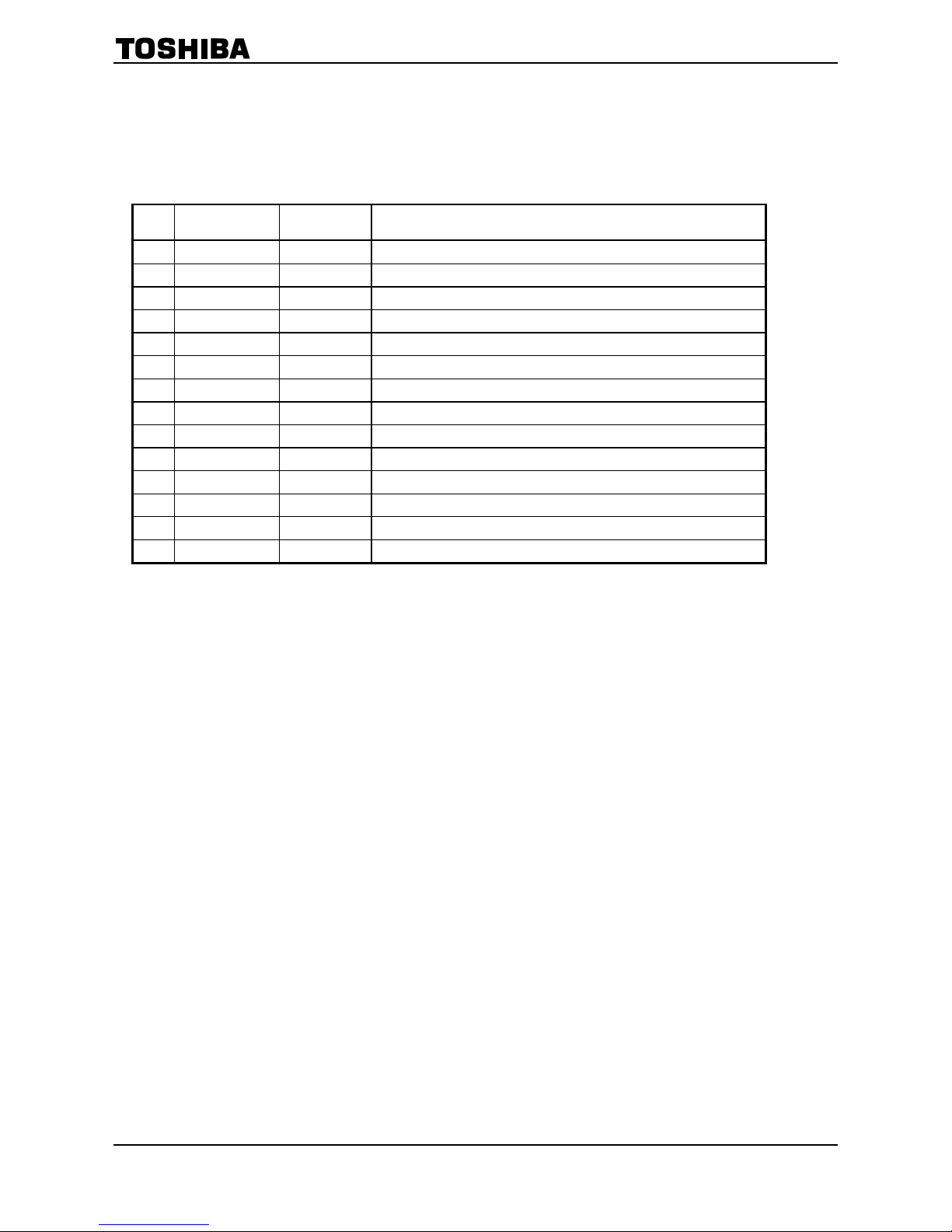
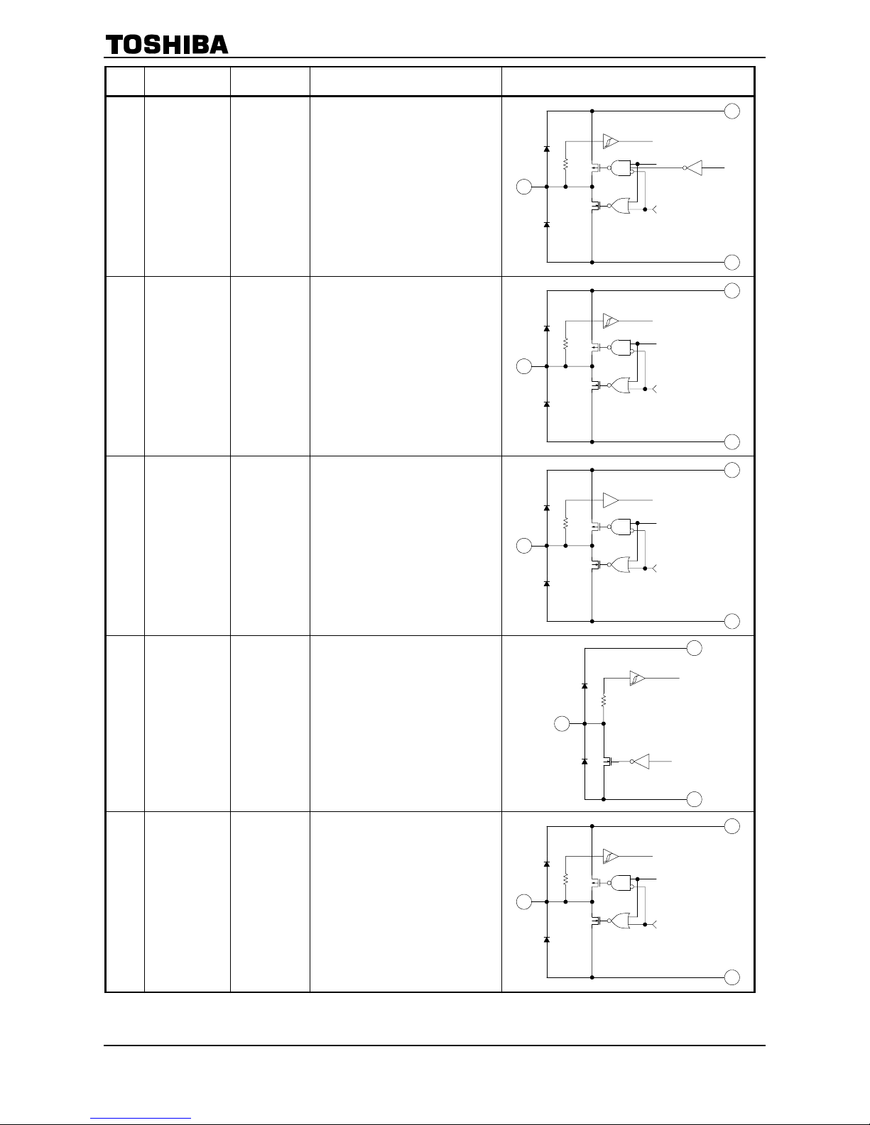
TERMINAL INTERFACE
MCU BLOCK
Pin
No.
Pin Name I/O Function Interface Circuit
1
P61
(/KWU5)
(AIN5)
(LED1)
I/O
(Input)
(Input)
(Output)
Key on wake up input
A/D converter analog input
LED output
2
P60
(/KWU4)
(AIN4)
I/O
(Input)
(Input)
Key on wake up input
A/D converter analog input
3
P53
(/KWU0)
(AIN0)
(TC1)
(INT2)
(SCK1)
I/O
(Input)
(Input)
(Input)
(Input)
(I/O)
Key on wake up input
A/D converter analog input
Timer/counter input
External interrupt input
SIO serial clock input / output
4 up DVss
Power
Supply
GND
⎯
5 Reset I/O
Reset signal input or watchdog
timer output
Address trap reset output
System clock reset output
Tentativ
e
Tentativ
e
Tentativ
e
Tentativ
e
Confidential
TMPA8873CxBNG
2006/05/25
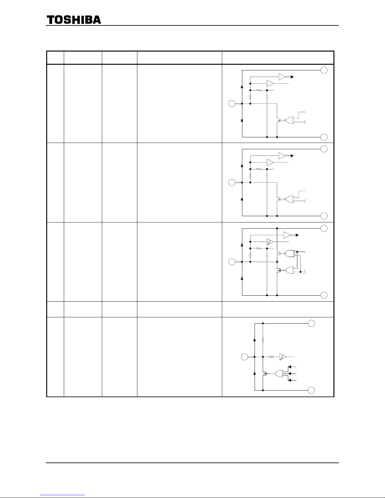
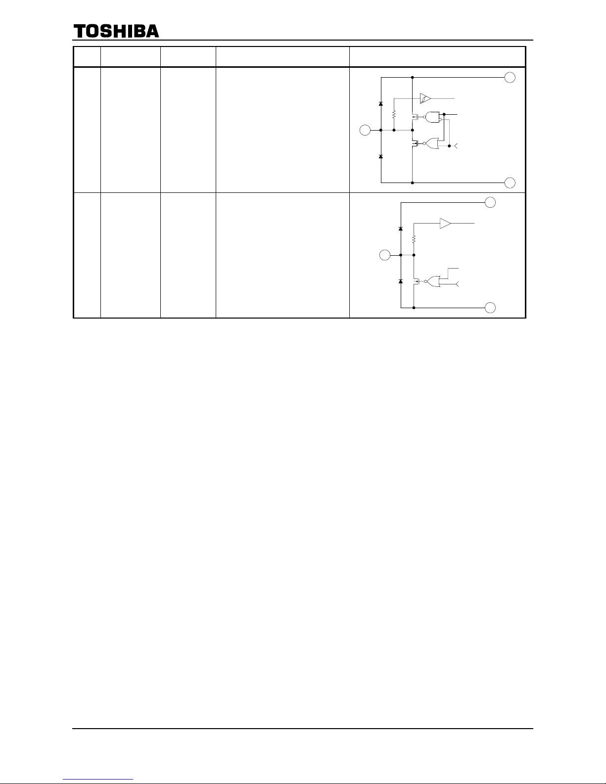
6
Pin
No.
Pin Name I/O Function Interface Circuit
67Xout
Xin
Output
Input
X’tal connecting pins
8 TEST Input Test pin for out-going test
9 up DVdd
Power
Supply
Vdd
Supply 5V
-
10 up VVss
Power
Supply
GND for Slicer circuit
⎯
54 up AGND
Power
Supply
GND for Oscillator circuit
⎯
55 up AVdd
Power
Supply
Vdd for Oscillator circuit
Supply 5V
⎯
56 P56 I/O
57
P52
(SDA)
(SO1)
I/O
(I/O)
(Output)
IIC bus serial data input / output
SIO serial data output
Tentativ
e
Tentativ
e
Tentativ
e
Tentativ
e
Confidential
TMPA8873CxBNG
2006/05/25
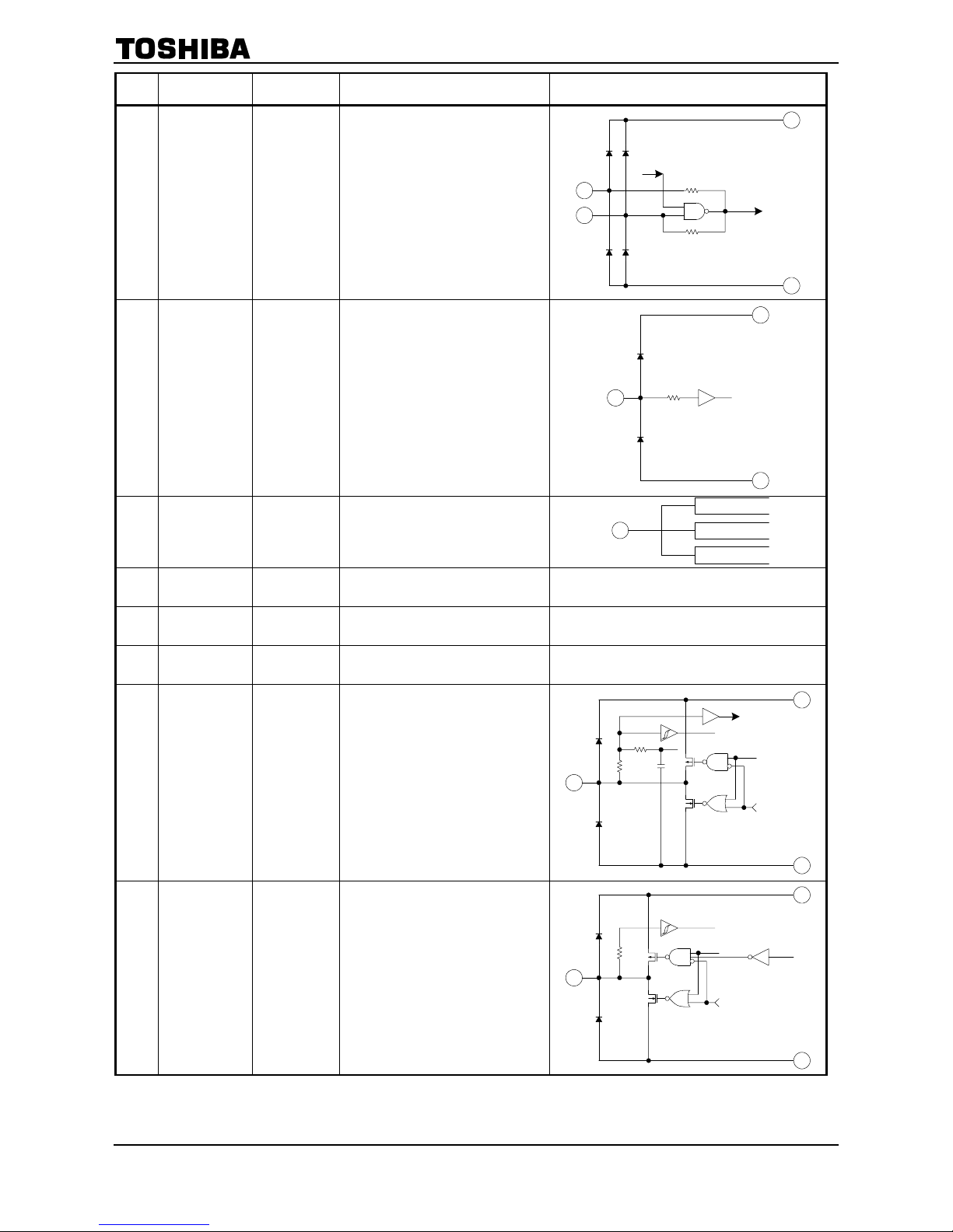
7
Pin
No.
Pin Name I/O Function Interface Circuit
58
P51
(SCL)
(SI1)
I/O
(I/O)
(Input)
IIC bus serial clock input / output
SIO serial data input
59
P50
(/PWM8)
(TC2)
(INT0)
I/O
(Output)
(Input)
(Input)
7-bit D/A conversion (PWM)
output
Timer/Counter input
External interrupt input
60
P40
(/PWM0)
I/O
(Output)
14/12-bit D/A conversion (PWM)
output
61
P20
(/INT5)
(/STOP)
I/O
(Input)
(Input)
External interrupt input
STOP mode release signal input
62
P31
(INT4)
(TC3)
I/O
(Input)
(Input)
External interrupt input
Timer/Counter input
Tentativ
e
Tentativ
e
Tentativ
e
Tentativ
e
Confidential
TMPA8873CxBNG
2006/05/25
8
Pin
No.
Pin Name I/O Function Interface Circuit
63
P30
(INT3)
(RXIN)
I/O
(Input)
(Input)
External interrupt input
Remote control signal
preprocessor input
64
P63
(LED2)
I/O
(Output) LED output
 Loading...