

Page 1
Page 2

Safety Precautions
This manual contains important information for the operator to operate this product safely and cor
rectly and avoid bodily injury and property damage.
Grasp the meanings of the following marks and their descriptions before reading this manual.
•Hazard Classifications
Indicates a potentially hazardous situation which, if not avoided, could result in
<^WARNING
/j\cAUTIQN
(Note) 1. Serious injury means loss of sight, injury, burns (high temperature, low temperature), electrical
shock, fracture, or intoxication which leaves aftereffects or requires hospitalization or need to
go the hospital for a long time.
2. Injury means hurt, burn, or electric shock which does not require hospitalization orgoing to the
hospital fora long time.
3. Property damage means extended breakdown of assets and materials.
serious injury or death.
Indicates a potentially hazardous situation which, if not avoided, can result in
minor or moderate injury, or property damage. It can also be used to alert
against unsafe practices.
•Notation of Markings
Indicates a "may not" mark.
Q
O
A
(Note) The descriptions of forbiddance, mandatory, and caution marks are subject to change,
depending on the labels on the main unit.
The concrete forbiddance is indicated with a pictograph or wording.
Indicate a mandatory action that you should never fail to do.
The concrete content is indicated inside or near the circle with a pictograph or wording.
Indicates a caution.
The concrete content is indicated inside or near the triangle.
6F8C0926
Page 3
Make sure warning markings are attached on the model 2000.
If any of them are missing or the wording is illegible, contact Toshiba’s Service Department.
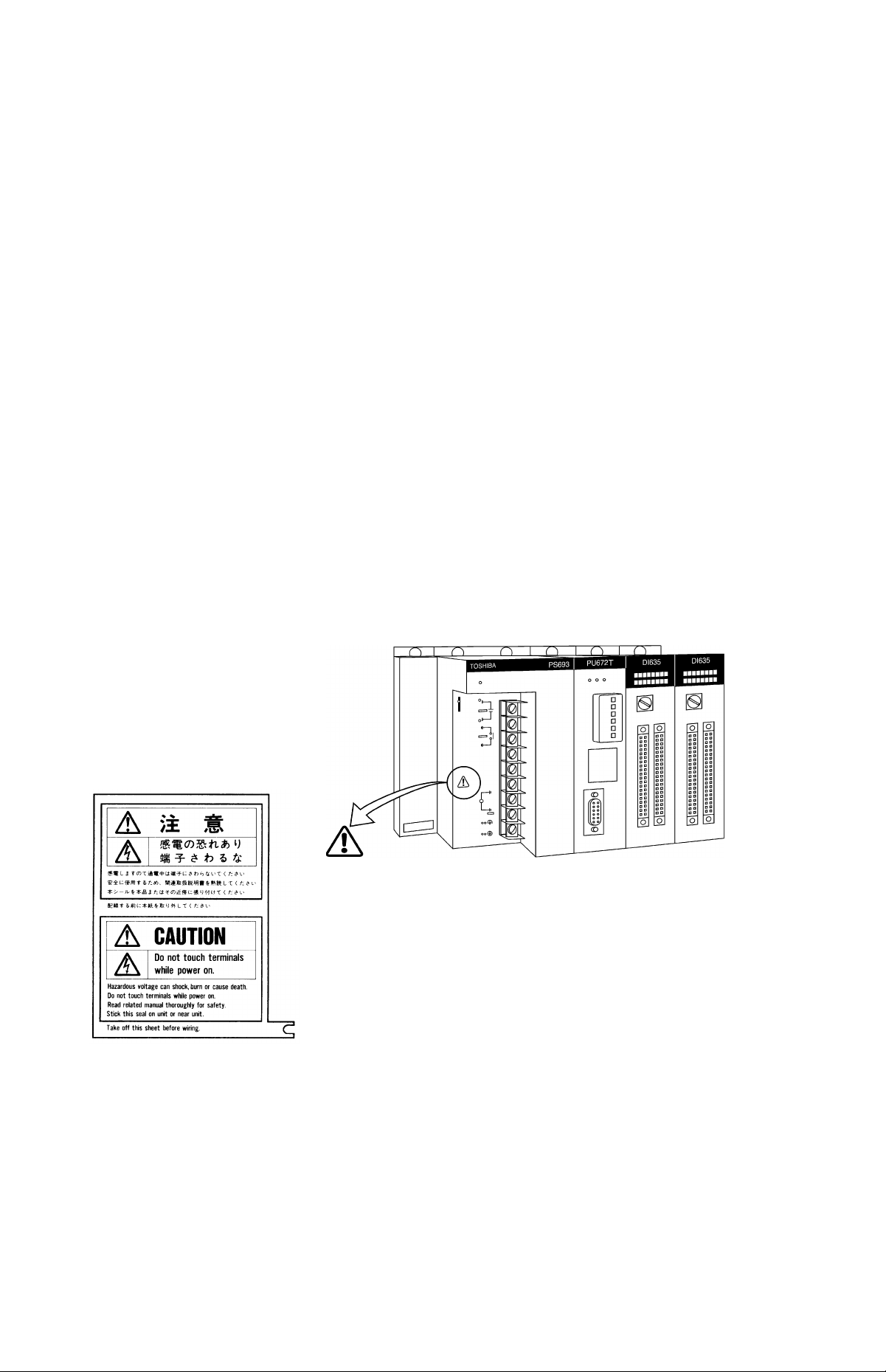
[Warning Mark on the model 2000]
This is the warning mark for dangerous location. It is attached to the equipment at positions
where there is a risk of electric shock and at positions where there is a risk of damage to
the equipment through incorrect wiring.
A
(1) Keep hands away from terminals, especially the input terminal of the power supply while power is
on, to avoid the risk of electric shock.
(2) Turn off power before installing or removing modules, terminal blocks, or wires.
(3) Applying excess power voltage to the model 2000 can cause failure or malfunction. Apply power of
the specified ratings described in this manual.
(4) Turn off the power of the tool (a personal computer, etc.) before connecting the connector to the tool
port. Afterwards, turn on power.
Avoid short-circuiting between the tool connector pins with the cover, etc.
Take the following precautions where this mark is found.
[Safety Label]
The safety label as shown on the left both in Japanese and English
is attached to the power supply terminal of the model 2000. (exept
the 24Vdc input power supply module)
Remove the mount paper before wiring
Peel off either of the Japanese and English labels from the mount
paper and stick it to the model 2000 or near the power terminal
where it can be readily seen.
In the event the seal is damaged, contact the dealer.
NOTE
Marks printed at pages in this manual should always be read carefully.
Be sure to read them in handling your model 2000.
Sequence Controller S2T
Page 4

2. Precautions on Installation
^WARNING
Mandatory
Be sure to ground the model 2000. The
protective ground terminal of the model 2000
must be connected to an external protective
earth.
Operation without grounding may cause
accidental fire or shock.
A CAUTION
»
Mandatory
Avoid the following locations when installing or
storaging the model 2000.
• Locations where there is dust, salinity or ion
particles
• Locations where there are corrosive gases
(SO2, HjS) or flammable gases
• Locations where vibration or shock occurs
beyond the allowance
• Locations where there is condensation due
to sharp temperature variations
• Locations where the ambient temperature
exceeds the allowance range
• Locations where the relative humidity
exceeds the allowance range
• Locations where the model 2000 is exposed
to direct sunlight
• Locations where strong electric radiation or
magnetic field is generated
»
Mandatory
Improper the installation or wiring of the
system can cause not only insufficient
performance but also malfunction and failure of
the model 2000.
Installation in an unspecified direction or
improper installation can cause fall-off, fire,
interference, or malfunction of the model 2000.
»
Mandatory
Install the model 2000 at a place where
maintenance and inspection are easy to do.
Otherwise, recovery from failure may take
much more time, leading to a serious accidents.
Gr
Forbidden
Do not cover the hole of the model 2000, and
the ventilator/air inlet of the system.
Otherwise, overheating, etc. can cause fire or
malfunction.
Mandatory
Avoid entering wire scraps or other foreign
debris into the model 2000, and related
equipment. Otherwise, it can cause fire, failure
or malfunction.
6F8C0926
III
Page 5

3. Precautions on Wiring
<!>WARNING
Mandatory
Be sure to turn off power before wiring.
Otherwise, it can cause electric shock or
malfunction of the model 2000.
ACAUTION
Mandatory
Apply power of the specified ratings
described in the manual.
Applying excess power voltage to the model
2000 can cause explosion or fire.
Mandatory
Be sure to use crimp-style terminal with
insulating sheath or insulating tape to cover
the conductive parts when wiring modules so
that no conductive parts are exposed.
Handle the terminal cover with care so as not
to fall off or get damaged.
Be sure to fix the cover on the terminal block
after wiring.
An exposed conductive part can cause
electrical shock.
a
Mandatory
It is assumed that the users have general
knowledge of industrial electrical control
systems.
IV
Sequence Controller S2T
Page 6

4. Precautions for Operation
^WARNING
»
Mandatory
Configure emergency stop interlocking circuit
outside the model 2000. Otherwise, failure
and malfunction of the model 2000 can cause
human injury, machine damage or serious
accidents.
ACAUTION
o
Forbidden
The power supply modules, the CPU modules,
the direct I/O modules and the expansion
interface are dedicated to the model 2000.
Mount them on the bases of the model 2000.
Do not use them by themselves for other
purposes.
Otherwise, it can cause electrical shock or
injury or malfunction.
»
Mandatory
Be sure to keep the terminal block covers
closed during power ON. Do not touch the
terminals. Otherwise, it can cause electrical
shock or injury.
»
Mandatory
When you attempt to perform program change,
forced output, RUN/HALT controls, etc during
operation, carefully check for safety.
Improper operation or negligence in checking
safety conditions can cause machine damage
or serious accidents.
«
Mandatory
Mount the modules on the base securely until
they click, and fix them on the base with
screws.
Insufficient installation can cause failure or
malfunction.
«
Mandatory
Sample programs and circuits described
in this manual are provided for explaining
the operations and applications of the S2T.
You should test completely before using
them as a part of your application system.
6F8C0926
»
Mandatory
Set the operating switches of the model
2000 according to this manual.
Improper setting can cause failure or
malufunction.
»
Mandatory
Install fuses suited to the load current
capacity in the external circuits for the relay
output module, preventing from overload.
Otherwise it can cause machine damage or
accidents.
Page 7

O
Mandatory
Configure the external circuit to turn on power
according to the following sequence.
Turn on the power of model 2000
^ Turn on the power for the I/O module and
external load power supplies
Otherwise, it can cause machine damage,
malfunction or accidents.
»
Mandatory
It is recommended to use an external power
supply that provides power for both the I/O
module and the loads. If not possible,
configure the external circuit so that the
external power required for output modules
and power to the loads are switched ON/OFF
simultaneously.
Also, be sure to turn off power to the loads
before turning off power to the S2 T for system
safety.
Sr
Forbidden
Turn off power immediately if the S2T or
related equipment emitting smoke or odor.
Operation under such situation can cause f ire
or electrical shock. Also unauhorized repairing
will cause fire or serious accidents. Do not
attempt to repair. Contact Toshiba for
repairing.
5. Safety Precautions on Maintenance and Inspection
<!>WARNING
»
Mandatory
Turn off power when removing any units,
modules, terminal blocks or wired cables after
installing.
Otherwise exposed conductive pants of wire
or on the rear of terminal blocks can cause
electrical shock.
Sr
Forbidden
Do not disassemble or modify the S2T and
related equipment in hardware nor software.
Otherwise it can cause failure, malfunction,
electrical shock or injury.
(Sr
Forbidden
Be sure not to connect the opposite electrode
of the battery or charge, the battery.
Also, do not try to disassemble the battery or
make it short-circuited or throw it into fire or
use it in overheated condition.
Otherwise it can cause fire or explosion.
VI
Sequence Controller S2T
Page 8

ACAUTION
0^
Forbidden
Be careful not to hit or fall off the model 2000
by accident.
Excess shock can cause failure.
Mandatory
Touch a grounded metal part to discharge the
static electricity on your body before touching
the model 2000.
Otherwise, charged static electricity on your
body can cause malfunction or failure.
Mandatory
Use soft cloth to clean the model 2000.
Use water-dipped and squeezed cloth to clean
it if dirty.
Leaving the model 2000 dirty can cause
mistaking or malfunction.
9
Mandatory
Place any modules removed from the unit on a
conductive mat or conductive bag (containing
a spare board, etc.) on an grounded desk.
Otherwise, static electricity can damage
components of the module.
0
Forbidden
Do not apply benzene and thinner when
cleaning the model 2000.
Otherwise, it can cause deformity or
descoloration the panel or case of the model
2000.
6.Safety Precautions on Replacing Components
<^WARNING
Mandatory
Turn off power of the model 2000 before
replacing the power fuse or warning fuse.
Otherwise, it can cause electrical shock or fire.
6F8C0926
Mandatory
Replace the fuse or battery with a new one
specified.
Otherwise, it may malfunction or cause fire.
VII
Page 9

»
Mandatory
The relays used in the relay output module
have ON/OFF life mechanically.
Use them within their mechanical life times is
described in this manual.
Replace the module if exceeded.
Acaution
a
Mandatory
In an annual average temperature of 30°C or
less, replace the battery every four years;
replace it every two years in an average
annual temperature higher than 30°C.
An exhausted battery can cause malfunction
and lose data and programs stored in S2T,
resulting in machine damage or accidents,
depending on the application.
7. Safety Precautions in Daily Operation
C^WARNING
«
Mandatory
Apply power of the specified ratings (voltage
fluction range, frequency, output rating, etc.)
described in this manual.
Otherwise, it can cause malfunction,
machine damage or fire due to overheat.
«
Mandatory
Turn off power immediately if the ambient
temperature or internal temperature exceeds
beyond normal range or if failure is occurred in
the model 2000.
Contact Toshiba for repairing.
Operation under such situation can cause fire
or electrical schock.
Vili
Sequence Controller S2T
Page 10

ACAUTION
0
Forbidden
Do not touch any components, terminals,
connectors or printed circuit boards in the
module.
Otherwise, it can cause the 1C or LSI or the
like to be broken by static electricity, resulting
in failure or malfunction.
Also, the edge of components can cause
injury.
0
Forbidden
Do not disassemble or modify the S2T and
related equipment.
Otherwise, it can cause malfunction or failure.
0
Forbidden
Do not forcibly bend or pull or distort the
power cord and other cables. Otherwise, they
can be cut off or cause overheat.
0
Forbidden
Do not enter wire scraps or other foreign
debris into the S2T and related equipment.
Also, do not insert metal parts into them.
They can cause fire or accidents.
8. Safety Precautions on Disposal
^WARNING
Forbidden
Do not throw lithium batteries into fire.
Otherwise, they can explode.
ACAUTION
Mandatory
Observe local regulations for disposal of the
lithium batteries or the model 2000.
6F8C0926
IX
Page 11

Limitation of Appiications
■ The model 2000 has been designed and manufactured for use in an industrial environment.
However, the model 2000 is not intended to be used for systems which can endanger human
life (note 1).
■ Consult Toshiba if you intend to use the model 2000 for a special application which involves
human life and has great influence on the maintenance of the public function (note 2). This is
why such application requires special care on the operation, maintenance, and control of the
system (note 3).
(Note 1) The systems which can endanger human life are life maintenance systems, equip
ment installed in the surgery, and other medical equipment.
(Note 2) The systems which involve human life and have great influence on the maintenance
of the public function mean the main control system of a nuclear power plant, safety
and protection system of a nuclear power facility, transport operation and control sys
tems for mass transportation, control systems of aviation and space systems, and
other systems and subsystems where safety is critical.
(Note 3) "Special care" means to build a safety system (foolproof design, fail safe design,
redundancy design, etc.) in full consultation with Toshiba’s engineers.
Immunity
Toshiba is not liable for any loss caused by fire, earthquake, action by a third party, or other
accidents, or the operator’s intentional or accidental misuse, incorrect use, or use under
abnormal condition.
Toshiba is not liable for any incidental loss caused by the use or non-use of this product, such
as loss of business profits, suspension of business, or loss or change of data on memory.
Toshiba is not liable for the loss caused by an operation contradictory to any of the instructions
stated in this manual.
Toshiba is not liable for the loss caused by an incorrect operation in combination with other
equipment.
Toshiba is not liable for the loss caused by a malfunction in combination with an application
program made by the customer.
NOTE:
Use cellular phones and PHSs at least one meter away from the working the model 2000
transmission cables, and I/O bus cable. Otherwise, the system can malfunction.
Sequence Controller S2T
Page 12

About this manual
This manual describes an overview, specification, and installation, operation, and
maintenance and inspection of the hardware of Toshiba’s sequence controller S2T for
the Integrated Controller Vseries model 2000 (hereinafter called "S2T," which is also
called "model 2000" or the "equipment" when no distinction is needed).
The following types of S2T are available to realize cost-performance suited to your
application.
• PU662T: CPU station module, 32K-steps, 90 ns/basic instruction, RS485 port
• PU672T: CPU station module, 64K-steps, 90 ns/basic instruction, RS485 port,
1MB memory
At first, be sure to read "Safety Precautions" before operating the model 2000.
Read this manual throughly before using the S2T. Also, keep this manual and
related manuals so that you can read anytime while the S2T is in operation.
This manual has been written for users who are familiar with Programmable Control
lers and industrial control equipment. Contact Toshiba if you have any questions
about this manual.
6F8C0926
XI
Page 13

The S2T Related Manual
The following documents are available for S2T .
S2T User’s Manual - Basic Hardware (6F8C0926)
Describes the S2T system configuration, and explains the specifications, installa
tion, wiring, maintenance and troubleshooting for the S2T’s basic hardware.
S2T Use’s Manual - Functions (6F8C0928)
Provides the information for designing S2T user program, such as S2T internal
operation, memory configuration, I/O allocation.
T Series Instruction Set (Ladder, SFC) (UM-TS03***-E004)
Detailed explanations of ladder and SFC programming, two of the languages of the
S2T/T3H/T3/T2N/T2E/T2/T1S/T1 programmable controllers.
T-PDS for Windows Basic Operation Manual (UM-TS03***-E038)
Installation and basic key operations of the T-series Program Development System
(T-PDS) software for windows.
T series Computer Link Function User’s Manual (UM-TS03***-E008)
Describes the Tseries computer link configuration, and explains the protocol, soft
ware procedure, wiring to communicate between the Tseries PCs.
High Function Analog Mdule User’s Manual (6F8C0860)
Describes the specifications and operation of high function Analog Mudule
(AD668/DA664/TC618/RT614).
Pulse Input Module Manual (PI632/PI672) (6F8C0841)
Describes the specifications and operation of Pulse Input Module (PI632/PI672).
Communication Interface Module Manual (CF611) (6F8C0843)
Describes the specifications and operation of Communication Interface Module
(CF611).
2-Axis Positioning Controller Manual (MC612) (6F8C0842)
Describes the specifications and operation of 2-Axis Positioning Module(MC612).
XII
TOSLINE-S20 User’s Manual (6F8C0890)
Describes the system configuration, and explains the functions, performance and
operation of TOSLINE-S20.
Sequence Controller S2T
Page 14

TOSLINE-F10 User’s Manual (6F8C0844)
Describes the system configuration, and the specifications, wiring and operationg
of remote I/O data link system TOSLINE-F10.
DeviceNet Scanner Module Manual (6F8C0845)
Describes the system configuration,and explains the specifications, installation,
wiring of Device Net.
Ethernet Module Operation Manual (6F8C0879)
Describes the specifications, wiring and operating of Ethernet Module (EN611/
EN631/EN651)
6F8C0926
XIII
Page 15

CONTENTS
Safety Precautions.......................................................................i
Limitation of Applications............................................................x
Immunity.....................................................................................X
About this manual..................................................................................xi
The S2T Related Manual......................................................................xii
Chapti System Configuration
1.1 S2T configuration as Station Module
1.1.1 S2T basic configuration............................................................2
1.1.2 S2T System configuration
1.1.3 Unit configuration......................................................................5
1.2 S2T CPU Module
1.2.1 Overview.................................................................................10
1.2.2 Status display LEDs...............................................................11
1.2.3 Operation Mode Switch..........................................................11
1.2.4 Setting Switches of Operation Mode
1.2.5 Programmer port of RS232C..................................................13
1.2.6 LINK port of RS485................................................................ 14
1.3 Computer link mode
1.3.1 Computer link function............................................................18
............................................................
........................................................
........................................................
.........................
................................
......................................
1
2
3
10
12
18
XIV
1.3.2 System configuration..............................................................19
1.3.3 Setup procedure
1.3.4 RS-485 cable connection.......................................................21
1.3.5 RS-232C cable connection.....................................................23
1.3.6 Mode setting...........................................................................23
1.3.7 Communication parameter setting
1.3.8 Computer link protocol............................................................25
.....................................................................
.........................................
20
24
1.4 Free ASCII mode.............................................................27
1.4.1 Free ASCII communication function.......................................27
1.4.2 System configuration..............................................................29
1.4.3 Setup procedure
1.4.4 RS-485 cable connection.......................................................31
1.4.5 Mode setting...........................................................................32
1.4.6 Communication parameter setting
.....................................................................
.........................................
30
33
Sequence Controller S2T
Page 16

------------
1.4.7 Message format......................................................................34
1.4.8 Programming..........................................................................35
1.4.9 Related instruction..................................................................40
CONTENTS
1.4.10 Sample programs
1.5 Units................................................................................51
1.5.1 Bases
1.5.2 Expansion interface................................................................53
1.5.3 Expansion cables
1.6 Power Supply Module......................................................54
1.6.1 Power Supply Module.............................................................54
1.6.2 Power capacity consideration.................................................57
1.7 I/O Modules.....................................................................60
1.8 Network Modules
.....................................................................................
Chapt2 Specifications
2.1 General Specifications
2.2 External dimensions........................................................68
...................................................................
...................................................................
............................................................
.................................
....................................................
48
51
53
62
65
65
2.3 I/O Module Specification
.................................................
70
ChaptS Precautions for I/O Modules..........111
3.1 Precautions for DC Input Modules
3.2 Precautions for AC Input Modules.................................115
3.3 Precautions for DC Output Modules..............................117
3.4 Precautions for AC Output Modules..............................120
3.5 Precautions for Relay Output Modules
3.6 Precautions for Analog Input Modules
3.7 Precautions for Analog Output Modules........................123
...................................
.........................
..........................
121
Ill
122
Chapt4 Installation and Wiring..................125
4.1 Operating environment..................................................125
4.2 Installing bases
.............................................................
126
6F8C0926
4.3 Mounting the Modules...................................................127
XV
Page 17

CONTENTS-------------
4.3.1 Basic procedure for mounting/removing the modules. . . 127
4.3.2 Installing/removing of the module cover
4.4 Connecting expansion units
4.5 Grounding......................................................................133
4.5.1 Check points for grounding...................................................133
4.5.2 Grounding methods..............................................................134
4.6 Wiring of the power supply
4.7 I/O wiring.......................................................................139
4.8 Wiring of the computer link
4.9 Power up/down sequence
4.10 Safety circuit..................................................................144
..........................................
............................................
...........................................
.............................................
ChaptS Maintenance and Checking
5.1 Daily checking items......................................................145
5.2 Periodical checking items..............................................146
..............................
............
131
132
136
141
143
145
5.3 Maintenance parts.........................................................147
5.4 Battery Replacement.....................................................148
Disposal of the battery 150
5.5 Fuse Replacement........................................................151
Chapt6 Troubleshooting
6.1 Troubleshooting procedure
6.2 Checking the power supply
6.3 Checking the S2T CPU
6.4 Checking user program
6.5 Checking input...............................................................158
6.6 Checking output
6.7 Troubles due to external factors
............................................................
.............................
..........................................
...........................................
.................................................
.................................................
....................................
153
153
155
156
157
159
160
XVI
Sequence Controller S2T
Page 18

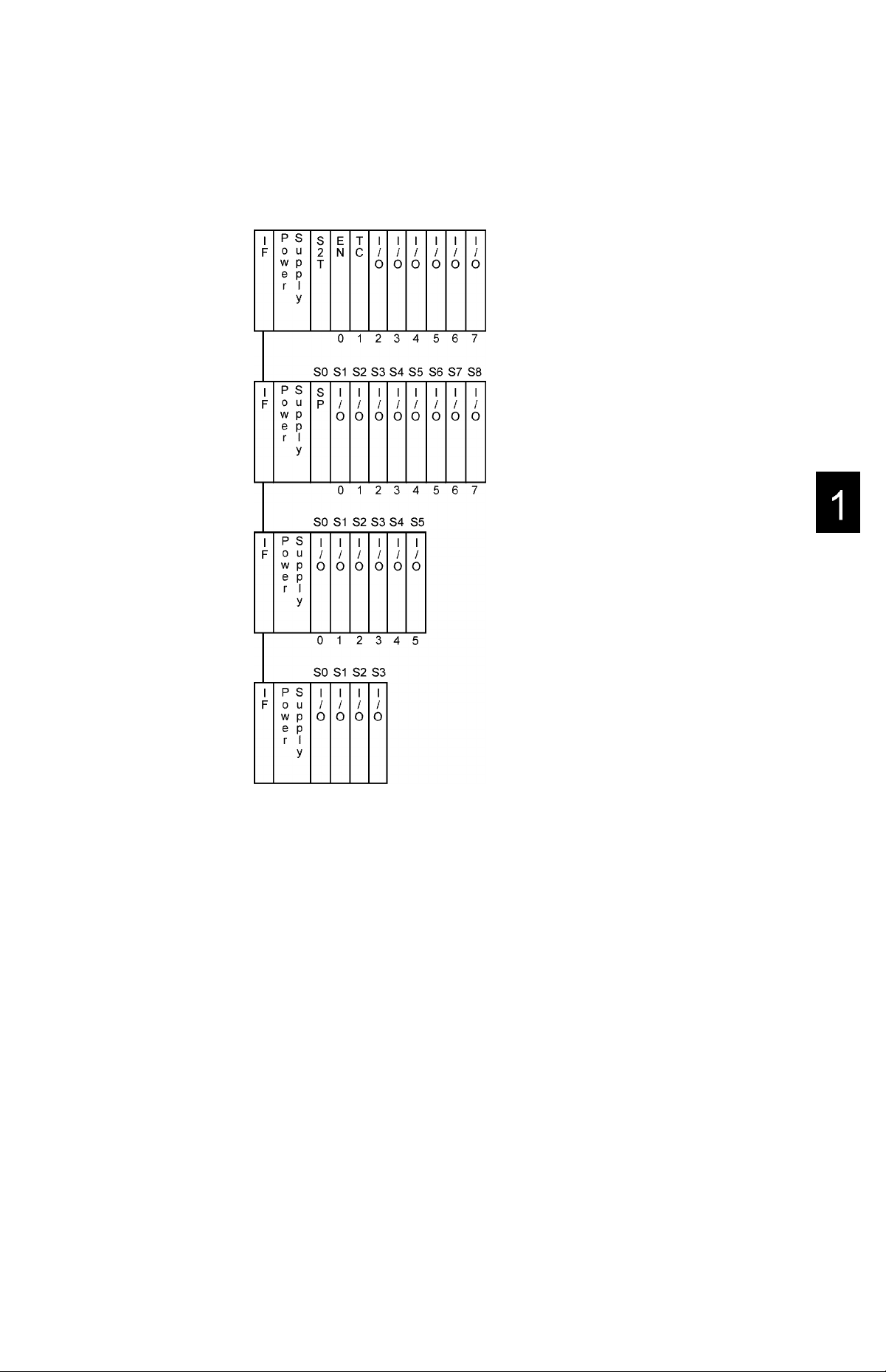
Chapt.1 System Configuration
The Integrated Controller Vseries has some features as mentioned before. The Sta
tion Module with station bus (internal high-speed data bus) interface can perform to
exchange common data between them on real time.
• Station Module
The Station Module is shown as below table. These can be mounted on the dedi
cated basic base and perform complex control combining each functionality.
Table1-1 S2TCPU
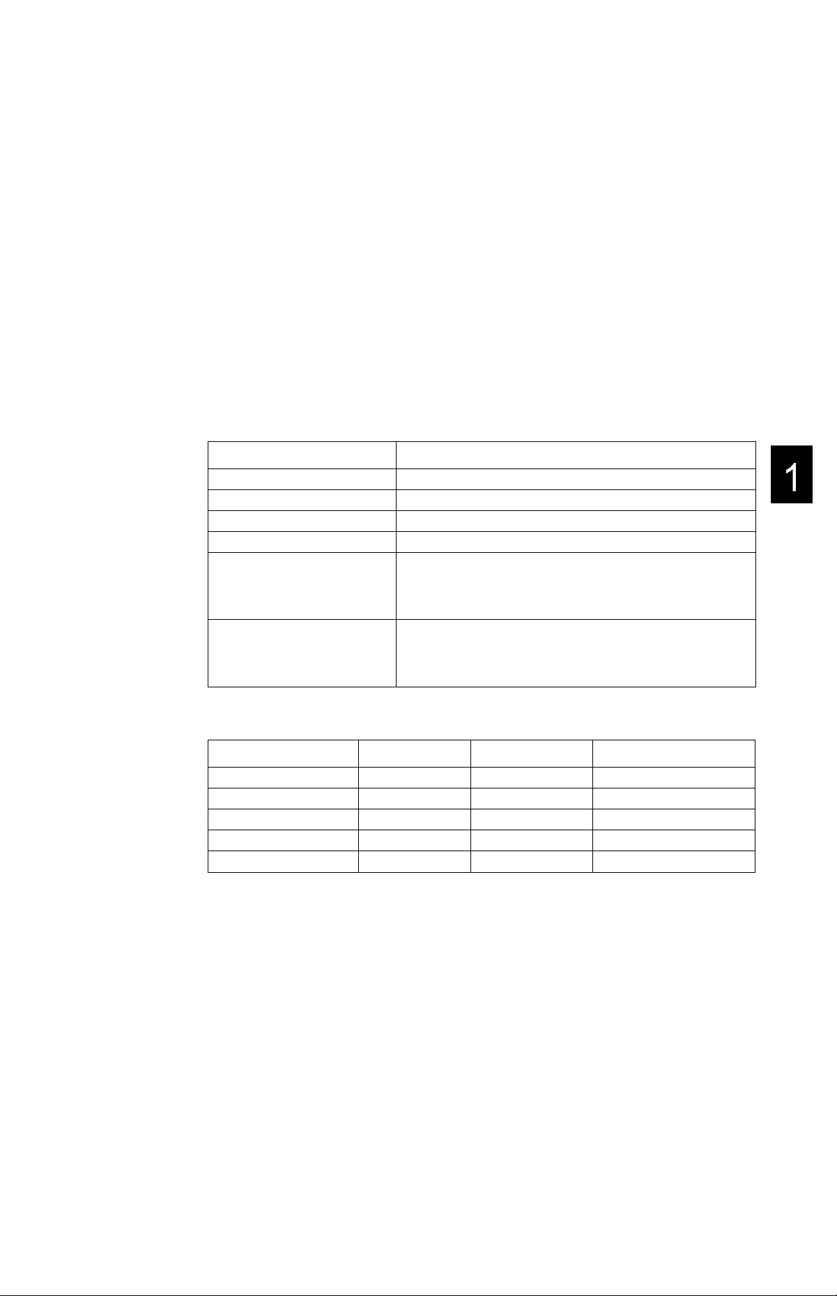
1
Description Specification
Sequence
Controller
Table1-2 Station Module
Item Description Specification
Controller
Network
*1: underdevelopment
*2: The above modules are performed on the main base with station bus.
Please refer to Section 1.1 or 1.3 for details of the ^stem configuration.
Sequence
Controller
Compute
Ethernet 10BASE5 EN611
TC-netIO 16KW, 10Mbps,co-axial CN611
TC-net20
32K-step
64K-step
32K-step
64K-step
WIndows-NT HDD
10BASE2
100BASE-TX, 10BASE-T
16KW, 10Mbps,co-axial. Double bus
16KW, 20Mbps,optical,Double Loop bus
PU662T
PU672T
Type
PU662T 1
PU672T 1
C2PU35
EN631
EN651
CN612
CN623*''
Type Remarks
No. of
Occupied slot
2
1
1
1
1
1
1
6F8C0926
Page 19
Chapt.1 System Configuration
1.1 S2T configuration as Station Module
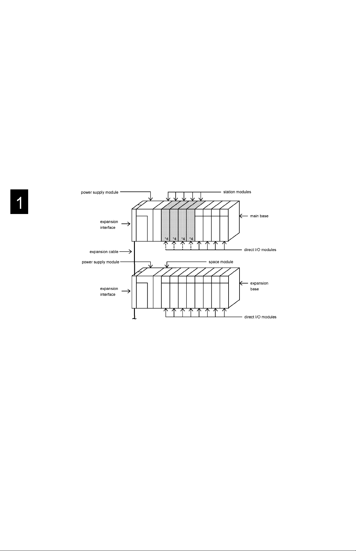
1.1.1 S2T basic configuration
According to variety of industrial applications, a basic unit or with expansion units are
selected.
The basic unit is composed of a main base, a power supply module, station modules
and direct I/O modules, and an expansion interface is added using expansion units.
The expansion unit is composed of an expansion base, a power supply module,
direct I/O modules and an expansion interface.
Each expansion interface modules are connected with expansion cables.
Up to three expansion units can be connected in the S2T.
The S2T accesses direct I/O modules via the G2-bus in the model 2000.
Basic unit
*4: The digital / analog I/O modules can be mounted in the *4 slots in place of the station modules.
Fig.1-1-1 An example of S2T basic configuration as station module
Expansion unit
Sequence Controller S2T
Page 20
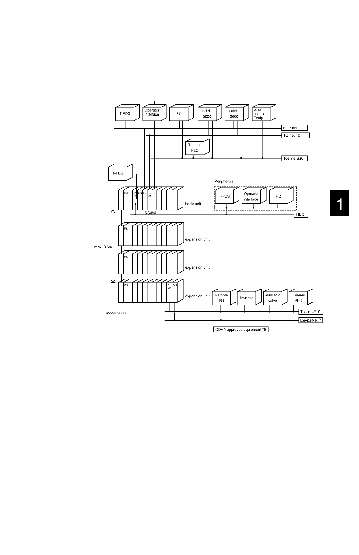
1.1.2 S2T System configuration
The S2T provide a functional, economical and compact solution to user applications
in automotive, machine control and process control, by using station modules and
direct I/O modules.
1.1 S2T configuration as Station Module
*5: DeviceNet is a registered trademark of the Open DeviceNet Vender Association, Inc.
Fig.1-1-2 An example of S2T system configuration as station module
6F8C0926
Page 21
Chapt.1 System Configuration
• Basic configuration
Base
Main base
Expansion base
Power supply module
100, 200Vac input PS691
100-240Vac input PS693
100-240Vac input
24Vdc input
tOOVdc input
S2T CPU module
32k-step
64k-step
Expansion interface
Standard IF661
Optional
Space module SP600
Unit cover SP601
Expansion cable for standard
0.3m
0.5m
0.7m CS6R7
1.2m
BU648E
BU643D
BU668
BU666
BU664
PS694
PS632
PS652
PU662T
PU672T
CS6R3
CS6R5
CS6*1
• station Module
Control module
Computer
Network module
TOSLINE-S20 SN625
TC-net10 CN611
TC-net20
Open Network module
Ethernet EN611
Serial, CompactFash interface
Serial, Compact
flash interface
C2PU35
SN626
SN627
CN612
CN623*''
EN631
EN651
CF612
•Software tool
Programming tool T-PDS
Windows-NT/98
(Japanese)
Windows-NT/98
(English)
TOSLINE-S20tool S-LS
Windows-/NT/98
(Japanese)
Windows-/NT/98
(English)
MW33J2
MW33E2
MW23J*
MW23E*
■1
• Direct I/O module
Digital input/output module
24Vdc input
100-120Vac input IN653
200-240Vac input IN663
Transistor output
(source type)
Triac output AC663
Relay output
Changect detect CD633
Analog input/output module
Analog input
Analog output
Serial interface
Serial interface CF611
DI632D
DI633
DI634
DI635
DI635H
DI653
D0633
D0634
D0635
D0633P
R0662S
R0663
AD624
AD674
AD628S
AD638S
AD668
RT614
TC618
DA622
DA672
DA664
*1: underdevelopment
*4: function limited
DDE server soft
Japanese Edition
English Edition PV33E2
Connecting cable
5m
PV33J2
CJ905
Network module
TOSLINE-S20
TOSLINE-F10 UN611
Network module
DeviceNet
FL-net FL611
Intelligent I/O module
Pulse input
Positioning control MC612
SN621*'’
SN622*“’
UN612
DN611A
FL612
PI632
PI672
MC614*''
Sequence Controller S2T
Page 22
1.1.3 Unitconfiguration
Some examples of minimum/maximum configuration are shown as below.
Basic unit
The main base dedicated for station module is used. The control module S2T should
be mounted on SO that is the left end slot of the base. Other station modules are
mounted on from S1 to S4 (BU648E) where two connectors are.
The digital/analog input/output module can be mounted on slots for station module.
These modules should be mounted on the right slot of station modules.
Table1-1-1 Main base
1.1 S2T configuration as Station Module
Type
BU648E For
Basic unit
BU643D For
Basic unit
Description
Slot No.
for station Module
5
4
3 6
2 7
1
4
3
2 2
1
Slot No.
for Direct I/O Module
Expansion unit
Table1-1-2 Expansion base
Type
BU668
BU666 0 6
BU664
Description
For
Expansion
unit
Space slot No.
1
0
Slot No.
for Direct I/O Module
Remarks
4
5
8
0
1
3
Remarks
8
4
6F8C0926
Module implementation from base view
Tablel-1 -3 Basic unit Module implementation
Slot
PIF
BU648E
BU643D
PS 0
- -
- - CPU
CPU
Tablel-1-4 Expansion unit Module implementation
PIF
BU668 - - X 10 10 10 10 10 10 10 10
BU666
BU664
- -
- -
PS 0
lO 10 10 10 10 10
lO 10 10 10
1 2
ALL ALL ALL ALL
ALL ALL ALL
1 2
3
Slot
3
4
4
5 6
10 10 10 10
5 6
7
7
8
8
Page 23
Chapt.1 System Configuration
PIF:Slot for expansion interface IF661
PS:Slot for power supply module
0 to 8:Slot number of base
CPU:Slot for CPU module S2T
IO:Slot for I/O module
AlhSlot for Station module,I/O module
Module implementation from each module view
Tablet-1-5 CPU module
NOTE
One module
occupied slot
PU672T 1
PU662T 1
C2PU35
2
BU648E BU643D
0 0
0 0 X X X
1 ''-3
S2T(PU672T,PU662T) used in Basic unit slot number "0".
Tablet-1-6 expansion interface
BU648E BU643D
IF661
Tablet-1-7 Network module
BU648E BU643D
EN651
EN611
EN631
SN625
SN626
SN627
UN611
UN612
DN611A
FL611
FL612
1 ~ 4
1 ~ 4
1 ~ 4
1 ~ 4
1 ~ 4
1 ~ 4
5~8
5 ~ 8
1 ~ 8
1 ~8
1 ~ 8
1 ~3
1 ~3
1 ~3
1 ~3
1 ~3
1 ~3
X
X
X
X
X
Slot
BU668 BU666
X X X
1 '^2
Slot
BU668 BU666
PIF
Slot
BU668 BU666
X X X
X X X
X X X
X X X
X X X
X X X
1 ~8 0 ~ 5 0~3
1 ~ 8 0 ~ 5 0 ~ 3
1 ~ 8 0 ~ 5 0 ~ 3
1 ~8 0 ~ 5 0~3
1 ~ 8 0 ~ 5 0 ~ 3
X X X
BU664
BU664
BU664
6
Sequence Controller S2T
Page 24

Table1-1-8 Direct I/O module, others
BU648E BU643D
DI632D
DI633
DI653
DI634
DI635
DI635H
I N653
I N663
D0633
D0633P
D0634
D0635
AC663
R0662S
R0663
CD633 *■'
AD624L
AD634L
AD624
AD674
AD628S
AD638S
AD668
TC618
RT614
DA622L
DA622
DA672
DA664
PI632 *■'
PI672 *■'
MC612
CF611
1 ~8
1 ~ 8
1 ~ 8
1 ~8
1 ~ 8
1 ~ 8
1 ~ 8
1 ~ 8
1 ~ 8
1 ~ 8
1 ~ 8
1 ~ 8
1 ~ 8
1 ~ 8
1 ~ 8
1 ~ 8
1 ~8
1 ~ 8
1 ~8
1 ~8
1 ~ 8
1 ~8
1 ~8
1 ~ 8
1 ~ 8
1 ~ 8
1 ~ 8
1 ~ 8
1 ~ 8
5~8
5~8
5~8
5 ~ 8
1.1 S2T configuration as Station Module
Slot
BU668 BU666
1 ~
3 1 ~8 0 ~ 5 0~3
1 ~
3 1 ~ 8 0 ~ 5 0 ~ 3
1 ~
3 1 ~ 8 0 ~ 5 0 ~ 3
1 ~
3 1 ~8 0 ~ 5 0~3
1 ~
3 1 ~ 8 0 ~ 5 0 ~ 3
1 ~
3 1 ~ 8 0 ~ 5 0 ~ 3
1 ~
3 1 ~ 8 0 ~ 5 0 ~ 3
1 ~
3 1 ~ 8 0 ~ 5 0 ~ 3
1 ~
3 1 ~ 8 0 ~ 5 0 ~ 3
1 ~
3 1 ~ 8 0 ~ 5 0 ~ 3
1 ~
3 1 ~ 8 0 ~ 5 0 ~ 3
1 ~
3 1 ~ 8 0 ~ 5 0 ~ 3
1 ~
3 1 ~ 8 0 ~ 5 0 ~ 3
1 ~
3 1 ~ 8 0 ~ 5 0 ~ 3
1 ~
3 1 ~ 8 0 ~ 5 0 ~ 3
1 ~
3 1 ~ 8 0 ~ 5 0 ~ 3
1 ~
3 1 ~8 0 ~ 5 0~3
1 ~
3 1 ~ 8 0 ~ 5 0 ~ 3
1 ~
3 1 ~8 0 ~ 5 0~3
1 ~
3 1 ~8 0 ~ 5 0~3
1 ~
3 1 ~ 8 0 ~ 5 0 ~ 3
1 ~
3 1 ~8 0 ~ 5 0~3
1 ~
3 1 ~8 0 ~ 5 0~3
1 ~
3 1 ~ 8 0 ~ 5 0 ~ 3
1 ~
3 1 ~ 8 0 ~ 5 0 ~ 3
1 ~
3 1 ~ 8 0 ~ 5 0 ~ 3
1 ~
3 1 ~ 8 0 ~ 5 0 ~ 3
1 ~
3 1 ~ 8 0 ~ 5 0 ~ 3
1 ~
3 1 ~ 8 0 ~ 5 0 ~ 3
X
X
X
X
1 ~8 0 ~ 5 0~3
1 ~8 0 ~ 5 0~3
1 ~8 0 ~ 5 0~3
1 ~ 8 0 ~ 5 0 ~ 3
BU664
6F8C0926
*1: When you use CD633, PI632, PI672 with interrupt function, implement in the Basic
unit in which S2T exists.
Page 25
Chapt.1 System Configuration
(1) Minimum Configuration
• Exampies of BU648E
so S1 S2 S3 S4 S5 S6 S7 S8 SO S1 S2 S3 S4 S5 S6 S7 S8
p
s
u
0
c
’
W
e
r
T
s
U
L
2
1
p T
S
p
2
0
y
0 1 2 3 4 5 6 7 0 1 2 3 4 5 6 7
E E T 1 1 1 1
N N
/ / / /
c
0 0 0 0
p
s
u
0
c
W
e
r
E T 1 1 1 1 1 1
s
U
p T
p
2 N
/ / / / / /
c
0 0 0 0 0 0
y
Main unit with 5 station moduies
and 4 i/0 moduies
UC*: unit cover
Exampies of BU643D
so SI S2 S3
P s
u
0 u
c
*
w p
e p
s
2 L 2 N
T
r 1
y
T
E
c
i
S
2
0
0 1 2 0 1 2
Using high performance
CPU, 4 siots
Main unit with 3 station moduies
and 6 i/0 moduies
so SI S2 S3
P s
U
0
C
w p
e p
s
U
2 L L /
T
r 1
y
T F 1
i
S
2
0
0
Using high performance
CPU, 2 siots
8
Sequence Controller S2T
Page 26
(2) Maximum Configuration
1.1 S2T configuration as Station Module
Number of I/O points (using 64-point I/O module)
SO S1 S2 S3 S4 S5 S6 S7 S8
Basic unit
Expansion unit
#1
Expansion unit
#2
384 points/BU648E
896 points/BU668
1,280 points/BU666
Expansion unit
#3
0 12 3
1,536 points/BU664
NOTE
IV.
The expansion interface should be mounted on each unit.
Two expansion connectors are fitted on the expansion interface. The upper side connector is
for input from previous unit and the lower side connector is for output to the next unit.
V. Up to a maximum of 3 expansion units can be connected.
vi. There is no limit on combinations of the types of the rack.
vii. Using BU668, the SO slot can’t be used and a space module SP600 should be mounted on SO.
The space module SP600 should be mounted on other vacant slots to avoid the risk of electri
cal shock.
6F8C0926
Page 27
Chapt.1 System Configuration
1.2 S2T CPU Module
1.2.1 Overview
The S2T CPU module performs user program, reading input data from the direct I/O
module and writing output data to the direct I/O module.
The S2T has two types of CPU modules.
Type
PU662T
PU672T
Program
language
Ladder +
SFC
Program
Capacity
32KS
64KS
Battery Memory
Built-in
RAM +
FlashROM
Expanded
memory
—
1MB
Link port
RS485
Built-in
When user program and parameter data are kept in the built-in flash ROM of the
S2T, user system will come back to be well quickly if any trouble occurs.
The S2T has the built-in two communication ports, one Programmer port and one
LINK port which is equipped for variety of peripherals, displays and PCs etc.
The front view of the S2T is shown as below. The operation mode switch, setting
switches of operation mode, status display LEDs are provided on the front panel.
Operation Mode Switch
(HALT, RUN)
Setting Switches
of Operation mode
PU672T
□
□
M
n
■ □
□
N
Ip
i
Status display LEDs
(RUN, FauLT, BATtery)
■ LINK port
Battery module cover
w
Programmer port
PROG
Fig.1-2-1 S2T CPU front view
10
Sequence Controller S2T
Page 28
1.2.2 Status display LEDs
These LEDs show operation states of the S2T.
Status display LEDs
1.2 S2T CPU Module
Name Display States
RUN (Green)
FLT (Red) Lit CPU abnormal or I/O abnormal
BAT (Green)
Lit
Blink HOLD Mode
Out Stopped state (HALT Mode) or Error Mode
Blink
Out Normal
Lit
Blink Battery caution
Out
1.2.3 Operation Mode Switch
The Operation Mode Switch is provided on the CPU module.
This switch controls S2T operation (RUN/HALT).
HALT-----------------Stop user program execution (HALT mode)
A
RUN -Start user program execution (RUN mode)
U
Remark
Operating state (RUN Mode)
CPU abnormal
Battery normal
Battery abnormal or no battery
CPU status is shown below after power up or after the operation mode is changed to
RUN from H
Setting
Position
HALT SW-1=OFF
RUN SW-1=OFF
ALT mode.
SW-1=ON
SW-1=ON
Initial Load Program
exe: executed
-: not executed
exe
exe
Operation
mode
HALT
RUN
-
Operation Mode
Change by the
Programming tool
Not available
available
As shown the above table, initial load (user program transfer from Flash ROM to
RAM) performs when setting SW-1 to OFF.
NOTE
i. The operation mode switch is set to HALT at the factory.
ii. Normally the programming is activated in the HALT mode,
ill. For details of the operation mode, see "S2T user's manual".
iv. The RAM is back-up by both internal capacitor and built-in battery of the S2T. When they go
down and the S2T can't keep retentive area in the RAM, CPU checks user program BCC.
CPU registers error if error is occurred.
6F8C0926 11
Page 29
Chapt.1 System Configuration
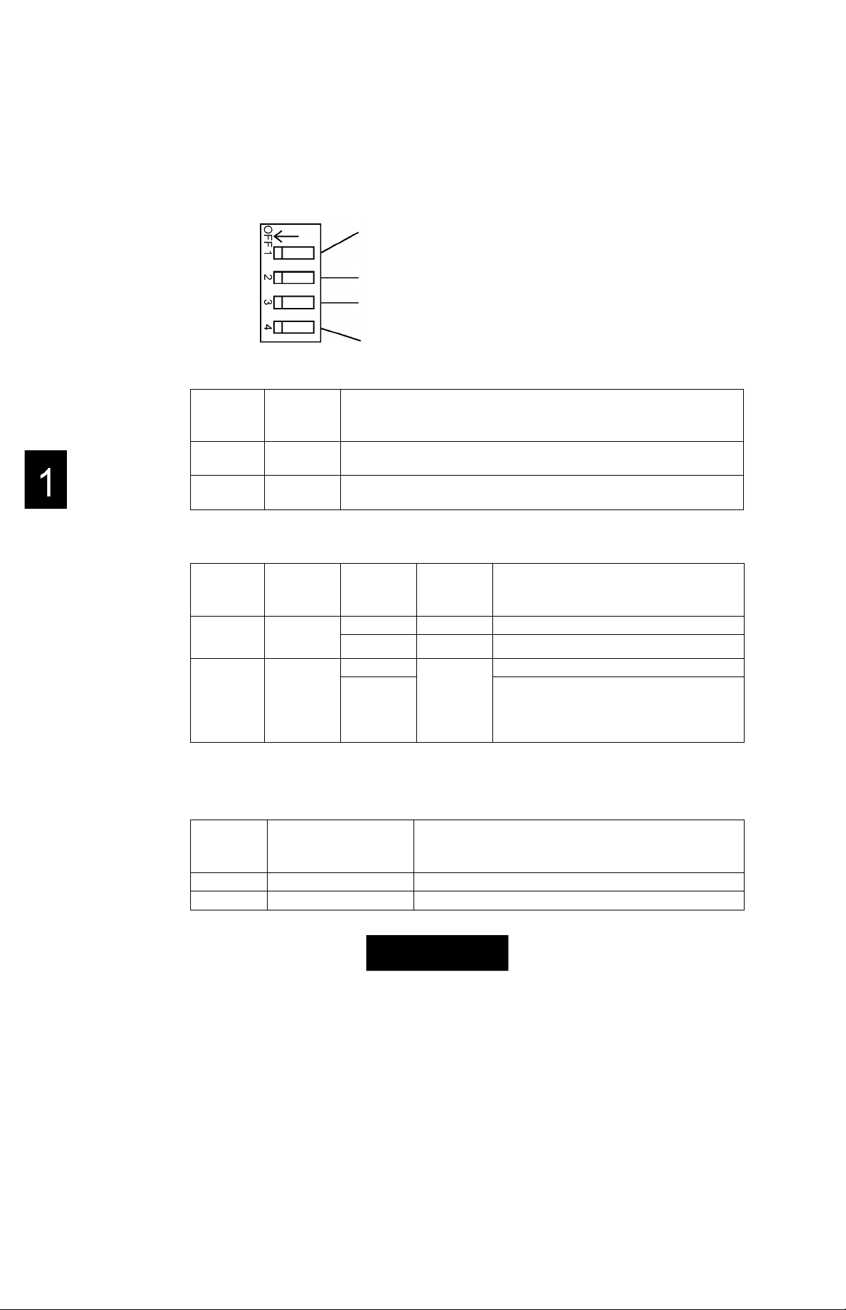
1.2.4 Setting Switches of Operation Mode
These switches are provided under the battery cover on the CPU front panei.
They controi the foiiowing fanctions. (SW-1 is ON, SW2, 3, 4 are set to OFF at the factory.)
SW-1 ROM/RAM Switch
Setting
Position
SW-1
OFF
ON RAM
Function
ROM Starts up after the content of the Flash ROM has been transferred to
the RAM. (Initial Load)
Starts up on the content of the RAM.
(No program transfer)
SW-2 RUN/Stand-by Switch
Setting
Position
SW-2
OFF
ON
Function
Automatic
RUN
Stand-by
. ROM/RAM Switch
_RUN/Stand-by Switch
•Programmer Port Parity :CPU reads this status oniy when power
Reserved (fixed to OFF)
at power up and at the beginning of the RUN mode
Operation
Mode
Switch
HALT HALT
RUN RUN
HALT HALT
RUN
Mode after
power up
:CPU reads this status when power is
changed from OFF to ON or when operation
mode is changed to RUN.
:CPU reads this status oniy when power
turns to ON.
turns to ON.
CPU operation
Remarks
Automatic RUN start occurs.
Starts up in the HALT mode. Ready to start
operation by an operate command from the
programming tool or by shifting the operation
mode switch.(^^LT^RUN)
is OFF, mode is set to Automatic RUN.
SW-3 Programmer Port Parity
Setting
Position
SW-3
OFF
ON
Odd Parity 8 bit Data, 9600bps, Data length is libit.
No Parity 8 bit Data, 9600bps, Data length is lObit.
Function
Remarks
<J>CAUTION
Mandatory
Set the switches of the CPU and I/O modules according to each instructions.
Mis-setting can cause malfunction or system accidents.
12 Sequence Controller S2T
Page 30
1.2.5 Programmer port of RS232C
The programmer (T-PDS) is connected to this programmer port.
Connector type of CPU side is female , 9-pin D-SUB connector.
The S2T’s RS232C programmer port can accept the computer link protocol (data
read/write). This results in easy connection to a higher level computer, an operator
interface unit, etc. directly.
General specifications and the connector pin assignment of programmer port are
shown below.
For details of T-series computer link protocol, see T-series User’s manual
- Computer Link (UM-TS03***-E008).
General specifications
1.2 S2T CPU Module
Item
Interface Conforms to RS232C
Configuration
Transmission distance 15m max.
Transmission speed
Frame format Start bit 1 bit
Supported command DR (Data Read)
One to One
9600bps (fixed)
Data 8bit
Parity odd/none (selected by SW.3)
stop bit 1 bit
DW (Data Write)
ST (Status read)
TS (Test text)
Pin assignment of programmer port
Signals No. of pins Symbols
Transmission data
Receive data
Signal ground 5 SO
Request To Send
Clear To Send 8 CTS
3
2 RXD S2T ^ Host
7
TXD S2T ^ Host
RTS
Specifications
Direction
S2T - Host
S2T ^ Host
S2T ^ Host
6F8C0926
NOTE
Other pins except the above table should not be connected.
13
Page 31

Chapt.1 System Configuration
1.2.6 LINK port of RS485
The S2T supports the following communication function mode on the LINK port.
Computer link mode
The computer link mode is used to connect between the S2T and a master computer
(included an operator interface, etc.).
By preparing the communication software based on the Toshiba’s computer link protocol
on the master computer, the following functions become available by the master
computer. The computer link protocol is a simple ASCII message communication
system.
Up to 32 S2T can be connected to a master computer on the RS-485 communication
line. (one-to-N configuration)
• Reading data (register/device value) from the S2T
• Writing data (register/device value) into the S2T
• Monitoring the S2T operation status (RUN/HALT/ERROR)
• Controlling the S2T operation mode (RUN/HALT)
The programmer can be connected to this link as a master computer.
One to N configuration
Master Computer
IRS232C/485 cqnyerterj
RS485(1km max.)
S2T S2T S2T
Fig.1-2-2 An example of computer link system configuration
• •
max.32
14 Sequence Controller S2T
Page 32

1.2 S2T CPU Module
Free ASCII mode
The free ASCII mode is used to connect between the S2T and various serial ASCII
devices, such as a micro computer, bar code reader, printer, display, etc.
By using this mode, the S2T can work as a communication master. Therefore, the
S2T can communicate with other PLCs using the computer link protocol, and can
control variable speed drives (such as Toshiba’s VF-S7) using its communication
protocol
S2T
Max. 32 devices
In this mode, user defined ASCII messages can be transmitted and/or received
through the link port of the S2T.
The ASCII message (one set of transmission characters) means a string of ASCII
characters which is ended by specified trailing code. The default setting of the trailing
code is CR (carriage return code = HOD)
Applicable message format (default trailing code):
1 2
3
4 N-1 N
CR
N: message length = 512 bytes max.
In other words, the S2T cannot be used for the data communication in which the
transmission message is ended by two or more types of trailing code.
6F8C0926
15
Page 33

Chapt.1 System Configuration
Transmission specifications
The communication parameter is set by writing it into the information memory of the
S2T with the programmer.
Tablel -2-1 Computer link mode
Item
Interface Conforms to RS-485 (4-wire system)
Transmission mode Half-duplex
Synchronizing
Transmission speed
Flame format Start bit 1 bit (fixed)
Protocol T-series computer protocol (ASCII),
Configuration One to N (32 max.)
Transmission distance 1 km max
Cable connection
Asynchronous
300, 600, 1200, 2400, 4800, 9600, 19200 bps
Data 7/8 bit
Parity even/odd/none
Stop bit 1/2 bit (NOTE)
T-series programmer protocol (Binary)
6-pin removable terminal block
Specifications
Table1-2-2 Free ASCII mode
Item
Interface Conforms to RS-485 (4-wire system)
Transmission mode Half-duplex
Synchronizing
Transmission speed
Flame format Start bit 1 bit (fixed)
Trans mission code ASCII
Message length
Configuration One to N (32 max.)
Transmission distance 1 km max
Cable connection
Asynchronous
300, 600, 1200, 2400, 4800, 9600, 19200 bps
Data 7/8 bit
Parity even/odd/none
Stop bit 1/2 bit (NOTE)
512 byfes max
6-pin removable terminal block
Specifications
16
NOTE
The following combinations of frame format are available.
Start bit
1 7 non 2
1 7
1 7
1
1
1
Data Length
8
8
8 even/odd
Parity Stop bit
even/odd
even/odd
non 1
non 2
Sequence Controller S2T
1
2
1
Page 34

Pin assignment of LiNK port
For details of wiring, see Section 1.3 or 1.4.
1.2 S2T CPU Module
Signals No. of pins Symbols
Transmission data A 1 TXA S2T^M aster
Transmission data B 2 TXB S2T^M aster
Receive data A 3
Receive data B 5
Termination Resistor 4 TERM
Signal ground 6 SG
RXA Master^S2T
RXB Master^S2T
Direction
—
—
6F8C0926 17
Page 35

Chapt.1 System Configuration
1.3 Computer link mode
1.3.1 Computer link function
In the computer link system, the S2T waits for receiving a request message issued
from the master computer.
When a request message is issued, the S2T checks the station number contained in
the request message. And when the station number designation matches the S2T’s
station number setting, the S2T processes the request and returns the response.
This is why each S2T must have a unique station number in the one-to-N
configuration. Otherwise, more than S2T’s may attempt to process the request,
resulting in faulty response.
The following figure illustrates the processing sequence when a request to station
number 3 is issued.
#1 #2
#3
#4
#5 #6
#7 #32
® The request message is sent from the master to all the connected S2T’s.
(request for station #3 in this example)
® The request message is interpreted and processed in the S2T which has the
same station number as request.
(station #3 S2T in this example)
® Processing result is returned as response to the master.
NOTE
Available station number is 1 to 32. The station number is set in the S2T’s system information
memory.
18
Sequence Controller S2T
Page 36

1.3 Computer link mode
Tablel-SSupplementary function for computer link
The following supplementary function are prepared for applying to various system
control using computer link function.
S2T
resister
Response delay mode on the
SW038
SW057
programmer port
(RS232C)
Response delay mode on the
LINK port (RS485)
1.3.2 System configuration
The following figure shows the system configuration using computer link function.
S2T, link port (RS-485), one-to-N configuration (N is max. 32) is available. If the
master computer has RS-232C interface only, the RS-232C/RS-485 converter (ADP6237B) can be used.
S2T, programmer port (RS-232C), one-to-one contiguration is available.
One-to-N configuration
(S2T: RS-485)
Master Computer
Name
Function
Setting value: 0-30
A response message is issued from the S2T after
(setting value *10) ms.
Setting value: 0-30
A response message is issued from the S2T after
(setting value *10) ms.
6F8C0926
Max. 32
One-to-one configuration
(S2T : RS-232C)
Master Computer
RS-232C
(15 m max.)
S2T
19
Page 37

Chapt.1 System Configuration
1.3.3 Setup procedure
The following chart shows the setup procedure of the computer link mode.
Connect the S2T to the master computer by RS-485
or RS-232C interface. Refer to section 1.3.4 or 1.3.5
Select the computer link mode by setting the SW
resister, Refer to section 1.3.6
Set the station number, baudrate, parity, data bit
length, and stop bit. Refer to section 1.3.7
Once writing into the EEPROM, the setting is
effective until change mode.
Refer to section 1.3.8 and the separate “T-series
Computer Link manual” for the computer link protocol
20
Sequence Controller S2T
Page 38

1.3.4 RS-485 cable connection
Cable connection examples show as below.
• Below figure shows an example of cable connection using the RS-232C/RS-485
converter (ADP-6237B).
• Use shielded twisted-pair cable for data communication suited to RS-485
standard. The cable shield should be connected to single -point ground.
One to one configuration
1.3 Computer link mode
Master
computer
RS-232C/RS-485 converter
(ADP-6237B)
connector block
S2T
S2T, removable terminal block is provided for cable connection.
Short between RXA and TERM for termination at both the S2T and the ADP-
6237B.
If the master has RS-485 (or RS-422) interface and the S2T is connected to the
master directly, connect termination resistor 1/2 W - 120 Q between RXA and
RXB at the master end.
6F8C0926 21
Page 39

Chapt.1 System Configuration
One to N configuration
RS-232C/RS485
converter
(ADP-6237B)
Shielded twisted-pair cable
Relaying
terminal
block
S2T
Termination
resistors
220 £5
S2T, removable terminal block is provided for cable connection.
Connect termination resistor 1/2 W - 220 Q. between RXA and RXB, and between
TXA and TXB at the both terminal stations.
Use shielded twisted-pair cable for data communication suited to RS-485
standard. The cable shield should be connected to single-point ground.
22 Sequence Controller S2T
Page 40

1.3.5 RS-232C cable connection
Cable connection examples show as below.
• Use shielded twisted-pair cable for data communication suited to RS-232C
standard. The cable shield should be connected to single -point ground.
1.3 Computer link mode
Master
computer
RXD
TXD
DTR
SG
DSR
RTS
CTS
Shielded twisted-pair cable
15 m max.
S2T
(RS-232C)
1
SG
2 RXD
TXD
3
4
5 SG
6 5 Vdc
7
RTS
8 CTS
9 5 Vdc
S2T, D-Sub 9-pin female connector is provided. Use D-Sub 9-pin male connector
as cable side.
RTS signal (pin 7) of the S2T is ON while power on.
CTS signal (pin 8) of the S2T has no mean on Communication control.
1.3.6 Mode setting
The operation mode of the S2T’s link port is selected by the special resister provided
on the S2T CPU module.
The operation mode is internally set at the timing of power-up. Setting changes while
power on is not effective.
To select the computer link mode, the special resister SW069 set to "0". (SW069=0)
At the factory, the computer link mode is selected.
S2T
resister
SW069
Name
link port operation mode 0: computer link mode
2: Free ASCII mode
Function
6F8C0926
23
Page 41

Chapt.1 System Configuration
1.3.7 Communication parameter setting
The communication parameter is set by writing it into the system information memory
of the S2T.
Turn the S2T to HALT mode, then set the communication parameter in the system
information.
(T-PDS screen example)
T-PDS32 for Windows - [UNTITLED] - Ma
F_ile Edit VieiAi Search PLC D.ebug Oommenl Option Windoyv idelp
«I malgjal
-laj
i-PLC Date & Time
Date:
System Comments:
¡=:^sTem =
OFFLINE
Memory Capacity:
PLC Version:
T-PDS Version:
Memory Size & Scan T'“c~ I Retentive Memory Area... | Computer Link... I
-------------
* ■ ■ ■ ^—' —- - ■ fc
Steps Used:
PLC Type:
64KS /8KW
0
S2T
T-PDS32 for Windows V2.1 4
____________________________
_____________________
After the communication parameter setting, write it into the S2T’s built-in EEPROM
before turning off power.
PC.:~n I
Wotfe ^
(T aian% r 'Smii
fiError Status & Diag. Msg.=
ErrorDiag. Msg. |
|rr;;;OK;.r;3 cancel | Help
----
------------------------------------------------------------------'
Comm Port: Baud Pate:
I ^
I“
: 1
Parity:
Data Bits:
Stop Bits:
96Ü0
Cdd
S
Set station number, baudrate, parity, data bit length,
and stop bit.
-¡g|
■-.M
24 Sequence Controller S2T
Page 42

1.3.8 Computer link protocol
This section introduces the general message format of the T-series computer link
protocol and the types of commands which are used for the S2T.
For details of the T-series computer link protocol, refer to the separate manual
"T-series Computer Link Operation Manuai".
Generai message format
1 2 3 4 5 6 7
( A ADR CMD DATA & SUM )/; CR
Checksum creation range
Text contents
1.3 Computer link mode
Max.255bytes
(
A Format identification code (FI41)
ADR
..........
Start code (H28) Ibyte
Ibyte
Station number
2byte
01 (H3031) through 32(H3332)
CMD
DATA
&
SUM
.........
........
..........
Command 2byte
Data field - depending on the command (max.244bytes)
Checksum delimiter (FI26)
Checksum
Ibyte
2byte
ASCII code of the lowest one byte of the sum obtained by
addingfrom the start code ’(’ to the checksum delimiter
See the following example.
)
?
..........................
End code (H29) Ibyte
End code (H3B)
Ibyte
in case of halfway of entire data
CR Carriage return code (FIOD) Ibyte
Checksum creation example:
A
(
1
0
T
s
& 9
7
CR
)
/\
= H28
■(’
‘A’ = H41
‘0’ = H30
‘1’
= H31
‘S’ = H53
‘T’ = H54
■&’ = H26
Lower two digits
HI 97-^ Sum
6F8C0926
25
Page 43

Chapt.1 System Configuration
List of computer link commands supported by the S2T
The following computer link commands are available for the S2T.
Request
command
-
-
TS Test Loop back test
ST
ER
DR
DW
MR
MW
SR System Info 1 Read Reads S2T’s system
S2
TR
RT Clock-calendar Read Reads clock-calendar data
WT Clock-calendar Write
EC PLC Control Changes S2T operation status
BR System Info Block
RB Program Block Read
CR Comment Block Read Reads S2T’s comments
BW System Information
WB Program Block Write
cw
Function name Description
Computer Link
Error Response
PLC Error Response The request command was
PLC Status Read
PLC Error Status Read Reads error code registered in
Data Read Reads registers/devices data
Data Write Writes registers/devices data
Expanded file register
data Read
Expanded file register
data Write
System Info 2 Read Reads S2T’s system
Diagnostic Message
Read
Read
Block Write
Comment Block Write Writes S2T’s comments
Format error was detected in
the request message
rejected by S2T
S2T returns the same text
Reads S2T operation status ST
the S2T
from the S2T
into the S2T
Reads the data in the expan
sion memory as expanded file
resister
Writes the data in the expan
sion memory as expanded file
resister
information 1
information 2
Reads user-defined error
information from the S2T
from the S2T
Writes clock-calendar data into
the S2T
Reads S2T’s system
information, block by block
Reads S2T’s program
block-by-block
block-by-block
Writes S2T’s system
information block-by-block
Writes S2T’s program
block-by-block
block-by-block
Response
command
CE
EE
TS
ER
DR
ST
MR
ST
SR
S2
TR
RT
ST
ST
BR
RB
CR
ST
ST
ST
Remarks
Response
only
Response
only
26
For details of the T-series computer link protocol, refer to the separate manual
"T-series Computer Link Operation Manual".
Sequence Controller S2T
Page 44

1.4 Free ASCII mode
1.4.1 Free ASCII communication function
The free ASCII mode is used to connect between the S2T and various serial ASCII
devices, such as a micro computer, bar code reader, printer, display, etc.
By using this mode, the S2T can work as a communication master. Therefore, the
S2T can communicate with other PLCs using the computer link protocol, and can
control variable speed drives (such as Toshiba’s VF-S7) using its communication
protocol.
In this mode, user defined ASCII messages can be transmitted and/or received
through the serial port of the S2T, link port (RS-485).
The ASCII message (one set of transmission characters) means a string of ASCII
characters which is ended by specified trailing code. The default setting of the trailing
code is CR (carriage return code = HOD).
Applicable message format (default trailing code):
1.4 Free ASCII mode
1 2
4 N-1 N
3
CR
N: message length = 512 bytes max.
In other words, the S2T cannot be used for the data communication in which the
transmission message is ended by two or more types of trailing code.
NOTE
The Free ASCII mode works as half-duplex communication system.
Therefore, simultaneous operation of transmitting and receiving is not possible.
6F8C0926 27
Page 45

Chapt.1 System Configuration
In the free ASCII mode, communication (message transmitting and receiving) is
controlled by S2T’s user program.
The expanded transfer (XFER) instruction is used for transmitting and receiving
messages.
Transmitting:
To transmit, the user prepares the message in the S2T registers in the format of
ASCII character. The message must be ended by a specified trailing code. Then
executes the XFER instruction to start transmission.
S2T
n n-1
CR
RS-485
„В”
“A”
Receiving:
When a message is received, it is stored in the receive buffer. Then, by using the
XFER instruction, the message is read and stored in the designated S2T registers in
the format of ASCII character.
S2T
Register
MSB LSB
“1" “0”
“3"
“5"
CR
“2"
“4"
“6”
XFER
instruction
Receiver
and
Receive
buffer
n-1 n
“6" CR
RS-485
28
The S2T supports the hexadecimal to ASCII conversion (FITOA) instruction and the
ASCII to hexadecimal conversion (ATOFI) instruction. These instructions are useful
to handle ASCII characters. Refer to sectioni .4.9.
Sequence Controller S2T
Page 46

1.4.2 System configuration
The following figure shows the system configuration using free ASCII communication
faction.
The S2T is connected to the serial ASCII device(s) through RS-485.
S2T
1.4 Free ASCII mode
Max. 32 devices
4or2 wire system selecting function (RS-485)
Either 4-wire system control or 2-wire system control can be selected in order to
connect various serial ASCII device(s) by using the following special function device.
S2T
resister
S688 RS-485
Wiring configuration
Name
OFF: 4-wire system
ON : 2-wire system(This function is available when
selecting 9600 or 19200bps.)
Function
6F8C0926
29
Page 47

Chapt.1 System Configuration
1.4.3 Setup procedure
The following chart shows the setup procedure of the free ASCII mode.
Connect the S2T to the serial ASCII devlce(s) by RS-485
interface. Refer to section 1.4.4
Select the free ASCII mode by setting the SW resister,
Refer to section 1.4.5
Set the baudrate, parity, data bit length, and stop bit.
Refer to section 1.4.6
Refer to section 1.4.8 for communication (transmitting
and receiving messages)
Once writing into the EEPROM, the setting is effective
until change mode
30
Sequence Controller S2T
Page 48

1.4.4 RS-485 cable connection
Cable connection examples show as below.
• Use shielded twisted-pair cable for data communication suited to RS-485
standard. The cable shield should be connected to single -point ground.
One to one configuration : 4-wire system
1.4 Free ASCII mode
S2T
____A......................
TXA
TXB RXB
RXA TXA
TERM
RXB TXB
SG SG
1 XX
>
ZD0(
Shielded twisted-pair cable
.......................................
Serial ASCII device
A
_____
RXA
1 ............................................................................................... 1/
1 km max.
R: 1/2 W-120 £2
• S2T, removable terminal block is provided for cable connection.
• Short between RXA and TERM for termination at the S2T.
• Connect termination resistor 1/2 W - 120 Q between RXA and RXB at the serial
ASCII device.
One to one configuration : 2-wire system
S2T
Shielded twisted-pair cable
Serial ASCII device
On the S2T, removable terminal block is provided for cable connection.
Short between RXA and TERM for termination at the S2T.
Connect termination resistor 1/2 W - 120 Q between RXA and RXB at the serial
ASCII device.
6F8C0926
31
Page 49

Chapt.1 System Configuration
One to N configuration : 4-wire system
S2T
Shielded twisted-pair cable
Serial ASCII device
220n
On the S2T, removable terminal block is provided for cable connection.
Connect termination resistor 1/2 W - 220 Q. between RXA and RXB, and between
TXA and TXB at the both terminal stations.
1.4.5 Modesetting
The operation mode of the S2T’s link port is selected by the special resister provided
on the S2T CPU module.
The operation mode is internally set at the timing of power-up. Setting changes while
power on is not effective.
To select the computer link mode, the special resister SW069 set to "2". (SW069=2)
At the factory, the computer link mode is selected.
S2T
resister
SW069
Name
link port operation mode 0: computer link mode
2: Free ASCII mode
Function
32 Sequence Controller S2T
Page 50

1.4.6 Communication parameter setting
The communication parameter is set by writing it into the system information memory
of the S2T.
Turn the S2T to HALT mode, then set the communication parameter in the system
information.
(T-PDS screen example)
1.4 Free ASCII mode
T-PDS32 for Windows - [UNTITLED] - Ma
File Edit View Search ^LO Debug Gamment Option WindodM jHelp
-¡g|
ilJ Stell g I a I
-laj
-PLC Date & Time
Date:
System Comments:
I
-----------------------
Memory Capacity 64KS / 8KW
Steps Used 0
PLC Type S2T
PLC Version
T-PDS Version T-PDS32 for Windows V2.14
Memory Size S Scan T'pr
OFFLINE
_________
| Retentive Memory Area... Computer Link...
After the communication parameter setting, write it into the S2T’s built-in EEPROM
before turning off power.
-Staf\:W6tie-
(* ^ncTfeiii c
:Error Status & Diag. Msg.^=
|C:r.g.KZT.51 cancel I
Set baudrate, parity, data bit length, and stop bit.
Station number is ignored.
Diag. Msg.
Comm Port: Baud Rate:
1 ^
■" r
Data Bits:
Stop Bits:
Parity:
96ÜQ
Cdd
S
J
■zi
6F8C0926
33
Page 51

Chapt.1 System Configuration
1.4.7 Message format
The transmission message is composed by ASCII characters and a specified trailing
code. The default setting of the trailing code is CR (carriage return code = HOD).
Refer to section 1.4.8 for setting the trailing code other than CR.
shown below.
The maximum length of a message is 512 bytes. An example of the message is
1 2
"1" "2" "A" "B" "7"
"0"
3
4
5 6
7
"8" "9" CR
8 9
In the above figure, "x" means an ASCII character. For example, "0" is H30.
The number (1 to 9) shown on each character means the order of transmitting or
receiving.
When the above message is received or transmitted, the data arrangements in the
S2T registers are as follows.
Transmission message
Register
n "1"
n+1 "A" "2"
n+2 "7" "B"
n+3
n+4
„g„
8 7
"0"
"8"
CR
CR
The message length is 1 byte, only trailing code, then receive operation ignore the
message.
34 Sequence Controller S2T
Page 52

1.4.8 Programming
(1) Changing the trailing code
The default setting of the trailing code is CR (carriage return code = HOD).
The trailing code can be changed by writing the desired code into SW068 at the
first scan.
SW068 HOO
Sample program:
(Sub-program 1)
14
2-[END 1
1.4 Free ASCII mode
8 7
New trailing code
(H0003)
GG0G3 MGU SUGGGT-
The above program is an example to change the trailing code to H03. The
new trailing code H0003 is written into SW068 in the sub-program 1 (initial
program).
(2) Data receive operation
When a message is received, it is stored in the receive buffer. The receive
buffer is a temporally memory, which has 512 bytes capacity. The expanded
transfer (XFER) instruction is used to read the message from the receive buffer
and to store it into user registers.
XFER instruction (message receive):
Input ^ ^ ^ER e ^ C J— Output
Operand A: Source
F__________________8 7
A HOO I
A+1 HOOOO
Operand 6: Parameter
F
В
B+1
B+2
Transfer length
Execution status
Receive message length (bytes)
H30
■ S2T link port (receiving)
■ 256 (256 words) fixed
<4
6F8C0926
Operand C: Destination register
F 8 7
C
C+1
HOO Register type
starting register address
-
---
-
Indirectly designated register
HOO: XWrrW
H01: W
H02: LW
H03: RW
H04: D
H05: F
35
Page 53

Chapt.1 System Configuration
Operation:
When the input condition of the XFER instruction comes ON, the read operation
is started. The execution status is monitored by B+1 as follows.
B+1 (Execution status): HOOOO ^ Normal complete
H0001 ^ Communication error (parity error, framing error)
H0002 ^ Message length over (more than 512 bytes)
H0003 ^ Receive buffer over flow
H0004 _ Receive time-out (see below)
The receive time-out is detected when the time from the starting character to the
trailing code exceeds the following time.
Long scan cyele or short receive message, low baudrate avoid the receive time-out.
Baudrate Time-out setting
300, 600, 1200 bps 30 seconds
2400 bps 15 seconds
4800 bps 7 seconds
9600 bps 3 seconds
19200 bps 1.5 seconds
Sample program:
00048 MOU D10001C 00000 MOU D1001T-
-C 00004 MOU D1002TC 01100 MOU D1003T-
- I-C 00Z56 MOU D10041C 00000 MOU D10051C 00000 MOU D1006]
R0100 R0101 R0102
Tf
---
T1—rC RST S00511CD1000 XFER D1004 ^ D1002]
SO051
—Li—T-CD1005 = 000001CD1006 <> 00000TC SET R0101>
H51005 <> 00000T-
S0051
R010O
—Ml
------
[ RST R0101TC RST R01021-
Rung 1: Sets the parameters for the XFER instruction.
The registers of 256 words starting with Dll00 are reserved to store
the received message.
Rung 2: When R0100 is set to ON, the read operation is started.
If the operation is completed normally, the received message is
stored in D1100 and after, and R0101 is set to ON.
If the message could not be received normally by some error, R0102
is set to ON.
-[SET R0102T-
--------------------------------------
-------------------------
36
Rung 3: When R0100 is reset to OFF, the result status (R0101 and R0102)
are reset to OFF.
Sequence Controller S2T
Page 54

1.4 Free ASCII mode
When using the above sample program as a part of entire application program,
set R0100 to ON in the main processing part at first. When a message is
received, R0101 (at normal) or R0102 (at error) comes ON. Then reset R0100
and carry out necessary processing for the received message. When the result
status shows normal complete (R0101 is ON), the received message has been
stored in D1100 and after.
When it becomes ready to receive the next message, set R0100 to ON again.
(3) Data send operation
The expanded transfer (XFER) instruction is used to send the message through
the optional communication card.
XFER instruction (message send):
Input ^ ^ ^ER e ^ C J— Output
Operand k. Source register
Д
Д+i
8 7
HOO Register type
Starting register address
-
---
-
Indirectly designated register
HOO: XWrrW
H01: W
H02: LW
H03: RW
H04: D
H05: F
Operand B: Parameter
F 0
в
B+1
Transfer length
Execution status
<T-
■ 1 to 256 words
Operand C: Destination
F 8 7 0
c
C+1 HOOOO
HOO H30
- S2T link port (sending)
Operation:
When the input condition of the XFER instruction comes ON, the message
prepared in the registers starting with A is transmitted.
The execution status is monitored by B+1 as follows.
B+1 (Execution status): FIOOOO ^ Normal complete
FI0001 ^ During transmitting the message
FI0002 _ Communication busy (other receiving or
transmitting routine is under executing)
FI0003 ^ During the reset operation
FI0004 ^ Send time-out (see below)
FI0005 ^ Send message length error
(no trailing code in the source table)
6F8C0926 37
Page 55

Chapt.1 System Configuration
The send time-out is detected when the time from the starting character to the
trailing code exceeds the following time.
Long scan time or short send message, low baudrate avoid the send time-out.
Baudrate Time-out setting
300, 600, 1200 bps 30 seconds
2400 bps 15 seconds
4800 bps 7 seconds
9600 bps 3 seconds
19200 bps 1.5 seconds
Sample program:
Rung 1: Sets the parameters for the XFER instruction.
The registers of 256 words starting with D1500 are reserved to store
the transmitting message.
Rung 2: When R0200 is set to ON, the message stored in the D1500 and after
are transmitted.
If the operation is completed normally, R0201 is set to ON.
If some error has occurred during the operation, R0202 is set to ON.
Rung 3: When R0200 is reset to OFF, the result status (R0201 and R0202)
are reset to OFF.
When using the above sample program as a part of entire application program, write
the transmitting message (including the trailing code) in D1500 and after, and set
R0200 to ON in the main processing part. By this operation, message transmitting is
started. When the message transmitting is completed, R0201 (at normal) or R0202
(at error) comes ON. Confirm these result status and reset R0200 to OFF.
While a message is transmitting, do not change the contents of the transmitting
message which has been set in D1500 and after.
38
Sequence Controller S2T
Page 56

1.4 Free ASCII mode
(4) Reset operation
By setting S068F to ON, resetting the free ASCII mode operation is available.
During the reset, the following re-initialization is processed.
• Initializes the serial port (RS-485)
• Initializes the receive buffer and the receive error information
• Resets the trailing code based on the data of lower byte of SW068
When the reset operation is completed, S068F is automatically reset to OFF.
The free ASCII mode operation should be re-started after confirming S068F is
returned to OFF.
NOTE
If S068F is set to ON during a message receiving, the reset operation is started after the
message receiving is finished.
6F8C0926
39
Page 57

Chapt.1 System Configuration
1.4.9 Related instruction
(1) Expanded data transfer (XFER)
FUN 236 XFER
Expanded data transfer
Expression
Function
When the input is ON, data block transfer is performed between the source
which is indirectly designated by A and >A+i and the destination which is
indirectly designated by C and C+1 The transfer size (number of words) is
designated by B.
The transfer size is 1 to 256 words, (except for writing into EEPROM)
Data transfer between the following objects are available.
• CPU register ^ CPU register
• CPU register ^ Expanded F register (S2T’s internal memory)
• CPU register ^ TOSLINE-S20 (here called S20, for S2T)/
TOSLINE-S20LP(here called S20LP, for S2T)
• CPU register ^ EEPROM (D register)
Source
/A
parameter
Transfer
B
size
Destination
C
parameter
Name
• CPU register ^ S2T link port
Execution condition
Input
OFF No execution OFF
ON Normal execution ON
When error is occurred (see Note)
Operand
Device
X Y
L R Z T.
S
c.
Operation
Register
I
X Y
0
W W w w w w w
V V V V V V V V V V V
V V V V V V V V V V V
L R w T
s
V V V V V V V V V V
c
D F I
Output
ON
I
0
J
ERF
-
-
Set
Con
start
Index
K
40
Sequence Controller S2T
Page 58

1.4 Free ASCII mode
A+1
/A
Source parameter
Bank/CH
Leading address B+1
Type
Refer to the following table for contents of each designation.
The status flag is created when S20 is designated as transfer source or S2T
is designated as source/destination.
Transfer size and status
B Transfer size
Status flag C+1
(max. 16 words)
B+16
Destination parameter
Bank/CH
C
Leading address
Type
6F8C0926 41
Page 59

Chapt.1 System Configuration
Transfer parameter table
Transfer object Bank/CH TYPE Leading address Transfer size
XWATA/ register
W register
LW register
u.
0)
w
RW register
'u)
0)
u.
3
CL
O
D register
F register
Expanded F register
(1C memory card)
Expanded F register
(T2E/S2T
internal memory)
TOSLINE-S20
scan memory
TOSLINE-S20LP
scan memory
EEPROM (D register)
T2E communication
card / T2N / S2T link port
Global variable
0 HOO 0 to 511 (T3H/S2T)
0 to 255 (T3)
0 to 63 (T2/T2E)
0 H01
0
0 H03 0 to 999 (T3H/S2T)
0
0 H05
1 to 15
(T3H/T3/T2)
1 or 2 (T3H)
1 to 3 (T2E)
1 to 15(S2T)
1 to 8 (S2T) H06 0 to 65535 (Bank 1 to 7)
1 or 2
(T3H/T3/S2T)
1 (T2/T2E)
1 or 2 (T3H/S2T)
1 (T2N)
0 H20
0 H30 0
0 to 7 (S2T)
H02
H04
H05 0 to 8191 1 to 256 None
H06 0 to 65535 (Bank 1)
H05 0 to 8191 1 to 256 None
H10 0 to 1023 (S20) 1 to 256
H10 0 to 4095 (S20LP) 1 to 256
H51 0 to 16383 (TC-net)
0 to 2047 (T3H/T2N/S2T)
0 to 1023(T3/T2/T2E)
0 to 255
(T3H/T3/T2/T2E/T2N/S2T)
0 to 511 (T3)
0 to 255 (T2N)
0 to 127 (T2/T2E)
0to63(T1)
0 to 8191
(T3H/T3/T2N/S2T)
0 to 4095 (T2/T2E)
oto 1023(T1)
0 to 32767 (T3H/S2T)
0 to 8191 (T3)
0 to 1023 (T2/T2E/T2N)
0 to 57343 (Bank 2)
0 to 57343 (Bank 8)
0 to 8191 (T3H/T3/S2T)
0 to 4095 (T2/T2E/T2N)
0 to 511 (T1)
0 to 32767 (C2)
1 to 256
1 to 64
1 to 256 None
1 to 256 None
1 to 256
1 to 128
1 to64(T1)
1 to 256 None
1 to 256 None
1 to 256 None
1 to 256 None
Source (read):
1 to 256
Destination (write):
1 to 128 (T3H/S2T)
1 to 64 (T3)
1 to 32
1 to 16 (T1)
1 to 256 *2 Yes
1 to 256 None
Status
flag
None
(T3H/T3/S2T)
(T2/T2E/T2N)
None
(T3H/T3/S2T)
(T2/T2E/T2N)
Yes
Yes
None
(T2/T2E/T2N)
*1) When S20 is transfer source, the scan healthy map is created, (max. 16 words)
In case of S20LP, no status flag is added.
*2) When the link port is transfer source (receiving), the transfer size must be 256 (fixed).
*3) When the link port is transfer source (receiving), 2 words of status flag is added.
When it is destination (transmitting), 1 word of status flag is added.
*4) PU672T has the expansion memory, and use 512k words expanded file resister.
PU662T don’t have the expansion memory, so this function can’t be used.
42 Sequence Controller S2T
Page 60

1.4 Free ASCII mode
CPU register o S2T link port
<Receiving>
Operation:
When the instruction input is ON, one set of message (from start character to
the trailing code) which is received by the link port is read from the receive
buffer, and stored in the CPU registers. The transfer size is fixed to 256
words. The execution status and the message length (in bytes) are stored in
the status flag.
The instruction input must be kept ON until the receiving operation is
complete.
Example:
Source designation Transfer size Destination designation
DOOOO
D0001
HOO H30
00000 D0003
Link port
D0002
D0004
00256 (fixed) D0005 HOO
Execution status
Message length
D0006 00100 1
D0100 (CPU register)
H04 1
When ROOOO is ON, one set of received message is read and stored in
D0100 and after.
Execution status: HOOOO .
H0001 .
H0002 .
H0003 .
H0004 .
Message length: 0
.........................
.. Normal complete
.. Communication error (parity error, framing error)
.. Message length over (more than 512 bytes)
.. Receive buffer over flow
.. Receive timeout (from start character to the trailing code)
Baudrate Time-out setting
300, 600, 1200 bps 30 seconds
2400 bps 15 seconds
4800 bps 7 seconds
9600 bps 3 seconds
19200 bps 1.5 seconds
No receive message
1 to 512 ... Message length in bytes
Remarks:
The instruction error flag (S0051) comes ON in the following cases, (no
operation)
• The leading address for the link port designation is other than 0.
6F8C0926
• Transfer size is other than 256.
• Mode setting of the link port is not the free ASCII mode.
• This instruction is programmed in the sub-program #1.
43
Page 61

Chapt.1 System Configuration
D0010 HOO
D0011 00500 D0013
<Transmitting>
Operation:
When the instruction input is ON, one set of message which is stored in the
source table (from start character to the trailing code) is transmitted through
the link port. The execution status is stored in the status flag.
The instruction input must be kept ON until the transmitting operation is
complete.
Example:
Source designation Transfer size Destination designation
H04 D0012 00012
Execution status
D0015 HOO H30
D0016 00000
D0500 (CPU register)
Link port
When R0001 is ON, one set of message (ended by the trailing code) stored in
the range of D0500 to D0511 (12 words) is transmitted through the link port.
Execution status: HOOOO ... Normal complete
H0001 ... During transmitting the message
H0002 ... Communication busy (other receiving/transmitting
routine is executing)
H0003 ... During the reset operation
H0004 ... Send time-out (from start character to the trailing code)
H0005 ... Send message length error (no trailing code in the source
table)
Baudrate Time-out setting
300, 600, 1200 bps 30 seconds
2400 bps 15 seconds
4800 bps 7 seconds
9600 bps 3 seconds
19200 bps 1.5 seconds
Remarks:
The instruction error flag (S0051) comes ON in the following cases, (no
operation)
• The leading address for the link port designation is other than 0.
• Transfer size is out of the range of 1 to 256.
• Mode setting of the link port is not the free ASCII mode.
• This instruction is programmed in the sub-program #1.
44 Sequence Controller S2T
Page 62

1.4 Free ASCII mode
(2) HEX to ASCII conversion (HTOA)
FUN 62 HTOA HEX to ASCII conversion
Expression
Input —^ ^ ^TOA (n) B ]— Output
Function
When the input is ON, the hexadecimal data of n registers starting with A is
converted to the ASCII characters and stored in B and after.
The uppermost digit of source A is stored in lower byte of destination 6, and
followed in this order.
The allowable range of n is 1 to 32.
When index or constant value is set as source A., this function can be
performed under the condition that n is equal to 1. If n is more than 1, a
boundary error is occured.
Name
A
Source
n
Size
B Destination
X Y
Execution condition
Input
OFF No execution OFF
ON Normal execution ON
Operation
Operand
Register
c
D F I
0
L R Z T.
S
Device
c.
I
X Y
0
W W w W W w w
V V V V V V V V V V V V V V V V
L R w T
s
V V V V V V V V V V V
Exampie
Output
Con
I
K
J
stant
1 -32
Index
6F8C0926
When R0010 is ON, 4 words data of RW100 to RW103 are converted into ASCII
characters, and stored in 8 words registers starting with D0220.
45
Page 63

Chapt.1 System Configuration
RW100 HOI 23 D0220 “1” (H31) “0” (H30)
RW101 H4567 Converted D0221 “3” (H33) “2” (H32)
RW102 H89AB ^ D0222 “5” (H35) “4" (H34)
RW103 HCDEF D0223 “7” (H37) “6” (H36)
(3) ASCII to HEX conversion (ATOM)
F 0 F 8 7 0
D0224 “9” (H39) “8” (H38)
D0225 “B” (H42) “A” (H41)
D0226 “D” (H44) “C” (H43)
D0227 “F” (H46) “E” (H45)
FUN 66
ATOH ASCII to HEX conversion
Expression
Function
When the input is ON, the ASCII characters stored in n registers starting with A
is converted to the hexadecimal data and stored in В and after.
The lower byte of source A is stored as uppermost digit of destination 6, and
followed in this order.
The allowable ASCII character in the source table is "0" (H30) to "9" (H39) and
"A" (H41)to "F" (H46).
The allowable range of n is 1 to 64.
When index or constant value is set as source A., this function can be
performed under the condition that n is equal to 1. If n is more than 1, a
boundary error is occured.
Execution condition
Input
OFF No execution OFF -
ON Normal execution ON
Conversion data error (no execution) OFF ON
Operation
Output
Operand
Device
Name
/А
Source V V V V V V V V V V V V V V V V
n
Size
в Destination
X Y
L R Z T.
S
c.
1
X Y
0
W W w W W w w
L R w T
s
V V V V V V V V V V V
46
Register
c
D F 1
1
0
к
J
Sequence Controller S2T
Con
start
1 -64
ERF
-
Index
Page 64

1.4 Free ASCII mode
Example
When R0021 is ON, the ASCII characters stored in 8 words of D0300 to D0307
are converted into hexadecimal data, and stored in 4 words registers starting
with RW110.
8 7
D0300
D0301
D0302
D0303
D0304
D0305
D0306
D0307
“1” (H31) “0” (H30)
“3” (H33) “2” (H32)
“5” (H35) “4” (H34)
“7” (H37) “6” (H36)
“9” (H39) “8” (H38)
“B” (H42) “A” (H41)
“D” (H44) “C” (H43)
“F” (H46) “E” (H45)
Converted
RW110
RW111
RW112
RW113
HOI 23
H4567
H89AB
HCDEF
If the source table (D0300 to D0307) contains invalid characters (other than "0"
to "F"), the instruction is not executed and the output (R0022) stays OFF.
If the word number of conversion is odd, the lower 2 digits of last data on the
destination table is unknown.
Therefore set even value to the word number of conversion.
6F8C0926 47
Page 65

Chapt.1 System Configuration
1.4.10 Sampleprograms
A. Variable speed drive (Toshiba’s VF-S7) control
A sample program for the S2T to control the variable speed drive, VF-S7, is shown
here.
For details of the serial communication function of the VF-S7, read the separate
manual “VF-S7 Serial Communication Function”.
(1) Link port setting
a) Mode setting of the Link port (S2T):
Select the free ASCII mode by setting the SW069 to "2"
b) Communication parameter setting:
Set the S2T’s communication parameters (baudrate, data bit length, parity and
stop bit length) to be matched the VF-S7’s setting.
The VF-S7’s setting at factory shipment is as follows.
The S2T’s stop bit length should be set to 1 bit.
Baudrate: 9600 bps (changeable)
Data bits: 8 bits (fixed)
Parity: Odd (changeable)
c) Communication time-out setting of VF-S7:
To let trip the VF-S7 at the case of communication error, enable the time-out
function of the VF-S7. To do this, set the monitor time on the VF-S7’s
parameter F803.
In this sample program, the VF-S7’s operation (start and stop) is controlled
through the serial communication. Flowever, for actual application, it is
recommended to use the terminal inputs for the signals F (forward) and R
(reverse) even if the frequency is controlled through the serial communication.
(2) Communication commands used in this sample program
In this sample program, the following commands (function numbers) are used.
The VF-S7’s station number is assumed as 01.
FE01 Operation status (read)
FAOO Control command (write) - forward / reverse / stop / reset
FA01 Operation frequency (write)
48
Sequence Controller S2T
Page 66

(3) S2T sample program
In this sample program, the following devices/registers are assigned.
1.4 Free ASCII mode
D0015
ROOOO
R0001
R0019
Operation frequency (0 to 6000, 0.01 Hz increments)
Forward command (ON for start / OFF for stop)
Reverse command (ON for start / OFF for stop)
Status (forward: OFF / reverse: ON)
R001A: Status (stop: OFF / run: ON)
MAIN PROGRAM BLOCK 1
-n
[ 00004 MOV DOOOO][ 00010 MOV DOOOl][ 00048 MOV D0002][ 00000 MOV D0003]
[ 00007 MOV D0004][ 00000 MOV D0005]
[ 00004 MOV DOOlO][ 00040 MOV DOOll]
[ 00256 MOV D0012][ 00000 MOV D0013][ 00000 MOV D0014]
[D0015 <> D0016][D0015 MOV D0016]
ROOOO
-|P| —[' (01PFA00C400)
ROOOl
-|P| —[' (01PFA00C600)
ROOOO
- INI-+[' (OIPFAOOCOOO)
ROOOlI
- I N I -+
R0003
- IPI-+[' (OIPFAOOEOOO)
ROOOFI
-1 p I -+
ASC D0020]-
ASC D0020]-
ASC D0020]-
ASC D0020]-
[MCS ]
[MCR ]
R0002
- ( ) —
Initialize
Parameter setting for
XFER (send)
Parameter setting for
XFER (receive)
Change detect of
frequency designation
(D0015)
Send message create
(Station 01)
Command (FAOO)
Following commands are
used
“C400”: Fonward
“C600”: Reverse
“COOO”: Stop
“EOOO”: Reset
R0002
-I I-+['(OIPFAOIOOOO)
+[D0015 HTOA (01) D0024]-
[]
---
[HODOO OR D0026 -> D0026] [ SET ROOOD] [ 00020 MOV D0017]
6F8C0926
ASC D0020]-
Operation frequency
(FA01)
Converts hex data of
D0015 into ASCII
Adds trailing code (HOD)
49
Page 67

Chapt.1 System Configuration
ROOOD T.OOO
-l/l — l/l —[00060 TON TOOO] [' (OlRFEOl) ASC D0030]
[]
---
[HODOO OR D0034 -> D0034] [ SET ROOOE] [ 00030 MOV D0017]
ROOOE ROOOD
10
-l/l — I I------n-+[D0017 MOV DOOOl] [ SET ROOOA] ■
T.OOO
-IPI
-------------
ROOOA
11
-I |-+[D0000 XFER D0004 -> D0002]
+ [D0005 = 00001]-|v| —[ RST ROOOA]
ROOOA
12
-|/|-+[D0002 XFER D0012 -> DOOlO]
S0051
+-I/I —[D0014 <> 00000]
R0009 ROOOD
13
-I I —I I —[D0020
[]
---
[D0024 = D0044] [D0025 = D0045] [ RST ROOOD] [ RST R0003]
+
D0040][D0022 = D0042][D0023 = D0043]
R0009
- ( ) —
----------
Message for Status read
Address FE01 read
Adds trailing code (HOD)
Message send timing
create
Message send
Message receive
Received message check
for Command
R0009 ROOOE
14
-I I —I I —[D0030 = D0040] [D0032 = D0042] [D0033 = D0043] []
[]
---
[ RST ROOOE] [D0044 ATOH (02) RWOOl] [D0041 AND HFFOO -> D0039]
ROOOD
-I I-+[00300 TON TOOl] [ RST ROOOD] [ RST ROOOE] [ RST ROOOA]-
15
ROOOEIROOOE
-I I-+-I I —[D0039
ROOOF
16
-I I —[ 00000 MOV D0015] [ RST ROOOO] [ RST ROOOl]
17
[END ]
29184]
-+-( )
ROOOF
Received message check
for Status read
Timing create for Reset
command
Flags and frequency data
clear for Reset command
50
Sequence Controller S2T
Page 68

1.5 Units
1.5.1 Bases
1.5 Units
As mentioned in Section 1.1, the basic unit of the model 2000 is composed of a main
base, a power supply module, a S2T CPU module.
The expansion interface is added to the main base depending on I/O modules
required.
The expansion interface should be mounted on each base and are connected with
expansion cables. Set the unit No. (called unit address) before operating. The unit
address is set by a rotary switch in the middle of the expansion interface.
The base has two kinds of type bases, for dedicated to the basic unit and for
expansion unit.
For details of unit configuration, see Section 1.1.3
Tablel -5-1 Number of direct I/O module installation
Type
BU648E
BU643D
BU668
BU666
BU664 For expansion unit 4
Description
For basic unit 8
For basic unit 3
For expansion unit
For expansion unit
Direct I/O Module Remarks
BU648E
BU643D
8
6
6F8C0926
>
IH E
P?l P5I
El El El E
pm
51
Page 69

Chapt.1 System Configuration
• BU668
BU666
BU664
52 Sequence Controller S2T
Page 70

1.5.2 Expansion interface
The expansion interface IF661 is mounted on the left side slot of base to expand
bases after removing the unit cover. Set the unit No. (called unit address) before
operating. The unit address is set by a rotary switch in the middle of the expansion
interface removed the cover.
Setting the unit No.
The rotary switch to set unit address is provided between two expansion connectors.
The upper side connector is for input from previous unit and the lower side connector
is for output to the next unit.
1.5 Units
Mounted on
Basic unit 0
Expansion unit
NOTE
i) Switches will be set to 0 at the factory.
ii) Be careful not to duplicate unit Nos. on units.
iii) Do not use setting 4 - 9, as these are not for use.
1.5.3 Expansion cables
These are used for connecting the basic unit and the expansion units.
They are available in the following four lengths.
Type
CS6R3
CS6R5
CS6R7 70cm
CS6*1
Switch setting
1,2,3 Set in order to 1>2>3, starting from the unit
closest to the basic unit.
Length
30cm
50cm
1.2m
Remarks
Remarks
6F8C0926
NOTE
The maximum cable length between units is 1.2m.
The maximum total cable length is 3.6m.
53
Page 71

Chapt.1 System Configuration
1.6 Power Supply Module
Power supply modules are mounted on the second slots from the left-end of all
bases.
There are two types according the power voltage and total power. Select one as
required.
Configure the system, referring to the module current consumption table in the
Section 1.18.2, so that the following equation is satisfied.
Maximum power consumption > 5V * Total 5V current + 3.3V * Total 3.3V current
1.6.1 Power Supply Module
There are t hree type modules as follows.
Type
PS691
PS693
PS694
PS632
PS652
Nominal
Input Voltage
AC100-120V
AC200-240V
(+10%,-15%)
AC100-240V
(+10%,-15%)
DC24V
(+20%,-15%)
DC100/110V
(+10%,-15%)
+ 24V * external 24V current
Internal control supply
5V-8A, 3.3V-1 .OA
5V-7A, 3.3V-1 .OA
5V-6A,3.3V-1.0A
5V-7A, 3.3V-1 .OA
5V-7A, 3.3V-1 .OA
Output Rating
External power
supply
None
DC24V
(±10%)0.8A
None
None
None
Power
consumpBcn
Less then
43W
Less then
35W
Less then
35W
Less then
35W
Less then
35W
Weight
(approx.)
650g
600g
600g
600g
600g
1 ll^ll 1 1 ll/^ll 1
T08HBA
Fig.1-6-1 Power Supply Module front view
PS693
54 Sequence Controller S2T
Page 72

1.6 Power Supply Module
^CAUTION
O—
Mandatory
Operate the S2T and the related modules which closing the terminal covers. Keep
hands away from terminals while power on, to avoid the risk of electrical shock.
This power supplyy module is dedicated power supply for the S2T and the model
2000. Do not use it by itself for other purposes.
Power status LED (POWER)
The POWER LED is lit while the internal 5Vdc power supply is provided normally.
Power Supply Terminals (ac input: L,N / do input:+, -)
Connect to the power supply line. (See 4.6 Wiring the power supply)
Line Filter Ground Terminal (LG)
___________________________________
Connected to the power supply lines via capacitors. Grounding terminal.
(See 4.5 Grounding methods)
Frame Ground Terminal (FG)
Connected to the unit base frame. Grounding terminal.
(See 4.5 Grounding methods)
RUN Signal Output Terminals (RUN contact)
This is one built-in a-contact type relay output. When the S2T is in the operating
mode (RUN), it is closed.
Error is occurred when any controller mounted on the main base is in the FIALT
mode or is abnormal, and this contact is opened.
Specification of the RUN contact: 240Vac(+10%)/24Vdc(+20%)-0.2A (Max.)
RUN contact
ON(closed) All controllers are in the normal operation.
OFF(opened)
Any controller is in the FIALT mode
or in the abnormal operation.
Operation
Remarks
It’s OFF
during initializing
6F8C0926
55
Page 73

Chapt.1 System Configuration
*1 Which module controls the RUN contact ?
The only controller modules of station modules can control the RUN contact.
*2 RUN contact control
User can set the parameter to control the RUN contact operation in order to apply for variety
industrial system. The RUN contact isn’t operated even if the controller set to no-valid goes to
the HALT mode or the abnormal mode.
The parameter is set to be valid in the initial mode.
Table1-6-1 RUN contact operation
Sequence controller PU***T
Computer
Ethernet EN6**
TC-net CN6**
O :The controller status is related to the RUN contact operation.
— :The controller status is not related to the RUN contact operation.
External 24Vdc Output Terminals
NOTE
Type
C2PU**
RUN contact control
valid no-valid
O
O
— —
— —
—
—
Setting
Programmer
User program
Remarks
These terminals can be used to supply 24Vdc power to external devices such as
sensors or relay output modules.
56
Sequence Controller S2T
Page 74

1.6.2 Power capacity consideration
The table below shows the maximum current consumption of each base/module.
When configuring the units, confirm that the total current consumption is within the
power supply output capacity, so that the following equation is satisfied.
Maximum power^^dc^^^^^^ ^^ent + 3.3VdcxTotal 3.3V current
consumption + 24Vxexternal 24V current
Tablel -6-1 Current consumption / Weight Table
1.6 Power Supply Module
Name Type
BU648E 100mA
BU643D 100mA
base
Expansion
interface
S2T CPU
C2CPU Flard Disk C2PU35
TOSLINE
-S20
Ethernet
TC-netIO
For basic unit IF661
For expansion unit 500mA
32KS
64KS
co-axial SN625
optical SN626
optical
double-loop
10BASE5 EN611
10BASE2
100BASE-TX,
10BASET
Co-axial CN611
Co-axial, dual bus
BU668
BU666
BU664
PU662T 1200mA 200mA
PU672T 1200mA 200mA
SN627 800mA
EN631
EN651
CN612 1300mA
Internal current
consumption (Max.)
5Vdc 3.3Vdc
— —
— —
— —
— — —
— — —
150mA
3000mA
800mA
800mA
1400mA 200mA
1400mA 200mA
1500mA
1000mA
— —
— —
— —
— —
— —
— —
— —
— —
— —
External
current
consumption
(Max.)
—
—
—
—
V\feight
(App-ox.)
900g
500g
900g
600g
450g
150g
350g
350g
350g
350g
350g
350g
350g
500g
500g
350g
6F8C0926 57
Page 75

Chapt.1 System Configuration
Name Type
8-point DC/AC input (12-24V)
16-point DC/AC input (12-24V) DI633
32-point DC input (24V)
64-point DC input (24V) DI635
64-point DC input (24V) High
speed
16-point DC input (100V) DI653
16-point AC input (100-120V) IN653
16-point AC inpu t(200-240V) IN663
16-point relay output R0663
8-point isolated relay output R0662S
16-point transistor output D0633
32-point transistor output
64-point transistor output D0635
16-point transistor (PNP)
12-point triac output AC663
Change detect DC input CD633
4ch analog input (8bit) (1-5V)
4ch analog input (12bit) (1-5V)
4ch analog input (8bit) (0-1OV)
4ch analog input (12bit) (+10V)
8ch analog input (16bit)
(4-20mA, -10- +10V)
8ch analog input (12bit)
(0-5V, 0-20mA)
8ch analog input (12bit)
(-10-+10V)
RTD input (PtIOO)
TC input (E,J,K) TC618
2ch analog output (8bit)
(4-20mA/1-5V)
2ch analog output (12bit)
(4-20mA/1-5V)
2ch analog output (12bit)
(+10V)
4ch analog output (16bit)
(4-20mA, 0-20mA, 0-1 OV, +10V)
Serial interface CF611
TOSLINE-S20 (co-axial)
TOSLINE-S20 (optical)
TOSLINE-F10 (Master Station)
TOSLINE-F10 (Remote Station)
Devicenet scanner
FL-net FL611
FL-net
2ch pulse input (dc input)
2ch pulse input (RS422 input)
2axis position control
4axis position control
DI632D 100mA
DI634 70mA
DI635H 100mA
D0634 150mA
D0633P
AD624L 50mA
AD624 50mA
AD634L 50mA
AD674 50mA
AD668
AD628S
AD638S
RT614 500mA
DA622L 70mA
DA622 170mA
DA672 170mA
DA664 230mA
SN621 600mA
SN622 700mA
UN611
UN612 600mA
DN611A 500mA
FL612 650mA
PI632 500mA
PI672 650mA
MC612 700mA
MC614*''
Internal current
consumption (Max.)
5Vdc 3.3Vdc
15mA
100mA
100mA
15mA
15mA
50mA
40mA
60mA
250mA
60mA
300mA
200mA
300mA
600mA
600mA
300mA
550mA
600mA
650mA
700mA
External
current
consumption
(Max.)
— — 200g
— — 250g
— — 200g
— — 250g
— — 250g
— —
— —
— — 300g
—
—
—
— —
— —
— — 200g
— — 300g
— — 250g
— 12/24Vdc-
—
—
—
—
— —
— —
— —
—
—
—
—
—
— — 300g
— — 350g
— — 300g
— —
— — 350g
— — 500g
— — 500g
— — 500g
— — 250g
— —
—
—
24Vdc-80mA
24Vdc-100mA
24Vdc-35mA
70mA
24Vdc-90mA
12/24Vdc-
50mA
24Vdc-90mA
120mA
120mA
24Vdc-90mA
24Vdc-90mA
24Vdc-90mA
DC24V-240mA
24Vdc-200mA
24Vdc-200mA
V\feight
(App-ox.)
250g
300g
250g
250g
300g
200g
300g
250g
300g
250g
250g
300g
350g
350g
300g
300g
250g
250g
250g
300g
350g
250g
250g
250g
58
Sequence Controller S2T
Page 76

NOTE
i) The external 24Vdc in the Table are not power supplies for input/output signals.
They are the power supplies required for module operation.
11) *1 : under development.
1.6 Power Supply Module
6F8C0926
59
Page 77

Chapt.1 System Configuration
1.7 l/OModules
Various types of direct I/O modules are available for the model 2000, as shown in the
following table. Thus, it can respond to a wide variety of applications.
Direct I/O modules can be mounted on any slot in the base, and in any order.
(See Section 4.7 for recommended arrangements)
Input/Output terminal block
(10/18/20-pin)
Type
DI632D
DI633 16-point (8 points per common), 12-24Vdc/ac
DI634
DI635 64-point (8 points per common), 24Vdc
DI635H
DI653 16-point (each point isolated), lOOVdc
IN653 AC input 16-point (16 points per common), 100-120Vac
IN663 16-point (16 points per common), 200-240Vac
R0663 Relay output 16-point (8 points per common),
R0662S 8-point (each point isolated),
D0633
D0634
D0635 64-point (8 points per common), 5-24Vdc
D0633P 16-point (16 points per common), 12-24Vdc, source
AC663 Triac output 12-point (4 points per common), 100-240Vac
CD633 Change detect DC
AD624L
AD634L
AD624
AD674
Description Specification
DC/AC input
DC input 32-point (8 points per common), 24Vdc
Transistor output
input
Analog input
(8bit)
Analog input
(12bit)
8-point (each point isolated), 12-24Vdc/ac
64-point (8 points per common), 24Vdc, High speed
240Vac(+10%)/24Vdc(+20%)
2A/point, 4A/4 points common (max.)
240Vac(+10%)/24Vdc(+20%), 2A/point (max.)
lOOVdc (+10%),0.3/Vpoint
16-point(16 points per common), 5-24Vdc
1/Vpoint, 1.2A/4 points (max.)
32-point (8 points per common), 5-24Vdc
0.5/Vpoint, 0.6/V2-element SSR (max.)
16-point (16point per common), 12-24Vdc
status change detect, interrupt generation
4-channel (not isolated between channels),
1 -5V/4-20mA, 8bit resolution
4-channel (not isolated between channels),
0-1OV, 8bit resolution
4-channel (not isolated between channels),
1 -5V/4-20mA, 12bit resolution
4-channel (not isolated between channels),
-10V - +10V, 12bit resolution
60
Sequence Controller S2T
Page 78

1.7 I/O Modules
Type
AD668 Analog input
AD628S Analog input
AD638S Analog input
RT614
TC618 TO input 8channel (not isolated between channels),
DA622L
DA622
DA672
DA664
CF611 Serial Interface
Description Specification
8channel (not isolated between channels).
debit)
(12bit)
(12bit)
RTD input 4channel (not isolated between channels),
Analog output
(8bit)
Analog output
(12bit)
Analog output
(16bit)
4-20mA, -10 - +10V, 16bit resolution
8channel (isolated between channels),
0-5V, 0-20mA, 12bit resolution
8channel (isolated between channels),
-10 - +10V, 12bit resolution
Pti 00, 12bit resolution
E,J,K, 16bit resolution
2-channel (not isolated between channels),
1 -5V/4-20mA, 8bit resolution
2-channel (not isolated between channels),
1 -5V/4-20mA, 12bit resolution
2-channel (not isolated between channels),
-10 - +10V, 12bit resolution
4channel (not isolated between channels),
1-5V, 4-20mA, -10 - +10V, 16bit resolution
RS-232C Iport,
Common memory 160WX2
PI632
PI672
MC612
MC614
NOTE
For detailed specifications of each I/O modules, see Section 2.3 I/O Module Specifications.
About Analog, communication, other intelligent modules (non-Direct I/O), refer to the each sep
arate manual.
Pulse input
2-axis
positioning control
4-axis
positioning control
2-channel (A/B two phase with zero marker),
5/12/24Vdc, 100khlz(max.), 24bit counter
2-channel (A/B two phase with zero marker),
RS422, 100khlz(max.), 24bit counter
2axis, 200kpps(max.), 5-24Vdc,
2 independent axis or 2-axis linear interpolation,
position data memory capacity 30 points/ each
4axis, IMpps(max), Line Drive,
4 independent axis or 2-axis liner interpolation/circle
interpolation
6F8C0926
61
Page 79

Chapt.1 System Configuration
1.8 Network Modules
By applying the following 6 types of network module according to the system
requirements, the S2T can configure the flexible and efficient control systems.
• TOSLINE-F10
The Controller to Controller data linkage and remote I/O systems are configured
by the TOSLINE-F10 data transmission equipment.
Up to 8 modules model 2000 stations can be mounted on any slots, in the same
way as I/O modu es.
Cable twisted -pair cable
Topology Bus
Transmission speed
Transmission
distance
No. of stations Max. 32 stations
Transmission
capacity
Response speed 7ms (when 32 words) 12ms (when 32 words)
UN611/UN612
(High-speed setting)
750kbps 250kbps
500m 1km
32 words
(Long-distance setting)
UN611/UN612
TOSLINE-S20/S20LP
The TOSLINE-S20 is a Local Area Network (LAN) for a factory automation systems. It
can achieve high-speed data linkage between the Controllers and communication
between industrial computers.
Up to 2 modules model 2000 stations can be mounted on station module slots.
SN625 SN626
Cable Co-axial cable Optical fiber cable
Topology Bus
Transmission speed
Transmission
distance
No. of stations Max. 64 stations
Trarsmission
capacity
Response speed
1km 10km
1024 words WO - W1023/W1024 - W2047
Min. 5ms in scan transmission
2Mbps
( 1 km between stations )
The TOSLINE-S20LP is a double-loop system using optical fibers and can continue
data linkage if any problem is occured in one loop.
Transmission data capacity is expanded to 4k words.
SN627
Cable Optical fibe cable
Topology Double-Loop
Transmission speed
Transmission
Distance
Number of stations Max. 64 stations/loop
Transmission capacity
Response speed
between stations
total
1 km (4km using the optical repeater)
W0000-W2047 (Z/W) and any 2048word
registers (using XFER instruction)
Min. 5ms in scan transmission
2Mbps
30km
4,096words
62 Sequence Controller S2T
Page 80

1.8 Network Modules
DeviceNet
The DeviceNet is a field network. It can achieve data linkage between the S2T and
any ODVA certified devices. The S2T can use the DeviceNet scanner module.
It is effective for connecting the DeviceNet systems to the S2T.
The model 2000 stations can be mounted on any slots, in the same way as for
direct I/O modules.
DN611A
Cable
Topology Bus
Transmission speed
Transmission
distance
No. of stations Max. 64 stations
125kbps 250kbps 500kbps
500m 250m 100m
Twisted-pair cable
FL-net
FL-net is a high-speed data linkage LAN for a factory automation systems.
Up to 4 modules model 2000 stations can be mounted on any slots, in the same
way as I/O modules.
FL611/FL612
Applicable standard 10BASE5
Topology Bus
Transmission speed
Transmission Distance
Number of stations Max. 254 stations/bus
Transmission capacity
Response speed Min. 50ms /32 stations,2048word
Communication Function (1) Scan transmission (2) Message transmission
2.5km/system
500m/segment
10Mbps
8192words + 8192 bit
10BASE-T
500m/system
10Om/segment
6F8C0926
63
Page 81

Chapt.1 System Configuration
• Ethernet
The Ethernet is a standard Local Area Network (LAN) not only for OA but also for
factory automation systems.
It can achieve high-speed data linkage between PLCs and communication with
higher level computers (workstation/personal computer). The S2T supports Tseries computer link function, PLC data link function and socket interface
function.
Applicable standard 10BASE5
Module EN611 EN631 EN651
Topology Bus
Transmission speed
Transmission cable /
cable length
Media access
No. of nodes
No. of repeaters
Protocol
System configuration Ethernet modules:4 maximum
Communication
Function
Yellow cable for Ethernet/
500m max
AUl cable/ 15m max
126 nodes maximum per system (different from system)
(1) T-series computer link (2) T-series PLC link (3) Socket interface
10Mbps 100Mbps/10Mbps
4 repeaters maximum per system
10BASE2
3D-2V /0.5~185m max
5D-2W/185m max
CSMA/CD
TCP/UDP/IP
100BASE-TX/
10BASE-T
Category 5twisted-
pair cable /100m
64 Sequence Controller S2T
Page 82

Chapt.2 Specifications
2.1 General Specifications
Item Specification
Operating temperature 0 to 55°C
Storage temperature -25 to 70°C
Relative humidity 5 to 90%RH
Environment
al conditions
Dust density
Corrosion immunity
Vibration immunity
Shock immunity
Altitude Up to 2000m
Insulation resistance
Withstand voltage
Construction
Cooling Natural air cooling
EMC
Grounding
10mg/m^ or less
No corrosive gases
Sulphurous acid gas O.OSppm or less
Hydrogen sulphide 0.01 ppm or less
Conforms to JIS C0040
9.8m/s^ (3 mutually perpendicular axes)
Conforms to JIS C0041
98m/s^ (3 mutually perpendicular axes)
50MQ or greater
(between power terminals and ground terminals)
1500Vac -1 minute
Installed in control panel
8kV : Electrical Discharge
lOV/m : Radiated Interference
2K/1K/0.25KV : Electrical Fast Transient
Grounding resistance 100Q or less
6F8C0926
Notes *1 Insulated Circuits
• between Power supply circuit and I/O circuit
• between Accessible metal parts and Power supply circuit
• between Accessible metal parts and I/O circuit
• between SELV circuit and Power supply
• between SELV circuit and I/O circuit
Accessible metal parts: Racks, Protective ground terminal, etc.
SELV (Safety Extra Low Voltage) circuit: Internal logic circuit
The accessible metal parts of the peripherals that are connected to the
programmable controller with the standard cable, are connected to the
Protective ground terminal, or double insulated.
65
Page 83

Chapt.2 Specifications
Power Supply Specification
Basic
Function
Item
Nominal
Voltage
Power
consumption
Voltage
Fluctuation
Range
Power Supply
Frequency
Retentive
Power
Interruptions
Inrush current
Grounding
current
Insulation
resistance
Withstand
voltage
Grounding
Output Rating
Circuit
Protection
Specification
PS691 PS693
100-120Vac
200-240Vac
160VA
(60W)
85-132Vac
170-264Vac
50/60Hz(47 to 63Hz)
10ms or less
(at maximum load for one
power supply module)
12A
(at 240Vac)
(Voltage drop
interval: more
than 5sec.)
1,5mA or less (I EC-950)
10MQ or greater
(between power terminals and ground terminals)
2500Vac -1 minute
Grounding resistance 100Q or less
5Vdc-8A,
3.3Vdc-1.0A
Total 43W
or less
Over voltage, over current
100-240Vac 24Vdc 100-110Vdc
120VA
(SOW)
85-264Vac
30A
(at 220Vac)
(Voltage drop
interval: more
than 5sec.)
5Vdc-7A,
3.3Vdc-1.0A
24Vdc-0.8A
Total 35W
or less
PS694 PS632 PS652
150VA
(60W)
20ms/1 s
±30%/20S
±30%
(switch set
ting)
25A
(at 240Vac)
(Voltage drop
interval: more
than 5sec.)
5Vdc-6A,
3.3Vdc-1.0A
Total 35W
or less
SOW
20.4-
28.8Vdc
DC
1 ms or less
6.5A/10ms
5Vdc-7A,
3.3Vdc-1.0A
Total 35W or less
85V-
132Vdc
25A
66
Built-in
Function
External
Feature
Status display POWER (5Vdc output, Green)
RUN contact
Weight 650g or less 600g or less
Terminal Block
Relay output (a-contact)
(240Vac/24Vdc-Max. 0.2A)
lOpins
-M3.5
screws
(Remore)
9pins
-M3.5
screws
(Fixed)
lOpins
-M3.5
screws
(Remore)
9pins
-M3.5 screws
(Fixed)
Sequence Controller S2T
Page 84

Functional Specifications
Table2-1-1 Functional Specifications
2.1 General Specifications
Tupe
Control method
Scan system
I/O update Batch I/O refresh (direct I/O instruction available)
Program memory
Program capacity 32 к steps 64 к steps
Programming language
Ladder
Instructions
SFC
Execution speed
Multitasking
I/O capacity
Auxiliary relay
Special relay 4096 points/256 words (S/SW)
Timer
Counter
Data regiser 8192 words (D)
User data
Link register
Link relay 4096 points/256 words (L/LW) (forTOSLINE-FlO)
Stored program, cyclic scan system
Floatingg scan or constant scan (10-200ms, 10ms units)
Main memory: RAM (battery backed)
Auxiliary memory: EEPROM (built-in)
Ladder diagram with function block,
SFC (sequential function chart)
Basic instructions: 24 types.
Function instructions: 206 types
Step, transition, sequence selection, simultaneous
sequences, jump, etc.
0.09 ps/contact, 0.18 ps/coil,
0.54 ps/transfer, 0.90 ps/addition
1 Main program
4 Sub-program
1 Timer interrupt (1-1000ms, 1ms units)
8 I/O interrupt (task switch 500 ps or less)
256 Subroutine
Local I/O space: 2048 points/128 words
(X/XWand Y/YW: batch I/O)
(l/IWand O/OW: direct I/O)
16000 points/1000 words (R/RW)
1000 points (Т.Я)
(proportion of 0.01s and 0.1s timer is user definable)
512 points (C./C)
16000 points/2048 words (Z/W) (forTOSLINE-S20)
PU662T PU672T
File register
Index register
Retentive memory F register and user defined ranges of RW, T, C, D
Self-diagnosis
RAS
RAM data back-up
6F8C0926 67
Monitoring
Debugging
32768 words (F)
3 words (1, J, K)
Power interruption, power failure, CPU/RAM/ROM chack, 1/
0 response, I/O bus check, I/O registration, I/O parity,
battery level, watch dog timer, program check, others
Event history record, scan time measurement, others
On-line trace monitor, force, sampling trace, status latch,
single step/N scan execution, break point, others
Lithium battery (type: GBT611*AS)
Recommended replacement: every 2 years
32768 words (F),
512 к words (expanded F)
Page 85

Chapt.2 Specifications
2.2 External dimensions
Main base for Station Moduies(BU648E, BU643D),
Main base for CPU without station bus/expansion base(BU668, BU666, BU664)
BU648E, BU668
BU643D, BU664
68
Sequence Controller S2T
Page 86

2.2 External dimensions
When 8/16-point I/O module installed
When 32/64-point I/O, PI632/672, MC612 installed
6F8C0926
69
Page 87

Chapt.2 Specifications
2.3 I/O Module Specification
DI633
DI633
(D—
(D—
<D-
<D—
©©-
lS-l47io/io IN
No. of input point 16 points
Input Voltage Range
Input current (typ.)
Minimum ON Voltage 9.6V or more
Maximum OFF Voltage 3.6V or less (leak current 0.7mA or less)
Delay
time
External connections 18-point terminal block
Common
configuration
Derating condition Non
Current consumption
Withstand voltage ISOOVac /1 minute
Weight
Item
ON Delay (OFF to ON)
OFF Delay (ON to OFF)
No. of commons
No. of input points
per common
Common polarity No polarity
DI633
12-24V dc/ac(50/60Hz)
Approx. 8mA (at 24Vdc)
10ms or less (dc)/ 20ms or less (ac)
10ms or less (dc)/ 20ms or less (ac)
1
16 points
15mA (5Vdc) or less
Approx. 250g
Circuit Configuration
Terminal Connections
70
Sequence Controller S2T
Page 88

U-UVao/dc IN
DI632D
Item DI632D
No. of input point 8 points
Input Voltage Range
Input current (typ.)
Minimum ON Voltage 9.6V or more
Maximum OFF Voltage 4.3V or less
Delay
time
ON Delay (OFF to ON)
OFF Delay (ON to
OFF)
External connections 18-point terminal block
No. of commons
Common
configuration
No. of input points
per common
Common polarity No polarity
Derating condition Non
Current consumption
Withstand voltage 1 SOOVac /1 minute
Weight
Circuit Configuration
12-24V dc/ac(50/60Hz)
Approx. 8mA (at 24Vdc)
10ms or less (dc)/ 20ms or less (ac)
10ms or less (dc)/ 20ms or less (ac)
1
16 points
100mA (5Vdc) or less
Approx. 200g
2.3 I/O Module Specification
Terminal Connections
terminal
block
1U
12
14
18
18
1
2
.3
4
5
8
7
8
9
11
13
15
17
COMO
COM1
<£l>-
-Cp1>-
-cM>-
-<£E>-
-cs>-
-Cp1>-
FG
6F8C0926 71
COM2
COM3
COM4
COM5
COM6
COM7
FG
—O O
1
2
----
2
3
Z
----
4
Z
----
5
Z
----
6
5—h
7
—6 Ò
----------------------------
FG
1
----------
1
Í
Í
z
FG
'
Page 89

Chapt.2 Specifications
DI653
Item
No. of input point 16 points
Input Voltage Range lOO-IIOVac
Input current (typ.)
Minimum ON Voltage 84V or more
Maximum OFF Voltage 22V or less
Delay
time
External connections 18-point terminal block
Common
configuration
Derating condition See below
Current consumption
Withstand voltage ISOOVac /1 minute
Weight
Derating Condition
Number of input ON points
ON Delay (OFF to ON)
OFF Delay (ON to
OFF)
No. of commons
No. of input points
per common
Common polarity No polarity
Approx. 2.3mA (at lOOVdc)
10ms or less
10ms or less
1
8 points
100mA (5Vdc) or less
Approx. 250g
DI653
Circuit Configuration
Terminal Connections
72 Sequence Controller S2T
Page 90

DI634
DI635
2.3 I/O Module Specification
DI634&635
Item DI634
No. of input point 32 points 64 points
Input Voltage Range 24Vdc:f|>
Input current (typ.)
Minimum ON Voltage 16V or more
Maximum OFF Voltage 5V or less
Delay
time
External connections
Common
configuration
Derating condition
Current consumption
Withstand voltage 1500Vac /1 minute
Weight
ON Delay (OFF to ON)
OFF Delay (ON to OFF)
No. of commons
No. of input points
per common
Common polarity No polarity
Approx. 4mA (at 24Vdc)
10ms or less
15ms or less
1 x40pin connector
4 (isolated between
channels)
8 points
Derate simultaneous input ON points under the
condition that operating temperature is over
than 40°C at the DI635
70mA (5Vdc) or less 100mA (5Vdc) or less
Approx. 200g Approx. 250g
2 x40pin connectors
8 (isolated between
DI635
channels)
Circuit
CN1
CN2
6F8C0926
73
Page 91

Chapt.2 Specifications
Connector Connections
|—©-
NC
NC
HC1
FH
EH
DH
CH
BH
AH
9H
7H
6H
5H
4H
3H
2H
1H
OH
CN1
(B)(A)
20 20
19 19
18 18
17 17
16 16
15 15
14 14
13 13
12 12
11 11
10 10
9 9
8 8
7 7
6 6
5 5
4 4
3 3
2 2
1 1
H L
NC
NC
LC1
FL
EL
DL
CL
BL
AL
9L
£L_
L£iL
7L
6L
5L
4L
3L
2L
1L
OL
-©—I
-©—I
^—O O-
—
OL
_LL
2L
3L
4L
5L
6L
7L
LCO
81
91
Al
BL
CL
Dl
EL
FL
1 C1
NC
NC
CN2
(A)(B)
1 1
2 2
3 3
4 4
5 5
6 6
7 7
8 8
9 9
10 10
11 11
12 12
13 13
14 14
15 15
16 16
17 17
18 18
19 19
20 20
L H
OH
1H
2H
3H
4H
5H
6H
7H
HCO
£H_
m.
AH
BH
£H_
DH
EH
FH
mi.
NC
NC
-0—I
-0—I
CN1 CN2
BAA E
20
CN1-L=XWn
CN1-H=XWn+1
CN2-L=XWn+2
CN2-H=XWn+3
Connectors on the Module : FCN-365P040/AU (made by Fujitsu)
Cable side connectors : Soldering type (standard attached)
(Derating Condition DI635)
Number of input ON points (per 1 connector)
20
:Power Supply
i '' i
24Vdc
74 Sequence Controller S2T
Page 92

IN653
IN653/663
No. of input point 16 points 16 points
Item
2.3 I/O Module Specification
I N653 IN663
®—
(®-
®—
a >—
®—
©-
(gg>E
lOO-liOVio IN
Input Voltage Range
(Sine wave)
Input current (typ.)
Minimum ON Voltage
Maximum OFF Voltage
Delay
time
External connections 18-point terminal block
Common
configuration
Current consumption
Withstand voltage 1 SOOVac /1 minute
Weight
Circuit Configuration
ON Delay (Sine wave) 20ms or less 20ms or less
OFF Delay (Sine wave) 1 Sms or less 1 Sms or less
No. of commons
No. of input points
per common
Common polarity No polarity
100-120Vac
(50/60HZ)
Approx. 7mA
(at 100Vac-50Hz)
SOVac or more 160Vac or more
30Vac or less
(leak current 2mA or less)
1 1
16 points 16 points
15mA (5Vdc) or less
Approx. 300g Approx. 300g
200-240Vac
(50/60HZ)
Approx. 6mA
(at 200Vac-50Hz)
60Vac or less
(leak current 2mA or less)
6F8C0926
Terminal Connections
—O O—t
1—0 O-L
—O
—O O—
—O
—O O—
—O O-^
—o
2
4
—O O—
—O O—
3
A
—O
A
—O O-^
COM
NOTE
Input voltage use the power supply of distortion factor 5% or less.
^ IN653:100-120Vac(50/60HZ)
^ IN663:200-240Vac(50/60HZ)
75
Page 93

Chapt.2 Specifications
R0S62S
R0662S
Item
No. of output point
Load Voltage
Maximum Load
Minimum Load
Delay
time
Leakage current when OFF
External connections
Common
configuration
Current consumption
Withstand voltage
External Relay Coil Power
Required
ON/OFF life of relays
Weight
Circuit Configuration
ON Delay
OFF Delay
No. of commons
No. of output points
per common
Common polarity
R0662S
8 points (each point isolated)
110Vdc, +10%(Max.) /240Vac, +10%(Max.)
2A/point (resistive load) and 1A/point (inductive load) at
240Vac/24Vdc
0.5A/point (resistive load) and 0.1A/point (inductive load) at
110Vdc
50mW (5Vdc or more)
10ms or less
15ms or less
0mA or less
18-point terminal block
1
1 point
No polarity
40mA (5Vdc) or less
1500Vac /1 minute
24Vdc+10%-100mA/all points ON (10mA/ point)
Electrical: See the figures of life curves of the output relay,
Mechanical: 20milion times
Approx. 250g
76
Terminal Connections
No over load protection fuses
are built into this module.
Therefore connect fuses
externally suitable to the
current capacity.
Sequence Controller S2T
Page 94

2.3 I/O Module Specification
Life curves of the output relay (R0663, R0662S)
NOTE
1. The data are based on 1800 switching times / hour. For more freguently operation, the life of
the output relay will become shorter.
2. In the case of R0662S, the data in the above figure is not applicable when the color of the
’RELAY OUT’ characters on the front panel is white.
6F8C0926 77
Page 95

Chapt.2 Specifications
R0663
O—
®—
©—
R0663
Item
No. of output point 16 points
Load Voltage
Maximum Load
Minimum Load
Delay ON Delay 10ms or less
time OFF Delay 1 Sms or less
Leakage current when OFF
External connections 20-point terminal block
No. of commons
Common
configuration
Current consumption
Withstand voltage 1 SOOVac /1 minute
External Relay Coil Power
Required
ON/OFF life of relays
Weight
Circuit Configuration
No. of output points
per common
Common polarity No polarity
24Vdc, +20%(Max.) /240Vac, +10%(Max.)
2A/point (resistive load), 1A/point (inductive load),
8A/8 points common
50mW (5Vdc or more)
0mA or less
2
8 point
80mA (SVdc) or less
24Vdc+10%-90mA/all points ON (5mA/ point)
Electrical: See the figures of life curves of the output
relay. Mechanical: 20milion times
Approx. 250g
R0663
Terminal Connections
24Vdc
No over load protection fuses
are built into this module.
Therefore connect fuses
externally suitable to the
current capacity.
78
Sequence Controller S2T
Page 96

D0633
D0633
Item
No. of output point 16 points
Load Voltage 5-24Vdc
Maximum Load
Output ON resistance
Delay ON Delay 1 ms or less
time OFF Delay 1 ms or less
Leakage current when OFF
External connections 18-point terminal block
No. of commons
Common
configuration
Current consumption
Withstand voltage 1 SOOVac /1 minute
Built-in fuse 5A
Weight
Circuit Configuration
No. of output points
per common
Common polarity Minus common (SINK type output)
1 A/point (external power supply : 7Vdc or more)
0.3A/point (external power supply : 7Vdc or less)
1.2A/4points (4-element transistor array)
1.5 Q or less
0.1mA or less
1
16 points
60mA (5Vdc) or less
Approx. 300g
2.3 I/O Module Specification
D0633
6F8C0926
Terminal Connections
T 5-24Vdc
79
Page 97

Chapt.2 Specifications
D0634
icn-a
scn-A
4cn-a
5-24Vdo OUT
D0635
D0634&D0635
No. of output point 32points 64 points
Load Voltage
Maximum Load
Saturation voltage when ON 0.4V or less
Leakage current when OFF 0.1 mA or les (at 24Vdc)
Delay
time
External connections 1 x40pin connectors 2x40pin connectors
Common
configuration
Current consumption
Withstand voltage 1500Vac/1 minute
Built-in fuse
Weight
*1
Item D0634
5-24Vdc %
0.1A/point (DC9.6-26.4Vdc)
0.05A/point (DC4.5 - 9.5Vdc)
0.8A/common
ON Delay 1 ms or less
OFF Delay 1 ms or less
No. of commons
No. of output points
per common
Common polarity Minus common (SINK type output)
4
8 points
150mA (5Vdc) or less 250mA (5Vdc) or less
None
Approx. 200g Approx. 300g
8
D0635
5-24Vdo OUT
(*1) When executing direct output (out of batch output), four registers (one module)
should be specified to direct output. Batch/direct out put can’s be mixed in one
module.
80
Sequence Controller S2T
Page 98

Connector Connections
2.3 I/O Module Specification
P24H1
HC1
FH
EH
DH
CH
BH
AH
P24H0
HCO
4H
9H
8H
7H
6H
5H
3H
2H
1H
OH
CN1
(B)(A)
20 20
19 19
18 18
17 17
16 16
15 15
14 14
13 13
12 12
11 11
10 10
9 9
8 8
7 7
6 6
5 5
4 4
3 3
2 2
1 1
H L
P24L1
LC1
FL
EL
DL
CL
BL
AL
9L
8L
P24L0
LCO
7L
6L
5L
4L
3L
2L
1L
OL
LCO
h
P24L0
LC1
h
P24L1
OL
2L
3L
4L
5L
6L
7L
8L
9L
AL
BL
CL
DL
EL
FL
1L
CN2
(A)(B)
1 1
2 2
3 3
4 4
5 5
6 6
7 7
8 8
9 9
10 10
11 11
12 12
13 13
14 14
15 15
16 16
17 17
18 18
19 19
20 20
L H
OH
1H
2H
3H
4H
5H
6H
7H
HCO
P24H0
8H
9H
AH
BH
CH
DH
EH
FH
HC1
P24H1
\
\
CN1 CN2
B A A B
20
------
CN1-L=YWn
CN1-H=YWn+1
CN2-L=YWn+2 ’*
CN2-H=YWn+3
Connectors on the Module : FCN-365P040-AU (made by Fujitsu)
Cable side connectors : Soldering type (standard attached)
20
:Load Power Supply
5-24Vdc
6F8C0926
81
Page 99

Chapt.2 Specifications
D0633P
©—
®—
®—
®—
®—
D0633P
Item
No. of output point 16 points
Load Voltage 12-24Vdc
Maximum Load
Output ON resistance
Delay
time
Leakage current when OFF
External connections 18-point terminal block
Common
configuration
Current consumption
Withstand voltage 1 SOOVac /1 minute
Built-in fuse 5A
Weight
Circuit Configuration
ON Delay 1 ms or less
OFF Delay 1 ms or less
No. of commons
No. of output points
per common
Common polarity Plus common (SOURCE type output)
1A/point
1.2A/4points (4-element transistor array)
1.5W or less
0.1mA or less
1
16 points
60mA (5Vdc) or less
Approx. 200g
D0633P
(5A)
Terminal Connections
82 Sequence Controller S2T
Page 100

AC663
©—
®—
®3>n
100-240Y»o OUT
2.3 I/O Module Specification
AC663
Item
No. of output point 12 points
Load Voltage 100-240Vac (50/60Hz sine wave)
Maximum Load
Saturation voltage when ON
Leakage current when OFF 1.2mA or less (at lOOVac), 3mA or less (at 240Vac)
External connections 18-point terminal block
Delay
time
Current consumption
Withstand voltage ISOOVac /1 minute
Built-in fuse 2A
Weight
Circuit Configuration
ON Delay 1 ms or less
OFF Delay 1/2 cycle of load power supply + 1 ms or less
0.5A/point
0.6A/4points (2-element SSR)
1.5V or less (at 0.3A load)
300mA (5Vdc) or less, (20mA/point)
Approx. 300g
LED Display 2-element SSR
AC663
Terminal Connections
6F8C0926
83
 Loading...