

Page 1
DVR
Digital Video Recorder
Software Manual
Please carefully read these instructions before using this product.
Save this manual for future use.
1
Page 2

ii
Page 3
iii
Surveillix™ DVR
Software Manual
Manual Edition 27829AB – APRIL 2007
Printed in USA
No part of this documentation may be reproduced in any means, electronic or mechanical, for any purpose, except as expressed in
the Software License Agreement. Toshiba shall not be liable for technical or editorial errors or omissions contained herein. The
information in this document is subject to change without notice.
THE INFORMATION IN THIS PUBLICATION IS PROVIDED “AS IS” WITHOUT WARRANTY OF ANY KIND. THE ENTIRE RISK
ARISING OUT OF THE USE OF THIS INFORMATION REMAINS WITH RECIPIENT. IN NO EVENT SHALL TOSHIBA BE LIABLE
FOR ANY DIRECT, CONSEQUENTIAL, INCIDENTAL, SPECIAL, PUNITIVE, OR OTHER DAMAGES WHATSOEVER
(INCLUDING WITHOUT LIMITATION, DAMAGES FOR LOSS OF BUSINESS PROFITS, BUSINESS INTERRUPTION OR LOSS
OF BUSINESS INFORMATION), EVEN IF TOSHIBA HAS BEEN ADVISED OF THE POSSIBILITY OF SUCH DAMAGES AND
WHETHER IN AN ACTION OR CONTRACT OR TORT, INCLUDING NEGLIGENCE.
This software and documentation are copyrighted. All other rights, including ownership of the software, are reserved to DVR Support
Center. TOSHIBA, and Surveillix are registered trademarks of TOSHIBA CORPORATION in the United States and elsewhere;
Windows, and Windows XP are registered trademarks of Microsoft Corporation. All other brand and product names are trademarks
or registered trademarks of the respective owners.
The following words and symbols mark special messages throughout this guide:
WARNING: Text set off in this manner indicates that failure to
follow directions could result in bodily harm or loss of life.
CAUTION: Text set off in this manner indicates that failure to
follow directions could result in damage to equipment or loss of
information.
Page 4

iv
Page 5

Table of Contents
DVR BASICS.................................................................................................................................................................1
Turning on the DVR...................................................................................................................................................2
Turning Off the DVR..................................................................................................................................................2
Using the DVR Utility.................................................................................................................................................3
Exporting DVR Settings........................................................................................................................................3
Importing DVR Settings........................................................................................................................................3
Changing Video Format........................................................................................................................................4
Display Screen..........................................................................................................................................................4
Camera View............................................................................................................................................................. 5
Recording Status Indicator ...................................................................................................................................5
Special Recording ................................................................................................................................................5
Screen Division Buttons ............................................................................................................................................6
SETUP OPTIONS..........................................................................................................................................................9
Setup Overview.......................................................................................................................................................10
Setup Screen Overview...........................................................................................................................................10
Camera Setup.........................................................................................................................................................11
Setup New Camera ............................................................................................................................................11
HVR Registration (DVR/EVR Upgrade Option) ..................................................................................................12
Obtaining the Unlock Code...................................................................................................................................................................12
Unlocking a New Network Camera.....................................................................................................................14
Connecting a Network Camera...........................................................................................................................14
Motion Setup...........................................................................................................................................................15
Create a Motion Region......................................................................................................................................15
Activating an Alarm on a Motion Event...............................................................................................................16
FRAME SETUP Overview.......................................................................................................................................17
Frame Setup (4 CH x120 model)........................................................................................................................17
Frame Setup (x120R, x240, x480 models).........................................................................................................18
Frame Setup (x60, x120 models) .......................................................................................................................19
Enable Video Out to Spot Monitor.........................................................................................................................................................19
Maximum PPS Table..........................................................................................................................................20
Schedule Setup.......................................................................................................................................................21
Recording Schedule ...........................................................................................................................................21
Sensor Schedule................................................................................................................................................22
Create a Recording Schedule.............................................................................................................................23
Create a Sensor Schedule..................................................................................................................................23
Scheduling Alarm Events......................................................................................................................................................................23
Emergency Agent Schedule..................................................................................................................................................................23
Special Day Schedule ........................................................................................................................................24
Creating/Editing a ‘Special Day’ Schedule............................................................................................................................................24
Deleting a ‘Special Day’ Schedule ........................................................................................................................................................24
System Restart Setup.........................................................................................................................................25
Create System Restart Schedule..........................................................................................................................................................25
Alarm Setup.............................................................................................................................................................26
Configure Sensor Response...............................................................................................................................26
Activate PTZ Preset on Sensor ..........................................................................................................................27
v
Page 6

vi
General Setup.........................................................................................................................................................28
Voice Warning....................................................................................................................................................28
Intensive Recording Overview............................................................................................................................29
How to Use Intensive Recording...........................................................................................................................................................29
Audio .................................................................................................................................................................. 29
TV-Out Setup......................................................................................................................................................30
Volume ...............................................................................................................................................................30
Auto Sequencing Setting....................................................................................................................................31
Create Custom Auto Sequence ............................................................................................................................................................31
Network Setup.........................................................................................................................................................32
PTZ Setup...............................................................................................................................................................33
Information ..............................................................................................................................................................33
Administrative Setup ...............................................................................................................................................34
Storage Check....................................................................................................................................................35
Disk Management...............................................................................................................................................35
User Management..............................................................................................................................................36
Add a New User....................................................................................................................................................................................36
User Rank .............................................................................................................................................................................................37
Changing the Administrator Password ...............................................................................................................37
Default Administrator Password............................................................................................................................................................37
Log Management................................................................................................................................................ 37
Setup Log Management Options ..........................................................................................................................................................37
SEARCH......................................................................................................................................................................40
Search Overview.....................................................................................................................................................41
Play Controls......................................................................................................................................................41
Adjust the Brightness of an Image......................................................................................................................42
Zooming In On an Image....................................................................................................................................42
Zooming In On a Portion of an Image.................................................................................................................42
Open Video from Saved Location.......................................................................................................................42
Time Sync...........................................................................................................................................................42
Clean Image.......................................................................................................................................................42
Daylight Savings Time.............................................................................................................................................43
Save to JPG or AVI.................................................................................................................................................43
Single Clip Backup..................................................................................................................................................44
Printing an Image....................................................................................................................................................44
Performing a Basic Search......................................................................................................................................45
Index Search...........................................................................................................................................................45
Performing an Index Search...............................................................................................................................45
Index Search Results Display.............................................................................................................................45
Preview Search.......................................................................................................................................................46
Performing a Preview Search.............................................................................................................................47
Graphic Search .......................................................................................................................................................47
Performing a Graphic Search.............................................................................................................................47
Object Search..........................................................................................................................................................48
Performing an Object Search .............................................................................................................................48
Search in Live..........................................................................................................................................................49
Audio Playback........................................................................................................................................................49
PAN / TILT / ZOOM.....................................................................................................................................................52
Page 7

vii
Pan / Tilt / Zoom Overview......................................................................................................................................53
Setting Up a PTZ Camera.......................................................................................................................................53
Attaching the PTZ Adapter .................................................................................................................................53
Enable the PTZ Settings.....................................................................................................................................53
Advanced PTZ Setup..............................................................................................................................................54
Creating and Viewing Preset Positions...............................................................................................................54
Creating a Preset ..................................................................................................................................................................................54
Viewing a Preset ...................................................................................................................................................................................54
PTZ Address Settings.........................................................................................................................................55
accessing ptz menus...............................................................................................................................................55
Controlling a ptz camera .........................................................................................................................................56
Using the Graphical PTZ Controller....................................................................................................................56
Using the On-Screen Compass..........................................................................................................................56
understanding tours.................................................................................................................................................57
PTZ Tour Schedule ............................................................................................................................................58
Create PTZ Tour Schedule ...................................................................................................................................................................58
BACKING UP VIDEO DATA .......................................................................................................................................60
backup overview......................................................................................................................................................61
NERO® EXPREss...................................................................................................................................................61
Backup Center Overview.........................................................................................................................................61
General Backup Screen......................................................................................................................................62
Performing a General Backup...............................................................................................................................................................62
Clip Backup Screen............................................................................................................................................63
Performing a Clip Backup......................................................................................................................................................................63
Scheduled Backup Screen .................................................................................................................................64
Performing a Scheduled Backup...........................................................................................................................................................64
Specifying Scheduled Backup Drives ...................................................................................................................................................64
LAN / ISDN / PSTN CONNECTIONS..........................................................................................................................66
lan overview ............................................................................................................................................................67
connecting to a lan using tcp/ip...............................................................................................................................67
Configuring TCP/IP Settings...............................................................................................................................67
EVENT SENTRY..........................................................................................................................................................70
Overview .................................................................................................................................................................71
Setup Event Sentry .................................................................................................................................................71
Add Email Notification Filters..............................................................................................................................71
WEB VIEWER..............................................................................................................................................................74
web viewer overview...............................................................................................................................................75
Configuring the Server for Remote Connection..................................................................................................76
Connecting to a DVR Using Web Viewer............................................................................................................76
Closing the Web Viewer .....................................................................................................................................76
INCLUDED SOFTWARE SETUP................................................................................................................................78
Emergency Agent Overview....................................................................................................................................79
Configuring the DVR...........................................................................................................................................79
Configuring the Client PC...................................................................................................................................79
Setup Window.......................................................................................................................................................................................80
Emergency Agent Window.................................................................................................................................80
Filter Event List......................................................................................................................................................................................80
Search Alarm Window........................................................................................................................................81
View Recorded Video............................................................................................................................................................................81
Page 8

viii
Export Video..........................................................................................................................................................................................81
Remote Software Overview.....................................................................................................................................82
Remote Client Minimum Requirements..............................................................................................................83
Remote Client Recommended Requirements ....................................................................................................83
Remote Software Setup......................................................................................................................................83
Installing Remote Software ...................................................................................................................................................................83
Create a New Remote Connection .......................................................................................................................................................84
Configuring the DVR .............................................................................................................................................................................85
Configuring the Server for Remote Connection....................................................................................................................................85
Access Remote Connection..................................................................................................................................................................85
Digital Verifier Overview..........................................................................................................................................86
Installing the Digital Verifier................................................................................................................................86
Using the Digital Verifier.....................................................................................................................................86
Backup Viewer Overview ........................................................................................................................................87
Installing Backup Viewer.....................................................................................................................................87
Loading Video from DVD or Hard Drive..............................................................................................................88
SCS Overview.........................................................................................................................................................89
Configuring the Server for Remote Connection..................................................................................................89
Connecting to an DVR........................................................................................................................................89
Page 9

ix
Page 10

x
Page 11

1
DVR BASICS
This chapter includes the following information:
• Turning the DVR on and off
• Becoming familiar with the Display screen
• Defining Screen Divisions
Page 12

2
TURNING ON THE DVR
Once the cables and adapters have been properly connected it is time to turn on the power. To turn on the power follow these steps:
1. Turn on the monitor and any external peripherals (ex. Printers, External Storage Devices, etc.) connected to the DVR unit.
2. Turn on the Secondary Power Switch located in the rear of the DVR unit.
3. Turn on the main power switch located on the front of the DVR unit.
The DVR will run a series of self-tests. After two or three minutes a serie s of mes s ages ma y be dis pl ay ed as t he v ario us hardware and
software subsystems are activated. Under normal circumstances you should not be asked to respond to these messages. If you are
asked to respond to the messages (adding a Printer, Monitor, etc for the first time) follow the instructions carefully.
After this finishes, the Surveillix DVR software should load automatically and bring you to the main screen.
TURNING OFF THE DVR
4. To turn off the DVR unit, select the Exit button from the main screen. This will prompt you whether you wish to exit the program
or not. Select yes. The DVR unit will shut itself off aut omatically once this is done. The DVR unit may take several minutes to
shut down completely.
CAUTION: Always be sure to follow the proper procedures when turning off the power to the DVR unit. NEVER
disconnect the power to the DVR unit while it is still running or in the process of s hutting down. Doing so c an cause data
loss, file corruption, system instability and hardware failure
Page 13
3
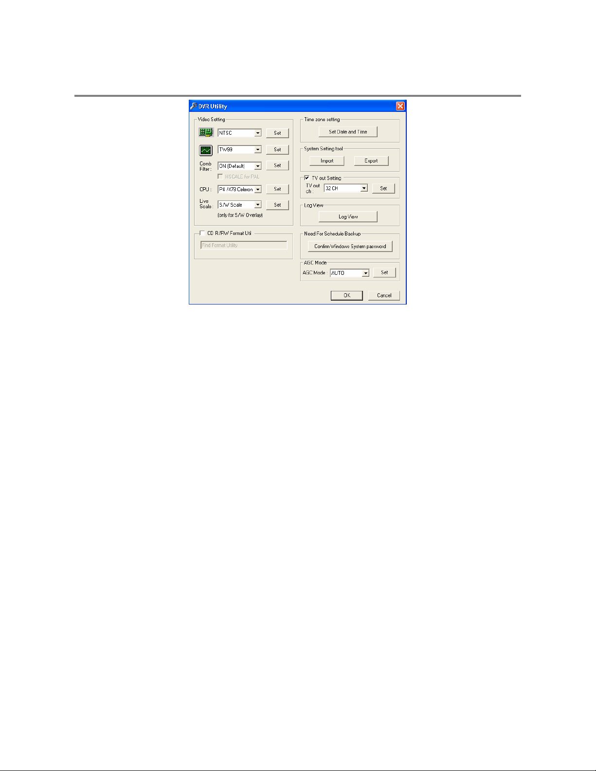
USING THE DVR UTILITY
Exporting DVR Settings
Exporting DVR settings can help configure multiple DVRs quick ly or reconfigure a unit that has failed. Some things must be k ept in
mind when using this feature.
You cannot use this function on:
1. Exit to Windows by clicking the Exit Button on the Main Display Sc reen and s elec ting Res tart in Wind ows Mode. (Se e the Disp lay
2. Click Start > Programs > Surveillix > VFormat
3. Click the Export Button in the System Settings tool section.
4. Select a location to save the settings file and click Save. The DVR Utility will export the DVR settings and automatically close.
5. Click the OK Button to close the VFormat Utility.
• DVRs that are different models.
• When upgrading from certain software versions. You cannot use this feature when upgrading from
v1.x to v2.x
Screen section later in this chapter)
Importing DVR Settings
1. Exit to Windows by clicking the Exit Button on the Main Display Sc reen and s elec ting Res tart in Wind ows Mode. (Se e the Disp lay
Screen section later in this chapter)
2. Click Start > Programs > Surveillix > VFormat
3. Click the Import Button in the System Settings Tool section.
4. Select the location of the settings file to import and click Open.
5. Click Yes to import the data file.
6. Click the OK Button to close the VFormat Utility.
Page 14
4
Changing Video Format
1. Exit to Windows by clicking the Exit Button on the Main Display Sc reen and s elec ting Res tart in Wind ows Mode. (Se e the Disp lay
Screen section later in this chapter).
2. Click Start > Programs > Surveillix > VFormat.
3. Select the appropriate video setting from the list in the Video Setting Section – NTSC or PAL.
4. Click Set
5. Click the OK Button to close the VFormat Utility.
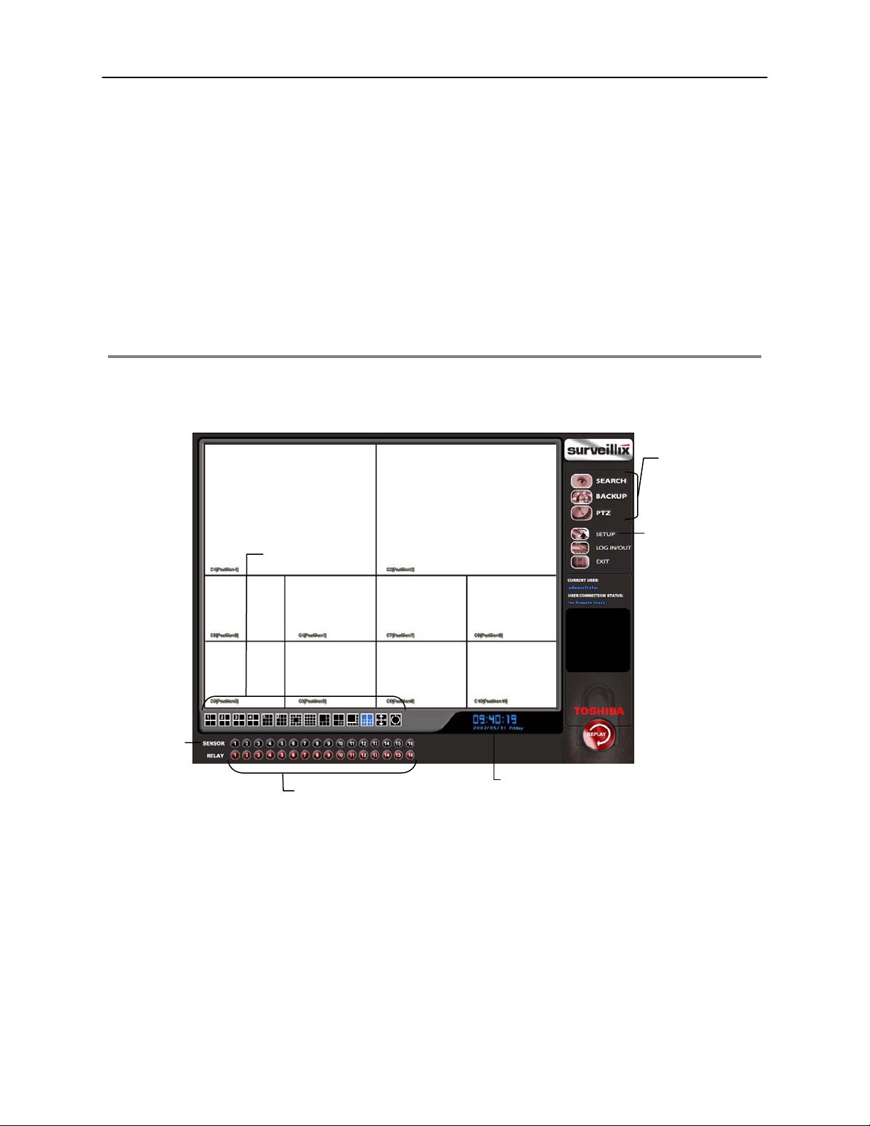
DISPLAY SCREEN
Each time the DVR is started, the program defaults to the Display s creen. The following diagram outlines the buttons and featu res
used on the Display screen. You should beco me familiar with these options as this is th e screen that will be displayed the maj ority of
the time.
Opens:
• Search Display
• Backup Center
• PTZ Controller
Opens Setup Display
Screen Division Buttons
Sensor Status
Relay Outputs
Current Date / Time
Page 15
5
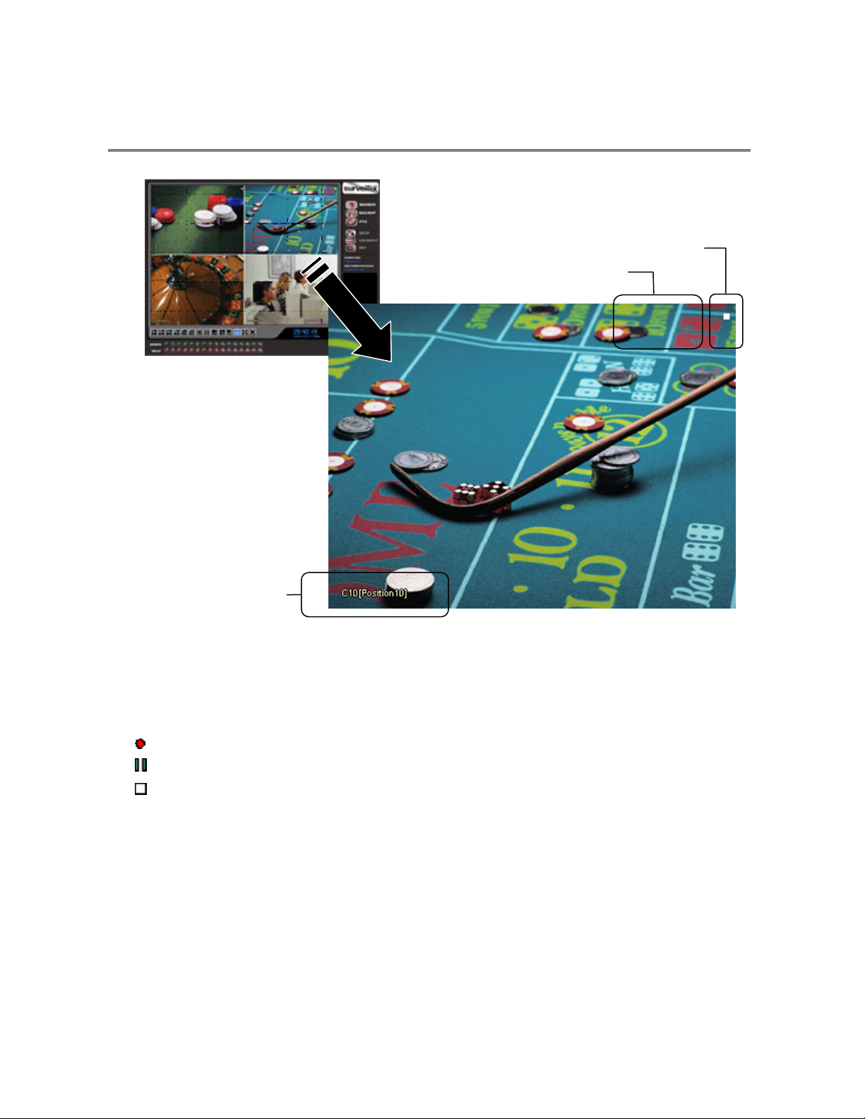
CAMERA VIEW
The Camera status for each camera is displayed next to the Camera number (or name) on the Video Display Area. The following are
Recording Status
Special Recording Type
INSTANT
Camera No. and Name
Recording Status Indicator
The camera status for each c amera is displayed in the upper right corner on the Vid eo Display Area. The following are the di fferent
states for each camera:
Recording Displayed when the camera is currently being recorded to the DVR unit.
Motion Detection Displayed when a camera (set up for motion detection) detects motion.
Display Displayed when the camera is currently not being recorded to the DVR unit.
Special Recording
There are two types of DVR Special Recording. Text is displayed on the camera indicating what type of Special Recording is
activated.
SENSOR Sensor is displayed when a sensor, associated with a given camera, is activated.
INSTANT Instant Recording is a manua l activa tion of th e rec ording f or the selec ted camer a. Regar dles s of th e recor ding metho d,
Instant Recording will start the camera recording and also flag the video for future searches using the Index Search
feature. INSTANT is displayed when a user ac tivates th e instant recordin g optio n. Double R ight-Click the video display
to activate and deactivate the Instant Recording option.
Page 16

6
SCREEN DIVISION BUTTONS
The Screen Division Buttons allow you to view cameras in groups such as two by two, three by three and four by four. The button
options are shown below.
1st Four Cameras View – Displays cameras 1-4 i n the Video Display Area. To return to a differ ent Multi-Camera
View, select a different Screen Division option from the Screen Division Menu.
2nd Four Cameras View – Displays cameras 5-8 in the V ideo Display Area. To return to a different Multi -Camera
View, select a different Screen Division option from the Screen Division Menu.
3rd Four Cameras View – Displays cameras 9-12 in the Video Display Area. To r eturn to a different Multi-Camera
View, select a different Screen Division option from the Screen Division Menu.
4th Four Cameras View – Displays cameras 13- 16 in the Video Display Area. To return to a differ ent Multi-Camera
View, select a different Screen Division option from the Screen Division Menu.
1st Nine Cameras View – Displays cameras 1-9 in the Video Display Area. To return t o a different Multi-Camera
View, select a different Screen Division option from the Screen Division Menu.
2nd Nine Camera View – Displays cameras 8-16 in the Video Display Area. To return to a different Mult i-Camera
View, select a different Screen Division option from the Screen Division Menu.
Multi-Camera View – Displays a group of cameras within the Video Display Area.
All Camera View – Displays all 16 cameras within the Video Di splay Area.
Multi-Camera View – Displays a group of cameras within the Video Display Area.
Multi-Camera View – Displays a group of cameras within the Video Display Area.
Full Screen – The Full Screen Option allows y ou to view the Video Display Area using the entire viewable area on
the monitor. When this is selected, n o menu options are visible . You can activate the Full Sc reen Option by clicking
on the Full Screen Button within the Screen Division Menu. You c an deactivate Ful l Screen mode by right clic king on
the screen.
Auto Sequence – Sequences through the Screen Divisions sets . For example, selecting the 1A and then the L oop
Button will sequence through 1A, 2A, 3A, 4A and then repe at. This optio n is not available f or the 7, 10 and 13 screen
divisions.
Page 17

7 8 9
Page 18

Page 19

SETUP OPTIONS
This chapter includes the following information:
• Setup Overview
• Channels
• Color
• Schedule
• Speed
• Motion Detect
• Password
• Pan/Tilt
• Audio
Page 20
10
SETUP OVERVIEW
The Set up opt ions allow y ou to opti mize your DVR unit by adjustin g things lik e camera na mes, reboot s chedules, rec ording sc hedules
and more. It is extremely important that you setup your DVR correctly for several reasons.
• Recording Schedules – By optimizing the recording s chedule you can increase th e amount of pertinent recorded v ideo that is
saved on the DVR and keep it longer. You can optimiz e the type of recording done by adding motion detection to this as well,
again increasing the amount of useful video.
• DVR Access – By setting up the access passwords you can tigh tly control the types of access an individual may have. Thi s
ensures the security and integrity of the DVR unit.
• Camera Naming – By naming each camera you c an easily ident ify the locatio n and any other perti nent informati on that may be
helpful simply by viewing it on the Video Display Area.
• Adjusting Camera Color – By adjusting each camera’s color settings you can optimize the clarity and detail that is recorded.
SETUP SCREEN OVERVIEW
Setup Options
Page 21
11
A
A
y
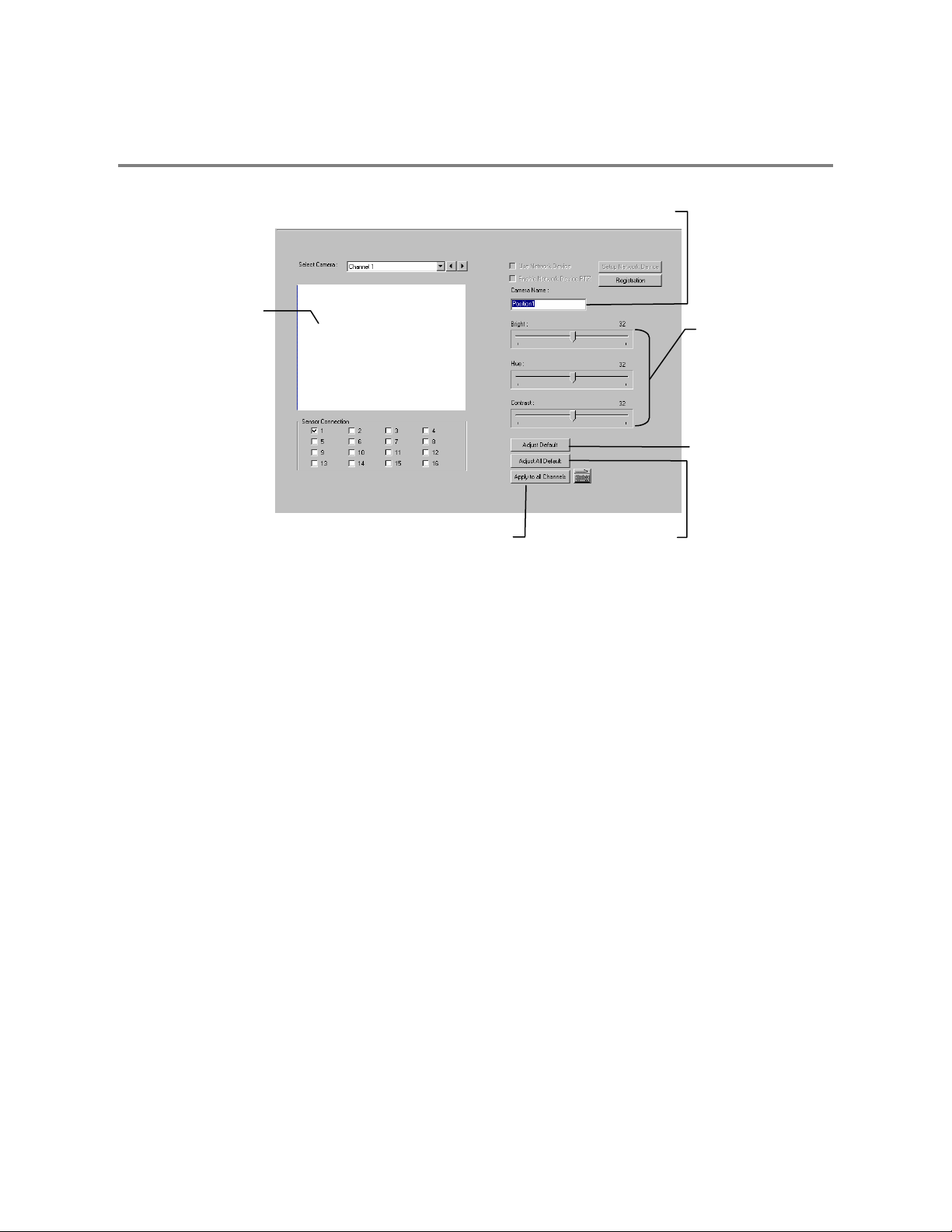
CAMERA SETUP
Selected Camera
Displa
Define Camera Name
Adjust
• Brightness
• Hue
• Contrast
Apply System Defaults
to Selected Camera
pply Current Settings
to all Cameras
pply System Defaults
to All Cameras
Setup New Camera
1. Attach camera to the rear of the DVR chassis.
2. Click the Setup Button on the Main Display Screen.
3. Click the Camera Setup Button to open the Camera Setup Display.
4. Select the channel that corresponds with the new camera from the Select Camera Drop Down Menu.
5. Enter a name for the camera in the Camera Name Field.
6. Adjust the Brightness, Hue and Contrast if necessary.
7. Select the appropriate sensors to associate with the camera.
8. Click the Apply Button when finished.
Page 22
12
HVR Registration (DVR/EVR Upgrade Option)
Use the following instructions to register the netw ork recording functionality of an HVR or upgraded DVR/EVR. Contac t your sales
representative to purchase the HVR upgrade for a DVR or EVR.
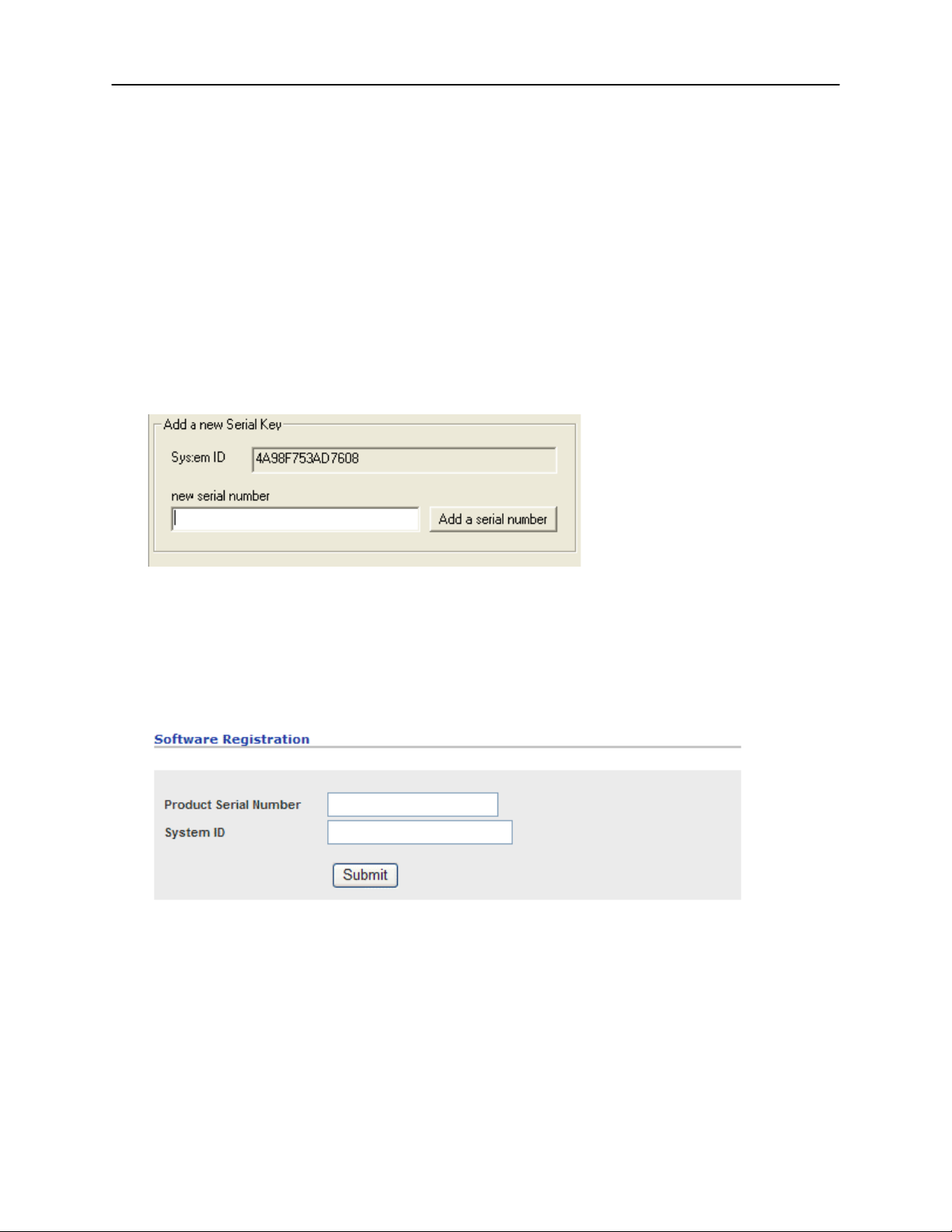
Have the following information available before registering the HVR upgrade.
HVR Software Serial Number: The product Serial Number is the unique number that Toshiba provided with the software purchase.
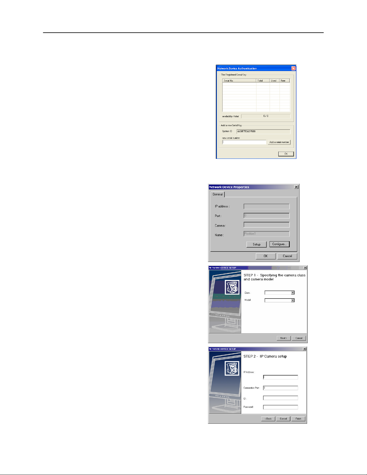
System ID: The System ID is a number generated by the Surveillix unit. This is a unique code g enerated using the MAC address of
the computer running the software. The following steps illustrate how to locate the System ID.
1. Enter Setup
2. Click Camera Setup
3. Click the Registration Button
4. In the Network Device Authentication, the System ID can be located under the “Add a new Serial Key” section (shown below)
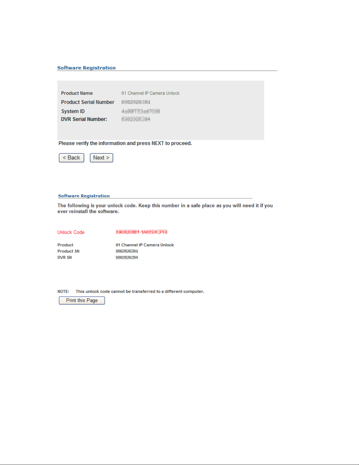
Obtaining the Unlock Code
1. Open an Internet browser and go to: http://register.surveillixdvrsupport.com
2. Enter the Product Serial Number that was provided by Toshiba
3. Enter the System ID that was generated by the unit
4. Click Submit
5. Verify the information
6. Click Next if the information provided is correct
Page 23
13
7. Once validated, the user will be provided with the Unlock Code
8. Print the page and save for later reference
Page 24
14
Unlocking a New Network Camera
1. Start the Surveillix DVR
2. Enter Setup
3. Enter Camera Setup
4. Click the Registration Button
5. Enter the Unlock Code generated by the Toshiba
Registration Site into the “new serial number” field
6. Click Add a serial number
7. Once the new serial number has been added to the list,
click OK
Connecting a Network Camera
1. Open Camera Setup. Setup > Camera Setup
2. Select the camera channel to add a Network Device to.
3. Check the Use Network Device Box.
4. If the Network Device supports PTZ check the Enable Network
Device PTZ Box.
5. Click Setup Network Device and the Network Device Properties
Window will appear.
6. Click Setup to add a Network Device.
7. Select the Manufacturer (Class) and Model of camera being added
then click Next.
8. Enter the IP Address, Port, ID, and Password of the Ne twork Dev ic e
and click Finish.
9. Click OK when returned to the main Network Device Propertied
Window and click OK to exit the main setup window.
10. The Network Device has been added.
Page 25
15
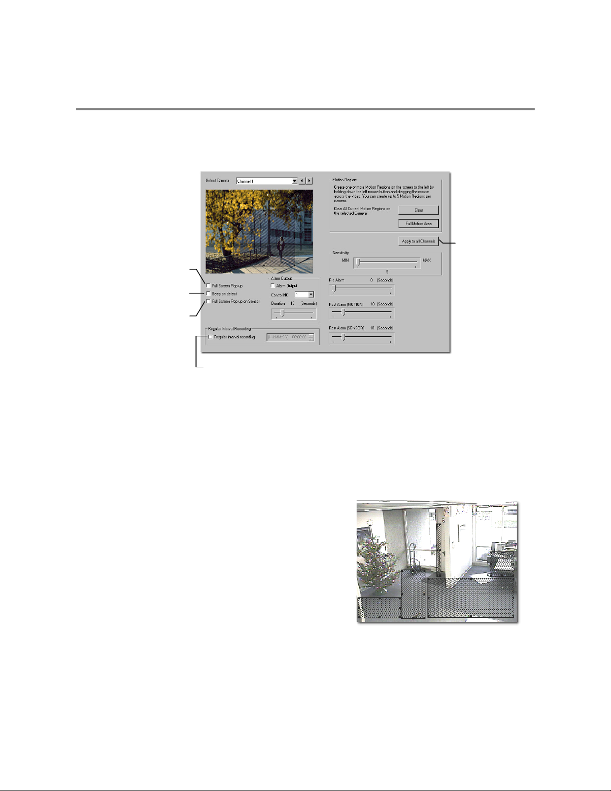
MOTION SETUP
The DVR unit allows the user to adjust several different Motion Settings and create motion detection regions.
Display full screen video
pop up on motion event
Beep on motion event
Display full screen video
pop up on sensor event
Apply current settings
to all channels
Schedule recording at a
regular specified interval
Create a Motion Region
1. Select a camera channel
2. Place the mouse pointer at the upper l eft hand cor ner of th e area t o
designate, click and hold down the left mouse button, drag the
mouse. Let go of the button when the box is the size desired.
3. Create up to five Motion Regions per camera. Resize and move
them by dragging the sides and corners of the box.
4. Adjust the sensitivity of the motion area using the sensitivity slider.
5. Define the recording time for a motion event
Pre Alarm – 0 > 60 Seconds [The number of seconds the DVR
records before motion is detected]
Post Alarm (MOTION) – 0 > 60 Seconds [The number of seconds
the DVR records after motion is detected]
Page 26

16
Activating an Alarm on a Motion Event
1. In the Motion Setup window, select a camera to edit from the drop down menu
2. Create a motion area.
3. Select the Alarm Output box.
4. Select a Control Output to activate for the selected camera.
5. Select the duration to activate the Alarm when a motion event occurs.
Page 27
17
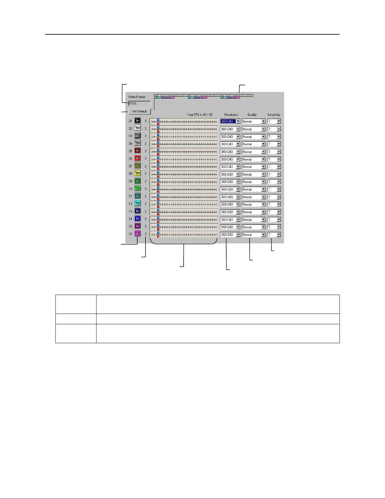
FRAME SETUP OVERVIEW
The Frame S etup Menu allows configuration o f the PPS, resoluti on, quality , and sensitiv ity of camera c hannels. When conf iguring the
PPS sliders the BLUE slider represents the PPS the DVR will record during intensive recording a nd have available for transmitting to
remotely connected systems. The RED slider represents the PPS that will be recorded by the DVR under normal recording conditions.
The total PPS of all blue sliders may not exceed the recording PPS of the DVR unit. The PPS of a red slider may not exceed that of
the blue slider for the same channel. The dual slid ers allow configur ation of th e DVR to record at a lower PPS while stil l being able to
transmit at a higher PPS to remote connections.
Ex. If a camera channel is set to 25 PPS (blue) and 7 PPS (red), the DVR will record at 7 PPS and users viewing live video remotely
can receive up to 25 PPS.
NOTE: The 4 Channel XVR only allows the user to select one frame rate for both recording and remote viewing.
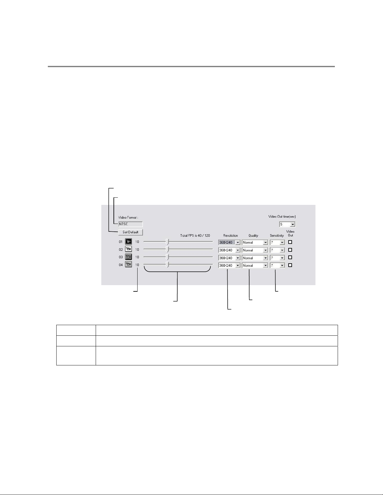
Frame Setup (4 CH x120 model)
Reset Default Settings
Video Format – NTSC/PAL
No. of Recording Frames Selected
Frame Select
Recording Resolution
Frame Select Sets the PPS recorded by the XVR and available for viewing on a remote client PC
Video Quality Lower quality video has a smaller file size but appears more pixilated
Sensitivity Sets the Keyframe refresh rate. Adjusting this setting can have negative effects on video quality
NOTE: Do not change from default setting unless instructed by a system administrator.
Video Quality
Sensitivity
Page 28
18
r
Frame Setup (x120R, x240, x480 models)
Reset Default Settings
Select Camera Colo
(used in Frame Status Box)
No. of Recording Frames Selected
Video Format – NTSC/PAL
Frame Select
Frame Status Box
Sensitivity
Video Quality
Recording Resolution
Frame Select Blue Slider: Sets the PPS recorded during intensive recording and available for viewing on a remote client PC.
Red Slider: Sets the PPS recorded by the DVR during normal recording.
Video Quality Lower quality video has a smaller file size but appears more pixilated.
Sensitivity Sets the Keyframe refresh rate. Adjusting this setting can have negative effects on video quality.
NOTE: Do not change from default setting unless instructed by a system administrator.
Page 29
19
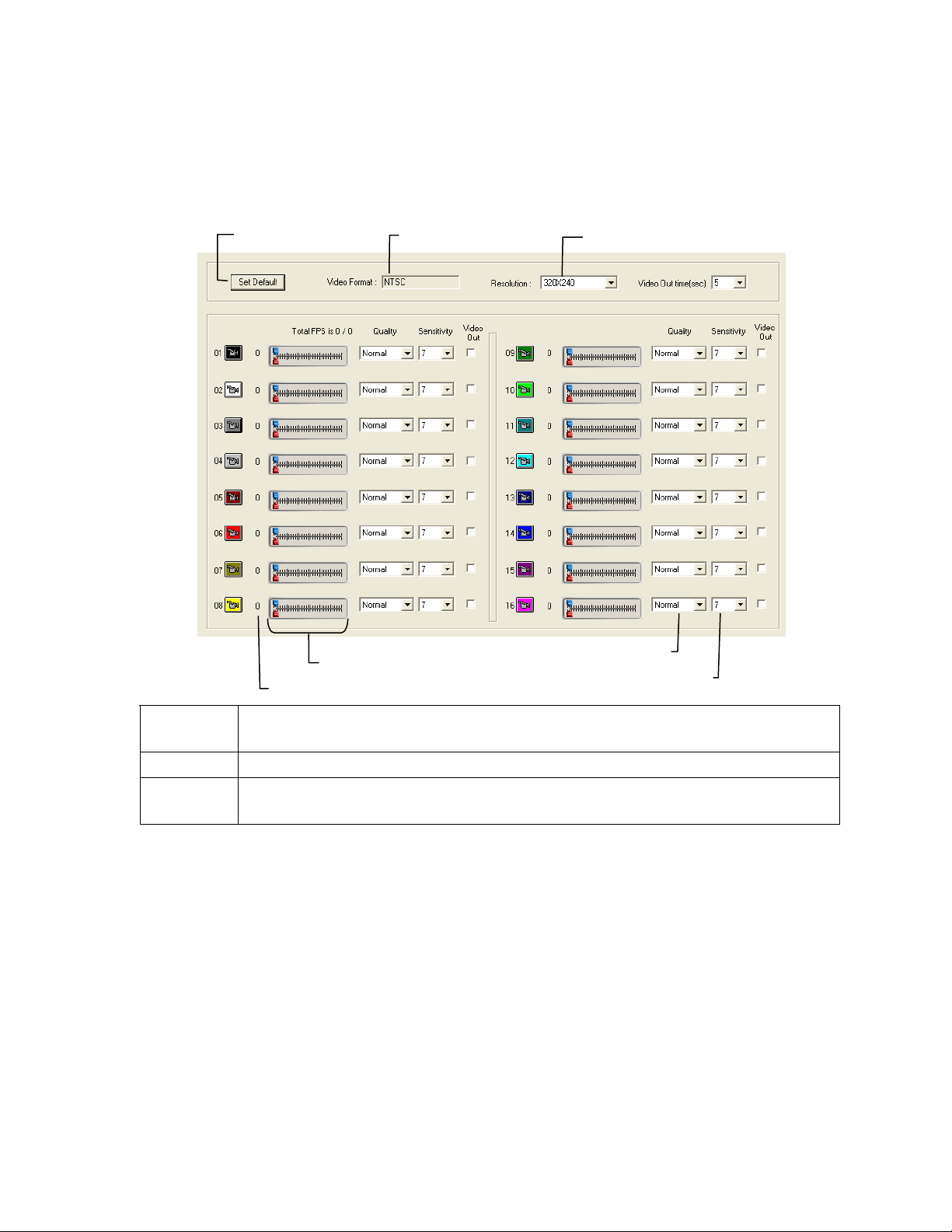
Frame Setup (x60, x120 models)
Reset Default Settings
Frame Select
No. of Recording Frames Selected
Video Format – NTSC/PAL
Global Recording Resolution
Video Quality
Sensitivity
Frame Select Blue Slider: Sets the PPS recorded during intensive recording and available for viewing on a remote client PC.
Red Slider: Sets the PPS recorded by the DVR during normal recording.
Video Quality Lower quality video has a smaller file size but appears more pixilated.
Sensitivity Sets the Keyframe refresh rate. Adjusting this setting can have negative effects on video quality.
NOTE: Do not change from default setting unless instructed by a system administrator.
Enable Video Out to Spot Monitor
1. Click the Setup Button on the Main Display.
2. Click the Frame Setup Button.
3. Select the Video Out Box to enable the appropriate channels.
4. Define the Video Out Time (seconds to display each channel on spot monitor).
5. Click Apply.
Page 30

20
Maximum PPS Table
PPS Breakdown for Each Resolution
Resolution CCTV x480 model x240 model
360x240 1CIF 480 PPS 240 PPS
720x240 * 2CIF 240 PPS 120 PPS
720x480 ** 4CIF 120 PPS 60 PPS
* Frames recorded in 720x240 are twice the size of the standard 360x240. When recording at
720x240, each frame assigned to the channel will use 2 of the total frames available.
** Frames recorded in 720x480 are four times the size of the stand ard 360x240. When recording at
720x480, each frame assigned to the channel will use 4 of the total frames available.
Resolution CCTV x120 model x60 model
320x240 1CIF 120 PPS 60 PPS
640x240 2CIF 120 PPS 60 PPS
640x480 4CIF 60 PPS 30 PPS
32 Channel Frame Allocation
32 Channel models utilize two capture cards. When configuring c ameras and allocating frames, the
total frame rate for the DVR is split between each capture card. Please referenc e the chart below for
available frames for each grouping of channels.
Resolution Channels x240 model x480 model
360x240
720x240
720x480
1 to 16 120 frames 240 frames
17 to 32 120 frames 240 frames
1 to 16 60 frames 120 frames
17 to 32 60 frames 120 frames
1 to 16 30 frames 60 frames
17 to 32 30 frames 60 frames
Page 31

21
/
SCHEDULE SETUP
Recording Schedule
The R ecording Sched ule Window al lows the user to c reate differ ent recording s chedules bas ed on the day , time, and ty pe of recording
desired. In addition, this window contains the System Res tart options that allow the user to perform basic system maintenance by
automatically scheduling the DVR to restart periodically.
Recording Schedule Window
Single Day Selection
Multi Day Selection
Open Restart
Setup Window
Create Special Day
Recording Schedules
Recording Mode Options
Emergency IP Setup
Page 32

22
/
t
Sensor Schedule
The sensors will supersede a ll other types of recording modes (Motion, Continuous, No Recording). Regardless of the recording
schedule of a particular camera, if a sensor event oc curs the associated cameras will begin recording as a Sensor Event. Sensor
Recordings will be flagged and searchable using the Index Search Mode. Cameras are a ssociated to sensors in the Camer a Setup
Menu.
Sensor Schedule Window
Single Day Selection
Multi Day Selection
Open Restar
Setup Window
Create Special Day
Sensor Schedules
Alarm Options
Emergency IP Setup
Page 33

23
Create a Recording Schedule
1. Select a day to begin creating the schedule for -or- Select the Day Selection Mode Button, enabling
Multi Day Selection, to create the same schedule for multiple days.
2. Highlight the Time-Blocks within the Recording Schedule Window for the camera(s) selected to schedule. Once the desired
Time-Blocks are highlighted, click a Recording Mode Button. The Time-Blocks should now appear Blue for Motion, Yellow for
Continuous and White for No Recording
NOTE: Leave cameras recording with Sensor Detection set to No Recording for the specified time block(s).
Create a Sensor Schedule
1. Select the Schedule Menu option and select the Sens or Radio Button. Select a single day or click the Day Selection Mo de
Button to include multiple days in the schedule.
2. Highlight the Time-Blocks within the Recording Schedule Window for the sensor(s) to enable and schedule. Once the time
blocks are highlighted click the Enable Button. The time block will now appear red.
Scheduling Alarm Events
There are three types of Alarm Events:
ALARM EVENT: This option logs the Alarm Events on the local server.
CENTRAL STATION: This option sends the Alarm Events to Central Station software.
EMERGENCY AGENT: This option sends the Alarm Event to the Emergency Agent software.
Motion can be designated as an Al arm event. Often motion does not need to be trea ted as an Alarm event. Ex: During work hour s
motion that occurs is expected and should not be treated as an Alarm. However, after business hours are over, any motion that
occurs should be treated as an Alarm.
1. Select the Schedule Menu – Select either Recording or Sensor
2. Highlight time blocks in the schedule that have been set to Mot ion (or Sen sor) and c lick the desired Ev ent but tons (Alarm Event ,
Central Station, Emergency Agent). A corresponding letter will display in the selected time blocks
Emergency Agent Schedule
Video recording triggered by motion or sensor events can be sent to the Emergency Agent software.
1. Enable the Emergency Agent Event (see Scheduling Alarm Events above)
2. Enter the IP Address of a PC running the Emergency Agent software in the IP Address
3. Select the box next to the IP Address to enable it. Only one IP Address is supported at a time.
4. Enter the recording duration (in seconds) in the Emergency Time field.
5. See the Emergency Agent chapter for detailed information on setting up the Emergency Agent software.
Page 34

24
r
Special Day Schedule
The user can c reate days that have a unique recording schedule. If necess ary create these on days that are ‘not typical’ such as
Holidays, Special Events, etc.
Special Day Mode / Normal Day Mode
Date Ba
Configured Special Days List
Creating/Editing a ‘Special Day’ Schedule
1. Click the Normal Day Mode Button to enable the Special Day Mode.
2. Select a day by typing the date or clicking the arrow to the right of the Date Bar.
3. Highlight the time-blocks within the Recording Schedule Window for the camera(s) selected to schedule. Once the desired TimeBlocks are highlighted, click a Recording Mode Button.
4. When finished creating the schedule click the Save Special Day Button. The s pecial day should now appear as a date in the
Special Day Schedule.
Deleting a ‘Special Day’ Schedule
1. Select a Special Day from the Special Day Schedules
2. Click the Delete Special Day Button.
Page 35

25
System Restart Setup
System Restart Setup allows the user to define a schedule wherein the DVR automatically restarts according to specified parameters.
Create System Restart Schedule
1. Open the Schedule Setup Display
2. Click the System Restart Button
3. Select the day(s) of the week to schedule an automatic system restart and select the box to enable shut down
NOTE: This step alone does not trigger the DVR to restart, only to shut down.
4. Specify the time of day to schedule the system restart
5. Select the Restart Radio Button
NOTE: If the Off Radio Button is selected the DVR will shut down at the specified time but not restart.
Page 36

26
/
)
ALARM SETUP
The Sensor and Output Window allows you to enable, disable and configure Sensors and Control Outputs.
Create & Name Sensor Presets
Open On-Screen Keyboard
Normally Open (NO)
Normally Closed (NC
Configure Hybrid (IP) Sensors*
Delay Triggering Relay Output
Assign Relay(s)
comma delineated
*Requires the HVR Software Upgrade
Configure Sensor Response
1. Click the Setup Button on the Main Display Screen.
2. Click the Alarm Setup Button to open the Sensor and Output Display.
3. Click to select NO or NC for the desired sensor.
4. Enter the Delay Time to define the number of seconds after the sensor is tripped until the relay is activated.
5. Enter the relay(s) to associate wit h the sensor. Two or more relays can be associated with a single sensor – separ ate with
commas.
6. Click Apply.
Page 37

27
Activate PTZ Preset on Sensor
1. Create PTZ Preset Position. See instructions in the PTZ Setup Chapter.
2. Click the Setup Button on the Main Display Screen.
3. Click the Alarm Setup Button to open the Sensor and
Output Display.
4. Click the Sensor Preset Button.
5. Select the desired camera from the Channel Drop Down
Menu.
6. Select the appropriate sensor from the drop down menu.
7. Select the preconfigured PTZ Preset from the drop down
menu.
8. Click the Set Button. A list of configured Sensor Pr esets
will display in the box below.
9. Repeat for additional sensors.
10. Click the OK Button to close the Sensor Preset Window.
Page 38

28
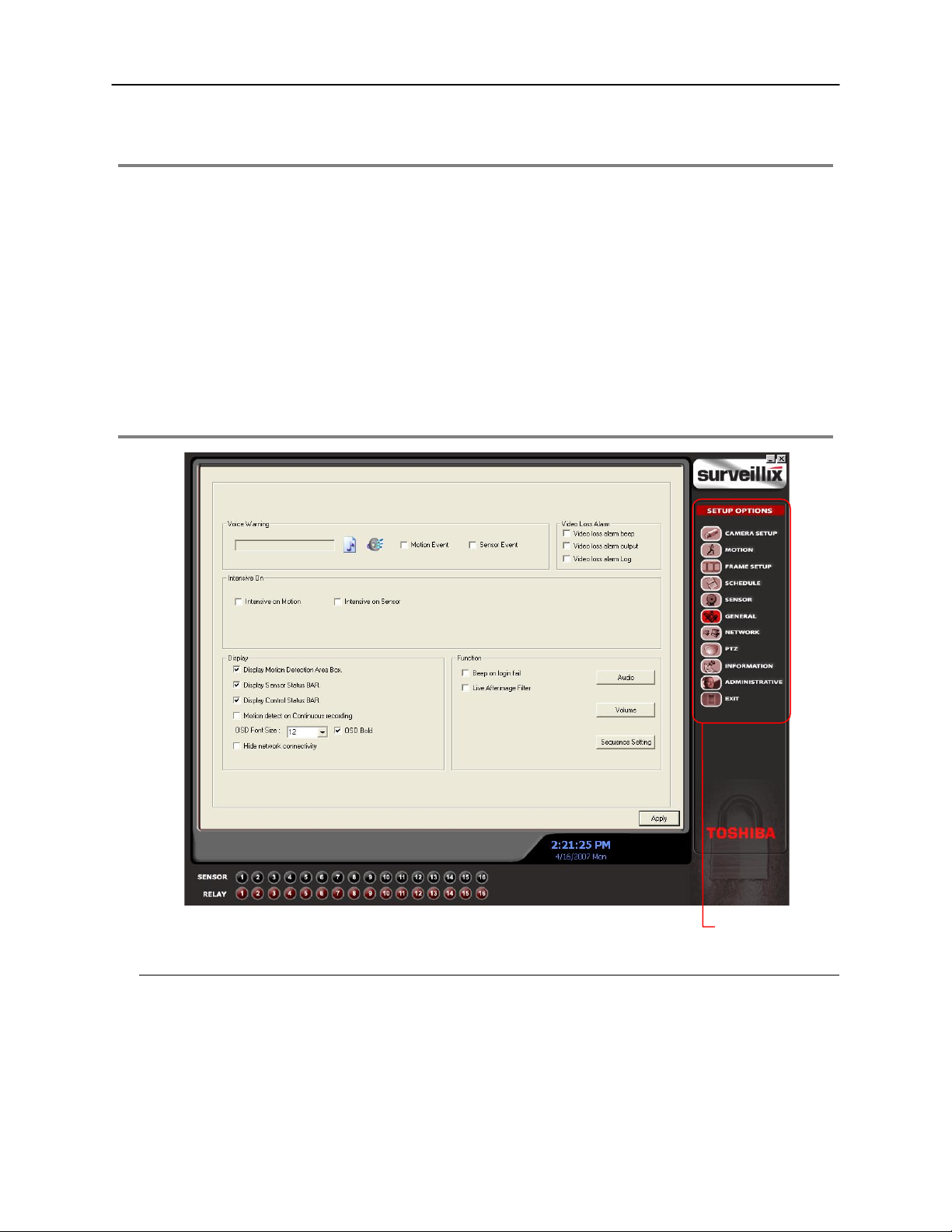
GENERAL SETUP
Enable Intensive
Recording
Enable Audio Recording
Adjust / Mute Volume
Beep on Login Fail Enables the DVR to beep continuously in response to a failed login attempt. Only an aut horized login will
stop the beeping.
Sequence Setting Allows the video out picture to automatically cycle through channels at a set speed. Ex: .Cycle through
channels 1-6 at 4 second intervals.
Voice Warning
The DVR unit allows users to p lay a sound file when eith er a Motion event or Sensor event occur. This file can be a custom cre ated
sound file that is unique to the application. The selected WAV file is played through speakers attached to the DVR unit.
Open Sound File
1. Click the Open Sound File icon to browse for a WAV file. The selected file will display in the field on the left
2. Click the Test icon to verify the audio file
3. Select Motion Event and/or Sensor Event to trigger the audio file
Test
Page 39

29
Intensive Recording Overview
The Inte nsive Recording Option allows you to increase the Pictures Per Sec ond and the resolution of any camera recording using
sensor activation. When the intensive recording is activated, the resolution of the remaining cameras is immediately reduced to
360x240 and the Pictures Per Second to a user-speci fied level. This guarantees that the Pictures Per Second and Resol ution will be
set correctly and not exceed the DVR limitation.
How to Use Intensive Recording
The Intens ive Recording option is set up as ‘All or Nothing’. This means that o nce enabled (associated with sensors); all cameras
associated with sensors will activate the Intensive Recording.
To activate the Intensive Recording option, follow these steps.
1. Inside Camera Setup, select the camera to use and enable the sensor to associate with it.
2. Click on General Setup. Enable the Intensive on Sensor and/or Intensive on Motion option.
3. Click on Schedule Setup. Select the Sensor Radio Button.
4. Enable the sensor by creating a schedule for it
5. Click the Apply Button and exit out of setup.
Audio
The Surveillix DVR is capable of recording up to 4 channels of audio.
AUDIO FEATURES:
• 8000 Hz playback in Live Mode
• Up to 48000 Hz playback in search mode
• Mono Sampling
DATA SIZE (Per channel)
• 1 Second: 1625 bytes
• 1 Minute: 97,500 bytes
• 10 Minute: 975,000 bytes
• 1 Hour: 5,850,000 bytes
• 1 Day: 140,400,000 bytes (Approx 140MB)
Click the Audio Capture Channel Boxes to enable recording and adjus t the
Gain to the desired level.
Page 40

30
TV-Out Setup
The DVR unit feat ures an opti onal TV -Out functional ity that a llows users to output v ideo fr om any nu mber of cameras, in sequ ence, t o
a television or monitor display.
1. Select the TV Out Port to use
NOTE: Each Port must be configured individu ally, i.e. one after
the other.
2. Select the Use Box to enable TV-Out functionality for th e
selected port.
3. Select each camera to display through the TV-Out port.
4. Select and Event Popup Box if desired
5. Define the Event Holding Time (the number of seco nds the
camera displays after an event) for selected event types
6. Define the Auto Switching Time (the number of seconds
between switching of camera) for the selecte d TV Ou t Port
Volume
The volume control allows fine tuning of the volume settings on the DVR.
Volume Options:
• Slider Controls – Used to adjust the literal volume for the
respective devices listed.
• Mute Checkbox – Check the mute box to mute volume on
any of the device columns or check the Mute All checkbox to
mute all volume on the DVR.
Page 41

31
Auto Sequencing Setting
Auto Sequencing is used either in the main screen when Auto Sequenc ing has been enabled or when a Spot-Monitor Out signal is
used to display video on a spot m onitor. Auto S equencing conv eniently displ ays video c hannels and at specified in tervals, seque nces
through each selected channel.
Screen Division Options
Enable Sequencing
Enable All Cameras
Select interval between
switching cameras
Channel Selection Click each channel to include in Auto Sequencing.
Custom Mode Enable to create non-standard screen divisions
Skip 0 FPS Channel Sequence skips cameras with no video signal.
Create Custom Auto Sequence
1. Open General Setup and click the Sequence Setting Button
2. Click individual cameras in the left pane or click the Select All Button to include all cameras in the sequence
3. Select an interval time (in seconds) to display each screen in the sequence
4. Select Screen Division options for appropriate cameras
5. Click the OK Button
Page 42

32
o Remote Clie
NETWORK SETUP
Network Setup allows the user to adjust settings such as P orts, setup emergency PPP information for use with the Emergency Agent
and enable Remote Access.
Use with Remote
Connections
Enable RS-232
Keyboards (PTZ)
Settings for Video Sent
t
Use with
Emergency Agent
Between DVR and
Remote Client
nt
Transport Rate A bandwidth throttle based on percentage of free network.
Web Viewer (iDVR) Enables/Disables access to the DVR using the Web Viewer interface.
Page 43

33
r
PTZ SETUP
The PTZ Setu p Window allows enabling of PTZ cameras, creation of Presets, creation of Tours, and ad justment of camera speed
settings. Many options listed here are fea tures only availa ble on s elected camer as. Refer t o the PTZ chapter in this manual for further
information on setting up PTZ cameras and setting PTZ options.
INFORMATION
The Information Display allows users to define the site code nec essary for connecting to remote softwar e, save comments relati ve to
the DVR and store tech support and contact number information.
Total HDD /Available HDD Space
Enter comments
Site Code A user-specified unique identification name used by other DVR software to identify the DVR. (Remote,
Emergency Agent, SCS, Digital Signature Verifier)
Current Serve
Software Version
User-Defined
Contact Numbers
Page 44

34
ADMINISTRATIVE SETUP
Safely Remove Connected Device
Change Data Storage Location
Select Date
Log Data Display
Export Log Data
(1 to 7 days)
Page 45

35
Storage Check
The Storage Check allows users to configure E-mail alarms, assign users to E-mail alarms and configure storage checks on the
Surveillix DVR.
General Configure E-mail alarms for the Surveillix DVR.
Users Configures which users will receive E-mails on alarm events
Storage Check Configures when storage checks will be performed and their frequency.
Recording Data Check Configures when recording checks will be performed and their frequency.
Alarm Event Configures when general alarms will be sent.
Disk Management
The Disk Manage ment window is a native Windows fu nction. This window display s the partition sc heme and health status of th e Hard
Disk Drives in the DVR. This window is often used to troubleshoot a D VR, or verify the amount of Hard Drive storage installed. For
more information about Disk Management, consult a Windows XP manual.
Page 46

36
f
User Management
The User Management Console allows the administrator to create, edit, and delete user ac counts . Each us er account c an be as signed
different privileges to limit the usage of the DVR system. Users can be given administrator privileges by enabling all rights, however
only the true administrator account can log into the User Management Console.
Enable Auto Log Of
Log Off User after x Minute(s) of Inactivity*
NOTE: The Delete User Button immediately deletes the user – use cautiously
Add a New User
1. Open the Administrative Setup Display
2. Click the User Management Button
3. Click Add User to open the User Management Window.
4. Enter a user name and password.
5. Enable appropri at e Permiss ions .
6. Select cameras to hide from the user.
7. Assign a User Rank
8. Click the OK Button to save changes and close the window
*Auto Log Off affects all users
Page 47

37
User Rank
The User Ranking structure allows the option to assign a privilege system (1-10 where one has the most rights) to users of the DVR
Software. For example: Since only one user is allowed to use the PTZ controls at any one time, an adminis trator with a higher rank
can kick another user out and take control of the PTZ.
The User Rank option affects:
SETUP ACCESS – Only one user can access Setup at any one time. A user with a h igher rank will kick another user out and then
open Setup.
PTZ CONTROL - The DVR Software can only have 1 user using the PTZ c ontro ls at a ny g iv en ti me. A us er with a higher rank will kick
another user out and then open the PTZ controls.
1. Enter Setup.
2. Click the Administrative Button.
3. Click the User Management Button.
4. Enter the Administrator password and click OK.
5. Select a user from the Select User field and click the Update User Button.
6. Set the user’s rank using the User Rank drop down menu and press the OK Button to save changes.
Changing the Administrator Password
1. Inside Administrative Setup, click the User Management Button. When the prompt appears, click the Change Password Button.
2. Enter the new password in the prompt that appears and click OK.
Default Administrator Password
The default administrator login is:
User: Administrator
Password: <none>
Log Management
The Log Management window provides the user the options to overwrite log files or schedule log deletion.
Setup Log Management Options
1. From the Administrative Setup Display click the Log Management Button
2. Select the box to enable the Log File Overwrite Option
Set Log Overwrite
a. Select Overwrite and define the size of the log file cache
Set Log Cache Size
a. Select Do Not Overwrite and define the number of days to maintain log files.
Manually Delete Log Files
a. Select the type(s) of log file to delete. System Log, Event Log, Alarm Log
b. Click the Delete All Button
3. Click the OK Button to save the settings and close the window
Page 48

38
NOTES:
Page 49

39
Page 50

40
SEARCH
This chapter includes the following information:
• Setup Overview
• Channels
• Color
• Schedule
• Speed
• Motion Detect
• Password
• Pan/Tilt
• Quit to Explorer
Page 51

41
SEARCH OVERVIEW
The DVR unit has several opti ons that allow the user to easily search, and find, a particular section of video. From Moti on/Sensor
indexing to calendar views highlighti ng days with recorded video; the DVR unit is equipp ed to help the user quickly find a specific
video or event.
The following chapter describes in detail how to use the DVR search features.
Screen Division Buttons
Calendar Button
Hour/Minute Control Bar
Playback Date/Time
Current Date/Time
NOTE: Audio Channel Buttons are only viewable when one camera is selected.
Play Controls
Rewind
Back Frame
Stop
Play
Forward Frame
Back Frame Moves video back one frame.
Rewind Rewinds video.
Stop Stops video playback
Play Plays video.
Forward Frame Moves video forward one frame.
Play Controls
Audio Channels
Camera Select Buttons
Page 52

42
Adjust the Brightness of an Image
1. Select an image to adjust by double-clicking on the desired image. Multiple images cannot be adjusted at one time.
2. Move the Brightness slide bar to the right or left to adjust the brightness.
3. Reset the Brightness by moving the slider back to the center of the bar.
Zooming In On an Image
1. Select an image to adjust by double-clicking on the desired image. Multiple images cannot be adjusted at one time.
2. Move the Zoom slide bar to the right or left to zoom in or out of an image.
3. Reset the Zoom by moving the slider back to its original position on the bar.
Zooming In On a Portion of an Image
1. Using the mouse pointer, point to the area of interest on the image and click the right mouse button.
2. Keep clicking the right mouse button to zoom in further.
3. Continue clicking the right mouse butto n and the image zoom will cycle back to the original size.
Open Video from Saved Location
1. Previously saved video clips or backup files can be searched for content. Find file by date and time or by name.
2. Click the Open Button to search for the saved file
3. Select a file from the list of saved clips and backup files or search by start hour.
4. Click OK to open the saved file
Time Sync
The Time Sync option synchronizes a single channel of video to playback in real ti me. Ordinarily the video may playback slower or
faster depending on several factors, including how many PPS recorded and number of cameras playing at the same time.
1. Select a single image to synchronize by double-clicking on an image.
2. Click the Time Sync Button. The video will now playback in real time.
Clean Image
The DVR unit is capable of recor ding video using one of three differ ent resolutions. When using the 720 x 480 resolution, two fields
are mixed. Because of the timing gap between the two fiel ds, according to the standardiz ed image rules, after image might oc cur to
high speed moving images. The Surveillix DVR unit allows the user to remove this by clicking the Clean Image Button.
Page 53

43
DAYLIGHT SAVING TIME
The DVR automatically adjusts for Day light Saving Time changes. When the hour “ jumps forward” no video is lost because an hour is
skipped. However when the hour “falls back ” there is a duplicated hour that under norma l circumstances would be recorded over. The
Surveillix DVR actually records both hours and allows the user to select which hour to play if the need arises.
To access the ‘lost hour’:
1. From the Search screen, click the Calendar Button.
2. Select the da te when Daylight Saving time ‘lost’ an hour. The Dayligh t Saving
option appears.
3. To play back the ‘lost hour’, select the Daylight Savings option.
4. Click OK to confir m the date and begin playing the video using standard s earch
features.
SAVE TO JPG OR AVI
The DVR unit can export single images in the Image file formats and save video clips in an .AVI format. Both .JPG and .A VI file
formats are the most commonly used graphic al formats today. Virtually every computer offers some typ e of support for these file
formats which make them the most ideal formats to use.
JPG Optimized for compressing full-color or grayscale photographic images, .J PG images are 24-bit (16.7 million color) graphics.
Use .JPG to export a single image or frame.
AVI .AVI image data can be stored uncompressed, but it is typically compressed using a Windows-supplied or third party
compression and decompression module called a codec. .AVI is used to export a video clip.
1. From the Search screen, click the Save Button.
2. Select the Export Type: Image File (JPG) or AVI File
NOTE: Different image format types provide different file-siz es, quality
and compatibility
Image File
a. Select Quality - 50>100. When size is not an issue, set the
quality to 100.
AVI File
a. Enter the duration (seconds) to record. Although 100 is the
longest time displayed, a longer recording may be entered
manually.
b. Select a Compression Codec. Each codec provides different
levels of quality, compatibility and file-size.
c. Select Quality - 50>100. When size is not an issue, set quality to
100.
3. Click the Export Button to save file. The Cancel Button exits the
window without exporting file.
Page 54

44
SINGLE CLIP BACKUP
Along with the Save option, a single camera backup option is also included with the Surveillix software. The single Camera or Clip
Backup allows the user to backup a s ingle c amera wit hout havin g t o back up mul tip le ca meras at a g iven t ime. The Clip Back up opt ion
gives the users the ability to choos e a backup time frame, choose a specific cam era, add memos, and even make a copy of the
Backup Viewer if needed.
1. From the Search screen, click the Save Button.
2. Select the drive from the file tree to save data to. (Hard disk drive,
removable drive, CD/DVD drive)
3. Select one camera from the list of
4. Define the Start and End time of the backup clip
5. Select the Include Viewer to include a copy of the proprietary Backup
Viewer Software to view the clip on virtually any windows machine
6. Click the Add Memo Button to include additional information
7. Click the Backup Button to start backup
NOTE: If backing up to a removable USB device click the Unplug or Eject
Hardware Button after backup is complete to safely remove the device.
PRINTING AN IMAGE
1. Using the Search screen to locate the desired frame. Double-click the image.
NOTE: Only one camera can be selected at a time for this function to work.
2. Click the Print Button. A Print Options window appears. Depending on the print er being used, there may be several printing
options available. Refer to the printer manual for more information.
3. Click the Print Button to print the selected images.
NOTE: The message “NO DEFAULT PRINTERS INSTALLED” will display if no printer is installed.
Page 55

45
PERFORMING A BASIC SEARCH
There are several different typ es of searches that can be perf ormed on the DVR unit. The most basic involves selecting the d ate, the
time, the camera, and clicking play.
1. Select a date using the calendar button in the Date Box.
2. Select a time by clicking the up and down arrows to the right of the time display.
3. Click OK.
4. Select one or more cameras.
5. Click Play. Video can be played forwards, backwards, or frame-by-frame.
INDEX SEARCH
Using the In dex Search can greatly decrease the amount of time spent searching through saved video. The Index Search allows a
user to perform a search based on criterion such as Sensor, Motion and Instant Record events
Performing an Index Search
1. Click the Calendar Button on the Search Screen to select the date to search.
2. Click the Index Search Button. The Index Search Option Box will open.
3. Select a single camera or select the All Cameras Box.
4. Select the Select Time Box to define a specific period.
5. Select an event type to search (sensor, motion, instant record) or select the All Event option.
6. Click OK. There may be a delay while results are returned. Results will be displayed in a
column on the left side of the screen – Each line repr esents a segment of video. If no results
are found, “NO IMAGE FOUND” will appear in the column.
7. Once the results are displayed, double-click on any one to search through them.
8. Once the desired image is found, apply it to the M ain Search by selecting the Close Button at
the bottom of the results column.
Index Search Results Display
Image Display Area
Event Recorded on Camera #
Time Event Occurred
Event Type:
M – Motion
S – Sensor
IR – Instant Record
Page 56

46
2 3
5 6
4
7
y (
PREVIEW SEARCH
Preview Search can be used in a number of circumstances to quickly find an exact moment where an event, such as a theft, occurred.
The Preview Search gives a 24 Hour visual overview of a sing le camera by separating a 24 hour period (1 day) into 24 i mages, one
image for each hour of the day. The search can then be further narrowed down into ten minute increments and one minute
increments by selecting one of the images displayed.
These example images show how the Preview Search functions.
The first screen that appears has 24 ima ges displayed. Each image rep resents the first second of each hour. If there is no image
recorded during that period then nothing will be displayed.
When an hour is selected (by double clicking on the image), a n ew s c reen app ears with 6 i mag es . Each of these images represents a
10 minute segment of video within the selected hour.
Once a 10 minute segment is selected (by d ouble-clicking on th e image) the final sc reen appears which breaks down that 10 minute
segment into 1 minute increments (10 images).
24 Hours)
1 Da
1 Hour Increments
1 2
6
11
7
12
16 17
21 22
1
4
3
4
5
1098
13
14
15
18 19 20
23 24
1MinuteIncrements
1
5
9
2
6
10
3
8
10 Minute Increments
1 Hour
10 Minutes
1 Minute Increments
Page 57

47
Performing a Preview Search
1. Select a single camera by either turning off all cameras but one or double-clicking a displayed image.
2. Select the Preview Search Button. 24 images display. If there is no rec orded video during a portio n of the day, “No Image” will
be displayed where the image should be.
3. Refine the search by double-clicking on an image to select it. 6 i mages display . If needed, return to th e previous 24-imag e view
by right-clicking on an image.
4. Refine the search by double-clicking on an image to select it. 10 images display . If needed, return t o the previous 6-im age view
by right-clicking on an image.
5. Double-click an image to select the 1-minute segment of v ideo to play . A s ingle i ma ge d is pl ay s . If neede d, return to the previous
10-image view by right-clicking on an image.
6. Use the Play controls to play the video of the selected segment.
7. To exit out of the Preview search with the current image still selected, deselect the Preview Search Button.
GRAPHIC SEARCH
The Graphic Search option displays video in graph format.
Hours 0-23 (24 hours)
Cameras
Recording Block
Performing a Graphic Search
1. Select the Graphic Search Button on Search Screen Display
2. Click the calendar icon to select a day
3. Click on an area of the blue recording block. Only one camera can be displayed at a time.
4. Recorded video from the corresponding camera and time block will display above
5. Use the mouse or arrow buttons to move through recording blocks and view video
Page 58

48
OBJECT SEARCH
Object Search is a powerful search utility used to search a reg ion on the video f or any motion chan ges. Results are neatly displayed
and can be viewed quickly.
Performing an Object Search
1. Perform a Basic Search.
2. Select a single camera, either by turning off all cameras but one or by double-clicking a displayed image.
3. Click the Object Search Button on the Search Screen Display
4. Click and drag the mouse on the vide o display to define a motion region box. Resize b y pulling on the small square boxes
located on the outer perimeter of the box.
5. Click the Start Search Button, the Object Search Filter
Window will open
6. Select an end date/time. One hour is the default setting.
7. Adjust the sensitivity if necessary.
8. Click the OK Button
9. Select a motion event from the search res ults list displayed
on the right
10. Click the Apply to Main Search Button to display the
selected image in the main Search Screen and t o use play
controls
11. To start a new object search using the original image click
the Reload First Frame Button
12. To exit Object Search without selecting an image, clic k the
Cancel Button
Page 59

49
SEARCH IN LIVE
The Search in Live feature allows us ers to review events immediately while monit oring live video. Pause, rewind, a nd resume live
video within seconds of an alarm event or suspicious activity.
1. Move the mouse cursor over the desired live video display on the Live Display Screen.
2. Press the Scroll Button on the mouse.
3. The Search in Live Controls will display at the bot tom of th e
image.
4. Use the controls to pause, rewind, move frame-by-frame or
resume playing as desired.
AUDIO PLAYBACK
Audio is played back at 48,000Hz. To play audio with the video:
1. Select a single camera by turning off all cameras but one using the Camera Select Buttons. The audio buttons will be
displayed.
2. Select a single audio channel to play. When an audio channel is selected, the Time Sync Button will be automatically selected.
3. Click Play.
Page 60

50
NOTES:
Page 61

51
NOTES:
Page 62

52
PAN / TILT / ZOOM
This chapter includes the following information:
• Overview
• Setting up the PTZ
• Creating and Viewing a Preset Position
• Creating and Viewing a Preset Pattern
Page 63

53
PAN / TILT / ZOOM OVERVIEW
The PTZ controls within the DVR unit all ow for powerful control over the cameras. This can be extrem ely beneficial by increasing the
usefulness of the recorded video. Using the PTZ controls y ou can create custom preset configurations that can contin uously sweep
across large areas.
SETTING UP A PTZ CAMERA
Setting up a PTZ Camera is simple. The DVR unit co mes preassembled with an internal PTZ adapter. The c abling may be run up to
2,000 ft using 22 Gauge Twisted Pair.
It is importa nt to understa nd how the PTZ connects to the DVR. T he DVR outputs an RS-23 2 signal an d conv erts in to an RS-422/4 85
signal which is then sent to the PTZ camera.
Attaching the PTZ Adapter
Refer to the Connections section of this manual for information on connecting the PTZ camera to the DVR
Enable the PTZ Settings
1. Inside the DVR PTZ Setup, select the PTZ camera using the Camera Channel drop down menu.
2. Enable the PTZ functions of the camera by placing a check in the Enable Pan/Tilt Checkbox.
3. Select the appropriate Protocol and set the PTZ Driver Address and Serial Port Settings (See Advanced PTZ Setup in the
chapter).
NOTE: The majority of major PTZ manufacture protocols are included in this software. Refer to th e Support ed PTZ Protocols list in
this manual.
4. Click Apply and Exit Setup.
5. From the Main Display Screen select the PTZ Button (See the chapter on DVR Basics) The PTZ Controller will open.
6. Select the PTZ camera to control by click ing on its vid eo on the m ain dis play scr een. The c amera number will appear ins ide th e
PTZ controls.
7. Using the PTZ controls, move the PTZ around.
Page 64

54
ADVANCED PTZ SETUP
PTZ signal type
Adjust Speed Settings
Connection Settings
NOTE: Preset and Tour options may vary depending on the camera
Creating and Viewing Preset Positions
A Preset Position is a user-defined location where the camera can be pointed, zoomed i n, and focused. Preset positions can be
defined and labeled if the camera supports this.
Creating a Preset
1. Inside Setup, select the PTZ setup option and select the camera wish to edit.
2. If the camera is already selected click the Open PTZ Controller Button
3. Move the selected camera to the desired position using the Pan/Tilt/Zoom/Focus controls.
4. In the Preset & Tour Detail section choose a Preset # (1-10) using
the drop down menu or the Right and Left Arrow Buttons and click
Select.
NOTE: Preset positions can also be created using the advanced buttons on the PTZ graphical controller.
Viewing a Preset
1. From the Main Display Screen select the PTZ camera by clicking on it.
2. Using the keyboard click the number keys corresponding with the Preset Positions. The Camera will move to the saved Preset.
Page 65

55
PTZ Address Settings
Some protocols support software address settings.
The RX Addresses and ID settings are compatible with a particular
line of receivers that support 2 ID addresses
The PT Driver Address is associated with the PTZ ID address set on
the camera. The addresses must match for the DVR to c ommunicate
with the proper PTZ camera. This is especially important whe n a large
number of PTZ cameras are connected to the DVR.
ACCESSING PTZ MENUS
Some protocols support the ability to access the
Internal PTZ Onscreen Menu
Since every PTZ camera is different, the functions of
these options can vary slightly.
The Surv eillix DVR provides an easy way to access
the cameras options. For explanations of what those
options are please refer to the manual that came wit h
the camera
NOTE: Use the arrow buttons o n the PTZ controller
move through the PTZ Menu options and/or hi ghlight
options.
Arrow Buttons
Open PTZ Camera Menu
Select Item on Menu
Close PTZ Camera Menu
Page 66

56
CONTROLLING A PTZ CAMERA
The Surveillix DVRs provide control for a PAN/TILT camera in two different ways.
• The first method is to use the Graphical PTZ Controller that appears when the PTZ Button is clicked on the main screen.
• The second method is to use the mouse to control the camera directly from the live video display.
Using the Graphical PTZ Controller
• Use the Arrow Buttons to control the direction of
the PTZ camera
• To select a new camera, click the video display of
a different camera on the Main Screen Display.
NOTE: Eight directions are available only for select
protocols. Only four of the PTZ Control buttons work for
all protocols (UP, DOWN, LEFT, RIGHT).
Displays Current
Camera
Arrow Buttons
Using the On-Screen Compass
1. Click the Setup Button on the main screen
2. Click PTZ Setup
3. Select the On Screen Compass Box to enable the feature
4. Click the Apply Button
5. Click the Exit Button to return to the main screen
6. Click the PTZ Button
7. Control the PTZ by dragging the mouse on the scree n in the
desired direction. A green line will appear to show the direction
the PTZ will move. The shorter the line the less the PTZ will
move. The longer the line the more the PTZ will trave l in the
specified direction.
Activate Corresponding
Preset Position
Page 67

57
UNDERSTANDING TOURS
Travel Speed The speed between one Preset position to the next
Dwell Time The length of time (in seconds) that a PTZ Tour displays a Preset Position.
Setting: Start Pos / End Pos Define a Mimic T our. The Start Position B utton begins the ‘recording ’ process. The Stop Positio n
Button ends it.
Pan Swing / Tilt Swing This option enables the Horizontal (Pan) or Vertical (Tilt) ‘Guard Tours’.
Run / Stop Runs the selected Pan or Tilt Tour.
Page 68

58
PTZ Tour Schedule
Cameras
Hours 0-23 (24 hours)
Create PTZ Tour Schedule
1. Click the Setup Button on the Main Screen
2. Click the PTZ Setup Button
3. Click the Tour Schedule Button to open the PTZ Tour Schedule Window
4. In Single Select Mode select one day of the week to create a schedul e for or toggle to Multi Select Mode to select m ultiple day s
with the same schedule
5. Click and drag the mouse cursor to select blocks of time (hours 0-24) and corresponding cameras
6. Click the Select Button
7. When finished click the OK Button to save changes and close the window
Page 69

59
NOTES:
Page 70

60
BACKING UP VIDEO DATA
This chapter includes the following information:
• Overview
• Saving Video to a DVD-R
• Saving Video from a Single Camera
• Scheduling Regular Video Backup
Page 71

61
BACKUP OVERVIEW
The DVR c an easily backup im portant v ideo data t o an internal or external m edia locat ion. The m ost commo nly used for ms of this are
CD-R/RWs, External USB or FireWire Hard Drives, and Network Drives. Every DVR unit comes standard equipped with a DVD±RW
drive, USB port, and Network Adapter.
The DVR is capa ble of performing a backup to mult iple DVDs when the file s izes exceed th e capacity of a si ngle disk. You may also
specify multiple locations for backup as well as the order they are recorded to.
The DVR backs up video data using a proprietary compression format that can only be read by the DVR Backup Viewer Software.
This ensures the integrity of the data.
Throughout th e backup process the DVR will continue recording without i nterruption. This is the res ult of the tremendous mult iplexing
power of the DVR unit which allows it to perform virtually all functions without disrupting the recording process.
NERO® EXPRESS
The DVR unit uses Windows® XP® Embedded running Nero® Expres s 7.0 to write data to the DVD±RW Drive. This solution allows
the DVR software to read and write data to the DVD-ROM Drive without the requirement of formatting the disk first.
CAUTION: Although many features are available within Nero, it is highly recommended that you do NOT
use any features other than those necessary for the standard backup of video data as outlined in this
section, loss of information or software instability may result.
BACKUP CENTER OVERVIEW
The Backup Center allows y ou to back up recorded video da ta from multiple dates and ti mes to one or more locations i ncluding the
DVD-ROM drive, Network Storage Locations, and External Hard Drives.
Page 72

62
r
General Backup Screen
The General Backup Screen is used for performing bulk backup of vide o recorded by all cameras for a s elected perio d or periods to a
specified storage location.
Calenda
Display all Hard Drives
Define Drive Priority
Select Remote Network Location
Select Additional Drive/Folder
Hour / Minutes Recording data displays in hourly (24 horiz ontal columns) and 10 minute (6 vertical cells) segments.
Green cells indicate time with recorded video. Red cells indicate time selected for backup.
Backup Status Displays the size of all video currently selected for backup, the available size of the media currently
selected for backup to, and the dates and times of video currently selected for backup.
Performing a General Backup
1. Click the Backup Button on the Main Display Screen.
2. Select the date or dates to back up video from using the calendar. Dates highlighted in blue contain recorded data.
3. Select the blocks of time to back up using the Hour/Minute Menu. Blocks of time with recorded video are highlighted in green.
Blocks of time selected for backup are h ig hlighted in red.
4. Select the drive or drives to save the backup vid eo to using the Select Backup Me dia Menu, Network Drive Button, or Browse
Button. When selecting the DVD±RW Drive you must specify the number of CD/DVDs to use for backup.
5. Set the backup order using the Backup Order Button.
6. Select the Include Viewer Checkbox to include the Backup Viewer Application.
7. Click the Start Backup Button to begin the backup process . A pr ogress bar will be disp layed in the l ower right corner of the m ain
screen.
Page 73

63
Clip Backup Screen
The Clip Scre en is used for backing up video recorded by individual c ameras for a selected period of time to a specified storage
location
Performing a Clip Backup
1. Click the Backup Button on the Main Display Screen.
2. Click the Clip Backup Tab at the top of the Backup Center Screen.
3. Set the Backup Time and End Time of the video to backup in the Time Setup Box.
4. Select the Cameras to back up in the Channel Selection Box.
5. Select the Backup Drive to save the backup video to.
6. Check the Include Viewer Checkbox to include the Backup Viewer Application.
7. Enter pertinent clip information into the Clip Information section in the Description Box.
8. Click the Start Backup Button to begin the b ackup proc ess. A progres s bar will be display ed in the lower right corner of th e main
screen.
Page 74

64
Scheduled Backup Screen
The Scheduled Screen is used for backing up video recorded by all cameras at a regular interval.
Performing a Scheduled Backup
1. Click the Backup Button on the Main Display Screen.
2. Click the Schedule Tab at the top of the Backup Center Screen.
3. Set the Backup Time to perform the backup.
4. Set the Repeat Backup Time to specify the number of hours between backup procedures (between 1 and 24 hours).
5. Select the Backup Drive to save the back up vid eo to us ing the S elec t Bac kup Med ia Me nu or the Netw ork Driv e Button. To sav e
to a local drive or partition you must first rename the location “Backup”
6. Check the Overwrite on Disk Full checkbox to overwrite previous scheduled backups when the disk becomes full.
7. Click the Save Backup Setting Button to save the current backup setting and return to the Main Display Screen.
Specifying Scheduled Backup Drives
In order to use the Scheduled Backup fe ature one or more storage drives or partitions connected to the DVR must be labeled as a
backup drive.
1. Exit and restart in Windows mode.
2. Double click the My Computer icon o n the DVRs desk top. A file me nu will be
displayed.
3. Right click on the drive to specify as a backup drive for Schedu led Backup
and select the Rename option. Rename the drive to ‘ Backup’. Repeat this
process for all drives to use for Scheduled Back up. To remove a drive from
use for Scheduled Backup, change its name to something besides ‘Backup".
4. Restart the application and return to the Schedule Tab in the Backup Center
Window.
Page 75

65
NOTES:
Page 76

66
LAN / ISDN / PSTN CONNECTIONS
This chapter includes the following information:
• Overview
• Configuring TCP/IP Settings
• Connecting to a LAN
Page 77

67
LAN OVERVIEW
The DVR unit can easily be connected to a Local Ar ea Network (LAN) and uses Microsoft’s® powerful and s ecure Windows® XP
Embedded operating system. This allows for easy and well-documented instructions on setting up LAN connections no matter what
type of LAN you want to use.
A LAN is a group of computers and other devices dispersed over a relatively limited area and connected by a communications link that
allows one device to interact with any other on the network.
Examples of LAN connec tions include Ethernet , Token Ring, cable modems , DSL, FDDI, IP over ATM, IrDA (Infrared), wireless , and
ATM-emulated LANs. Emulated LANs are based on virtual adapter drivers such as the LAN Emulation Protocol.
There are many reasons why using Mic rosoft® Windows® XP Embedd ed is superior to other p latforms when running on a LAN. The
number one reason is security. Windows XP Embedded is based on NT technology, wh ich, historically has boasted the most r eliable
and secure Operating System in the world. Runnin g the DVR on a secure network is important to prevent unwanted users from
gaining access to confidential infor mation. Unwanted users can compromise the integrit y of the confidential data being stored and
viewed, and in extreme circumstances can cause irreparable damage to the network.
Since connecting the DVR unit to a network c an be extremely complex (depending on th e network), this Surveillix DVR manual will
cover only the basics. It is suggested that the administrator consult a Vendor or IT Administrator before attempting to create or
connect to a LAN.
CONNECTING TO A LAN USING TCP/IP
The networking options of the DVR unit can create and e dit all Network settings available on Windows XP Embedded. The DV R unit
comes equipped with a 10/100 Network Interface Card (NIC). This card uses a standard RJ-45 connector.
The DVR unit comes configured in DHCP Mode. The DVR will automatically receive an IP address is your Network assigns DHCP.
To configure a static IP address, refer to the instructions below.
Configuring TCP/IP Settings
1. Exit and restart in Windows mode.
2. Right-click on the My Network Places icon located on the desktop a nd select Properties. The Network Connections window
opens.
3. Right-click Local Area Connections and select Properties. The Local Area Connection Properties window opens.
4. Select the Internet Protocol (TCP/IP) by click ing on it once. Once it is highlighted, selec t the Properties Button. The Inter net
Protocol (TCP/IP) Properties window opens.
5. Select Use the Following IP Address option. Enter the IP Address and Subnet mask appropriate for the network. It is
recommended to contact the Network Administrator for appropriate IP settings.
Example: a. Common IP addresses are 10.0.0.25
b. Common Subnet masks are 255.255.255.0
NOTE: In order to connect to the DVR unit through a remot e LAN connection, a static IP address must be assigned . If the netw ork
assigns the IP address automatically (DHCP), contact the Network Administrator for help assigning a static IP address.
6. If the network requires you to specify the DNS information, enter it now by selecting the appropriate DNS options.
7. When finished configuring the TCP/IP settings close the Internet Protocol (TCP/IP) Properties window by clicking the OK Button.
8. Close the Local Area Connection Properties window by clicking the OK Button.
9. It may be required to restart Windows for the changes to take effect. Start > Shutdown > Restart.
Page 78

68
NOTES:
Page 79

69
NOTES:
Page 80

70
EVENT SENTRY
This chapter includes the following information:
• Overview
• Setup Event Sentry
Page 81

71
OVERVIEW
Event Sentry is designed to allow the user to monitor drive status in DVRs utilizing an internal RAID 5 array. This utility allows users
to be notified via email in the event of a drive failure.
SETUP EVENT SENTRY
1. Double click the Event Sentry Management icon on the desktop to launch the software.
2. The Setup Wizard will display the first time to explain features of the software. Read the displayed tips.
3. Click Next on each window; on the last window click Finish.
4. Select No More Tips Please! In the Tips and Tricks Window
5. Click Close.
6. The main page of the Event Sentry Management consol will display
Add Email Notification Filters
1. Find and expand Email Notificat io n i n the Le ft Panel. My
Computer > Packages > Filter Packages > Email
Notification
2. Right click Email Critical Events and select Delete
3. Click Yes to confirm
4. Right click Email Notification and select Add Filter
5. Name the filter IAANTmon:7
6. Click the IAANTmon:7 filter in the l eft panel. The filter
options will display in the right panel.
7. Select IAANTmon from the Event Source Drop Down
Menu
8. Type 7 in the Event ID field
Page 82

72
9. Repeat the steps above to add two more filters:
IAANTmon:4 and IAANTmon:3
NOTE: The properties for each filter will remain the same except
the Event ID field, which corresponds to the filter name.
10. After all thre e filters are added save the settings. File >
Save
11. Exit the Event Sentry Management Software. File > Exit
12. Double Click the Surveillix DVR icon on the desktop to
restart the DVR software.
13. The Even t Sentry will run in the background and monitor
the RAID array.
Page 83

73
NOTES:
Page 84

74
WEB VIEWER
This chapter includes the following information:
• Overview
• Configuring the Web Viewer
Page 85

75
WEB VIEWER OVERVIEW
The DVR unit allows you to access video using Microsoft® Internet Explorer® Browser 6.
Highlights:
View Live Video from most computers
Username and Password protected
Easy to use graphical interface
Basics:
75 users c an access the Web DVR simultaneously. The Web Viewer is an easy, sec ure way to view live video from virtually any
computer with an internet connection using Microsoft Internet Explorer.
In order to log in to the DVR s erver, a user account must be made for the user. This ensures that only authorized personnel ar e
allowed to log in. In addition, each user can be assigned different privileges that allow them or deny them access to different
functions. For example, a user can be granted access to only view cameras 4, 8 and 16.
Screen Division Buttons
Enable/Disable Camera Display
Activate Commands
Page 86

76
Configuring the Server for Remote Connection
1. Enter Setup on the DVR unit.
2. Click the Network Setup Button
3. Uncheck the Disable Remote Control option. You should now be allowed to adjust port settings if necessary.
NOTE: If you are using a Firewall, it may be necessary to adjust th e port settings on both the DVR and the Firewall. Contac t the
Network Administrator for more information.
4. Click OK.
5. Make sure a User account is created. Without a user account, the Administrator account must be used.
6. The DVR server is now ready to receive incoming connections.
Connecting to a DVR Using Web Viewer
1. Open Microsoft® Internet Explorer® 6
2. Enter the IP address of the DVR into the Address Bar.
3. When attempting this for the first time on a Computer a window will ope n and y ou wil l be asked to accept an Active X installation.
Select Yes to this.
NOTE: If you receive a mess age s ay ing I nternet Explorer® security settings do not allow you to downlo ad Ac tiv e X c ompo nen ts then
you will need to adjust the browser security settings. One way to do this is to add the IP address of the DVR to the truste d sites list
inside Internet Explorer® settings. Contact the System administrator for additional help with adjusting Internet Explorer® settings.
4. When the Web Viewer finishes loading, select one or more cameras (or select a screen division button).
5. Click GO!
6. A login window will appear. Enter the Username and Password of an authorized user.
7. The cameras will now be displayed.
Closing the Web Viewer
1. To exit the Web Viewer close Internet Explorer®.
Page 87

77
NOTES:
Page 88

78
INCLUDED SOFTWARE SETUP
This chapter includes the following information:
• Emergency Agent Overview
• Remote Software Overview
• Digital Verifier
• Backup Viewer
• SCS Multi Site Software Overview
Page 89

79
EMERGENCY AGENT OVERVIEW
The Emergency Agent software is a util ity that streams video across a Local Area Network to a Client PC when an alarm is detected
on the DVR unit. The video that streams across can be stopped, played forwards and backwards, in slow motion or real speed.
The utility is loaded at startup and placed in the taskbar. It c onstant ly mo nitors for a s ignal f rom the DVR unit. When an al arm si gnal is
detected the Emergency Agent Image Viewer window opens and starts playing the video from the camera associated to the alarm.
Configuring the DVR
To enable the Emergency Agent on the DVR follow these steps:
1. Enter Setup and confirm you are in the Camera Setup Menu.
2. Select a camera and then associate sensor(s) to that camera using the Sensor Connection Boxes.
3. Click the Network Setup Button and make sure that Disable Remote Control is not checked.
NOTE: The Emergency Agent uses one port to transfer the data throug h (the Emergency Port). The port can be adjusted in side the
Network Setting Menu if necessary. It is recommended that the default setting should be used unless the port must be changed.
4. Click the Schedule Setup Button. Enter the IP Addr ess of the computer
running the Emergency agent software.
5. Click the box next to the IP Address to enable it.
6. Select the Sensor Radio Button.
7. Create a schedule for the appropriate sensor
8. Click Apply.
Configuring the Client PC
All configuration takes place in the Emergency Agent Window on the Client PC for des criptions and locations of the buttons and
features of the Emergency Agent Window refer to the Emergency Agent Window section later in this chapter.
1. Open the Emergency Agent window on the Client PC - Start >All Programs > Surveillix > Emergency Agent > Emergency Agent
2. Right Click in the DVR List and select New. Enter the DVR Code,
DVR Name, and IP Address of the DVR to connect to in the Site Edit
window that opens. Click OK
3. Click the Options Menu and select Setup.
4. Confirm that the Network Port in the Setup Window is s et to th e s am e
number as the Emergency Port in Network Settings on the DVR. If
the numbers are different adjust the Network Port on the client PC to
match the DVR.
5. Click the OK Button
6. Restart the Client PC
Page 90

80
Setup Window
Network Port Indicates the port which the Emergency
Agent uses to listen for incoming events.
This number should be changed to t he sam e
number as is set in the Emergency Port in
Network Settings on the DVR.
Save Directory Sets the location that recorded video footage
is saved to.
Notice Options Configuration settings for activating an
audible indicator or popup window when the
Emergency Agent receives an event.
Emergency Agent Window
Video Display
DVR List
Event Status
Event Type
Zoom Thumbnails
Event List
Filter Event List
1. Select a DVR from the DVR Drop Down Menu in the Filter Options section.
2. Select the Date to include.
3. Select the type of Event(s) to include.
4. Select the event status type (Read, Unread, All) from the Read Drop Down Menu.
5. Click the Filter Button to display filtered event listings.
Memo Text Box
Page 91

81
Search Alarm Window
Video Display
Play Controls
Go to Next Event
Go to Previous Event
Alarm Event Information
Export Quality It may be necessary to reduce the overall size of an .AVI file; for exam ple, to email to someone.
.AVI file sizes can be reduced by reducing t he im age q uality . However, r educ ing t he im age qua lity
causes the .AVI video to appear mor e pixi l ate d. Whe n size is not an issue, setting quality t o 10 0 is
highly recommended.
Digital Signature Adds a digital signature to the ex ported .JPG image for use with the Digital Signature Verifier to
verify integrity of exported images and prevent tampering.
View Recorded Video
1. Double click an event listing to open the Search Alarm Window.
2. Use the play controls to locate the desired video.
3. Select the Continue Playing Box to watch all recorded events. When not selected, playback stops at the end of the alarm event.
4. Select the Same Camera Box to watch all events recorded by a single camera.
5. Click the Apply Button after making any changes.
Export Video
1. Double click an event listing to open the Search Alarm Window.
2. Use the play controls to locate the desired video.
3. Click the Rewind Button to return to the beginning or desired spot in the video.
4. Click the Stop Button.
5. Select the Export Type – JPG or AVI.
Save JPG:
a. Select the Digital Signature Box to embed a digital signature in a JPG file.
b. Click the Export Button.
Save AVI
a. Reduce Export Quality only if necessary to reduce the size of the file.
b. Click the Export Button.
Page 92

82
REMOTE SOFTWARE OVERVIEW
The DVR un it was spec ifically desi gned to b e fully ope rated and ma intained rem otely. It conn ects using the standar d TCP/IP pro tocol
thorough connection types such as DSL, Cable Mod e, T1, ISDN, 56K M ode m, LAN, and more. The Surveillix Remote software al lows
you to view live video, search through archived video, export images and video clips and have virtually full Setup control.
Highlights:
Search archived video
View live video
Export images and video clips
Control relay outputs
Setup administration
Basics:
The DVR c an have up to 5 simulta neous rem ote connec tions. Each us er can perfor m functions on the DVR unit a nd will not aff ect the
other users. The only exceptions to this are accessing Setup a nd controll ing a PTZ camera. Only one user is allowed to acc ess setup
or control a PTZ camera at any given time. The pictures per s econd passed to the Remote Client vary greatly depending on the
connection type and speed.
In order to log in to the DVR s erver, a user account must be made for the user. This ensures that only authorized personnel ar e
allowed to log in. In addition, each user can be assigned different privileges that allow them or deny them access to different
functions. For example, a user can be denied Searching and Setup privileges and only granted access to view cameras 4, 8 and 16.
It is highly recommended that users not
Only properly authorized Administrators should have access to Setup.
The Remote software operates virtually the same way as the DVR its elf. The appearance of it matches the DVR almost identically;
however, there are a few minor differences. Some searc h features are not availa ble (suc h as the Ind ex and Object Searc hes) as well
as some Setup options.
be granted Setup privileges since this can pose a s ecurity risk.
Page 93

83
Remote Client Minimum Requirements
Intel® Pentium® IV 1.4 Ghz or equivalent
512MB System Memory
DirectX 9 or higher
32 MB Video Card
Internet or LAN Connection (56K, DSL, Cable Modem, T1, ISDN, etc.)
TCP/IP installed
Microsoft® Windows® 2000 or XP Operating System
1024 x 768 display resolution
16 Bit color depth or better
Remote Client Recommended Requirements
Intel® Pentium® IV 2.4+ or equivalent
512MB System Memory
DirectX 9 or higher
Compatible video card (ATI Preferable)
Internet or LAN Connection (DSL, Cable Modem, T1, ISDN, etc.)
TCP/IP installed
Microsoft® Windows® 2000 or XP Operating System
1024 x 768 display resolution
32 Bit color depth or better
Remote Software Setup
Installing Remote Software
1. On the client computer, insert the Surveillix Software CD into the CD-ROM. The CD should play automatically.
2. When prompted, select the Install Remote Software option. Follow the installation instructions carefully.
3. When the software finishes installing, close any open installation windows.
Page 94

84
Create a New Remote Connection
DVR Site List
Selected Site Information
1. Select Start > Programs > Surveillix > Remote > Surveillix Remote Center. The Surveillix Remote Software o pens an d the Loc al
Import/Export saved configurations
Connection Window opens.
2. Click New to open the Site Info window.
3. Select the Site Type and enter a Site Name. The Site Name will be the name displayed inside the connec tion box to help
identify the unit.
4. Enter the IP Address of the DVR server. By default the DVR unit is set to connect using DHCP.
5. Enter the Center Port. This setting is specified on the server.
6. Click OK.
7. Click on the newly created connection and enter the login username and password. (case sensitive)
8. Click Connect.
Page 95

85
Configuring the DVR
In order to access the DVR unit remotely, the DVR Server must be setup to allow remote connections.
Time Out Value Specifies a value (in seconds) to wait for a signal
from the Surveillix Remote Client. If a signal is not
received by that time, the connection is dropped.
Center Port Used to transfer the connection data.
Image Port Used to transfer the image data.
Search Port Used to transfer the search data.
Configuring the Server for Remote Connection
1. Enter Setup on the DVR unit.
2. Click the Network Setup Button to open the Network Menu.
3. Uncheck the Disable Remote Control option. You should now be allowed to adjust port settings if necessary.
NOTE: If you are using a Firewall, it may be necessary to adjust the port settings on both the DVR and the Firewall. Co ntact the
Network Administrator for more information.
4. Click OK.
5. Make sure a User account is created. Without a user account, the Administrator account must be used.
6. The DVR server is now ready to receive incoming connections.
Access Remote Connection
1. Open the Remote Software.
2. Click on the icon of the server as defined previously.
3. Enter the user name and password of an a uthorized r emote user as d efined in Network > Client Setup > Us er Ac count on the E-
Series system.
NOTE: User Name and Password are both case sensitive.
4. Click the Connect Button.
Page 96

86
DIGITAL VERIFIER OVERVIEW
.JPG images and .AVI video files that are exported from the Digital Video Recorder are automatically embedded with a digital
signature. Digital Signatures are a way to verify the authenticity of the images to ensure that they have not been t ampered with or
edited in any way. Included on the Software Install ation DVD su pplied with the DVR unit is the Digi tal Sign ature Verific ation program.
This program can be installed on any computer and loads an image in question.
Installing the Digital Verifier
1. Insert the Software Installation CD into the CD-ROM. (Do not install on the DVR unit.)
2. Select the Digital Verifier option to begin installation. When the Welcome screen appears, click Next.
3. When the Setup Complete window appears click Finish. Installation is complete.
Using the Digital Verifier
1. Open the Digital Verification program by selecting Start > Programs > Surveillix > Digital Verifier > Digital Signature Verifier.
2. Click the Browse Button to load the .JPG image.
3. Enter the Site Code of the DVR unit that the image was
originally extracted from. (The Site Code is specified in the
Site Information Setup Menu)
4. Click the Verify Button to continue or Close to close the
window without verifying.
If the image has not been tampered with, a blue square will
appear around the image with the message “Original image file.”
If the image has been tampered with, a red square will appear
around the image with the message “Entire image c hanged or
wrong SITE CODE.”
Page 97

87
BACKUP VIEWER OVERVIEW
The Backup View er allows you to play back the exported video in its proprietary f ormat. Video saved in this format is extremely
difficult to tamper with and therefore is the ideal solution when law enforcement and the legal department are involved.
This video cannot be read by any other viewer.
The Backup Viewer operates essentially like the Search portion of the DVR software.
For detailed explanations of these functions, refer to the chapter on Search Options in this manual.
Installing Backup Viewer
1. Insert the Software Installation DVD into the DVD-ROM.
(Do not install on the DVR unit.)
2. Select the Backup Viewer option to begin installation.
When the Welcome screen opens, click Next.
3. Read the License Agreement and select the appropriate radio button to ac c ept the terms of the licens e agre ement.
Click Next.
4. Select Yes to install the POS component or Select No for a basic install.
Click Next.
NOTE: The POS component is only necessary when connecting to a server running the POS Upgrade.
5. When the Choose Destination Location Window opens click Next.
This will install Backup Viewer in the default destination folder.
6. Select the shortcuts to install, or uncheck all boxes for no shortcuts.
Click Next.
7. When the InstallShield Wizard Complete window appears click Finish.
Setup is now complete.
Page 98

88
Loading Video from DVD or Hard Drive
1. Open the Backup Viewer program: Start > Programs >
Surveillix > Backup Viewer > Backup Viewer.
2. Click the Open Button. The Total Backup Search
Window will open.
3. For DVD-ROM data, select the appropriate DVD-ROM
drive letter from the Backup Media Box.
For hard drive data, select either an attached hard driv e
from the Backup Media Box or select the Ope n Folder
Icon to browse to a specific directory.
Once selected, available video data will be displayed in
the Choose Start Hour Box.
4. Click on the desired time to select it .
5. Click OK.
The video will now load into the Backup Viewer.
Page 99

89
SCS OVERVIEW
SCS software is Network DVR Mana gement Software; a powerful util ity that all ows 100 or more DVR units to be controlled us ing one
computer. This software allows you to view live video , search saved vid eo, edit and configure s etup on each DVR, and import maps
of buildings and other locations.
The SCS software was specifically designed as an enterprise software solution.
Highlights:
View Live Video from most computers
Username and Password protected
Easy to use graphical interface
Basics:
In order to log in to the DVR server, a user account must be made for each user. This ensures that only authorized personnel are
allowed to log in. In addition, each user can be assigned different privileges that allow them or deny them access to different
functions.
Configuring the Server for Remote Connection
1. Enter Setup on the DVR unit.
2. Click the Network Setup Button.
3. Uncheck the Disable Remote Control option. You should now be allowed to adjust port settings if necessary.
NOTE: If you are using a Firewall, it may be necessary to adjust th e port settings on both the DVR and the Firewall. Contac t the
Network Administrator for more information.
4. Click OK.
5. Make sure a User account is created. Without a user account, the Administrator account must be used.
6. The DVR server is now ready to receive incoming connections.
Connecting to an DVR
1. Refer to the Setup section of the SCS Manual f or i nformation on using the SCS Software. The SCS Ma nua l c an be fo un d o n the
Software CD.
 Loading...