

Page 1

7 26+,%$ Telecommunication Systems Division
Digital Business Telephone Systems
DK Admin/DK Backup
Release 4
User Guide
March 1999
Page 2

Publication Information
Toshiba America Information Systems, Inc. , Telecommunica ti on
Systems Division, reserves the rig ht, wit hout prior notice, to revise
this information pu bl ication for any reason, incl uding, but not limited
to, utilization of new advances in the state of technical arts or to
simply change the design of this document.
Further, Toshiba America Information Systems, Inc.,
Telecommunication Systems Division, also reserves the right, without
prior notice, to make such cha nges in equipment design or
components as engin ee r i ng or m anufacturing methods may warrant.
DKA-UG-ADBKP-VC
Version C, March 1999
Version B2, November 1998
Version B1, October 1998
Version B, May 1998
Version A, April 1997
© Copyright 1999
Toshiba America Information Systems, Inc.
Telecommunication Systems Division
All rights reserved. No part of this manual, covered by the copyrights
hereon, may be reprodu ced in any form or by any means—graphic,
electronic, or mechanical, including recording, taping, photocopying,
or information retrieval systems—without express writte n pe rmission
of the publisher of this materia l.
Strata and Perception are registered trademarks of Toshiba
Corporation.
Stratagy is a registered t rademark of Toshiba America Information
Systems, Inc.
Trademarks, registered trademarks, and service marks are the property
of their respective owners.
Page 3

Contents
Introduction
Organization..........................................................................................................................................vii
Conventions..........................................................................................................................................viii
Screen Variations...........................................................................................................................viii
Related Documentation ..........................................................................................................................ix
How To Use This Manual...................................................................................................................... ix
Chapter 1 – The Grand Tour
Capabilities..............................................................................................................................................1
Basic Operations.....................................................................................................................................2
Screen Conventions.................................................................................................................................4
Chapter 2 – Installing DKAdmin
Step 1: Check System Requirements ....................................................................................................7
Step 2: Power Up DKAdmin PC ...........................................................................................................8
Step 3: (Optional) Make Installation Floppy Disks ..............................................................................9
From Windows.................................................................................................................................9
From DOS Only PC..........................................................................................................................9
Step 4: Install DKAdmin ........................................................................................................ .............10
Windows PC from CD-ROM.........................................................................................................10
Windows PC from Floppy Disks....................................................................................................10
DOS Only PC from CD-ROM........................................................................................................11
DOS Only PC from Floppy Disks..................................................................................................11
Step 5: Run DKAdmin Program .........................................................................................................12
Start-up DKAdmin under Windows 98, 95 or Windows NT 4.0...................................................12
Start-up DKAdmin in MS-DOS.....................................................................................................12
Run DKAdmin................................................................................................................................12
Set Windows DKAdmin Program Properties.................................................................................13
Step 6: Connect to the Strata DK Telephone System .........................................................................15
Chapter 3 – Installing DKBackup
Step 1: Check System Requirements ..................................................................................................17
Step 2: Power Up DKBackup PC ........................................................................................................18
Step 3: (Optional) Make Installation Floppy Disks ............................................................................19
From Windows...............................................................................................................................19
From DOS Only PC........................................................................................................................19
Step 4: Install DKBackup ....................................................................................................................20
Windows PC from CD-ROM.........................................................................................................20
Windows PC from Floppy Disks....................................................................................................20
Contents
i
Page 4

DOS Only PC from CD-ROM........................................................................................................21
DOS only PC from Floppy Disks...................................................................................................21
Step 5: Run DKBackup Program ........................................................................................................22
Start-up DKBackup under Windows 3.11, 95, 98 or Windows NT 4.0.........................................22
Start-up DKBackup in MS-DOS....................................................................................................22
Run DKBackup...............................................................................................................................22
Set Windows DKBackup Program Properties................................................................................23
Step 6: Connect to the Strata DK Telephone System .........................................................................25
Chapter 4 – Using DKAdmin/DKBackup
Before You Start ...................................................................................................................................27
Logging On ...........................................................................................................................................27
DKAdmin .......................................................................................................................................27
DKBackup......................................................................................................................................30
Keyboard Conventions..........................................................................................................................31
Using the Pull-Down Menus.................................................................................................................32
System Messages ..................................................................................................................................32
Error Messages......................................................................................................................................32
On-Line Help ........................................................................................................................................32
Logging Off...........................................................................................................................................33
Chapter 5 – File Menu
Quick-start Procedures for Using DKAdmin........................................................................................35
For an Existing Customer...............................................................................................................35
For a New Customer.......................................................................................................................36
Maintain Customer File.........................................................................................................................36
Select Customer ....................................................................................................................................39
Dial DK.................................................................................................................................................40
Hangup Connection...............................................................................................................................42
Transfer DK Data..................................................................................................................................42
About.....................................................................................................................................................42
Exit........................................................................................................................................................42
Chapter 6 – Administration Menu (DKAdmin)
View Cabinet Diagram..........................................................................................................................44
Check Processor Type...........................................................................................................................44
System/Station Administration ............................................................................................................. 44
Programming/Updating System ................................................................. ......... ...........................46
Printing Port/Station Information (F3)...........................................................................................47
System Speed Dial Number (F7)....................................................................................................48
System LCD Messages (F8)...........................................................................................................49
Station Port Attributes (Ctrl Enter)................................................................................................. 49
Saving/Uploading Programmed Data (F9).....................................................................................56
Flexible Button Programming Section..................................................................................................61
Telephone Flexible Button Assignments........................................................................................61
Add-On Module Button Assignments............................................................................................63
DSS Console Button Assignments.................................................................................................65
Attendant Console Flexible Button Assignments...........................................................................66
ii
DKAdmin/DKBackup
Page 5

Speed Dial Programming Section.............................................................................. ...........................68
System Speed Dial Numbers..........................................................................................................68
Station Speed Dial Numbers...........................................................................................................69
ACD Administration.............................................................................................................................70
ACD Programs ...............................................................................................................................70
ACD Agent Programs.....................................................................................................................72
Program Administration Section...........................................................................................................73
View All Programs (Download, Edit, Upload) ..............................................................................74
Security Maintenance Section..............................................................................................................77
Program Security (Default Levels).................................................................................................78
Directory Number Administration........................................................................................................85
DNIS Administration............................................................................................................................89
DNIS/DID/ANI Line Assignments ................................................................................................89
DNIS Number/Name/Ringing/VM-ID Assignments.....................................................................90
DNIS Network Table Assignments................................................................................................91
DNIS Tenant Lock Assignments....................................................... .............................................92
Distributed Hunt Group Administration ...............................................................................................92
Call Forward Assignments....................................................................................................................93
E911/CAMA Trunk Programs (R4 Only).............................................................................................94
ISDN Programs (R4 Only)....................................................................................................................97
Backup/Restore Data.............................................................................................................................98
View/Print Data.....................................................................................................................................98
Chapter 7 – Backup Menu (DKBackup)
Check Processor Type.........................................................................................................................100
Backup Data........................................................................................................................................100
Restore Data........................................................................................................................................102
Upgrade...............................................................................................................................................107
Upgrading a Customer’s Processor..............................................................................................107
Strata DK Processor PCB Upgrade..............................................................................................107
View/Print Data...................................................................................................................................115
Chapter 8 – Options Menu
System Installation..............................................................................................................................117
Company General Information.....................................................................................................117
Screen Type/Color Installation..................................................................................................... 118
Printer Type Selection..................................................................................................................119
System Miscellaneous Variables..................................................................................................120
User Password Level Setup..........................................................................................................121
Communications Setup.................................................................................................................124
System Utilities...................................................................................................................................125
ReIndex Files................................................................................................................................125
Appendix A – Connecting to Strata DK
Hardware Requirements......................................................................................................................127
System Connection Configurations.....................................................................................................127
PIOU/PIOUS/RSSU/RSIU Setup.......................................................................................................128
Calling Strata DK Using the Dialer....................................................................................................129
Contents
iii
Page 6

Direct Connection to Strata DK..........................................................................................................130
Connection to Strata DK Via Toshiba
Data Interface Units......................................................................................................................131
Customer Dialer Setup..................................................................................................................131
To Make Connection....................................................................................................................131
Remote Modem Connection to External
Modem/TTY Port.........................................................................................................................132
Communication Setup..................................................................................................................132
Customer Dialer Setup..................................................................................................................132
To Make Connection....................................................................................................................132
Voice Call Transferred to Modem Connection...................................................................................133
Communication Setup..................................................................................................................133
Customer Dialer Setup..................................................................................................................133
To Make Connection....................................................................................................................134
Remote Modem Connection to Modem Pool......................................................................................135
Communication Setup..................................................................................................................135
Customer Dialer Setup..................................................................................................................135
To Make Connection....................................................................................................................136
PC DIU/DIU Modem Pool Connection to Strata DK Modem............................................................137
Voice Call First, then Modem to Modem Connection.................................................................137
Communication Setup..................................................................................................................137
Customer Dialer Setup..................................................................................................................137
To Make Connection....................................................................................................................138
PC DIU/DIU Modem Pool Connection to Strata DK Modem............................................................139
DIU to DIU Connection, then Modem to Modem Connection....................................................139
Communication Setup..................................................................................................................139
Customer Dialer Setup..................................................................................................................139
To Make Connection....................................................................................................................140
PDIU-DS Modem Pool Installation....................................................................................................141
To Make Connection....................................................................................................................141
External Maintenance Modem Installation...................................................................................142
Appendix B – DK424 RCTUE/F Upgrade Using DKAdmin
Upgrading to RCTUE/F......................................................................................................................145
Off-site Upgrade....................................................................... ....................................................145
On-Site Upgrade...........................................................................................................................146
Important Things to Do After Upgrading to an RCTUE/F Processor................................................147
Appendix C – Upgrading Stra ta DK Systems to DK424 Release 4.0
DK424 Release 4.0 Upgrade Procedure.............................................................................................. 150
Upgrading Strata DK Systems to DK424 Release 4.0........................................................................151
DK424 Release 4.0 Upgrade Programming Example.........................................................................154
Cabinet Station Port Counting Before/After Release 4.0 Upgrade..............................................154
System/Station Administration Screen Before/After Release 4.0 Upgrade.................................155
Program Changes Before/After Release 4.0 Upgrade..................................................................157
Index ......................................................................................................................................................161
iv
DKAdmin/DKBackup
Page 7

Introduction
This User Guide introduces you to the DKAdmin/DKBackup programs (previously called
280Admin/280Backup) which support the Strata DK14, DK16e, DK40 and DK424 digital
telephone systems.
Note DKAdmin/DKBackup Release 4 software supports Strata DK14, DK16e, DK40,
DK280 and DK424 systems.
It guides you step-by-step to mastering the few simple procedures that enable you to fully
utilize DKAdmin/DKBackup. With this accompli shed, you wil l find DKAdmin/DKBack up to
be invaluable tools.
Organization
This guide contains the following information:
♦ Chapter1 – The Grand Tour gives you a general description of the capabilities, screen
conventions and basic operations of the DKAdmin/DKBackup programs.
♦ Chapter2 – Installing DKAdmin shows you how to install DKAdmin onto your PC.
♦ Chapter3 – Installing DKBackup shows you how to install DKBackup onto your PC.
♦ Chapter4 – Using DKAdmin/DKBackup explains how to log on and off of DKAdmin/
DKBackup, as well as how to use the pull-down menus, view and respond to system
messages, and understand the keyboard conventions.
♦ Chapter5 – File Menu provides easy step-by-step instructions for using DKAdmin/
DKBackup to program and update the Strata DK, including procedures for both new and
existing customers. The chapter also includes instructions on how to transfer data to a
floppy disk.
♦ Chapter6 – Administration Menu (DKAdmin) provides comple te how-to inst ructions
on using the Administrati on Menu options (e .g., flexibl e key and speed dial progra mming,
system/station and ACD administration, etc.).
♦ Chapter7 – Backup Menu (DKBackup) provides detailed instructions on checking the
processor type, backing up and restoring system data, and upgrading processors. This
menu is only available in the DKBackup program. The options available on this menu —
Check Processor Type, Backup/Restore Data, and View/Print Data — also appear on the
DKAdmin Administration Menu.
♦ Chapter8 – Options Menu explains how to change basic system parameters, maintain
your communication setup, view and print data, reindex files, and view system files.
♦ Appendix A – Connecting to Strata DK shows how to connect a DKAdmin/DKBackup
PC to the Strata DK telephone system.
vii
Page 8

Conventions –––––––––––––––––––––––––––––––––––––––––––––––––––––––––––––––––––––––––––––––––––
♦
Appendix B – DK424 RCTUE/F Upgrade Using DKAdmin
♦ Appendix C – Considerations for Upgrading DK Systems to DK424 Release 4.0
♦ Index
Conventions
This guide uses the following conventions:
Note Elaborates specific items or references other information. Within some tables, General
Notes apply to the entire table and number ed Notes apply to specific items.
Important! Calls attention to important instructions or information.
CAUTION! Advises you that hardware, software applications or data could be damaged
if the instru ctions are not followed closely.
Courier shows a computer keyboard entry or screen display. “Type” indicates
entry of text. “Press” indicates pressing the designated key. Example of
both:
Letters in [brackets] represent buttons which have Directory Numbers on them. For example:
[PDN] Primary Directory Number button (the extension Number for your
[SDN] Secondary appearance of a [PDN]. A [PDN] which appears on another
[PhDN] Phantom Directory Number button (an additional Directory Number).
Screen Variations
The DKAdmin/DKBackup screens may vary from those shown in this document as selection
items are periodically modified.
Type prog then press Enter.
+ shows a multiple PC keyboard or phone button entry. Entries without
spaces between them show a simultaneous entry. Example:
Delete+Enter. Entries with spaces between them show a sequential
entry. Example: # + 5.
~ means “through.” Example: 1 ~ 5.
➤ denotes the beginning of a procedure.
➤ denotes the step in a one-step procedure.
[DN] Directory Number button (also known as an Extension or Intercom
Number).
telephone).
telephone is considered an [SDN].
viii
DKAdmin/DKBackup
Page 9

––––––––––––––––––––––––––––––––––––––––––––––––––––––––––––––––––––––––– Related Documentation
Related Documentation
The following documents can be used to reference more information about the Strata DK
systems.
♦ Strata DK Programming Manual provides all instructions necessary to program the
system and system record sheets.
♦ Strata DK Installation & Maintenance Manual provides installation instructions for
configuring and installing the Strata DK14, DK16e, DK40 and DK424. It also includes
T1/DS-1 interface installation and configuration instructions and fault finding provides
flowcharts to troubleshoot the systems, and user guides for stations and peripherals. An
ACD Section provides instr ucti ons for install ing ACD int o the Str ata DK424 and incl udes
all ACD programming instructions and record sheets.
♦ Strata DK Library CD-ROM – contains all current Strata DK documentation and
enables you to view, print, navigate and search publications.
How To Use This Manual
You can use this guide in a variety of ways, depending on your level of experience with the
system and your assigned password level.
If you are a new user of DKAdmin/DKBackup, you sho uld att empt to rea d this ent ire gu ide. It
introduces you to all the features and procedures of the system and will enable you to begin
working with DKAdmin/DKBackup quickly.
If you are proficient in using DKAdmin/DKBackup, you may still have questions from timeto-time about a particular function or procedure. Use the Index to locate a subject or item that
you may have questions about, or scan the Contents.
ix
Page 10

How To Use This Manual –––––––––––––––––––––––––––––––––––––––––––––––––––––––––––––––––––––––––
x
DKAdmin/DKBackup
Page 11

The Grand Tour 1
Important!
● DKAdmin/DKBackup support all r eleases of the S trata DK14, DK1 6e, DK40, DK280, an d
DK424 (all processors). This guide refers to these systems as Strata DK systems.
● DKAdmin/DKBackup programs do not support Strata DK8, DK16, or any DK24/56/96
releases.
The T o shib a Strat a DK syst ems are power ful, st ate- of-th e-a rt modula r digi tal key/hyb rid/P BX
telephone systems offering customers outstanding performance and flexibility. The advanced
technology behind the Strata DK enables customers to configure a system based on their
current telecommunications requirements. Small systems can be expanded over time through
the addition of flexible modular units. As needs expand, so does the Strata DK.
DKAdmin/DKBackup are interactive software applications with user-friendly menus and
screens that let you program, update, back up and restore Strata DK.
DKAdmin/DKBackup are DOS programs that run on your IBM-compatible personal
computer. Although they ar e not Microsoft
session under Windows and configure them with an icon in Program Manager (see your
Windows manual).
Capabilities
DKAdmin/DKBackup make the installation, programming and support process easier and
more efficient. Among other functions, you can:
♦ Program, update, back up, restore and upgrade all Strata DK system databases from your
IBM-compatible personal computer rather than from a programming telephone.
♦ Support DK14, DK16e, DK40 RCTUA, RCTUB, RCTUBA/BB, RCTUC/D, RCTUE/F
processors (all releases).
Note Whenever a DKAdmin/DKBackup screen refers to Strata DK Release 3.0, Release 3,
etc., the function will also work with Strata DK Release 3.10. DK16e, Release 1 is
equivalent to the RCTUA3 feature set but does not provide Distributed Hunt.
♦ Backup, restore and upgrade station features, port locations and Strata DK individual
customer data programs. This includes:
♦ Station and system speed dial numbers
®
Windows® programs, you can run t hem a s a DOS
The Grand Tour
♦ User names
♦ Voice mail ID codes
1
Page 12

Basic Operations –––––––––––––––––––––––––––––––––––––––––––––––––––––––––––––––––––––––––––––––
♦ Voice mail message waiting ID codes
♦ Station and system speed dial memos
♦ Station and system LCD messages
♦ Station feature options
♦ CO line to station ringing and access assignments
♦ Flexible button assignments
♦ Directory number call forward status (Release 3 or above)
♦ Directory number message waiting status (Release 3 or above)
♦ ANI/Caller ID lost call telephone numbers (Release 3 or above)
♦ Display existing station and port data in ASCII format.
♦ Control certain system menu access through menu-specific user passwords.
♦ Use advanced search features to locate customers, features and programs.
♦ Backup, restore, and upgrade existing Strata DK programmed customer data.
♦ Transfer DK dat a t o/ fr om th e database on the DKAdmin/DKBackup PC hard drive and/or
programmed databases from one PC to another, using a floppy disk.
♦ Upgrade automatically to a larger processor.
Note A customer database (PRGALL) that is backed up from one type of processor can be
upgraded to a larger type of processor, but not to a smaller one. For example, a
PRGALL file that is backed up for RCTUB cannot be restored RCTUA but it can be
restored (upgraded) to a RCTUC/D type processor.
Basic Operations
The DKAdmin and DKBackup Main Menu consists of the following menus:
DKAdmin DKBackup
File Menu File Menu
Administration Menu Backup Menu
Options Menu Options Menu
Note The Backup Menu consists of three functions also available on the DKAdmin
Administration Menu.
2
DKAdmin/DKBackup
Page 13

–––––––––––––––––––––––––––––––––––––––––––––––––––––––––––––––––––––––––––––– Basic Operations
The table below lists the options for each menu. A check mark (✓) appears next to the
functions which are available on that menu:
Table 1 Main Menu Options
Main Menu
File Menu
Select Customer
Select a customer for whom you wish to program or update Strata
DK system data.
Maintain Customer File
Create a new customer or update an existing customer’s basic file
information.
Dial DK
Automatically select (program displays the Customer List screen)
and dial to connect to a customer’s Strata DK to upload/download
data to/from your PC.
Hangup Connection
Disconnect an online connection between your DKAdmin PC and a
customer’s Strata DK.
Transfer DK Data
Transfer Strata DK customer data to/from your PC hard disk drive to
a floppy disk.
About
Displays the version number of the DKAdmin program.
Exit
Exit DKAdmin and return to the C:\ prompt (or Program Manager, if
configured to run under Windows).
DKAdmin DKBackup
✓✓
✓✓
✓✓
✓✓
✓✓
✓✓
✓✓
DKAdmin Administration Menu—DKBackup Backup Menu
View Cabinet Diagram
Shows PCB placement per Program 03.
Check Processor Type
Pulls and displays the processor type, Release and ROM/Flash
Memory version from the installed Strata DK RCTU PCB.
System/Station Administration
Maintain system and individual stations/port features.
Flexible Button Programming Section
Maintain flexible button program assignments.
Speed Dial Programming Section
Maintain system and station speed dial assignments.
ACD Administration Section
Maintain ACD and ACD Agent programs.
Program Administration Section
Maintain individual DK programs.
Security Maintenance Section
Maintain DK program security levels.
Directory Number Administration
Maintain your Directory Number assignments for PDNs and PhDNs.
DNIS Administration
Maintain assignments for DNIS/DID/ANI lines.
✓
✓✓
✓
✓
✓
✓
✓
✓
✓
✓
The Grand Tour
3
Page 14

Screen Conventions ––––––––––––––––––––––––––––––––––––––––––––––––––––––––––––––––––––––––––––
Table 1 Main Menu Options
Distributed Hunt Group Administration
Maintain Distributed Hunt Group assignments.
E911/CAMA Trunk Programs (R4 Only)
Maintain E911/CAMA trunk assignments.
ISDN Programs (R4 Only)
Maintain ISDN program assignments.
Call Forward Assignments
Maintain call forward assignments.
Backup/Restore Data
Backup, restore and/or upgrade Strata DK customer databases.
View/Print Data
View or print existing customer Strata DK databases in ASCII format.
System Installation
Set up or change screen type/colors, printers, user passwords and
communication settings.
System Utilities
ReIndex files.
(continued)
Main Menu
DKAdmin DKBackup
✓
✓
✓
✓
✓✓
✓✓
Options Menu
✓✓
✓✓
Screen Conventions
All DKAdmin/DKBackup screens are organized in a similar manner (see Figure 1).
Screen Title
Find Feature
Function Keys
Message Line
Figure 1 Sample Screen
Screen elements include:
♦ Screen title (at the top of the s creen): tells you what screen is displayed.
F1-Help
Select Local Printer
Select Local Printer
Available Printer Drivers
Local Printer
Hewlett-Packard Laserjet Compatible
Hewlett-Packard Laserjet Series II
Hewlett-Packard Laserjet Series III
IBM 80 CPS Graphics
IBM 80 CPS Matrix
IBM 80 CPS/Epson LX-90
IBM Color Printer
IBM Proprinter
FIND: H
Scroll Arrows
0903
4
DKAdmin/DKBackup
Page 15

–––––––––––––––––––––––––––––––––––––––––––––––––––––––––––––––––––––––––––– Screen Conv entions
♦
Find feature: Many of the screens in the DKAdmin/DKBackup programs have a Find
feature for cust omer I D s, prog ram numbers, or port n umber s. To use the feature, highlight
the number field you are searching (e.g., program number) and type the desired number.
The DKAdmin/DKBackup programs move the highlighter to the field requested. If the
number you have entered is incor rect, t he pro gram displ ay s a dialog box telli ng you that it
could not be found.
To repeat the search, press Esc, the highlighter moves back to the first number in the
column and you can type in the new search number.
Note If the feature is avai lable on the screen you have di spl aye d, t he wor d FIND appears at
the bottom left corner.
♦ Scroll arrows : If scroll arrows appear in the bottom right-hand corner of the screen,
additional screen inf ormation is avail able. Some screens cannot display all the informati on
they contain within the boundar ie s of the scre en di spl ay. Scroll arrows allow you to move
the screen (verti cally or hor izontal ly). Tab and Shift+Tab keys enabl e yo u to move t he
bar up and down the screen vertically.
♦ Function keys (appear above the message line): tell you the processing options available
from this screen.
♦ Message line (at the bottom of the screen): tells you important information about the task
you are performing.
The Grand Tour
5
Page 16

Screen Conventions ––––––––––––––––––––––––––––––––––––––––––––––––––––––––––––––––––––––––––––
6
DKAdmin/DKBackup
Page 17

Installing DKAdmin 2
Step 1: Check System Requirements
For optimum performance, run DKAdmin on a personal computer with the following
minimum specifications:
♦ IBM-compatible Pentium® personal compu ter
♦ 100MB or larger hard drive
♦ CD-ROM or 3.5" 1.44KB high-density floppy drive
Note DKAdmin software is distributed on a CD-ROM disk. Installation can be performed
using the CD-ROM disk or from floppy disk(s) copied fr om the CD-ROM DKAdmin
install program.
♦ VGA or SVGA monitor preferred
♦ 4MB RAM (minimum)
♦ Microsoft MS-DOS 6.22, Windows 3.11 or higher (Windows 95, 98 or Windows
NT
4.0 recomm ended).
♦ A laser printer is reco mmended
♦ For network users, a minimum of 2MB of disk space is required for each person using
DKAdmin on the network.
♦ DKAdmin hardware key (red)
DKAdmin is a MS-DOS program that ca n be instal led and run under Microsoft W indo ws 3.1 1,
95, 98 and NT or MS-DOS (6.22 or higher)
. The installation and run instructions in this
chapter include both Windows and DOS installation information.
Important!
● If your PC has Windows 3.11 installed, setting your Wi ndows SYSTEM.INI and DOS
CONFIG.SYS files with the commands below may help DKAdmin run on your PC.
SYSTEM.INI
[NonWindowsApp]
COMMANDENVSIZE=1024
DOS CONFIG.SYS
SHELL=C:\COMMAND.COM /e:1024 /p
● If DKAdmin displays a “Run time error” message during installation or operation, erase
Installing DKAdmin
all “ntx” files under the customer directory (XXX.DK) and the “data” directory.
7
Page 18
Step 2: Power Up DKAdmin PC –––––––––––––––––––––––––––––––––––––––––––––––––––––––––––––––––––
● From C:\280ADMIN\Data, type del *.ntx and press Enter.
● From C:\280ADMIN\XXX.DK, type del *.ntx and press Enter.
● Run ReIndex Files under Options/System Utilities Menu each time before you start to use
DKAdmin.
● Always exit DKAdmin before you turn your computer off.
Step 2: Power Up DKAdmin PC
Note The DKAdmin Hardware Key must be installed on the PC LPT1 port, to enable the
DKAdmin program to be used af ter i t is ins tall ed. If y ou instal l DKAdmin wit hout th e
key, it will not run.
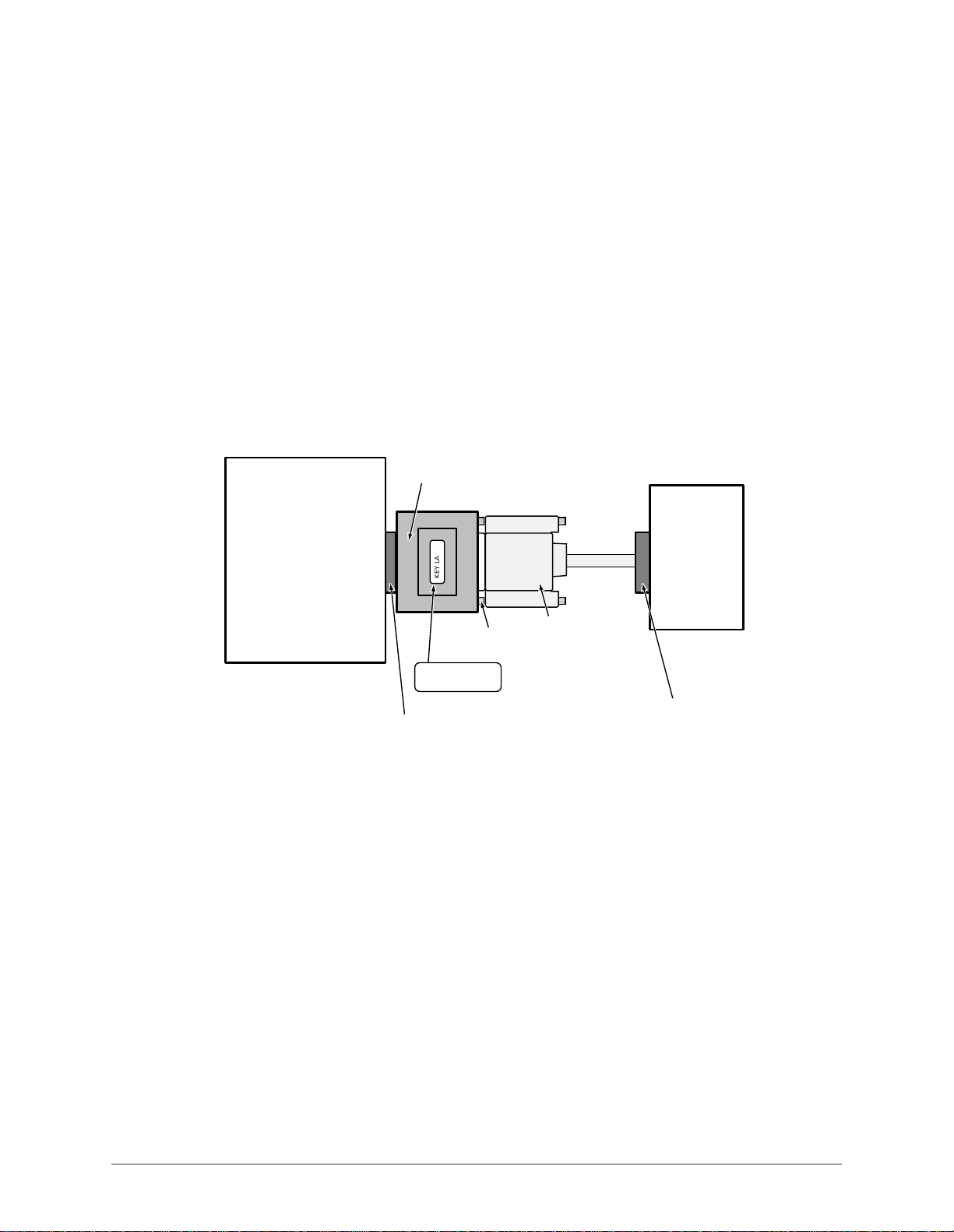
1. Install the DKAdmin hardware key (red) on the LPT1 parallel printer port as shown in
Figure 2.
Red DKAdmin Hardware Key (required for DKAdmin)
DKAdmin
IBM Compatible
Personal Computer
1994
KEY LABEL
4ELVCH-B
LPT1 Parallel Printer
Connector on Back
Parallel Printer
CableScrews
Printer
Parallel Printer Port
Figure 2 DKAdmin Hardware Connections
Notes
● If you wish, you can install a printer on the end of the LPT1 Admin Hardware Key.
● The printer can be installed and used on the LPT1/Admin Hardware Key. But, it is not
necessary to install a printer to enable DKAdmin to be installed or used.
2. Turn on your computer.
8
DKAdmin/DKBackup
Page 19

––––––––––––––––––––––––––––––––––––––––––––––––––––– Step 3: (Optional) Make Installation Floppy Disks
Step 3: (Optional) Make Installation Floppy Disks
From Windows
If you wish to install DKAdmin on a PC that does not have a CD- ROM, you will n eed t o make
installation floppies from a PC that has a CD-ROM. You can make installation disks that
install the program using a Wi ndows applic ation (thi s works on all PCs with Windows 3.x, 95,
98 or Windows NT) or you can make DOS only installation disks.
CAUTION! Do not use the DOS installation program on a Windows PC.
Note Be sure to exit all programs running in Windows before starting.
1. Insert the CD-ROM into your CD-ROM drive. The Main Menu appears.
...or if the Main Menu does not appear af ter you insert t he CD-ROM, clic k Start, Run, then
Browse. Select your CD-ROM drive from the Look in: pull down list. Locate and doubleclick mainmenu.exe. The Main Menu opens.
2. From the Main Menu, select “Make Floppy Installation Disks” then select “DKAdmin
Windows Installation Disks” or “DKAdmin DOS Installation Disks” (depending which
target PC will get the installation). Follow the prompts.
From DOS Only PC
If you wish to install DKAdmin on a PC that does not have a CD-ROM, we recommend that
you use a Windows PC and the preceding instructions to make installation floppy disks.
However, in the rare case you are using a DOS only PC that has a CD-ROM, follow these
steps:
1. Place a blank floppy in floppy drive A: (or B:). Insert the CD-ROM into your CD-ROM
drive. Change the DOS prompt to the CD-ROM drive letter and type:
cd\dkados\disk1 and press Enter.
2. Type: copy *.* A: (or B:) and press Enter.
3. Place a another floppy in floppy drive A: (or B:) and type: cd\dkados\disk2 and
press Enter.
4. Type: copy *.* A: (or B:) and press Enter.
Installing DKAdmin
9
Page 20

Step 4: Install DKAdmin –––––––––––––––––––––––––––––––––––––––––––––––––––––––––––––––––––––––––
Step 4: Install DKAdmin
DKAdmin is a DOS application program that can be installed and run in either DOS or as a
Windows DOS session.
CAUTION! If any earlier DKAdmin (280Admin) release is already installed on the PC,
do not delete it; install DKAdmin Release 4.XX over the existing DKAdmin
(280Admin) version as described below. DKAdmin is always installed in the
280Admin directory, overwriting the old DKAdmin (280Admin) operating
software but not customer database directories. Existing 280Admin
customer data can be used with DKAdmin Release 4.XX.
Note DKAdmin software is also available from the Toshiba FYI Internet site.
Windows PC from CD-ROM
Notes
● When installing DKAdmin to run as a DOS session in Windows NT, the install program
assumes that the default directory name (WINNT) and the default system drive (Drive C)
contain the system files. The installation procedure looks for this directory (C:\WINNT)
and, if found, copies the necessary drivers for Windows NT onto the hard disk.
● Be sure to exit all programs running in Windows before starting.
1. Insert the CD-ROM into your CD-ROM drive. The Main Menu appears.
...or if the Main Menu does not appear af ter you insert t he CD-ROM, clic k Start, Run, then
Browse. Select your CD-ROM drive from the Look in: pull down list. Locate and doubleclick mainmenu.exe. The Main Menu opens.
2. From the Main Menu, select “Install DKAdmin” and follow the prompts.
Important! Remember that the “Instal l DKAdmin” se lecti on in th e Main Menu is a Windows
application, but the actual DKAdmin application is a DOS/Windows DOS
session application.
Windows PC from Floppy Disks
Note Be sure to exit all programs before running the Setup program.
1. Insert Floppy Disk #1 i nto the fl oppy drive and click Start, th en Run. Type a:\setup (or
b:\setup). Click OK. Follow the prompts to install DKAdmin.
CAUTION! During installation, selecting “New Installation” overwrites the existing
DKAdmin customer list if you already have DKAdmin or 280Admin installed on your PC.
Although the customer list is overwritten, you can still retrieve the existing customer data
associated to that name by adding that customer’s name using the “Maintain Customer”
selection on the newly ins talle d DKAdmin. Do this for each customer name that is overwri tten
on the list.
10
2. Reboot your PC when prompted at the end of installation.
DKAdmin/DKBackup
Page 21

––––––––––––––––––––––––––––––––––––––––––––––––––––––––––––––––––––––––– Step 4: Install DKAdmin
Notes
● If you installed DKAdmin for the first time, a 280ADMIN directory was created and the
DKAdmin files copied to it.
● If you upgraded an existing DKAdmin program, your customer database has been
maintained in the 280ADMIN dir ectory.
DOS Only PC from CD-ROM
In the rare case your DOS only PC has a CD-ROM, follow these steps:
1. Insert the CD-ROM into your CD-ROM drive. Change the DOS prompt to that drive and
type: cd\dkados and press Enter.
Type: install and press Enter.
2. Go to Step 3 of the procedure entitled “DOS Only PC from Floppy Disks” below.
Disregard procedures refering to Disk #2.
CAUTION! During installation, selecting “New Installation” overwrites the existing
DKAdmin customer list if you already have DKAdmin or 280Admin installed on your PC.
Although the customer list is overwritten, you can still retrieve the existing customer data
associated to that name by adding that customer’s name using the “Maintain Customer”
selection on the newly ins talle d DKAdmin. Do this for each customer name that is overwri tten
on the list.
DOS Only PC from Floppy Disks
1. Insert the DKAdmin Disk #1 into drive A: (or B:).
2. Using DOS, type: a:\install (or b:\install) at the C: prompt and pre ss Enter.
The Toshiba Install DKAdmin System screen automatically displays. Follow the prompts
to install DKAdmin.
3. During installation, if you have an existing customer fi le i n an ol de r version of DKAdmin
(280Admin) on your PC, highlight the DKAdmin 4.0 Upgrade Installation
Only selection and press Enter.
...or if you are installing for the first time, highlight the DKAdmin 4.0 New
Installation selection and press Enter.
CAUTION! During installation, selecting “New Installation” overwrites the existing
DKAdmin customer list if you already have DKAdmin or 280Admin installed on your PC.
Although the customer list is overwritten, you can still retrieve the existing customer data
associated to that name by adding that customer’s name using the “Maintain Customer”
selection on the newly ins talle d DKAdmin. Do this for each customer name that is overwri tten
on the list.
4. Remove the floppy disk from your floppy disk drive and reset the PC to initialize the
changes made during installation.
5. Go to Step 3 in the “Run DKAdmin Program” on Page 12.
Notes
● If you installed DKAdmin for the first time, a 280ADMIN directory was created and the
Installing DKAdmin
DKAdmin files copied to it.
11
Page 22

Step 5: Run DKAdmin Program –––––––––––––––––––––––––––––––––––––––––––––––––––––––––––––––––––
● If you upgraded an existing DKAdmin program, your customer database has been
maintained in the 280ADMIN dir ectory.
● If your Config.sys file is changed and you have problems with the new file when you
reboot your computer, restore the original file (i.e., Config. bak).
Step 5: Run DKAdmin Program
Note Running the program und er Windows 95, 98 or Windows NT is r eco mmen ded for the
best performance.
Start-up DKAdmin under Windows 98, 95 or Windows NT 4.0
➤ Click on the DKAdmin icon. The Toshiba Title screen displays.
Start-up DKAdmin in MS-DOS
1. From the C:\ prompt, type CD 280ADMIN and press Enter.
2. From the C:\280ADMIN prompt, type dkadmin and press Enter. The Toshiba Title
screen displays.
Run DKAdmin
Note If the DKAdmin red hardware key is not installed, the following message displays:
1. Once the Toshiba Title screen displays, press any key to continue. This message appears:
Please Enter Your User ID:
2. Type Master and press Enter. This message appears: Please Enter Your
Password.
3. Type Master and press Enter. For security, your password does not display on the
screen as you type it.
The defaul t DKAdmin
Password File
Maintenance screen
displays (shown right).
It is recommended that
you change the MASTER
password and create any
other user passwords.
4. To change or add
passwords, see “User
Password Level Setup” on
Page 121.
Hardware key Not Installed. Exiting to DOS. OK. Install the
DKAdmin hardware key, then retry running the program.
12
5. After completing your password setup, press Esc. The message Do You Want To
Copy User File Back On The Installation Disk? displays.
DKAdmin/DKBackup
Page 23
––––––––––––––––––––––––––––––––––––––––––––––––––––––––––––––––––– Step 5: Run DKAdmin Program
6. Highlight Yes and pre ss Enter. If you choose No, yo ur new pa sswo rds are no t inst alle d
on the disk.
7. A “Copy to Drive” dialog box displays. The box defaults to drive A:. If you do not
want drive A:, type the drive lett er to which you wis h to copy the inst alla tion infor mation.
Press Enter. A dialog box displays asking you to insert the DKAdmin Installation Disk
#1 into the appropriate disk drive.
8. Insert DKAdmin Installation Disk #1 into the floppy-disk drive and press any key to
continue. When complete, a message Process Successful displays and your new
passwords are now available on your DKAdmin Installation Disk #1.
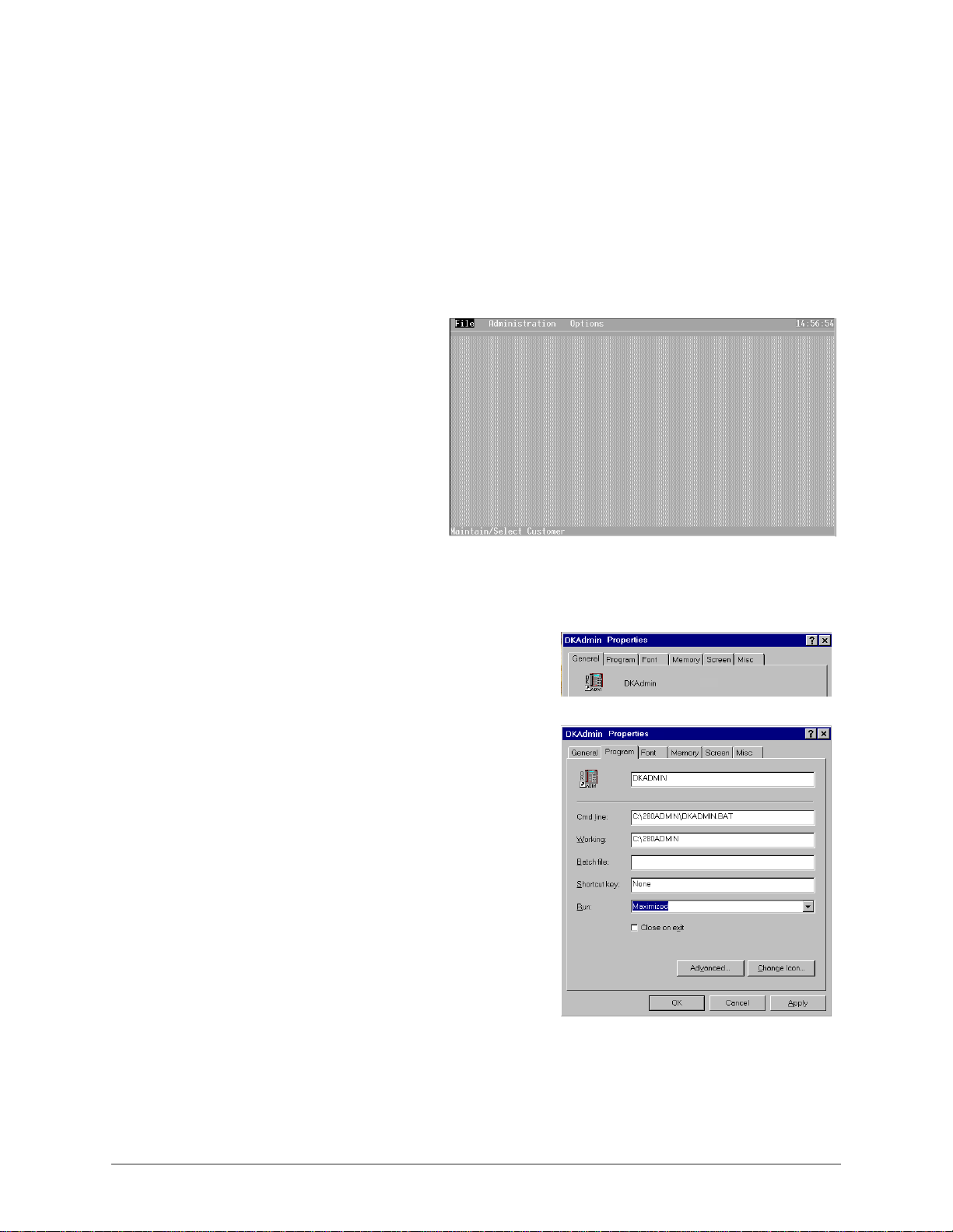
9. Press any key to display the
DKAdmin Main Menu
screen (shown right).
You are now ready to use
DKAdmin and can use your:
♦ Modified ins ta ll at ion
disks to install
DKAdmin on additional
workstations.
♦ New passwords to log in
to DKAdmin.
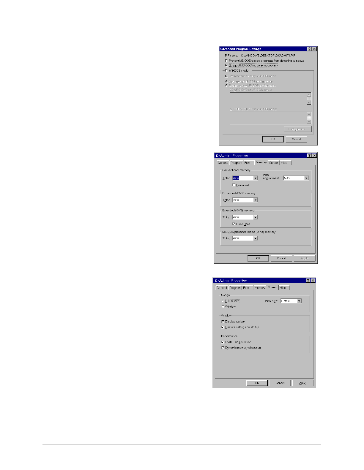
Set Windows DKAdmin Program Properties
Set these properties when running DKAdmin as a DOS session under Windows:
1. Right click on the DKAdmin desktop icon,
then click on Properties.
The DKAdmin Properties dialog box displays
(shown at right).
2. Select the Program Tab scree n (shown at
right). You should see:
Cmd line: C:\280ADMIN\DKADMIN.BAT
Working: C:\280ADMIN
3. In the Run box, select Maximized from the
drop-down menu.
4. Click Apply.
5. On the same screen, click Advanced. The
Advanced Program Settings screen displays.
Installing DKAdmin
13
Page 24
Step 5: Run DKAdmin Program –––––––––––––––––––––––––––––––––––––––––––––––––––––––––––––––––––
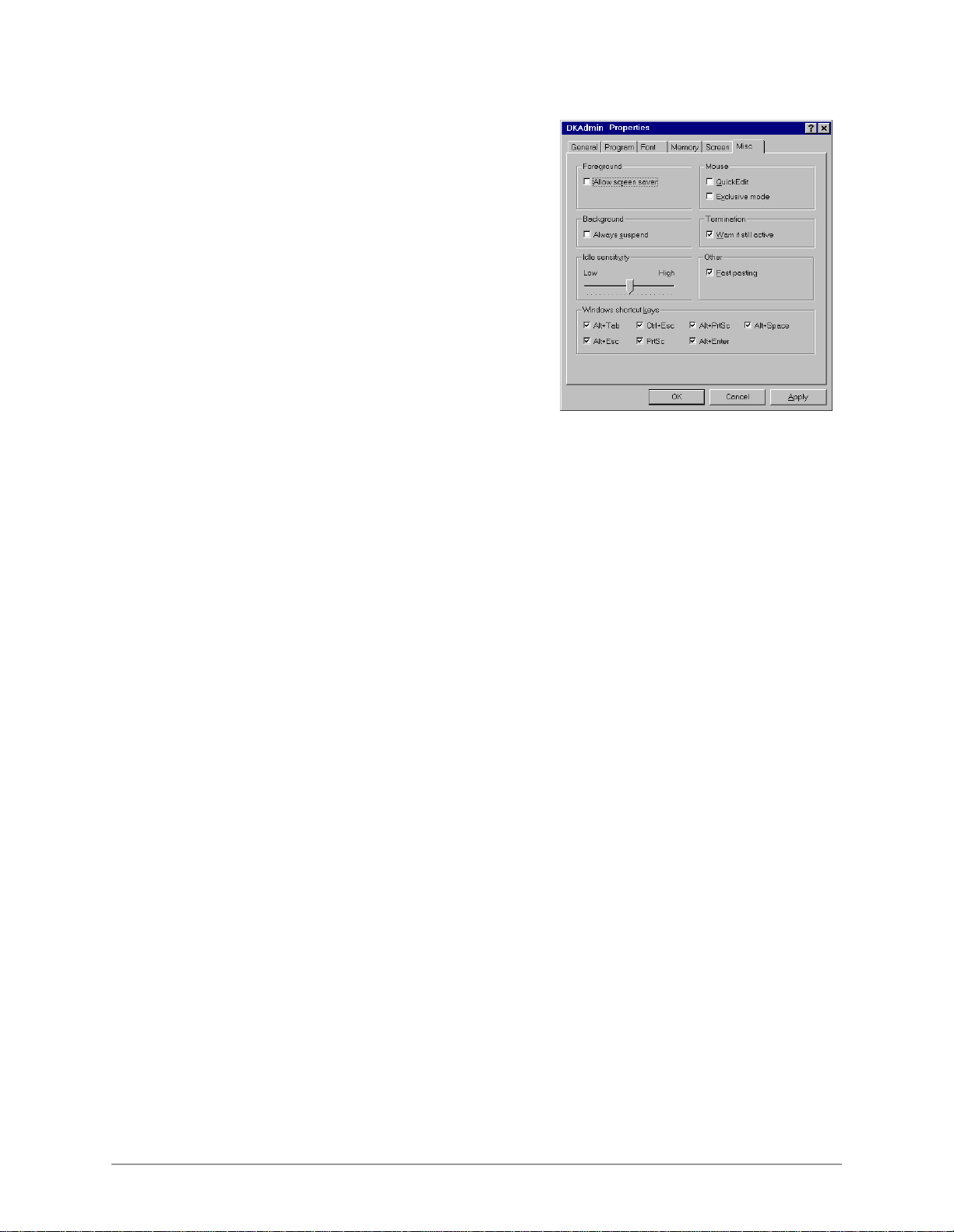
6. From Advanced Program Settings screen
(shown at right), check only the Suggest
MS-DOS mode as necessary option.
Click on OK.
Note Other screen sett ing s should not be selected.
7. Select the Memory Tab screen (shown at
right). All fields should read Auto. If you
make changes, click on OK.
14
8. Select the Screen Tab screen (shown at right).
The select ed settings sh ould be:
Usage: Full-screen
Window:
Display toolbar
Restore settings on startup
Performance:
Fast ROM emulation
Dynamic memory allocation
If you make changes, click on Apply.
DKAdmin/DKBackup
Page 25
–––––––––––––––––––––––––––––––––––––––––––––––––– Step 6: Connect to the Strata DK Telephone System
9. Select the Misc Tab screen (shown at right).
10. Only the items in the Termination, Other and
Windows shortcut keys boxes should be
selected.
NoteIt is best not to allow screen savers.
If you make changes, click on Apply.
11. Close the DKAdmin Properties dialog box
and return to Step 3 of “Start-up DKAdmin
under Windows 98, 95 or Windows NT 4.0”
on Page 12.
Step 6: Connect to the Strata DK Telephone System
➤ To program or update a Strata DK, you must be connected to the Strata DK telephone
system. For procedures on connecting your PC to the Strata DK, see Appendix A –
Connecting to Strata DK .
Installing DKAdmin
15
Page 26

Step 6: Connect to the Strata DK Telephone System –––––––––––––––––––––––––––––––––––––––––––––––––––
16
DKAdmin/DKBackup
Page 27

Installing DKBackup 3
Step 1: Check System Requirements
For optimum performance, run DKBackup on a personal computer with the following
minimum specifications:
♦ IBM-compatible 386/486 personal computer or higher level
♦ 20MB or larger hard drive
♦ CD-ROM or 3.5" 1.44KB high-density floppy drive
Note DKBackup software is distributed on a CD-ROM disk. Installation can be performed
using the CD-ROM disk or fro m fl oppy d isk(s ) copi ed f rom the CD-ROM DKBa ckup
install program.
♦ VGA or SVGA monitor preferred
♦ 640KB RAM (minimum)
♦ Microsoft MS-DOS 6.22, Windows 3.11 or higher (Windows 95, 98 or Windows
NT
4.0 recomm ended).
♦ A laser printer is reco mmended
♦ For network users, a minimum of 2MB of disk space is required for each person using
DKBackup on the network.
♦ DKBackup hardware key (green or red)
DKBackup is a MS-DOS program that can be installed and run under Microsoft
Windows 3.11, 95, 98, NT or MS-DOS (6.22 or higher)
. The instal lation and run instructions
in this chapter include both Windows and DOS installation information.
Important!
● If your PC has Windows installed, setting your Windows SYSTEM.INI and DOS
CONFIG.SYS files with the commands below may help DKBackup run on your PC.
SYSTEM.INI
[NonWindowsApp]
COMMANDENVSIZE=1024
DOS CONFIG.SYS
SHELL=C:\COMMAND.COM /e:1024 /p
● If DKBackup display s a “Run time e rror” message dur ing in stall ation or ope ration , erase
Installing DKBackup
all “ntx” files under the customer directory (XXX.DK) and the “data” directory.
17
Page 28

Step 2: Power Up DKBackup PC ––––––––––––––––––––––––––––––––––––––––––––––––––––––––––––––––––
● From C:\280BCKUP\Data, type del *.ntx and press Enter.
● From C:\280BCKUP\XXX.DK, type del *.ntx and press Enter.
● Run “ReIndex Files” under Options/System Utilities Menu each time before you start to
use DKBackup.
● Always exit DKBackup before you turn your computer off.
Step 2: Power Up DKBackup PC
Note The DKBackup or DKAdmin Hardware Key must be installed on the PC LPT1 port,
to allow the DKBackup program to be used after it is installed. If you install
DKBackup without the key, it will not run.
1. Install the DKBackup hardware key (green or red) on the LPT1 parallel printer port as
shown in Figure 3.
DKBackup Hardware Key
(Teal green or red color required for DKBackup)
DKBackup
IBM Compatible
Personal Computer
1049
LPT1 Parallel Printer
Connector on Back
Figure 3 DKBackup Hardware Connections
Notes
● If you wish, you can install a printer on the end of the LPT1 Admin Hardware Key.
● The printer can be installed and used on the LPT1/Backup Hardware Key. But, it is not
necessary to install a printer to enable DKBackup to be installed or used.
2. Turn on your computer.
KEY LABEL
Parallel Printer
CableScrews
(Green) (Red)
4DGFCH-B 4ELVCH-B
or
Printer
Parallel Printer Port
18
DKAdmin/DKBackup
Page 29

––––––––––––––––––––––––––––––––––––––––––––––––––––– Step 3: (Optional) Make Installation Floppy Disks
Step 3: (Optional) Make Installation Floppy Disks
From Windows
If you wish to install DKBackup on a PC that does not have a CD-ROM, you will need to
make installation f loppies from a PC that has a CD-ROM. You can make installation dis ks that
install the program using a Windows applic ation (this work s on all PCs with Windows 3.x, 95,
98 or Windows NT) or you can make DOS only installation disks.
CAUTION! Do not use the DOS installation program on a Windows PC.
Note Be sure to exit all programs running in Windows before starting.
1. Insert the CD-ROM into your CD-ROM drive. The Main Menu appears.
...or if the Main Menu does not appear af ter you insert t he CD-ROM, clic k Start, Run, then
Browse. Select your CD-ROM drive from the Look in: pull down list. Locate and doubleclick mainmenu.exe. The Main Menu opens.
2. From the Main Menu, select “Make Floppy Installation Disks” then select “DKBackup
Windows Installation Disks” or “DKBackup DOS Installation Disks” (depending which
target PC will get the installation). Follow the prompts.
From DOS Only PC
If you wish to install DKBackup on a PC that does not have a CD-ROM, we recommend that
you use a Windows PC and the preceding instructions to make installation floppy disks.
However, in the rare case you are using a DOS only PC that has a CD-ROM, follow these
steps:
1. Place a blank floppy in floppy drive A: (or B:). Insert the CD-ROM into your CD-ROM
drive. Change the DOS prompt to the CD-ROM drive letter and type:
cd\dkbdos\disk1 and press Enter.
2. Type: copy *.* A: (or B:) and press Enter.
3. Place a another floppy in floppy drive A: (or B:) and type: cd\dkbdos\disk2 and
press Enter.
4. Type: copy *.* A: (or B:) and press Enter.
Installing DKBackup
19
Page 30

Step 4: Install DKBackup ––––––––––––––––––––––––––––––––––––––––––––––––––––––––––––––––––––––––
Step 4: Install DKBackup
DKBackup is a DOS application program that can be installed and run in either DOS or as a
Windows DOS session.
CAUTION! If any earlier DKBackup (280Backup) re lease is al r eady ins talle d on the PC,
do not delete it; insta ll DKBackup Release 4.XX ove r the existing DKBac kup
(280Backup) version as described below. DKBackup is always installed in
the 280Backup directory, overwriting the old DKBackup (280Backup)
operating software but not customer database directories. Existing
280Backup customer data can be used with DKBackup Release 4.XX.
Note DKBackup software is also available from the Toshiba FYI Internet site.
Windows PC from CD-ROM
Notes
● When installing DKBackup to run as a DOS session in Windows NT, the install program
assumes that the default directory name (WINNT) and the default system drive (Drive C)
contain the system files. The installation procedure looks for this directory (C:\WINNT)
and, if found, copies the necessary drivers for Windows NT onto the hard disk.
● Be sure to exit all programs running in Windows before starting.
1. Insert the CD-ROM into your CD-ROM drive. The Main Menu appears.
...or if the Main Menu does not appear af ter you insert t he CD-ROM, clic k Start, Run, then
Browse. Select your CD-ROM drive from the Look in: pull down list. Locate and doubleclick mainmenu.exe. The Main Menu opens.
2. From the Main Menu, select “Install DKBackup” and follow the prompts.
Important! Remember that the “Install DKBackup” selection in the Main Menu is a
Windows application, but the actual DKBackup application is a DOS/Windows
DOS session application.
Windows PC from Floppy Disks
Note Be sure to exit all programs before running the Setup program.
1. Insert Floppy Disk #1 i nto the fl oppy drive and click Start, th en Run. Type a:\setup (or
b:\setup). Click OK. Follow the prompts to install DKBackup.
CAUTION! During installation, selecting “New Installation” overwrites the existing
DKBackup customer list if you already have DKBackup or 280Backup installed on your PC.
Although the customer list is overwritten, you can still retrieve the existing customer data
associated to that name by adding that customer’s name using the “Maintain Customer”
selection on the newl y installed DKBackup. Do this f or each customer name that is overwr itten
on the list.
20
2. Reboot your PC when prompted at the end of installation.
DKAdmin/DKBackup
Page 31

–––––––––––––––––––––––––––––––––––––––––––––––––––––––––––––––––––––––– Step 4: Install DKBackup
Notes
● If you installed DKBackup for the first time, a 280BCKUP directory was created and the
DKBackup files copied to it.
● If you upgraded an existing DKBackup program, your customer database has been
maintained in the 280BCKUP directory.
DOS Only PC from CD-ROM
In the rare case your DOS only PC has
a CD-ROM, follow these steps:
1. Insert the CD-ROM into your CDROM drive. Change the DOS prompt to that drive and type: cd\dkados and press
Enter.
Type: install and press Enter.
2. Go to Step 3 of the procedure
entitled “DOS only PC from Floppy Disks” below. Disregard procedures refering to Disk
#2.
CAUTION! During installation,
selecting “New Installation” overwrites the existing DKBackup customer list if you already
have DKBackup or 280Backup i nstalled on your PC. Although th e customer list i s overwritten,
you can still retrieve the existing customer data associated to that name by adding that
customer’s name using the “Maintain Customer” selection on the newly installed DKBackup.
Do this for each customer n am e that is overwritten on the list.
DOS only PC from Floppy Disks
1. Insert the DKBackup Disk #1 into drive A: (or B:).
2. Using DOS, type: a:\install (or b:\install) at the C: prompt and pre ss Enter.
The T os hiba I nstal l DKBackup Sys tem scr een aut omatica lly di splays . Follow t he prompt s
to install DKBackup.
3. During installation, i f you have an existing customer fil e in an older version of DKBackup
(280Backup) on your PC, highlight the DKBackup 4.0 Upgrade Installation
Only selection and press Enter.
...or if you are installing for the first time, highlight the DKBackup 4.0 New
Installation selection and press Enter.
CAUTION! During installation, selecting “New Installation” overwrites the existing
DKBackup customer list if you already have DKBackup or 280Backup installed on your PC.
Although the customer list is overwritten, you can still retrieve the existing customer data
associated to that name by adding that customer’s name using the “Maintain Customer”
selection on the newl y installed DKBackup. Do this f or each customer name that is overwr itten
on the list.
4. Remove the floppy disk from your floppy disk drive and reset the PC to initialize the
changes made during installation.
5. Go to Step 3 in the “Run DKBackup” on Page 22.
Installing DKBackup
21
Page 32

Step 5: Run DKBackup Program ––––––––––––––––––––––––––––––––––––––––––––––––––––––––––––––––––
Notes
● If you installed DKBackup for the first time, a 280BCKUP directory was created and the
DKBackup files copied to it.
● If you upgraded an existing DKBackup program, your customer database has been
maintained in the 280BCKUP directory.
● If your Config.sys file is changed and you have problems with the new file when you
reboot your computer, restore the original file (i.e., Config. bak).
Step 5: Run DKBackup Program
Note Running the program und er Windows 95, 98 or Windows NT is r eco mmen ded for the
best performance.
Start-up DKBackup under Windows 3.11, 95, 98 or Windows NT 4.0
➤ Click on the DKBackup icon. The Toshiba Title screen displays.
Start-up DKBackup in MS-DOS
1. From the C:\ prompt, type CD 280BCKUP and press Enter.
2. From the C:\280BCKUP prompt, type dkbackup and press Enter. The Toshiba Title
screen displays.
Run DKBackup
Note If the DKBackup red or green hardware key is not installed, the following message
1. Once the Toshiba Title screen displays, press any key to continue. This message appears:
Please Enter Your User ID:
2. Type Master and press Enter. This message appears: Please Enter Your
Password.
3. Type Master and press Enter. For security, your password does not display on the
screen as you type it.
The defaul t DKBackup
Password File
Maintenance screen
displays (shown right).
It is recommended that
you change the MASTER
password and create any
other user passwords.
displays: Hardware key Not Ins talled. Exiting to DOS. OK. Install
the DKBackup hardware key, then retry running the program.
22
4. To change or add
passwords, see “User
Password Level Setup” on
Page 121.
DKAdmin/DKBackup
Page 33

–––––––––––––––––––––––––––––––––––––––––––––––––––––––––––––––––– Step 5: Run DKBackup Program
5. After completing your password setup, press Esc. The message Do You Want To
Copy User File Back On The Installation Disk? displays.
6. Highlight Yes and press Enter . If you ch oose No, yo ur new passwo rds ar e not i nstal led
on the disk.
7. A “Copy to Drive” dialog box displays. The box defaults to drive A:. If you do not
want drive A:, type the drive lett er to which you wis h to copy the inst alla tion infor mation.
Press Enter. A dialog box displays asking you to insert the DKBackup Installation Disk
into the appropriate disk drive.
8. Insert the DKBackup Installation Disk into the floppy-disk drive and press any key to
continue. When complete, a message Process Successful displays and your new
passwords are now available on your DKBackup Installation Disk.
9. Press any key to display
the DKBackup Main Menu
screen (shown right).
You are now ready to use
DKBackup and can use
your:
♦ Modified ins ta ll at ion
disks to install
DKBackup on
additional
workstations.
♦ New passwords to log
in to DKBackup.
Set Windows DKBackup Program Properties
1. Right click on the DKBackup desktop icon,
then click on Properties.
The DKBackup Properties dialog box di splays
(shown at right).
2. Select the Program Tab scree n (shown at
right). You should see:
Cmd line: C:\280BCKUP\DKBCKUP.BAT
Working: C:\280BCKUP
3. In the Run box, select Maximized from the
drop-down menu.
4. Click Apply.
5. On the same screen, click Advanced. The
Advanced Program Settings screen displays.
Installing DKBackup
23
Page 34

Step 5: Run DKBackup Program ––––––––––––––––––––––––––––––––––––––––––––––––––––––––––––––––––
6. From Advanced Program Settings screen
(shown at right), check only the Suggest
MS-DOS mode as necessary option.
Click on OK.
Note Other screen sett ing s should not be selected.
7. Select the Memory Tab screen (shown at
right). All fields should read Auto. If you
make changes, click on OK.
24
8. Select the Screen Tab screen (shown at right).
The select ed settings sh ould be:
Usage: Full-screen
Window:
Display toolbar
Restore settings on startup
Performance:
Fast ROM emulation
Dynamic memory allocation
If you make changes, click on Apply.
DKAdmin/DKBackup
Page 35

–––––––––––––––––––––––––––––––––––––––––––––––––– Step 6: Connect to the Strata DK Telephone System
9. Select the Misc Tab screen (shown at right).
10. Only the items in the Termination, Other and
Windows shortcut keys boxes should be
selected.
NoteIt is best not to allow screen savers.
If you make changes, click on Apply.
11. Close the DKBackup Properties dialog box
and return to Step 3 of “Start-up DKBackup
under Windows 3.11, 95, 98 or Windows NT
4.0” on Page 22.
Step 6: Connect to the Strata DK Telephone System
➤ To program or update a Strata DK, you must be connected to the Strata DK telephone
system. For procedures on connecting your PC to the Strata DK, see Appendix A –
Connecting to Strata DK .
Installing DKBackup
25
Page 36

Step 6: Connect to the Strata DK Telephone System –––––––––––––––––––––––––––––––––––––––––––––––––––
26
DKAdmin/DKBackup
Page 37

Using DKAdmin/DKBackup 4
This chapter shows you how to log on and off DKAdmin/DKBackup, use the pull-down
menus and select system options, respond to system and error messages, and describes the
keyboard conventions used in the programs.
Before You Start
Before using DKAdmin/DKBackup, you must:
♦ Connect your personal computer to a Strata DK in order to send/receive data between the
DKAdmin/DKBackup PC and a Strata DK (see Appendix A – Connecting to Strata DK
for procedures).
♦ Properly install the DKAdmin/DKBackup hardware key (see Chapter 2 – Installing
DKAdmin and Chapter 3 – Installing DK Backup for procedures).
♦ Correctly set your communications (see Chapter 8 – Options Menu).
Logging On
DKAdmin
➤ To log on to DKAdmin
1. After powering up your
computer, at the C:\
prompt type CD
280ADMIN and press
Enter.
2. From the C:\280ADMIN
prompt, type dkadmin
and press Enter. The
Toshiba start-up page
displays (shown right).
3. Type your User ID and
press Enter.
4. Type your password and
press Enter.
Using DKAdmin/DKBackup
27
Page 38

Logging On –––––––––––––––––––––––––––––––––––––––––––––––––––––––––––––––––––––––––––––––––––
If you have entered
your User ID and
password correctly , the
DKAdmin Main Menu
displays (shown right).
All DKAdmin activity
originates from the
DKAdmin Main
Menu.
The three items across
the DKAdmin Main
Menu bar (i.e., File,
Administration,
Options) enable you to perform the many functions shown in Figure 5. Some items may
not be available for selection, depending on your assigned User ID and password. The
menus shown here depict DKAdmin Master password Level 9 options.
Important! It is recommended to run “ReIndex Files” each time you start to use DKAdmin/
DKBackup. If files are not indexed correctly you may encounter problems using
some functions of DKAdmin/DKBackup.
28
DKAdmin/DKBackup
Page 39

––––––––––––––––––––––––––––––––––––––––––––––––––––––––––––––––––––––––––––––––––– Logging On
File
Administration
Select Customer
Maintain Customer File
Dial DK
Hangup Connection
Transfer DK Data
About
Exit
View Cabinet Diagram
Check Processor Type
System/Station Administration
Flexible Key Programming Section
Speed Dial Programming Section
ACD Administration Section
Program Administration Section
Security Maintenance Section
Directory Number Administration
DNIS Administration
Distributed Hunt Group
Administration
Call Forward Assignments
E911/CAMA Trunk Programs
(R4 Only)
ISDN Programs (R4 Only)
Backup/Restore Data
View/Print Data
Telephone Flexible Button Assignments
Add-on Module Button Assignments
DSS Console Button Assignments
Attendant Console Flexible Button Assignments
System Speed Dial Numbers
Station Speed Dial Numbers
ACD Programs
ACD Agent Programs
View All Programs
View System Features by Subject
System Number Plan & Port Locations
System Wide Option Programs
Station Options Programs
Station (Gnd/Loop) Co Line Assignment
Programs
Station Group Programs
Security/Account/T.R. Ovr. Programs
Voice Mail Integration Programs
ACD Programs
ACD Agent Programs
DK Auto Attendant Programs
Attendant Console Programs
T1 Programs
Ground/Loop Start CO Line Programs
DID/Tie Line Programs
IMDU or RMDS Modem/DID/DNIS
Assignment
Toll Restriction Programs
Data Interface Unit Programs
Doorphone/Ext. Paging/BGM/Conference
LCR Programs
Multiple Directory Number Programs
ANI Programs
DNIS Programs
DKT/RPCI/OA Interface Programs
Class/Caller ID Programs
Distributed Hunt Programs
Call Park Programs
Off Hook Call Announce Programs
Standard Telephone MW/Camp-on Tone
Programs
Enhanced 911 Programs
ISDN Programs
Initialization Programs
Options
System Installation
Systems Utilities
Figure 4 DKAdmin Main Menu Options
Using DKAdmin/DKBackup
DNIS/DID/ANI Line Assignments
DNIS Number/Name/Ringing/VM-ID
Assignments
DNIS Network Table Assignments
DNIS Tenant Lock Assignments
Company General Information
Screen Type/Color Installation
Printer Type Selection
System Miscellaneous Variables
User Password Level Setup
Communications Setup
ReIndex Files
1089
29
Page 40

Logging On –––––––––––––––––––––––––––––––––––––––––––––––––––––––––––––––––––––––––––––––––––
DKBackup
➤ To log on to DKBackup
1. After powering up
your computer, at the
C:\ prompt type
CD 280BCKUP and
press Enter.
2. From the
C:\280BCKUP
prompt, type
dkbckup and press
Enter. The Toshiba
start-up page displays
(shown right).
3. T ype your User ID an d
press Enter.
4. Type your password
and press Enter.
If you have entered your User ID and password correctly, the DKBackup Main Menu
displays (shown right).
All DKBackup activity
originates from the
DKBackup Main
Menu.
The three items across
the DKBackup Main
Menu bar (i.e., File,
Backup, Options)
enable you to perform
the many functions
shown in Figure 5.
Some items may not
be available for
selection, depending
on your assigned User ID and password. The menus shown here depict DKBackup Master
password Level 9 options.
30
DKAdmin/DKBackup
Page 41

–––––––––––––––––––––––––––––––––––––––––––––––––––––––––––––––––––––––––– Keyboard Conventions
File
Backup
Options
Select Customer
Maintain Customer File
Dial DK
Hangup Connection
Transfer DK Data
About
Exit
Check Processor Type
Backup/Restore Data
View/Print Data
System Installation
Systems Utilities
Screen Type/Color Installation
Printer Type Selection
System Miscellaneous Variables
User Password Level Setup
Communications Setup
ReIndex Files
1088DK
Figure 5 DKBackup Main Menu Options
Keyboard Conventions
While working within DKAdmin/DKBackup, you can use the following keys to:
Esc
Page Up/Page Down Moves to the previous/next questions screen.
Enter Executes a screen selection/transaction.
Left/Right Arrow Moves the selection highlighter left/right.
Up/down Arrow Moves the selection highlighter up/down.
Spacebar Depending on the screen, toggles between selections
Escapes from the current screen/menu and returns you
to the previous screen/menu.
for the field or selects the list item and places a check
mark next to it.
Using DKAdmin/DKBackup
31
Page 42

Using the Pull-Down Men us ––––––––––––––––––––––––––––––––––––––––––––––––––––––––––––––––––––––
Using the Pull-Down Menus
You can perform all basic operation s from the Main
Menu’s menu bar. When you select an item in the menu
bar, a “pull-down” options menu appears, listing all the
functions which you can perform (shown right).
➤ To use a pull-down menu
1. Use the left/right arrow keys to highlight the item
and press Enter. Or, if you prefer, you can type the
highlight ed letter for the item you wi sh to “pull
down”:
F=File
B = Backup
O = Options
2. Once in a pull-down menu, you can use the same
keyboard conventions you do to make a menu
selection (use the up/down arrow keys or type the highlighted letter).
3. To close a menu, press Esc.
System Messages
At the bottom of each DKAdmin/DKBackup screen is a message line (see Page 5). Pay
particular att ention t o this li ne as you work , since it displ ays import ant syste m infor mation and
processing options for the application or screen in which you are currently working.
Error Messages
If you make an incorrect entry while working in DKAdmin/DKBackup, you are sometimes
prompted with an error mess age. This tell s you why DKAdmin/ DKBack up cannot proces s the
attempted transaction. By reviewing the error message, you will be able to determine your
error and su ccessfully execute the desired trans action.
On-Line Help
DKAdmin/DKBackup offers you on-l ine help for many syste m operatio ns. Should you hav e a
question, press F1 (F1-Help must appear at the bottom of the screen to be active) to display
an explanation of t he operat ion in wh ich you ar e curren tly worki ng. To close the Help window ,
press Esc.
32
DKAdmin/DKBackup
Page 43

––––––––––––––––––––––––––––––––––––––––––––––––––––––––––––––––––––––––––––––––––– Logging Off
Logging Off
➤ To exit the DKAdmin/DKBackup system
1. Return to the DKAdmin/DKBackup Main Menu by pressing Esc until the Main Menu
displays.
2. Highlight the File Menu option and press Enter, or type f.
3. Highlight Exit and press Enter, or type x.
DKAdmin/DKBackup shuts down and returns the screen to a DOS prompt.
CAUTION! Always exit the program properly before turning off your DKAdmin/
DKBackup PC. Turning off your PC before exiting the program, creates an
indexing problem and pr oduces run -time err ors. (See Pag e 7 for information
on correcting run-time errors.)
Using DKAdmin/DKBackup
33
Page 44

Logging Off –––––––––––––––––––––––––––––––––––––––––––––––––––––––––––––––––––––––––––––––––––
34
DKAdmin/DKBackup
Page 45

File Menu 5
This chapter gives you step-by-step instructions on using the options available on the File
Menu. The options are:
♦ Sele ct Cust omer
♦ Maintain Customer File
♦ Dial DK
♦ Hangup Connection
♦ Transfer DK Data
♦ About
♦ Exit
Quick-start Procedures for Using DKAdmin
For an Existing Customer
➤ To quickly use DKAdmin with a previously programmed Strata DK
1. Create a new customer record, using the Maintain Customer File option from the File
Menu.
2. Select the newly created customer, using the Select Customer option from the File Menu.
3. If you will be Uploading/Downloading data between the DKAdmin PC and a Strata DK
and you must dial via modem or Toshiba DIU to connect, use th e Dial DK optio n to sele ct
and dial the customer; or, connect the DKAdmin PC directly to the DK system (see
Appendix A – Connecting to Strata DK).
4. When the DKAdmin PC first connects to the Strata DK, verify that the selected customer
processor is the same type as the one installed in the DK system. Highlight the Check
Processor Type option under the Administration Menu and press Enter. Enter the
applicable DK code. The St rata DK se nds the proces sor t ype and versi on to t he DKAdmin
PC.
5. Back up (download) the customer’s original data using the
from the Backup/Restore Data option under the Administ ration Menu.
6. Update the customer DK data, using options from the Administration Menu.
Backup option (F2) and (F3)
File Menu
7. Restore (upload) the new data to the customer’s Strata DK, using the Restore option (F2)
and (F4) from the Backup/Restore Data option under the Administration Menu.
35
Page 46

Maintain Customer File ––––––––––––––––––––––––––––––––––––––––––––––––––––––––––––––––––––––––––
For a New Customer
➤ To quickly use DKAdmin with a new installation of Strata DK
1. Create a new customer record, using the Maintain Customer File option from the File
Menu.
2. Select the newly created customer, using the Select Customer option from the File Menu.
3. Program the customer DK data, using the ACD Administration Section and Program
Administration Section options from the Administration Menu.
4. Dial the Strata DK, using the Dial DK option from the File Menu, or connect the
DKAdmin PC directly to the Strata DK (see Appendix A – Connecting to Strata DK).
5. When the DKAdmin PC first connects to the Strata DK, verify that the selected customer
processor is the same t ype inst alled in t he DK sy stem. Highlig ht th e Check Pro cessor Type
option in the Administration Menu and press Enter. Enter the applicable DK code. The
Strata DK sends the processor type and version to the DKAdmin PC.
6. Initialize the Strata DK processor PCB by running Program 91-9 from the Initialization
Programs option located in the Program Administration Menu (this option will interrupt
service and drop all calls).
Note If initializing from a remote loc ation, the DKAdmin PC must be connected to the
Strata DK via modems as shown in Figure 18 on Page 132 only.
7. Restore (upload) the new data to the customer’s Strata DK, using the Restore option (F2)
and (F4) from the Backup/Restore Data option in the Administration Menu.
Maintain Customer File
Using this option, you can insert a new customer, review and updat e a customer’ s inf ormation,
delete a customer or upgrade a customer’s processor.
Note In the procedures for u pgr ading a customer’s processor, t he wor d “o ri ginal” describes
the existing processor and “new” describes the upgraded processor.
➤ To access the Maintain Customer File option
1. Type m and the Customer
List displays (shown
right).
The list shows each
customer’s ID, name,
assigned directory, and
the last date the
customer’s Strata DK
data was downloaded
and uploaded. If
upgrading a processor,
you should always crea te
a new customer,
selecting the “original” processor (e.g., RCTUA,B, C/D, E/F) and the original software
release (1, 2, 3 or 4).
36
DKAdmin/DKBackup
Page 47

–––––––––––––––––––––––––––––––––––––––––––––––––––––––––––––––––––––––––– Maintain Customer File
➤ To create a customer record or upgrade a customer’s processor
1. Press Ins to insert a
record. A blank
Customer File
Maintenance Screen
displays (shown right).
2. See Table 2 for a
description of the
fields on th is screen.
Press Enter after
each entry.
Table 2 Customer File Maintenance Screen Fields
Field Description
Customer ID Enter a unique customer ID, using up to eight alphanumeric characters. If you
Customer Name Enter the full customer name.
Address Enter the customer’s street address.
Address The second address line may be used to enter a suite or PO number.
City, State, Zip Enter the customer’s city, state and ZIP code.
Country Code Enter the three character country code.
Contact Name Enter a contact name, as applicable.
Country Ph. Code Enter the three character foreign country telephone code.
Phone No., Ext Enter the customer telephone number (of the customer contact), including area
DIU String The first part of the DIU string is automatically entered. You must enter the
Modem Dial String Enter the complete mo dem string number when mo dem s a re us ed to c onn ec t to:
attempt to enter an existing customer ID code, the system displays an error
message: Record exists.
code, and extension. This telephone number does not automatically dial out
when using the Dial DK option and is only used as a reference for the customer
telephone number.
extension number (XXXX) of the DIU (modem pool or TTY PDIU-DS) after the
ATDD option. This string is used when DIUs are used to connect DKAdmin/
DKBackup to the DK TTY port (see Figure 18 on Page 132 and Figure 20 on
Page 135). The DIU String is sent to the DIU when pressing F2 or F3 from the
Custom List screen of the Dial DK option.
an external modem connected to the TTY port, or the RMDS or IMDU built-in
modems (see Figures 18 ~ 22 on Pages 132 ~ 139). This string is sent when
using (F3)–DID/DIU/modem, (F4)–modem initial + modem dial string, or (F5)–
modem dial string only .
File Menu
37
Page 48

Maintain Customer File ––––––––––––––––––––––––––––––––––––––––––––––––––––––––––––––––––––––––––
Table 2 Customer File Maintenance Screen Fields
(continued)
Field Description
After Connect
Enter the After Connect String when calling into a Strata DK modem pool (see
Figure 20 on Page 135). It is recommended that you enter AT~~~ATDDYYY as
the After Connect string (where YYY is the extension number of the PDIU-DS
connected to the Strata DK TTY port).
Notes
● If you are not using the modem pool function, the DK security code can be set
on the After Connect line in each Customer File setup so it will be sent
automatically to the Strata DK after connecting the DKAdmin/DKBackup PC to
the Strata DK remotely via modems. Setting the DK security code in the After
Connect String is optional.
● In some cases, when conn ecting to older R elease 1 processors or during heavy
traffic conditions, the After Connect string may be sent and not recognized by
the Strata DK. If this shou ld occur, do not enter the DK s ecurity c ode in the Af ter
Connect string.
DK Model, Release Press Enter and the DK Model, Release dialog box appears. Highlight the
appropriate processor type and software release number and press Enter.
DK14, WMAU, R1
DK16e, TMAU , R1
DK40, TMAU, R1
DK , RCTU-A, R1/R2
DK , RCTU-A, R3.1
DK , RCTU-A, R4
DK , RCTU-B, R1/R2
DK , RCTU-B, R3
DK , RCTU-B, R4
DK , RCTU-CD, R1/R2
DK , RCTU-CD, R3
DK , RCTU-CD, R4
DK , RCTU-EF, R3
DK , RCTU-EF, R4
Important!
●
For proper operation, be sure you select the appropriate software release.
●
If creating a new customer to upgrade a processor, select the current release
level (i.e., if upgrading from RCTUB2, select Release 2).
●
To upgrade a Release 1 or Release 2 processor to Release 3 or Release 3.10,
select Release 1 or 2; the upgrade process converts this line to Release 3.
●
To upgrade Release 3 to Release 3.10 processors, select Release 3.
Data Directory The customer directory automatically defaults to the assigned customer ID. You
may change the directory as desired. This is the directory in which all customer
data is stored on the DKAdmin/DKBackup PC disk drive. DKAdmin/DKBackup
automatically adds the “.DK” extension on the end of the directory.
38
DKAdmin/DKBackup
Page 49

––––––––––––––––––––––––––––––––––––––––––––––––––––––––––––––––––––––––––––––– Sele ct Cus tom er
Table 2 Customer File Maintenance Screen Fields
Field Description
280BCKUP 1.0
Conversion Directory
Note See Appendix A – Connecting to Strata DK for DIU, modem, and After Connect dial
If you chose “Upgrade I nst all ati on O nl y” w hen ins tal lin g the DK Adm in/D KBa ck up
program, this field appears on your screen. It is no longer supported by the
programs and should not be used.
settings.
3. When you have finished, press Enter to scroll to the bottom of the screen. Press Enter
again to save the information. DKAdmin/DKBackup creates the necessary default DK
files for this processor type and customer. When complete, the new customer has been
added alphabetically by the Customer ID to the customer list and the DKAdmin/
DKBackup Main Menu is displayed.
Note If upgrading a processor, select the original processor from which you are upgrading.
For example, if you are upgrading from RCTUB to RCTU C/D, select RCTUB.
➤ To modify a customer record
1. Highlight a customer, press Enter and the Customer File Maintenance screen displays.
2. Use the up/down arrow keys to highlight a field and update the information.
3. When you have changed the information, press Enter to scroll to the bottom of the
screen. Press Enter again to save the information or Esc to exit without saving your
changes.
(continued)
➤ To delete a customer record
1. Highlight a customer, and press Del. A Delete Record confirmation window appears on
the screen.
2. Highlight Yes, press Enter, and the customer is deleted from the Customer List.
3. Press Esc to clos e the Cus tomer List scree n and retur n to the DKAdmi n/DKBackup Main
Menu.
Select Customer
Important! Before y ou can use any of the opt ions in the Backup Menu , you must firs t se lect a
customer. If you attempt to select an option from the menu without first selecting
a customer, the following message display s: Please select a customer
first!
➤ To select a customer
1. Type f and the Select Customer option is highlighted.
Important! If you are uploading/downloading data between the DKAdmin/DKBackup PC
and a Strata DK an d you must dial via modem or Toshiba DIU to connect, use the
Dial DK option to select and dial the customer. If the PC is connected directly to
the Strata DK, use the Select Customer option (not the Dial DK option) to select
the customer (see Appendix A – Connecting to Strata DK).
File Menu
39
Page 50

Dial DK ––––––––––––––––––––––––––––––––––––––––––––––––––––––––––––––––––––––––––––––––––––––
2. Press Enter and the Customer List displays.
3. Highlight the desired customer, and press Enter. The DKAdmin/DKBackup Mai n Menu
displays.
Note If you have multiple customers, you can use the Find function to move quickly to
another customer by typing the first letter of the Customer ID number. The program
highlights the first customer which matches your entry. Press Enter to select the
highlighted customer or re-enter.
After selecting a customer, the bottom of the DKAdmin/DKBackup Main Menu displays a
box along the bottom of the screen. This box displays important information about the
customer, including the customer name, processor type, processor software version level,
feature key installed on the processor, and the disk directory (see Figure 6).
Figure 6 On-screen Customer Information
Notes
● If the new customer is sel ected, the defaul t database for the cust omer’ s processo r is loa ded
● Software version Release 3 applies to Release 3 and Release 3.1 processors.
You now may use the options in the Backup Menu to check the DK Processor or Backup/
Restore Data.
Dial DK
The DKAdmin/DKBackup to Strata DK communications link can be made via modems,
Toshiba PDIUs or RPCIs, using the DKAdmin/DKBackup dialing strings (DIU, modem, and/
or After Connect).
Dialing strings are not necessary if the DKAdmin/DKBackup PC is connected directly to the
Strata DK TTY Port (see Figure 16 on Page 130). Dialing String s are set using th e Maintain
Customer or Dial DK menus. DIU and Modem Initialization Strings are set from the Options/
System Installation/Communications Setup. (See Appendix A – Connecting to Strata DK to
establish communications between the Strata DK and the DKAdmin/DKBackup PC.)
DKAdmin/DKBackup cannot be used to se nd or rec eive customer databas e informat ion unti l a
physical communication path has been established between the Strata DK and the DKAdmin/
DKBackup PC.
Customer
Name
into DKAdmin/DKBackup.
Processor
Software
Version
Processor
Type
Feature Key
Installed on
Processor
Disk
Directory
1085DK
40
DKAdmin/DKBackup
Page 51

–––––––––––––––––––––––––––––––––––––––––––––––––––––––––––––––––––––––––––––––––––––– Dial DK
Important!
● In order for the DKAdmin/DKBackup Backup/Restore Data option to operate if you are
using an IMDU or RMDS modem, Program 77-1, LED 14 must be “ON.” (See Prg 77-1
LED 15 for RMDS bps rate in the Strata DK Programming Manual.)
● The DKAdmin/DKBackup hardware key (green or red) must be installed whenever using
the DKAdmin/DKBackup program (see the figure in Substep 6 on Page 2-4).
● The modem/TTY port must be enab le d (see Pr o gram 03 co des 41 and 49 a nd Program 76).
➤ To access the option
1. Type f and the File Menu displays.
2. Type d and the Customer List displays.
➤ To dial a Strata DK to upload/download data
1. After selecting a customer from the Dial DK Customer List, press one of the following
function keys to establish communications:
♦ F2 DIU/DIU: Sends the DIU Initialization String (in Communications Setup) and
the DIU String (in the Customer file) to the DKAdmin/DKBackup COM port (see
Figure 17 on Page 131).
♦ F3 DIU/DIU Modem: Sends the DIU Initialization String, the DIU String, the
Modem Initialization St ring, and the Modem String to the DKAdmin/DKBackup PC
COM port in the order described here (see Figure 21 on Page 137 and Figure 22 on
Page 139).
♦ F4 Modem Initial + Modem Dial String:Sends both the Modem
Initialization String from the Communications Setup Menu and the Modem String
from the Customer File to the DKAdmin/DKBackup PC modem (see Figures 18 ~ 20
on Pages 132 ~ 135).
♦ F5 Modem Dial String only: Switches from a voice call that is transferred
to the DK maintenance modem. The Modem Strin g from the cust omer file is sen t to
the DKAdmin/DKBackup PC modem (see Figure 19 on Page 133). Yo u can also use
F5 to dial the remote DK modem from the DKAdmin/DKBackup PC modem without
initializing the DKAdmin/DKBackup PC modem.
DKAdmin/DKBackup establishes communi ca tions with the Strata DK per the proce dur es
in Appendix A.
2. When complete, the DKAdmin/DKBackup Main Menu displays again. You may now
download or upload DK data using the options in the Backup Menu (see “Upgrade” on
Page 107).
➤ To update any of the available communication dialing strings
1. Highlight the customer from the Customer List screen, and press Enter.
File Menu
Note If you have multiple customers, you can use the Find function to move quickly to
another customer by typing the first letter of the Customer ID number. The program
highlights the first customer which matches your entry. Press Enter to select the
highlighted customer or re-enter.
2. Highlight the field, enter the new information and press Enter.
41
Page 52

Hangup Connection –––––––––––––––––––––––––––––––––––––––––––––––––––––––––––––––––––––––––––––
3. Pressing Enter from the last field on the screen, saves the new information and returns
you to the Customer List screen. Pressing Esc, exits the screen withou t saving the
changes and returns you to the Customer List screen.
Hangup Connection
➤ To close the DK communi cations link
1. Type f and the File Menu displays.
2. Type h and DKAdmin/DKBackup sends +++ ATZ H from t he DKAdmin/DKBackup PC
COM port, closing the communication link to the DK.
Note The escape sequence of the modem or DIU connected to the DKAdmin/DKBackup
PC must be set as +++ using the modem command ATS2=43.
Transfer DK Data
➤ To transfer DK data to a floppy disk to/from the DKAdmin/DKBackup PC hard drive database
1. From the File Menu, type
t to display the Transfer
DK Program Data screen
(shown right).
2. Enter the drive/directory
path you wish to transfer
the data from (for example,
C:\280ADMIN\XXX or
C:\280BCKUP\XXX)
and press Enter. (To
switch the drive and
directory, press F2.)
Note XXX = The customer directory. It is not necessary to add the.DK extension onto the
customer directory when transferring data or creating customers from the Maintain
Customer option.
3. Enter the drive/directory you wish to transfer data to (for example: A:\XXX).
4. Press Enter and follow the screen prompts to transfer the data.
5. Press Esc to close the Transfer DK Program Data dialog box.
About
➤ To access the option
1. Type f and the File Menu displays.
2. Type a and a pop-up dialog box displays, listing the name of the program, the release
number and date, and the copyright date(s).
Exit
42
For information on exiting DKAdmin/DKBackup, see “Logging Off” on Page 33.
DKAdmin/DKBackup
Page 53

Administration Menu (DKAdmin) 6
Note The Administration Menu is only available in the DKAdmin program. The Check
Processor Type, Backup/Restore Data, and View/Print Data appear in both the
DKAdmin Administration Menu and the DKBackup Backup Menu. These functions
are identical (e.g., screen s, operati ons, commands, etc.) whether you use DKAdmin or
DKBackup.
This chapter gives you step-by-step instructions on using the options available on the
Administration Menu. The options are:
♦ View Cabinet Diagram
♦ Check Processor Type (see Page 100)
♦ System/Station Administration
♦ Flexible Key Programming Section
♦ Speed Dial Progr amming Sect io n
♦ ACD Administration Section
♦ Program Administration Section
♦ Security Maintenance Section
♦ Directory Number Administration
♦ DNIS Administration
♦ Distributed Hunt Group Administration
♦ Call Forward Assignments
♦ E911/CAMA Trunk Programs (R4 Only)
♦ ISDN Programs (R4 Only)
♦ Backup/Restore Data (see P age 99)
♦ View/Print Data (see Page 115)
Important! In order to use an y of the option s in the Adminis tration Menu, you must have fir st
selected a customer in the File Menu, Select Customer option.
Administration Menu (DKAdmin)
43
Page 54

View Cabinet Diagram –––––––––––––––––––––––––––––––––––––––––––––––––––––––––––––––––––––––––––
View Cabinet Diagram
The base and expansion cabinet diagram displays the current Printed Circuit Board (PCB)
configuration for the cust omer’ s Stra ta DK syste m. The diagr am vari es based o n the Strata DK
model and processor listed in the Customer File Maintenance screen.
➤ To view cabinet diagram
1. Select a customer
using the Select
Customer option in the
File Menu.
2. From the
Administration Menu/
Backup Menu, press g
or Enter to display
the PCB Placement per
Program 03 screen for
the selected customer
(example shown at
right).
3. Use the le ft/right
arrow, CTRL, Home, End, Page Up and Page Down keys to scroll the screen.
Check Processor T ype
For the Check Processor Type option, see “Check Processor Type” on Page 100.
System/Station Administration
The System/Station Administration option in the Administration Menu enables you to
program or update system por ts and stati ons. Depending on your passwor d level, you c an have
complete control over assignments of such items as:
♦ Logic al por ts assignments
♦ Telephone locations
♦ PDN/Intercom numbe rs
♦ DID numbers
♦ LCD user names
♦ Voice mail forward ID codes
44
♦ Voice mail message waiting codes
♦ System speed dials
♦ System messages
♦ Station attributes (40 individual telephone options)
DKAdmin/DKBackup
Page 55

–––––––––––––––––––––––––––––––––––––––––––––––––––––––––––––––––––– Sy stem/ Stati on Adm ini stratio n
While you can assign these attributes to individual ports, station attributes cannot be copied
from one port to another, or set for a range of ports from this menu. However, range
programming for ports can be completed on a program level using the Program
Administration option.
Some features (Intercom/DID numbers and VMID codes) enable you to set a range of values
(default values) which can be applied to all ports, making programming quick and easy.
Note It is recommended, if you are updating station attributes and have not performed a
system backup recently, that you do so before updating system information. For
information, see Chapter 7 – Backup Menu (DKBackup).
➤ To access the option
1. Type a and the
Administration Menu
displays (shown right).
2. Type s and the
System/ Station
Administration screen
displays.
The System/Station
Administration screen
displays the entire
system as it currently
exists. For each
physical port, you can:
♦ Enter the loca ti on (room or office name) of each telephone or device connect ed to the
Strata DK.
♦ Transfer telephone attributes to another telephone by changing the logical port
number.
♦ Enter a PDN/Intercom number.
♦ Enter a DID number.
♦ Enter a user name.
♦ Enter a voice mail call forward ID code.
● Enter a voice mail message waiting code.
● Assign speed dial numbers.
● Assign system messages.
Important! The DKAdmin PC must be connected to the Strata DK to upload any changes to
this data (see Appendix A – Connecting to Strata DK for procedures on
connecting the DKAdmin PC to a Strata DK).
You can also:
♦ Print the information for all system ports.
♦ Print the attributes for a particular port.
♦ Print the Strata DK cabinet configuration.
Administration Menu (DKAdmin)
45
Page 56

System/Station Administration –––––––––––––––––––––––––––––––––––––––––––––––––––––––––––––––––––––
Programming/Updating System
➤ To program or update the entire system or an individual port
1. Highlight the Telephone Location field of the physical port with which you wish to work.
Enter the physical telephone location (for example, main conference room, VP office,
lunch room, etc.).
2. Highlight the Log. Port No. field of the physical port.
Note Logical port number as signments are the same as t he ph ysi cal port unless you wish to
relocate (swap) telep hone attr ibutes.
This enables you to util iz e t he t el epho ne attributes (voice mail , speed numbers, messages,
etc.) of a particular telephone at a different location. For example, you might wish to
transfer your office telephone attributes to a conference room.
3. Type the logical (Log.) por t number of the telephone cont ai nin g the att ri but es you wish to
transfer and press Enter. The ports relocate after you press F9 to save and upload.
Important! Ports only relocate to the same Port Type (PT).
4. Highlight the Int/PDN No. field. This field enables you to change a telephone’s intercom
number. If you attempt to enter a number already assigned to another telephone, an error
message displays: Conflict found in Int./DN numbering
Note You cannot duplicate DNs/intercom numbers.
...or
if you would like to change the DNs/intercom numbers on all of the ports at one time,
press F5. A message displays.
Please review Program 05 either before or after making
your changes as conflicts may arise from inserting Int./
DN numbers which start with the same digit as the access
codes in Program 05.
In a default DK setting, digits 8 and 9 are used in Program 05 and therefore should not be used as the first
digit of Int./DN numbers.
Press any key to continue. A Change dialog box displays.
PDN Port Ref. From 000 to 031, Starting DN:_________.
Blank entry does not change value, “0” indicates blank.
Enter the Starting Int./DN Number you wish to assign and press Enter. A pop-up screen
displays: This operation will modify DN numbers. Go ahead?
Press Enter to continue or highlight No and press Enter to discontinue the procedure.
The DNs/intercom numbers for all of the ports are changed if you enter Yes.
46
5. Highlight the DID No. field. This field enables you to enter a dial-in-direct extension
number. If you attempt to enter a number already assigned to another telephone, an error
message displays: Conflict found in DID Extension numbering
DKAdmin/DKBackup
Page 57

–––––––––––––––––––––––––––––––––––––––––––––––––––––––––––––––––––– Sy stem/ Stati on Adm ini stratio n
Note You cannot duplicate DID numbers.
...or
if you would like to change DID numbers fo r a ran ge of port s, press F5. A Change dialog
box displays similar to the one shown above.
T ype th e Starti ng DID Numb er you wis h to ass ign and p ress Enter. A pop-up scr een asks
you to confirm the change. The DID numbers for the range of ports you specified are
changed if you enter Yes.
6. Highlight the Telephone LCD User Name field. Enter the name of the user assigned this
physical port
...or
if you prefer , you may us e DNs/inte rcom numbers i n this fi eld rathe r than names . To inser t
DNs/intercom numbers into this field for all ports, press F5.
7. Highlight the VM MW ID Code field. This field enables you to assign a voice mail call
pick-up ID code (enabling users to pick-up their voice mail messages)
...or
you may set a starti ng de fa ult ID prefix for al l por ts by pressing F5. A Change dialog box
displays. Type the voice mail ID prefix number (example: 92) you wish to begin the
sequence a nd press Enter. A confirmation message displays: All Ports Will Be
Reset To Default Values. Go Ahead?
Press Enter to assign the VM MW ID code. The prefix is added to each mailbox (DN/
Intercom) number. If you change your mind, and wish to cancel the operation, highlight
No and press Enter.
8. Press F9 to save and upl oad your chang es t o the Strata DK, or F10 to save the d at a to t he
customer database file.
Printing Port/Station Information (F3)
➤ To print por t and station in formation
1. Press F3. The Select
Printout screen
displays (shown right).
2. Highlight the desired
report and press
Enter. The Printer
Selection screen
displays (shown right).
Note The current port is
the port that is
highlighted on the
System/Station
Administration
screen.
3. Press Enter to print the selected information.
Administration Menu (DKAdmin)
47
Page 58

System/Station Administration –––––––––––––––––––––––––––––––––––––––––––––––––––––––––––––––––––––
For information on selecting printers, see Chapter 8 – Options Menu. See Figure 8 for a
System/Station Administration printout example.
System Speed Dial Number (F7)
➤ To set or change available system speed dial numbers
Note You may assign system speed dial numbers to individual ports for up to 800 system
speed dial numbers for the RCTUE/F processor, 100 for RCTUBA/BB, RCTUC/D
processors, and 40 for TMAU and RCTUA processors.
1. From the System/
Station Administrati on
Menu, press F7. The
System Speed Dial
Numbers screen
displays (shown right ).
2. Highlight the System
Speed Dial No. field.
Enter the spe ed dial
telephone number,
including area code
(example:
7145559696). Do
not enter dashes.
3. Highlight the System Speed Dial Memo field and enter a description of the speed dial
number (up to 12 characters). This memo displays on the telephones LCD when the Bin
Number is selected by an LCD telephone, using the MODE 8XXX function (where XXX
is the speed dial bin number).
4. Press F10 to save the speed dial assignments and return to the System/Station
Administration screen.
48
DKAdmin/DKBackup
Page 59

–––––––––––––––––––––––––––––––––––––––––––––––––––––––––––––––––––– Sy stem/ Stati on Adm ini stratio n
System LCD Messages (F8)
➤ To set or change available system LCD messages
Note You may create up to 40 system messages which may be used by all LCD telephone
ports. Each message may contain two lines using up to 32 characters.
1. From the System/Station
Administration Screen,
press F8. The System
Messages screen
displays (shown right).
2. Highlight the Message
Line 1 field and type the
message you wish
displayed on the first
message line of the
LCD.
3. Highlight the Message
Line 2 field and type the
message you wish displayed on the second message line of the LCD.
4. Press F10 to save the message assignments and return to the Station Administration
screen.
Station Port Attributes (Ctrl Enter)
➤ To program or update individual station port attributes
1. On the System/Station
Administration Screen,
highlight the port you
wish to program and
press Ctrl+Enter.
The Port Attributes
screen displays (sho wn
right).
This screen lists all the
features available for
an individual
telephone.
Additionally, you can
view CO Line
information, or assign personal Speed Dial and LCD Messages to this telephone. The
definitions of each program item are listed in Table 3 on Page 50.
2. Highlight the Attribute field.
Note Pay close attention to the messa ge bar at the bot tom of the screen. It will te ll you wha t
options are available for each program.
3. Depending on the attribute you can either:
Administration Menu (DKAdmin)
49
Page 60

System/Station Administration –––––––––––––––––––––––––––––––––––––––––––––––––––––––––––––––––––––
♦ Pres s the spacebar t o toggle betwe en available options, or enabl e (indicate d by a check
mark)/disable (indicated by a blank) the attribute.
♦ Enter a value.
4. Press F10 to save the changed data to the customer database file.
Note After saving the data, press F9 to update the Strata DK with the changes. The
DKAdmin PC must be connected to th e Stra ta DK to upload changes to por t at tribu tes
(see Appendix A – Connecting to Strata DK).
Table 3 Attribute Definitions
Attribute Description
Telephone
Keystrip Type
Ring To ne Distinctive system ringing sends a different ring tone for CO (loop, DID, or ground) line
Four default telephone button arrangements are provided. Changing the keystrip type
writes/overwrites existing button assignments.
ringing than that for intercom, tie ringing. In addition, CO line (loop or ground) ringing can
be different from one telephone to another.
Volume Level This program sets the initial off-hook volume level for each digital telephone handset and/
Speakerphone
Enabled
MIC Key Lock
Enabled
MIC on at Start
of Call
Call Pkup
On=AC, Off=
AC, GP & STA
Speed Dial
Allowed
ABR Access
Enabled
OCA/Busy
Override
Automatic
Forced Account
Code
or headset.
Any electronic or digital full speakerphone operation can be disabled by assignment with
this program. If disabled, a speakerphone will act as a handsfree electronic or digital
telephone. Initialized data enables all speakerphones.
An electronic or digital telephone microphone can be turned on or off by using the Mic
button. A button lock operation enables an alternate action Push On/Push Off of the Mic
button.
The microphone, as well as the MIC LED, can be selected to be on or off at the start of a
call if the Push On/Push Off mode is chosen.
If ON, a station or group of stations (Pickup Group) can pick up a call that is ringing
another stations’s [PDN] or [PhDN], a call placed on hold at another station and other
types of calls.
A station may be denied the use of Speed Dial (Station and System) with this program.
The ABR feature can be enabled or denied for each station. The system selects the last
line in the originating line group each time ABR is initiated.
A busy digital or electronic telephone can receive a second voice communication on
intercom via Hand sfree Answerba ck i f t he OCA feature is instal led. If a c allin g stat ion does
not have an automatic function, the user must dial an extra digit of
tone in order to gain access to OCA.
If this feature is selected, a station or Direct Inward System Access (DISA) CO line user
using a line with a Forced Account requirement must enter an Account Code before the
call can be completed.
2 after hearing busy
Change TR
Override Code
Change DISA
Security Code
SLT
ANTI-Bounce
Account Codes
Verified
50
If selected for this feature, a station can change Toll Restriction (TR) override codes.
This enables a selected station to change the DISA security code.
SLT Hookflash Anti-Bounce Guard (LED 12 ON) in Program 30 prevents false recalls due
to hookflash bounce during SLT hang-up on outside calls.
If the system is set for Verified Account Codes in Program 69, station users must enter
specific codes when entering Forced or Voluntary Account Codes.
DKAdmin/DKBackup
Page 61

–––––––––––––––––––––––––––––––––––––––––––––––––––––––––––––––––––– Sy stem/ Stati on Adm ini stratio n
Table 3 Attribute Definitions
Attribute Description
Change Verified
A.C.
Change T.C.O.
Code
DND Override
Allowed
Executive
Override
Allowed
Private Override
Allowed
Page Group
Assignments
(A ~ D)
Handsfree
Disabled
Handsfree No
Warning
OCA Enabled
(Receive)
If selected for th is fea t ure , a s tati on can change the Verified Account Codes es tabl is hed i n
Program 69.
If selected for this feature, a station can change the Toll (Restriction) Class Override
codes.
If selected for this feature, a station can override other stations that are in the DND mode.
This program enables a st ation to break into an d ove rhear a n exi sting statio n con versa tion
by dialing the digit
Privacy Override enables a station to enter into and overhear an existing CO line
conversation by pressing a common CO line button.
Digital and electronic telephones can be assigned to intercom page groups with this
program. Each group can have as many as 120 stations. The RCTUC/RCTUD common
control unit can support as many as eight groups, and the RCTUB and the RCTUA units
can support up to four. Telephones can be a member of more than one group. Station
users can access each group separately by dialing access codes.
It is possible to disable the intercom handsfree function on any digital or electronic
telephone.
Normally, a one-second wa rnin g ton e is se nt to a handsfree digital or elec tron ic t ele pho ne
to inform its use r th at s om eo ne is calling and that they can be heard. If the warning tone is
not desired, this assignment can disable it.
A busy digital or electronic telephone can receive a second voice communication on
intercom via Hand sfree Answerba ck i f t he OCA feature is instal led. If a c allin g stat ion does
not have the automatic function, the user must dial an extra digit of
tone in order to gain access to OCA.
(continued)
3 after the busy station number. A warning tone may be set optionally.
2 after hearing busy
All Call Page
Allowed
BOV Tone
(Off = 2 Beeps,
On =
Continuous)
Pooled Line
(On = No Flash if
No Ring)
HS-OCA
WNT (Off = No
WNT, On = SOCA WNT)
OCA
(Off = Speaker,
On = Handset)
Block Exec/
Privacy Override
Group Pickup
Assignments
(1 ~ 20)
Assigns the station to be included in the All Call Paging group. A maximum limit of 120
telephones (Toshiba digital or electronic) can be assigned to receive all call page.
If a digital or electronic telephone [DN] is busy and it receives a call on an idle [DN] or CO
button from another station or an outside line, the telephone receives two muted-ring
bursts three seconds apart or continuously repeating muted-ring bursts every three
seconds on the idle [DN].
If on, incoming line calls in pooled line groups only flash on pooled line buttons.
Activates/deactivate s 2-w ay v oice path to Of f-h ook Ca ll Ann ounce call er. Av ailab le on ly on
digital telephones.
A busy digital or electronic telephone can receive a second voice communication over the
telephone handset/headset or over the telephone speaker.
If selected, executive and privacy override to the selected station is not allowed.
Stations can be divided into as many as 20 pickup groups. Station users can pick up calls
that are ringing any station within their group by dialing a single access code for a flexible
button, and pick up calls that are ringing stations in other groups by dialing selected
access codes. Stations can belong to more than one group.
Administration Menu (DKAdmin)
51
Page 62

System/Station Administration –––––––––––––––––––––––––––––––––––––––––––––––––––––––––––––––––––––
Table 3 Attribute Definitions
Attribute Description
Ringing Line
Preference
Automatic
Preference
Hunt to
Directory
Number [DN]
Standard
Telephone
Camp-on T o ne
Hold/Park Recall
Time
MW Lamp
(Off = No Lamp,
On= With Lamp)
LCD Personal
Messages (10-
19) Allowed
Hold Display
Scroll
(On=Enabled)
A user, by going off-hook (or by pressing the Speaker button) may be automatically
connected to the lowest line ringing in without having to press a CO line button or dial an
access button.
Automatic Preference via handset off-hook or the Speaker button is the automatic
connection to lines or the intercom under various conditions.
If a station is bus y, Station Hun ting enabl es the rin ging of an alterna te station as define d by
the assignments in this progra m. If the “hun t-to” stati on is busy, the system tries to ring the
next “hunt-to” station, and so on.
Camp-on tone is sent when the busy standard telephone receives a transferred CO line
call. Camp-on tone is two one-second bursts of 1209Hz/interrupted by 160ms bursts,
three-seconds apart.
Each station can have a different time (from 011 to 160 seconds) from the point of placing
a call on hold or park to the point of recall.
Turns on and off a message waiting LED for EKT and flash button.
This option enables LCD digital and electronic telephones to store up to ten personal
messages and offers the option of entering alphanumeric memos for each of the LCD’s
Station Speed Dial numbers.
Disables/enables the Hold Display Scroll feature independently for each telephone. When
more than one call is on hold on a telephone, the Hold Display Scroll feature enables a
user to scroll through the held lines.
(continued)
Key 13-TR/14-TR
After Answer
No CF/NA
Handsfree
DKT2000 Cont.
DTMF Tones Off
Automatic Hold If this feature is allowed, station users with CO line buttons can place a CO line or intercom
Busy Station
Ringing/Busy
Station Transfer
Fixed Call
Forward to
Station Port
Ring Transfer
(Camp-on) Time
Determines whether or not a toll restricted telephone user is allowed to dial additional
digits after answering an incoming CO line call. Initialized data sets both LEDs off for all
telephone users. Both LEDs should be turned on for Toll Restricted telephones that must
answer incoming CO line calls and use speed dial buttons programmed to Hold or Park
calls and access the page system automatically.
A Handsfree Answerback call to an idle station in the Call Forward No-Answer or Call
Forward-Busy/No Answer mode doe s not forw ard if this featu re is activ ated. Th is prevents
the call from being forward ed 8 ~ 60 seconds after the called party has been talking in the
handsfree talk mode (handset on-hook). Outside calls and busy intercom calls to the
station continues to forward with this feature set.
2000-series Digital Telephones can send DTMF tones for as long as station users press
their buttons (80 msec. minimum). This feature can be disabled with LED 17. If disabled,
DTMF tones sent by these teleph ones are eith er 80 o r 160 m illis econ ds, de pendin g on th e
selection made with Program 10-1, LE D 04 and Program 10-2, LED 06.
call on hold automatically by pressing another CO line button, or the DN/intercom button
and dialing the number.
Busy Station Ringing (BSR) and Busy Station Transfer (BST) operate together to ensure
that a busy station always receives transferred line calls along with LED and tone
indications. The station or Voice mail (VM)/auto attendant device that transfers the call
must be programmed with BST (LED 20 ON) and the one that receives it must have BSR
(LED 19).
Fixed Call Forwarding is different from other station Call Forwarding options. It is fixed in
terms of the destinatio n station nu mber which is assigne d in this progr am. The s tation user
cannot change the Fixed Call Forwa rd destinati on, unlike the other station Call Forwarding
options.
If a busy or ringing stati on doe s not answer a call sent t o i t via c all tra nsfer (CO lin e or over
tie lines), the station origin ating the tran sfer is reca lled afte r an amount of time dete rmi ned
with this program.
52
DKAdmin/DKBackup
Page 63

–––––––––––––––––––––––––––––––––––––––––––––––––––––––––––––––––––– Sy stem/ Stati on Adm ini stratio n
Table 3 Attribute Definitions
Attribute Description
LCR Station
Group
Station T .R. Digit
Restriction
Station T.R.
Restriction
Code
This option assigns the station to a particular LCR group routing scheme. The Least Cost
Routing (LCR) feature enables the system to automatically route each outgoing voice call
over common carriers and selected lines. The customer chooses these lines for the
specific time of day, and for system users with varying priorities.
Digit Toll Restriction involves the system analyzing the area and office codes, and
selectively enabling/disabling outgoing calls following the criteria defined in Area Code
Tables and Office Code Tables. If T.R. Digit Restriction is enabled, a station cannot dial
digits after dialing a telephone number.
Each of the Toll Restriction classes established in Program 46 can be assigned a code
with this program. If one of these codes is entered at a station, the station assumes the
code’s class for that call. When the call is complete, the station returns to its regular class
assigned in Program 48.
(continued)
Copy Range (F2)
➤ To copy a range of attributes
1. Press F2 from the Port
Attributes screen and a
pop-up dialog box
displays (shown right ),
warning you of the
consequences of using
this feature.
2. Press any key to cont inue and a pop-up box re ques ti ng port numbers displa ys: Copy to
Port(s): 000 to 079.
3. Enter the port numbers in t he from and to fiel ds. A warning mess age appear s if you ente r a
number out of range. A pop-up dialog box displays asking you to confirm the copy
request.
4. Highlight Yes and press Enter to continue or press Enter to discontinue and return to
the Port Attribute screen.
5. If you answered Yes in Step 4, another pop-up dia log box di splays : Do You Want to
Copy PRG38/PRG39-Flexible Key Assignments Also?
Highlight Yes and press Ente r to copy to the PRG38/39 Key Assignments and range of
ports. Press Enter to only copy to the range of ports.
Administration Menu (DKAdmin)
53
Page 64

System/Station Administration –––––––––––––––––––––––––––––––––––––––––––––––––––––––––––––––––––––
Flexible Button Assignments (F5)
➤ To view or change flexible button assignments
1. Press F5 from the Port
Attributes screen and the
Port Flexible Key
Assignments screen
displays (shown right).
2. To change a flexible
button assignment,
highlight the Flexible
Key Assignment and
press:
♦ F5–Pause to
deactivate or blank
out a key
assignment.
♦ F9–Increment SD to add multiple speed dial key assignments.
Important! You can only use this key when you ar e assigning mor e than one speed dial key at
a time. If you have not jus t added a speed dial key a ssignment, the messa ge Must
Assign System/Station Speed Dial First displays.
If you leave the cursor in the same field and continue to press F8, the speed dial
key number incr ements. To add consecutive speed dial key assignments , you must
continue to highlight the next field before pressing F8.
3. Press Esc to return to the Port Attributes screen.
Important!
● After restoring flexible keys (Program 39) data, turn the DK system off for five seconds,
then turn it back on to apply the changes made.
● If you change t he keystrip type (Program 38) from the station attri but e screen, all keystrip
buttons will be set to Program 38 default assignments. If you wish to change a keystrip
type (from 20 to 10, for example) and save the existing (first 10) key button assignments,
operate Program 38 from the Program Administration Section option.
➤ To copy selected keys to selected ports
1. Press Ctrl+F2 and a pop-up dialog
box displays (shown at right).
2. Press any key to continue.
3. Highlight a key and press the spacebar
to select. An asterisk appears next to
your selection. Continue until all the
keys you want to copy have been
selected.
54
DKAdmin/DKBackup
Page 65

–––––––––––––––––––––––––––––––––––––––––––––––––––––––––––––––––––– Sy stem/ Stati on Adm ini stratio n
4. Press Ctrl+F2 again. A pop-up
dialog box displays (shown at right).
5. Type the desired ports and press
Enter. Another pop-up dialog box
displays asking you confirm the
change.
6. Highlight Yes and press Enter to make the change or No to cancel the changes.
7. Press F10 to save the changes you just made.
CO Line Assignments (F6)
➤ To view CO line assignments
1. Press F6 from the Port
Attributes screen. The
Port CO Line
Information screen
displays (shown right).
2. To turn any program
on/off, highlight the
program number for
the CO Line and press
the spacebar. A check
mark indicates the
program is on.
3. Press Esc to return to the Port Attributes screen.
Speed Dial Assignments (F7)
➤ To assign speed dial assignments
➤ Press F7 from the Port
Attributes screen. The
Port Speed Dial
Numbers & M emos
screen displays (sho wn
right). Refer to Page
68 for procedures.
Administration Menu (DKAdmin)
55
Page 66

System/Station Administration –––––––––––––––––––––––––––––––––––––––––––––––––––––––––––––––––––––
System Messages (F8)
➤ To assign system messages
➤ Press F8 from the Port
Attributes screen. The
Port Personal
Messages screen
displays (shown right ).
Refer to Page 49 for
procedures.
Saving/Uploading Programmed Data (F9)
➤ To upload programmed data
➤ After completing your programming, press F9 to save the information and begin the
uploading process. See “Restore Data” on Page 102 for complete proce dures.
56
DKAdmin/DKBackup
Page 67

–––––––––––––––––––––––––––––––––––––––––––––––––––––––––––––––––––– Sy stem/ Stati on Adm ini stratio n
Printout Examples
Customer Name
PCB Placement Per Program 03 Assignments
CABINET 1 R11 RCTU S11 S12 S13 S14 S15 S16
PCB Type
Port Nos.
Line Nos
Option
CABINET 2 S21 S22 S23 S24 S25 S26 S27 S28
PCB Type
Port Nos.
Line Nos
Option
RSTU RCOU RSTU PIOU RDTU PDKU
036~043 044~051 052~059 060~067
Figure 7 Cabinet PCB Installation Printout
RCTUB PDKU PDKU RSTU RATU RDTU PIOU
000~007 008~015 016~023 024~027 028~035
001~008
RRCS-8 OCA OCA 8-TDGL TTY/MDU
009~016 017~924
RCOS ACD/MIS 8-TDGL
CUSTOMER NAME
System Speed Dial
System Speed Dial
Bin Number
600
601
602
603
604
605
6....
System
Speed Dial Number
17145833700
13124675889
1723727173721
4773938
4737473
4789994
434...
Figure 8 System Speed Dial Numbers
(prints out with System/Station Administration Report)
CUSTOMER NAME
System Messages
System LCD
Message Number
060
061
062
063
064
06...
Message
Line 1
OUT TO LUNCH
IN A MEETING
CALL BOB AT 3:00
BACK AT 7 PM
RETURN ON MONDA Y
System
Speed Dial Memo
TOSHIBA
CHICAGO
NEW YORK
DOWN
TOWN
DEALER A
DEALER B
Message
Line 2
UNTIL 1:00PM
UNTIL 2:30PM
583-1111
OR 8PM I HOPE
OR TUESDAY
Figure 9 System Telephone LCD Messages
Administration Menu (DKAdmin)
(prints out with System/Station Administration Port)
57
Page 68

System/Station Administration –––––––––––––––––––––––––––––––––––––––––––––––––––––––––––––––––––––
System/Station Administration
➊
➋
C
Phy.
S
Port
N
No.
➌
PT
➍
Telephone
Location
➎
Log
Port
No.
➏
Int.
No.
➐
DID
No.
➑
Telephone LCD
User Name
➒
VM CF
ID Code
➓
VM MW
ID Code
001
002
003
004
005
006
007
008
009
001
002
003
004
005
006
007
008
009
DO
DO
DO
DO
DO
DO
DO
DO
DO
OFFICE #114
OFFICE #112
OFFICE #109
OFFICE #87
OFFICE #107
CAFETERIA
SHIPPING DOCK
CONFERENCE
PHONE ROOM
000
001
002
003
004
005
006
007
008
3200
3201
3202
3203
3204
3205
3206
3207
3208
3200
SALLY 3200
3201
LINDA 3201
3202
GARDEN 3202
3203
HARDWARE 3203
3204
FRED C 3204
3205
3206
3207
3208
➊ Cabinet Slot Number in which the port is installed.
➋ Ph ys ic al Por t Nu m be rs : R CTA = 001~031; RCTUB = 00 0~079; RCTUC/D = 000~239; RC TUE/F = 000~335
Port Type: DKAdmin scans Program 03 and identifies all physical ports and reads other programs as shown by ( ) to
identify special ports.
➌ Port Identification Codes
AC - Attendant Co ns ole Port (Prog 03, code 51)
DL - DID Line Port (Prog 03, code 71~73 and *41-2)
DD - Digital Port with DSS (Prog 03, code 63, 64)
DO - Digital Port with OCA (Prog 03, code 62, 64, 28)
DT - Digital Port (Prog 03, code 61, 63, 27)
ED - Electronic Port with DSS (Prog 03, code 23, 24)
EO - Electronic Po rt with EOCU (Prog 03, co de 22, 24,
26)
ET - Electronic Port (Prog 03, code 21, 23, 25)
ST - Standard Port (Prog 03, code 25~31)
TL - TIE Line Port (Prog 03, code 71~73 and *41-2)
VA - Vacant Port (Prog 03, code DO)
PT - Port Type
Special Ports
AG - ACD Announcement Port (Prog 14-3)
AM - ACD Music Port (Prog 14-3)
AP - AA Primary A nnouncer (Prog 23)
AS - AA Seconda ry Announcer (Prog 24)
BM - Background Music Port (Prog 03, 10- 2/LED 09/10, 19)
DI - PDIU-DI Port (Prog 20)
DS - PDIU-DS Port (Prog 20)
DP - Doorphon e Port (Prog 77-1)
EA - External Amplifier Port (Prog 10-3)
MP - Modem Pool (Prog 21)
VM - Vo ice Mail Port (Prog 31, LED 17 ON)
91200
92201
92202
92203
92204
92205
92206
92207
92208
92200
93201
23202
93203
93204
93205
93206
93207
93208
➍ This is a test field in which the location of the physical port wiring termination point (telephone jack) may be entered.
➎ Log i cal Port associated w it h physical port.
➏ Intercom number associated with logical port.
➐ Direct-in-Dial number associated with logical port. (Column not available in DKAdmin R4 or higher software.)
➑ LCD User Name associated with logical port.
➒ Voice Mail Call Forward (#656) code.
➓ Voice Mail Message Retrieve (#657) code.
Figure 10 Basic Telephone/Port Assignments
(prints out with System/Station Administration Report)
58
DKAdmin/DKBackup
Page 69

–––––––––––––––––––––––––––––––––––––––––––––––––––––––––––––––––––– Sy stem/ Stati on Adm ini stratio n
CUSTOMER NAME
Intercom 202/Port 002 Attributes for BRIAN No: 202
PRG KEY Feature Description Attribute
38
80
27
30
30
Figure 11 Station Attributes by Station
01
02
(prints out with current port attributes)
Telephone Keystrip Type
Ring To ne
Volume Level
Speakerphone Enabled
MIC Key Lock Enabled
20-Button (A)
3
3
✓
✓
CUSTOMER NAME
Intercom 202/Port 002 Flexible Key Assignments for BRIAN No: 202
Key
No.
10
9
8
7
6
5
4
3
2
1
Flexible Key Assignment Flexible Key Assignment
ACD - Log In/Out
Station Speed Dial 011
Station Speed Dial 010
ACD - Agent Not Available
ACD - Pickup
ACD - Wrap Up
ACD - Record Account
Speed Dial Select (*Key)
Pooled Line 302
Intercom
ACD - End of Shift
System Speed Dial 605
System Speed Dial 604
ACD - Cancel Queue Alarm
ACD - Monitor Call
System Speed Dial 600
System Speed Dial 601
System Speed Dial 602
System Speed Dial 603
ACD - Help
Key
No.
20
19
18
17
16
15
14
13
12
11
Figure 12 Flexible Key Assignments by Station
Intercom 202/Port 002 Speed Dial Numbers & Memos for BRIAN No: 202
Speed Dial
Bin Number
010
011
012
013
Figure 13 Station Speed Dial/Memos by Station
Administration Menu (DKAdmin)
(prints out with current port attributes)
CUSTOMER NAME
Speed Dial
Number
7584930
5849605
5840396
(prints out with current port attributes)
Speed Dial
Memo
HOME
MARY
DOCTOR JONES
59
Page 70

System/Station Administration –––––––––––––––––––––––––––––––––––––––––––––––––––––––––––––––––––––
CUSTOMER NAME
Intercom 202/Port 002 Personal Messages for BRIAN No: 202
CO
Line
001
002
003
Personal
Message Number
010
011
Figure 14 Station Personal LCD Messages by Station
(prints out with current port attributes)
Message
Line 1
CALL BRIAN ASAP
OUT OF OFFICE UNTIL AUG. 15
Message
Line 2
CUSTOMER NAME
Intercom 202/Port 002 CO Line Information for BRIAN No: 202
81 82 83 84 85 86 87 88 89 40 41 43 *81 *84 *87
✓
✓
✓
✓
✓
✓
81 - Program 81 - DAY Immediate Ring
82 - Program 82 - DAY 12 Second Delay Ring
83 - Program 83 - DAY 24 Second Delay Ring
84 - Program 84 - DAY 2 Immediate Ring
85 - Program 85 - DAY 2 12 Second Delay Ring
86 - Program 86 - DAY 2 24 Second Delay Ring
87 - Program 87 - NIGHT Immediate Ring
88 - Program 88 - NIGHT 12 Second Delay Ring
89 - Program 89 - NIGHT 24 Second Delay Ring
40 - Program 40 - Station CO Line Access (Incoming/Outgoing)
41 - Program 41 - Station Outgoing Call Restriction
43 - Program 43 - 0+ Credit Card Dialing Option
*81~*87 - Programs *81~*87 - Ground/Loop/Start/CO Line to [DN] LED
Flash Assignments
Figure 15 Station CO Line Ringing and Access Assignment by Station
(prints out with current port attributes)
60
DKAdmin/DKBackup
Page 71

–––––––––––––––––––––––––––––––––––––––––––––––––––––––––––––– Flexible Button Programming Section
Flexible Button Programming Section
The Flexible Key Programming Section option in the Administration Menu enables you to
maintain flexible button assignments for telephones, add-on modules, DSS consoles and
attendant consoles.
➤ To access flexible button assignments
1. Type a and the
Administration Menu
appears.
2. Type u and the Flexible
Key Program
Administration screen
displays (shown right).
Telephone Flexible Button Assignments
➤ To access the option
➤ Press Enter and the
Telephone Flexible Button
Key Assignments screen
displays (shown right).
This screen enables you to
assign features to 10 or 20
telephone buttons for each
of your logical ports,
individually or by range.
You can also copy buttons
from one port to another or
to a range of ports for
quick and easy feature editing.
When copying keystrips, you can choose to copy (or not copy) over exis ti ng PDNs and /or
PhDNs on the “Copy to” port or port range.
➤ To change an assigned button
1. Highlight the port you
want to change, press F5,
and the Port Flexible Key
Assignments screen
(shown at rig ht) for that
port displays.
2. Highlight the key you wish
to change.
Administration Menu (DKAdmin)
61
Page 72
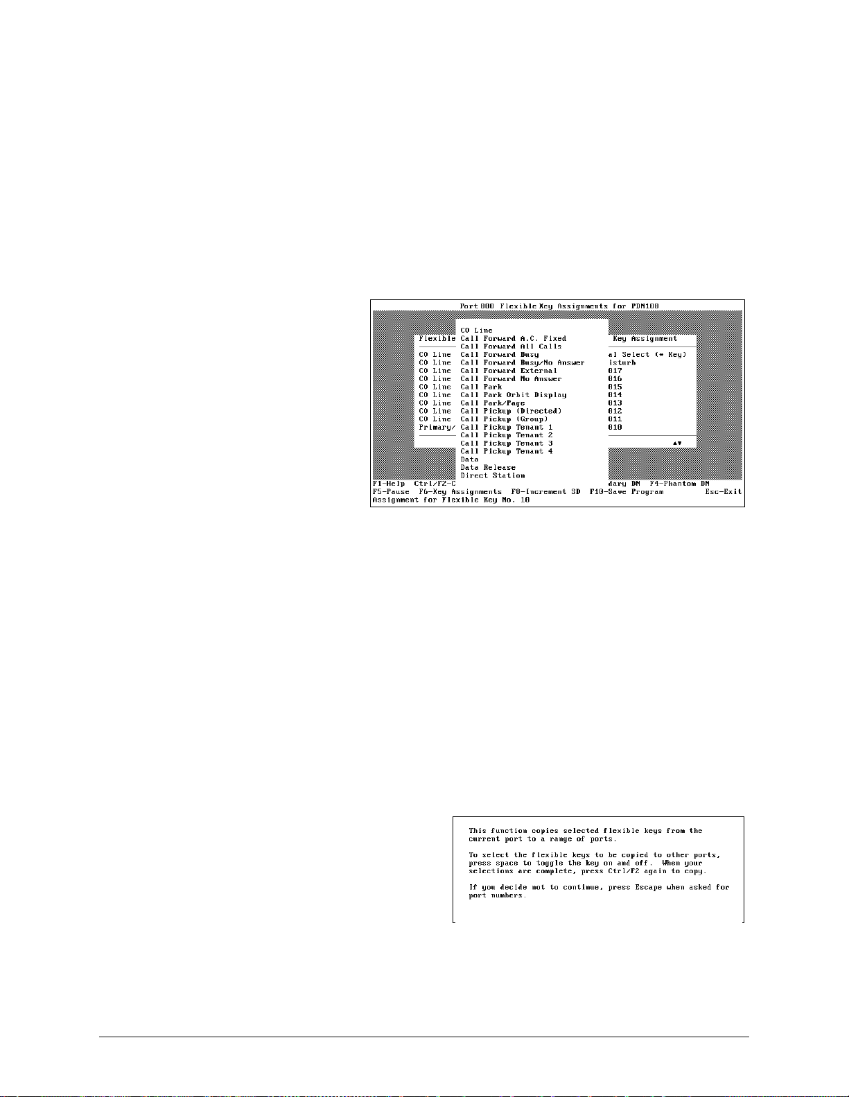
Flexible Button Programming Section –––––––––––––––––––––––––––––––––––––––––––––––––––––––––––––––
3. Press F2 to make the key a Prim ary DN, F3 a Secondary DN, F4 a Phantom DN, or F6 to
change the key feature.
If you press F3 or F4, a pop-up list appears and you must enter a primary or secondary
number. If the number you enter does not exist, the following warning message appears
and you must re-enter the number.
DN Does Not Exist. Please Refer to Program *04.
...or
press F5 to deactivate or blank out a key assignment
...or
if you press F6, a
feature pop-up list
displays (shown right).
Highlight the feature
you want to assign to
the button and press
Enter. Some entries
(such as the CO Line
feature) require you
enter a value when
making an assignment.
The selected feature
replaces the previous
feature.
Note You can only assign a feature to one button within a port. If you attempt to assign a
feature already assigned, an error message displays.
...or
press F8 to add multiple speed dial key assignments.
Important! You can only use this key when you ar e assigning mor e than one speed dial key at
a time. If you have not jus t added a speed dial key a ssignment, the messa ge Must
Assign System/Station Speed Dial First displays.
If you leave the cursor in the same field and continue to press F8, the speed dial
key number incr ements. To add consecutive speed dial key assignments , you must
continue to highlight the next field before pressing F8.
➤ To copy selected keys to selected ports
1. Press Ctrl+F2 and a pop-up dialog
box displays (shown at right).
2. Press any key to continue.
3. Highlight a key and press the spacebar
to select. A asterisk appears next to
your selection. Continue until all the
keys you want to copy have been
selected.
62
DKAdmin/DKBackup
Page 73

–––––––––––––––––––––––––––––––––––––––––––––––––––––––––––––– Flexible Button Programming Section
4. Press Ctrl+F2 again. A pop-up
dialog box displays (shown at right).
5. Type the desired ports and press
Enter. Another pop-up dialog box
displays asking you confirm the
change.
6. Highlight Yes and press Enter to make the change or No to cancel the changes.
7. Press F10 to save the changes you just made.
Add-On Module Button Assignments
➤ To access the option
1. Highlight the Add-On Module Button Assignments option and press Enter.
If you have not yet assigned an add-on module to any of your ports, a message displays:
No Ports Have Add-on Modules. Do You Want To Add A Port?
♦ To add a port, press Enter. A Port Number pop-up box displays: Port Number
000.
♦ Type the port
number for which
you wish to edit addon module button
assignments. The
Add-On Module
Button Assignments
screen displays
(shown right).
This screen enables
you to assign
features (CO Line,
Direct Station,
Station Speed Dial or System Speed Dial) to 20 LED buttons on two add-on modules
(for a total of 40) to any of the physical ports. You can also copy features from one
port to another for quick and easy feature editing.
➤ To make assignments to another port
1. Press F2 and a Port Number pop-up dialog box displays.
2. Type the port number that you wish to work with. If you have not assigned an add-on
module to the specified port, a message displays:
Port does not have add-on module. Add?
3. Press Enter to add an Add-On Module
...or
scroll through t he current Add-On Modules by pressing the + key to display t he next port,
or the - key to display the previous port.
Administration Menu (DKAdmin)
63
Page 74

Flexible Button Programming Section –––––––––––––––––––––––––––––––––––––––––––––––––––––––––––––––
➤ To copy the features from one port to another
1. Highlight the LED you wish to copy and press F4. The Copy to Port dialog box displays.
2. Type the range of port numbers that you wish to copy TO.
3. Highlight the Button Ass ignment Colu mn of Add-On Module 1 or 2 for t he LED you wish
to change and press F3. A message displays at the top of the screen:
Current template copied from port XXX.
Press Enter to display the Feature pop-up box.
4. Highlight the feature you want to assign to the button and press Enter. A value entry
pop-up box displays.
5. Enter the appropriate number or code for the selected feature. The feature is copied from
this port to the ports specified in Step 2.
6. Repeat Steps 1 ~ 5 for each button you wish to copy.
7. Press F10 to save your changes and return to the Flexible Key Program Administration
screen.
➤ To clear the port
1. To clear the port and ret urn to the defau lt settings for all options, press F5. A message
displays: Are you sure?
2. Press Enter to clear the port.
➤ To change an assigned feature
1. Highlight the Button
Assignment column
for either Add-On
Module 1 or 2 for the
LED you wish to
change and press F6.
A feature pop-up list
displays (shown right).
2. Highlight the feature
you want to assign to
the button and press
Enter. A value entry
pop-up displays.
3. Enter the appropriate
number or code for the selected feature.
Note You can onl y as si gn a feature to one butto n per port. If you attempt to assign a feature
already assigned, an error message displays.
64
DKAdmin/DKBackup
Page 75

–––––––––––––––––––––––––––––––––––––––––––––––––––––––––––––– Flexible Button Programming Section
➤ To assign more than one speed dial number
1. Follow the procedure for changing an assigned feature and assign a station/system speed
dial number.
2. Press F8– + SD to add additional speed dial key assignments.
Important! You can only use this key when you ar e assigning mor e than one speed dial key at
a time. If you have not jus t added a speed dial key a ssignment, the messa ge Must
Assign System/Station Speed Dial First displays.
If you leave the cursor in the same field and continue to press F8, the speed dial
key number incr ements. To add consecutive speed dial key assignments , you must
continue to highlight the next field before pressing F8.
DSS Console Button Assignments
➤ To access the option
➤ Highlight the DSS
Console Button
Assignments option
and press Enter. The
DSS Console Button
Assignments screen
displays (shown right)
which enables you to
assign features to 20
DSS console key
buttons.
➤ T o reset all keys and return them
to their defa ult settings
1. Press F5. A message di splays : Are you su re you want to reset flexible
keys?
2. Highlight Yes and press Enter to reset the keys or press Enter to terminate the
resetting.
➤ To change an assigned feature
1. Highlight the key
assignment you wish to
change and press F6. A
feature pop-up list
displays (shown right).
2. Highlight the feature you
want to ass ign to the
button and press Enter.
Some entries (such as the
CO Line feature) require
you type a value when
making an assignment.
Administration Menu (DKAdmin)
65
Page 76

Flexible Button Programming Section –––––––––––––––––––––––––––––––––––––––––––––––––––––––––––––––
The selected feature replaces the previous feature.
Notes
● You can only assign a feature to one button within a console. If you attempt to assign a
feature already assigned, an error message displays.
● Press F8–Increment SD to add additional speed dial key assignments.
Important! You can only use this key when you ar e assigning mor e than one speed dial key at
a time. If you have not jus t added a speed dial key a ssignment, the messa ge Must
Assign System/Station Speed Dial First displays.
If you leave the cursor in the same field and continue to press F8, the speed dial
key number incr ements. To add consecutive speed dial key assignments , you must
continue to highlight the next field before pressing F8.
3. After setting each key, press F10 to save your changes and return to the Flexible Key
Program Administration screen.
➤ To make assignments to another console or console group
1. Scroll to another console/console group (+ scrolls forward, - scrolls backward).
2. Press Esc to clo se the DSS Console Button Assign ments scre en and r eturn to th e Flexi ble
Key Program Administration screen.
Attendant Console Flexible Button Assignments
Note This option cannot be used by Strata DK Release 2 or below.
➤ To access the option
➤ Highlight the Attendant
Console Flexible Button
Assignments option and
press Enter. The
Attendant Console
Flexible Button
Assignments screen
displays (shown right).
This screen enables you
to assign feat ures to both
left and right key
assignments.
66
DKAdmin/DKBackup
Page 77

–––––––––––––––––––––––––––––––––––––––––––––––––––––––––––––– Flexible Button Programming Section
➤ To edit your attendant console flexible button assignments
1. Highlight the key
assignment you wish
to change and press
F6. A feature pop-up
list displays (shown
right).
2. Use the +/- keys or
the Page Up/Page
Down keys to scroll
through the list.
Highlight the feature
you want to assign to
the key and press
Enter. The selected feature replaces the previous feature.
3. To move between the left and right key assignments, press F2.
♦ You can only assign a feature t o one butto n withi n a console . If you a ttempt to assign a
feature already assigned, an error message displays.
♦ Press F8–+ SD to add additional speed dial key assignments.
Important! You can only use this key when you ar e assigning mor e than one speed dial key at
a time. If you have not jus t added a speed dial key a ssignment, the messa ge Must
Assign System/Station Speed Dial First displays.
If you leave the cursor in the same field and continue to press F8, the speed dial
key number incr ements. To add consecutive speed dial key assignments , you must
continue to highlight the next field before pressing F8.
4. After setting each key, press F10 to save your changes and return to the Flexible Key
Program Administration screen.
➤ To reset all keys and return them to their default settings
1. Press F5. A message displays:
Are you sure you want to reset flexible keys?
2. Press Enter to reset the keys.
➤ To make assignments to another attendant console
1. Scroll to another attendant console (+ scrolls forward, - scrolls backward).
2. Press Esc to close the Attendant Console Flexible Button Assignments screen and return
to the Flexible Key Program Administration screen.
Administration Menu (DKAdmin)
67
Page 78

Speed Dial Programming Section ––––––––––––––––––––––––––––––––––––––––––––––––––––––––––––––––––
Speed Dial Programming Section
The Speed Dial Programming Section option in the Administration Menu enables you to
maintain system and station speed dial assignments.
➤ To access speed dial assignments
➤ Type d; the System &
Station Speed Dial
Administration screen
displays (shown right).
System Speed Dial Numbers
➤ T o edit sys tem speed dial number
assignments
1. Press Enter. The
System Speed Dial
Numbers screen
displays (shown right ).
This screen enables
you to assign or edit up
to 800 syst em speed
dial numbers for the
RCTUE/F processor,
100 for RCTUBA/BB,
RCTUC/D processors,
and 40 for TMAU and
RCTUA processors.
68
2. Highlight the System
Speed Dial No. field and type the speed dial telephone number, including area code, and
press Enter.
3. Highlight the System Speed Dial Memo field and enter a description of the speed dial
number (up to 12 characters). This memo displays on the telephones LCD when the Bin
Number is selected by an LCD telephone using the MODE 8XXX function (where XXX
is the speed dial bin number).
4. Press F9 to save the entries and upload the data to the DK or F10 to save the speed dial
assignments and return to the System/Station Administration screen.
DKAdmin/DKBackup
Page 79

––––––––––––––––––––––––––––––––––––––––––––––––––––––––––––––––– Speed Dial Programming Section
Station Speed Dial Numbers
➤ To edit station speed dial number assignments
1. Highlight the Station
Speed Dial Numbers
option and press
Enter. The Station
Speed Dial Numbers
screen displays (sho wn
right).
Note T o make ent ries or
edit the Telephone
Location, Log.
Port No., Int/DN
No. and T elephone
LCD User Name fields, you must access the System/Station Administration screen
under the System/Station Administration option.
2. Highlight the Physical
Port No. field and
press F7. The Port
Speed Dial Numbers
& Memos screen
displays (shown right).
3. Highlight the Speed
Dial Number field for
the appropriate Speed
Dial Bin Number.
Type the telephone
number (including area
code) and press
Enter.
4. Highlight the Speed Dial Memo field and enter a description of the speed dial number
(using up to 12 characte rs). This memo displays on the telephones LCD when the Bin
Number is selected by an LCD telephone using the MODE 8XXX function (where XXX
is the speed dial bin number).
5. Press F9 to save the entries and upload the data to the DK
...or
press F10 to save the speed dial assignments and return to the System & Station Speed
Dial Administration screen
...or
press Esc to return to the previous menu without saving. A pop-up box appears: Data
modified. Save modified data?
Press Enter to save or N to return to the previous screen without saving.
Administration Menu (DKAdmin)
69
Page 80

ACD Administration –––––––––––––––––––––––––––––––––––––––––––––––––––––––––––––––––––––––––––––
CAUTION! The DKAdmin PC must be connected to the Strata DK to upload any
changes to this data (see Appendix A – Connecting to Strata DK for
procedures on connecting the DKAdmin PC to a Strata DK).
6. Press Esc to close the System & Station Speed Dial Administration screen and return to
the Main Menu.
ACD Administration
The ACD Administration Section option in the Administration Menu enables you to maintain
your ACD and ACD Agent programs.
➤ To access ACD administration
➤ Type a. The DK Program
File Selection screen
displays (shown right).
ACD Programs
➤ To edit ACD programs
1. Press Enter; the ACD
Programs screen displays
(shown right). This
screen enables you to
edit ACD programs (you
can edit any program
with a check mark next
to it).
70
DKAdmin/DKBackup
Page 81

–––––––––––––––––––––––––––––––––––––––––––––––––––––––––––––––––––––––––––– ACD Administration
2. Highlight the program
number and press F3.
The Edit Program
screen displays (sho wn
right). The screen
varies, depending upo n
the program selected.
Note You can also use
the Find function
to quickly move to
a program by
typing the first
digit of the program number. DKAdmin highlig hts the fir st progra m number matching
the entry.
3. Highlight the field you wish to change and enter the information. Read only fields do not
accept entries.
4. Press F9 to save the entries and upload the data to the DK, or F10 to save the speed dial
assignments and return to the ACD Programs screen.
Important! The DKAdmin PC must be connected to the Strata DK to upload any changes to
this data (see Appendix A – Connecting to Strata DK for procedures on
connecting the DKAdmin PC to a Strata DK).
5. Press the Esc key to close the ACD Programs screen and return to the DK Program File
Selection screen.
➤ To view notes on a program
➤ Highlight the program and press F5.
Note You can also use the Find function to move quickly to a program by typing the first
one or two digits of the program number. The program highlights the first program
number matching your entry.
♦ Use the Up/Down arrow keys to scroll the description.
♦ Press F10 to print the description.
♦ Press Esc to return to the ACD Programs screen.
➤ To use the Strata DK’s program files to edit
1. Press F2 and the DK Code dialog box displays.
2. Type the DK Code: XXXX, where XXXX is the DK level 1 security code set in Program
00. The DK System Program File screen displays.
Note If the Problem: Unable to Establish Communications screen
displays, follow the troubleshooting steps on the screen and/or refer to Appendix A –
Connecting to Strata DK to correct the problem.
3. Press F2 to select (tag) all Program No. (data) files.
4. Highlight Yes and press Enter . DKAdmin establ ishes c ommunicatio ns to t he Stra ta DK,
turns on LED 10 in Program 77-1, and receives data blocks. This information displays on
the PC screen as it occurs.
Administration Menu (DKAdmin)
71
Page 82

ACD Administration –––––––––––––––––––––––––––––––––––––––––––––––––––––––––––––––––––––––––––––
5. Follow Step 2 ~ Step 4 of “To edit ACD programs” on Page 70.
ACD Agent Programs
➤ To edit ACD agent programs
1. Highlight the ACD
Agent Programs optio n
and press Enter. The
ACD Agent Programs
screen displays (sho wn
right). This screen
enables you to edit
ACD Agent programs.
2. Highlight the ACD
Group Number field
for the ACD Agent
you wish to change. Type the new two-digit Group number (01 ~ 08) and press Enter.
3. Highlight the ACD Agent ID Code field and enter a four-digit ACD Agent ID Code
Number (0000 ~ 9999). If you type less than four digits, the program zero fills the field.
Press Enter.
4. Highlight the ACD Agent Name field. Type the Agent’s na me ( up to eight characters) and
press Enter .
5. Highlight the Auto Answer Assignment. Use the spacebar or +/- keys to toggle between
Auto Answer and No Auto Answer.
6. Press F9 to save the entr ies and uploa d the data to th e DK, or F10 to save the speed dial
assignments and return to the ACD Programs screen.
Important! The DKAdmin PC must be connected to the Strata DK to upload any changes to
this data (see Appendix A – Connecting to Strata DK for procedures on
connecting the DKAdmin PC to a Strata DK).
7. Press Esc to clo se th e ACD Prog rams s creen and return t o the DK Progr am File Sele ction
screen.
72
DKAdmin/DKBackup
Page 83

––––––––––––––––––––––––––––––––––––––––––––––––––––––––––––––––––– Program Administration Section
Program Administration Section
The Program Administration Section option in the Administration Menu enables you to
maintain Strata DK programs. This includes pulling the program from the DK, editing the
program, initializing the Strata DK processor, or sending the program to the Strata DK.
For complete information on Strata DK programs, including default definitions, refer to the
Strata DK Programming Manual.
➤ To access a Strata DK program
1. Type p and the DK
Program File Selection
screen displays (sho wn
right).
2. Highlight the option
on the screen y ou wish
to select and press
Enter. The selected
screen displays. See
Table 4 for a list of
available programs.
Table 4 Available Programs
Program Title Program Title
View All Programs (Download, Edit, Upload) Toll Restriction Programs
View System Features by Subject Data Interface Unit Programs
System Number Plan & Port Locations Doorphone/Ext. Paging/BGM/Conference
System Wide Option Programs LCR Programs
Station Options Programs Multiple Directory Number Programs
Station (Gnd/Loop) CO Line Assignment Programs ANI Programs
Station Group Programs DNIS Programs
Security/Account/T.R. Ovr. Programs DKT/RPCI/OA Interface Programs
Voice Mail Integration Programs Class/Caller ID Programs
ACD Programs Distributed Hunt Programs
ACD Agent Programs Call Park Programs
DK Auto Attendant Programs Off Hook Call Announce Programs
Attendant Console Programs Standard Telephone MW/Camp-on Tone Programs
T1 Programs Enhanced 911/CAMA Trunk Programs
Ground/Loop Start CO Line Programs ISDN Programs
DID/TIE Line Programs Initialization Programs
IMDU or RMDS Modem/DID/DNIS Assignment
Administration Menu (DKAdmin)
73
Page 84

Program Administration Section –––––––––––––––––––––––––––––––––––––––––––––––––––––––––––––––––––
After selecting the program, you have the following options:
♦ Press F2 to pull the program data from the DK. See “Res to re Da ta ” on Page 102 for
procedures on downloading data.
♦ Press F3 to edit the program. Only programs displaying a check mark may be edited
by your password level. Options fo r editing pr ograms dif fer dependi ng on the select ed
program. They may include:
F2 - Reset Ports Resets the ports to their original configuration.
F2 - Range Enter a range to apply a change.
F9 - Save & Upload Save the change and upload the data to the DK.
F10 - Save Save the change in DKAdmin customer database and
return to the originally selected program screen.
F10 - Initia lize Initialize the Strata DK processor with selected
Program 90, 91, or 92; this does not affect DKAdmin
customer data files.
♦ Press F5 to view notes on the program.
♦ Press Esc to return to the DK Program File Selection screen. Press Esc again to
return to the D KAdmin Main Menu.
View All Programs (Download, Edit, Upload)
➤ To access the option
1. From the DK Program
File Selection screen,
press Enter and the
View All Programs
(Download, Edit,
Upload) screen
displays (shown right).
2. Highlight the desired
program.
Note To find a program
number quickly,
type the number and t he displa y scr een “j umps” t o the progra m number. If the number
you have typed does not exist, a dialog box displays telling you the number was not
found.
➤ To pull the program data from the DK
➤ Press F2 to pull the program data from the DK. See “Restore Data ” on Page 102 for
procedures on downloading data.
74
DKAdmin/DKBackup
Page 85

––––––––––––––––––––––––––––––––––––––––––––––––––––––––––––––––––– Program Administration Section
➤ To edit a program
1. Press F3 and the
Directory Numbers
Assignments screen
displays (shown right).
2. Highlight the logical
port number and press
F2 to reset the DN for
the logical port
numbers on a range of
ports.
3. A change dialog box
displays and you must
enter the starting DN. A pop-up screen displays asking you to confirm the change:
This operation will modify DN numbers. Go ahead?
4. Press Enter to change the port numbers.
5. Press F9 to save the entries and upload the data to the DK, or F10 to save the changes in
the DKAdmin customer database and return to the DK Program File Selection screen.
➤ To print progr ams
1. Press F4 and a printer pop-up dialog box displays. The default printer is checkmarked.
2. Press Enter to print or highlight another printer and press F2 to select.
3. If a printer is not d esignate d for the sel ected por t, press F2 again and a printer list displays.
Highlight the appropriate printer and press Enter.
➤ To view notes on a program
➤ Highlight the program and press F5.
Note You can also use the Find function to move quickly to a program by typing the first
one or two digits of the program number. The program highlights the first program
number matching your entry.
The following keys can be used when viewing program notes:
♦ Use the Up/Down arrow keys to scroll the description.
♦ Press F10 to print the description.
♦ Press Esc to return to the ACD Programs screen.
Administration Menu (DKAdmin)
75
Page 86

Program Administration Section –––––––––––––––––––––––––––––––––––––––––––––––––––––––––––––––––––
When using DKAdmin, Table 5 pro vides important information regarding specific
programs:
Table 5 DKAdmin Program List
Program Comment
Program 03 On new or upgraded insta llatio ns, Program 03 sh ould a lways be ch ecked and
Program 04 or
Program *09 and 76-0 DKAdmin edits and uploads Programs *09 and 76-0 in the same manner as
PRGALL Whenever PRGALL is uploaded (restored), Programs 04 and
Program 38/39 To change a keystrip from 20 to 10 keys, or from 10 to 20, without changing
04 When editing Directory or DN/intercom numbers in Programs 04 or
*
uploaded to make sure all PCB slots have the correct codes for PCBs and
PCB options. Strata DK power must be turned off (5-seconds) and then on
after uploading (restoring) Program 03 to enable its data to take effect.
04,
*
09 are
*
DKAdmin checks for duplicate or conflicting numbers and stops them from
being entered. When uploading Programs 04 or
them from the processor, compares and arranges the data in an acceptable
order and uploads it to the Strata DK.
Programs 04 and
04.
*
CAUTION! ACD/DID assignments in Program
(uploaded) with early ROM versions of Strata DK Release 2
ROMs.
downloaded and checked, then uploaded prior to the PRGALL upload.
the data in Program 39, select and edit Program 38 using Program
Administration. To change a keystrip to a default value in Program 38 and
overwrite Program 39 data, select and edit TELEPHONE KEYSTRIP TYPE
(PRG38) from the System/ Station Adminis tration-POR T A TTRIBUTES s creen
for the selected station port. When changing a keystrip from 20 keys to 10
keys, DKAdmin store s t he pause (code 495) key i n k ey 11~20 (unused keys).
This is because there is no code for a blank key.
If using Strata DK Release 2 or lower, you must power off (5 sec)/on the
Strata DK after sending the changes to the Strata DK from DKAdmin in order
for the program changes to take effect.
04, DKAdmin downloads
*
09 cannot be Restored
*
Program 90, 91, and 92 All Initialization programs will initialize the data in the Strata DK processor
REPALL These two files will always be Up or Down loaded in pairs when either file is
Program 04, *04, *09, and
76-0
76
(RCTU PCB), not the data in the DKAdmin PC customer files.
If initializing the system with 91-9 remotely, the customer DK TTY port must
be connected to a mo dem that has a direct CO li ne as shown in Figure A-3 of
Appendix A.
Up or Down loaded.
Unused ports in these programs will be blanked out when upgrading to an
RCTU with more port number than the ori gin al RCT U. Th is is d one to pre ve nt
inserting DN and DID number conflicts during an upgrade. For example, if
upgrading from a RCT UB to and RCT U C/D, po rts 80~ 239 will be blank ed out
in Program 04.
DKAdmin/DKBackup
Page 87

–––––––––––––––––––––––––––––––––––––––––––––––––––––––––––––––––––– Security Maintenance Section
Security Maintenance Section
The Security Maintenance Section option (level 9 password required to access this option)
enables you to set up to three levels of security using:
♦ Passwords - defines the functions available to users using menu-specific passwords as
described on Page 121.
♦ Program Access - defines the programs which can be used by each password level using
the Security Maintenance Section option (see “Program Security (Default Levels)” on
Page 78).
♦ DK Access Code - must be entered to enable a user to send and/or receive data to/from a
Strata DK. The default for this code is 0000 and may be changed (but not viewed) by
DKAdmin users that have an allowable password level.
➤ To limit the Strata DK programs a user may edit
1. From the
Administration Menu,
type u to display the
DK Program Security
Maintenance screen
(shown right).
The screen lists the
Strata DK programs
available for
programming or
updating. You can
limit programs a user
can access by
assigning a security
level (which corresponds to the users assigned password level).
Note Program access security limits direct access of programs when using the Program
Administration Section Option. When using the ACD Admin is tr at ion Sec ti on Opti on,
only Programs 01, 02, 04,
denied from the normal System/Station Administration functions.
09, VMID, MWID, and Perso nal Sp eed Di al acce ss can be
*
2. Highlight the S/L field of the desired program. Type the password level (0 ~ 9,
9=highest) you want to assign for accessing the program and press Enter.
Note For a complete list of Passwo rd/Program default levels, s ee “Program Security
(Default Lev els)” on Page 78.
...or
to assign all the pr ograms to a particular pas swor d level, press F2-r eset. A Security Level
dialog box displays. Type the password l eve l ( 0 ~ 9, 9=highest) you want to as si gn t o a ll
the Strata DK programs and press Enter. A confirmation message displays. Highlight
Yes and press Enter .
The Security Level for all programs are changed to the entered password level.
3. To close the DK Program Security Maintenance screen, press Esc.
Administration Menu (DKAdmin)
77
Page 88

Security Maintenance Section –––––––––––––––––––––––––––––––––––––––––––––––––––––––––––––––––––––
Note The password levels (0 ~ 9) are based on a hierarchal system. This means that
password level 9 has access to all programs, but password level 5 (for example) has
access to all programs tagged with 5 and below, but not 6 and above.
Program Security (Default Levels)
Program security is mainta ined by assi gning access lev els to each pr ogram. The acces s level is
assigned to each User ID/Password so each User ID/Password can be allowed or denied edit/
view privileges to selected Strata DK programs. DKAdmin provides default levels for User
IDs/Passwords and program security (listed below). These passwords and program security
levels may be added or changed by logging onto DKAdmin with a level 9 (Master) password.
The default User ID/Password and Program Security levels are shown below:
User ID Password Program Security Level
ADMIN1 ADMIN1 2
ADMIN2 ADMIN2 5
TECH1 TECH1 8
MASTER MASTER 9
Table 6 Strata DK Program Security
Strata DK
Program
REPALL 2 All Station and System Speed Dial Numbers
NAMEALL 2 All User Names
VIDALL 3 All Voice Mail ID Codes (#656)
MIDALL 3 All Voice Mail Message Waiting Codes (#657)
ADMEMOALL 2 All Station and System Speed Dial Memos
MSGALL 2 All Station and System LCD Messages
CFALL 2 All Call Forward Settings
MWALL 2 All Message Waiting Settings
CLID 2 All Class/ANI Lost Call Number Storage Data
*03 0 Cabinet Compatibility (DK424)
04 0 Directory Numbers Assignment (R3)
*
05 0 Call Park Pickup Access Codes (R3)
*
09 8 DID Digit Translation
*
10 8 E911 Assignments (R3.1)
*
*11-0 0 CAMA Trunk Assignments (R4)
*11-1 0 CAMA Trunk Group Line Assignments (R4)
Security Level Program Title
78
*11-2 0 CAMA Trunk Gro up Hunting Assignments (R4)
*11-5 0 CAMA Digit Sent on 911 Calls (R4)
*11-6 0 E911 Interdigital Timer (R4)
DKAdmin/DKBackup
Page 89

–––––––––––––––––––––––––––––––––––––––––––––––––––––––––––––––––––– Security Maintenance Section
Table 6 Strata DK Program Security
Strata DK
Program
*11-8 0 911 Special [DN] Notification Assignments (R4)
*12 0 ANI Station Information (R4)
*13 0 Station Group Information (R4)
14-1 5 Auto Answer with Zip Tone Assigned to Agent ID
*
14-2 5 DID/TIE Line After Shift & Overflow Substitution Destination
*
15 8 CO Line Tenant Assignments
*
*16 8 ISDN Trunk Group Type Assignments (R4)
17 8 DID Intercept Port Number (Caller Dials Vacant/Wrong Number)
*
29 5 Add-On Module Button Assignments
*
30 5 Group Page Assignments
*
31 5 Group Pickup Assignments
*
32 8 Voice Mail Message Center Port (RS-232)
*
33 8 Phantom D N Own er Assi gn men ts (R3)
*
34 8 Station Class of Service
*
36 8 Night Transfer Lock Button “Password Change” Station (R3)
*
37 8 Station Park Recall Timer (R3)
*
40 8 Station Distributed Hunt Group Assignments (R3.1)
*
41-1 8 T1 Span Frame and Coding Assignments
*
41-2 8 T1 Channel Assignments
*
41-3 8 T1 Span Transmit (Send) Level PAD Assignments
*
41-4 8 T1 Span Receive Level PAD Assignments
*
42-1~2 8 Primary & Secondary Clock Source Reference Assignments
*
*43-1~3 8 ‘D’ Channel Control and NFAS Assignment (R4)
Security Level Program Title
(continued)
*44 8 BRI SPID Parameters (R4)
45-1 8 Office Code Toll Restriction (R3.0)
*
45-2 8 Special Numbers that Do Not begin with */# (R3.0)
*
45-3 8 Special Numbers that begin with */# (R3.0/R3.1)
*
50 8 RCIU/RCIS Port Assignment
*
51 8 Station Caller ID/ANI Lost Call Memory Allocation (R3)
*
52 8 Common CO Line Caller ID Lost Call Owner (R3)
*
*60 0 BRI Assignment for Line/Station Operation (R4)
*61-1 0 ISDN Station Bearer Service (R4)
*61-2 0 ISDN Station Outgoing Call Pad Level (R4)
*61-3 0 ISDN Station Incoming Call Pad Level (R4)
*62-1 0 Non-ISDN Station Bearer Service (R4)
Administration Menu (DKAdmin)
79
Page 90

Security Maintenance Section –––––––––––––––––––––––––––––––––––––––––––––––––––––––––––––––––––––
Table 6 Strata DK Program Security
Strata DK
Program
*62-2 0 Non-ISDN Station Outgoing Call Pad Level (R4)
*62-3 0 Non-ISDN Station Incoming Call Pad Level (R4)
*63 0 ISDN Dialing Parameters (R4)
*64-1 0 Direct Inward Dialing Parameters (R4)
*64-2 0 Direct Inward Dialing Parameters (R4)
*65 0 ISDN Channel Group Assignment (R4)
*66-1 0 Channel Parameters (R4)
*66-2 0 Call-by-Call Trunk Group Codes (R4)
*66-3 0 Channel Group Parameters (R4)
*66-4 0 Call-by-Call Network ID (R4)
*66-5 0 Line Directory Number (LDN) Registration (R4)
*66-6 0 Line Directory Number (LDN) Channel Groups (R4)
*66-7 0 Line Directory Number (LDN) Trunk Groups (R4)
*67-1 0 Trunk Group Parameters (R4)
*67-2 0 Call Types for ISDN Trunk Group Supported (R4)
*67-3 0 Call Types for ISDN Trunk Groups (R4)
Security Level Program Title
(continued)
*67-4 0 Call Types for ISDN Trunk Groups (R4
*68-1 0 Calling Number ID Presentation Parameters (R4)
*68-2 0 Outbound Calling Number ID Presentation Parameters (R4)
*69-1 0 CNIS Presentation Parameters (R4)
*69-2 0 Special Number Assignment (R4)
71 8 Ringing DN Assignment for Immediate Ring (R3)
*
72 8 Ringing DN Assignment for Delay 1 Ring (R3)
*
73 8 Ringing DN Assignment for Delay 2 Ring (R3)
*
79 8 Doorphone Ring LED Assignments (R3)
*
*80 0 Call Forward Ringing Assignments (R3.2)
81 8 DN LED Display Assignment (DAY Mode) (R3)
*
84 8 DN LED Display Assignment (DAY2 Mode) (R3)
*
87 8 DN LED Display Assignment (NIGHT Mode) (R3)
*
00 8 Software Check/Remote Password Assignments
01 8 Logical Station Ports
02 8 Physical Station Ports
03 8 Flexible PCB Cabinet and Slot Assignments
04 8 Logical Port Intercom Number Assignments
80
05 8 Flexible Access Code Numbering
DKAdmin/DKBackup
Page 91

–––––––––––––––––––––––––––––––––––––––––––––––––––––––––––––––––––– Security Maintenance Section
Table 6 Strata DK Program Security
Strata DK
Program
09 8 Auto Attendant Prompt/Station Assignments
10-1 8 System Assignments
10-2 8 System Assignments
10-3 8 System Assignments
10-4 5 ACD Parameters
11 5 ACD Timing Assignments
12 8 System Assignments - Basic Timing
13 8 Defining the Message Center
14-0 5 ACD CO Line Assignments
14-1 5 ACD Agent Identification Code Assignments
14-2 5 ACD Supervisor Passwords
14-3 5 Announcement/Music Port Assignments
14-4 5 Overall Queue Time Out Destination
14-5 5 Overflow Operation/Destination Assignments
14-6 5 End of Shift Service Destination
14-71 5 Queue Size for Alarm (Immediate)
Security Level Program Title
(continued)
14-72 5 Queue Size for Alarm 1 (Timed)
14-73 5 Queue Time for Alarm 2 (Timed)
14-8 5 Alarm Pattern Assignments
14-9 5 Stroke Count Assignments
15 8 Assigning DP/DTMF, Tenant Service To Individual CO Line
16 8 Assign CO Line Groups (Dial 9 or 001~816)
17 8 DID/TIE Line Options
18 5 Agent ID Code Name for MIS Assignments
19 8 Alternate Background Music (BGM) Slot Identification
20 8 DIgital Data Port Configuration
21 8 Modem Pool Port Assignments
22 8 Data Interface Unit (DIU) Station Hunting (Data Calls Only)
23 8 Primary Auto Attendant Announcement Device Assignments
24 8 Secondary Auto Attendant Announcement Device Assignments
25-1 8 Incoming Auto Attendant Call Overflow Time
26 5 Built-In Auto Attendant Camp-On Busy Time
27 5 Digital Telephone Handset Receiver Volume Level
28 8 DSS Console/Attendant Telephone Assignments
29 5 DSS Console Button Assignments
Administration Menu (DKAdmin)
81
Page 92

Security Maintenance Section –––––––––––––––––––––––––––––––––––––––––––––––––––––––––––––––––––––
Table 6 Strata DK Program Security
Strata DK
Program
30 5 Station Class of Service
31 5 Station Class of Service
32 5 Automatic Preference
33 5 Station Hunting (Voice Calls Only)
34 5 Hold/Park Recall Timing
35 5 Station Class of Service
36 5 Fixed Call Forward (Voice Calls Onl y )
37 5 CO and TIE Line Ring Transfer (Camp-on) Recall Time
38 5 Digital and Electronic Telephone Keystrip Type
39 5 Flexible Key Assignment Button Codes
40 5 Station CO Line Access
41 5 Station Outgoing Call Restriction
42-0 8 CO Line to PBX/Centrex Connection
42-1~8 8 PBX/Centrex Access Code
43 5 Station/CO Line Credit Card Call Allowed
44-1~8 5 Toll Restriction Class Traveling Class Override Code
Security Level Program Title
(continued)
44-91~93 5 Emergency Bypass of Forced, Verified Account Codes
45-1 8 LCR/Toll Restr iction Dial Plan
45-2 5 Toll Restriction Disable
45-3~6 8 Special Common Carrier (SPCC) and Auth. Code Digital Length
45-8~9 8 Toll Restriction Override Code
46-10~80 8 Toll Restriction Class Parameters
46-11~81 8 Toll Restriction Class Parameters
46-2~4 8 Toll Restriction Allowed/Denied Area Codes by Class
46-6~8 8 Toll Restriction Allowed/Denied Office Codes by Class
47 8 Toll Restriction Exception Office Codes by Area Code
48 5 Station Toll Restriction Classification
50-1 8 LCR Parameters
50-2 8 LCR Home Area Code
50-31~35 8 LCR Special Code
50-4 8 LCR Long Distance Information (LDI) Plan Number
50-5 8 LCR Local Plan Number
50-6 8 LCR Dial Zero Timeout
51 8 LCR Area Codes
82
52 8 LCR Office Code Exceptions for Specified Area Codes
DKAdmin/DKBackup
Page 93

–––––––––––––––––––––––––––––––––––––––––––––––––––––––––––––––––––– Security Maintenance Section
Table 6 Strata DK Program Security
Strata DK
Program
53 8 LCR Schedule Assignments for LCR Plans
54 8 LCR Route Definition Tables
55-0~2 8 LCR Modified Digits Tables
56 5 LCR Station Group Assignments
58-1 5 Attendant Console Overflow Timer
58-2 5 Attendant Console Display Type
58-4 5 Attendant Console Answer Key Priority Assignments
58-5 5 Attendant Console Overflow Destination Assignments
59 5 Attendant Console Flexible Button Codes
60-1 8 SMDR Printout data of CLASS/ANI/DNIS or Account Code
60-2~7 5 SMDR Output/Account Code Digit-Length
60-8 5 Call Forward External (Remote Change, Security) ID Code
69 5 Verified Account Codes
70 5 Verified Account Code Toll Restriction Assignments
70-0 8 DNIS Number Assignments (R3)
71-0 0 DNIS Number Assignments
Security Level Program Title
(continued)
71-1 8 DNIS Ringing Point Assignments (DAY Mode) (R3)
71-2 8 DNIS Ringing Point Assignments (DAY2 Mode) (R3)
71-3 8 DNIS Ringing Point Assignments (NIGHT Mode) (R3)
71-4 8 DNIS Voice Mail ID Assignments (R3)
71-5 8 DNIS Name Tag Assignments (R3)
72 8 DNIS Network Table (R3)
74 8 Night Transfer Lock Button Password(s) (R3)
76-1~2 8 Interface Port Type & Transmission Speed (R3)
77-1 8 Peripheral Options (Door Phones/IMDU/PIOU/PIOUS/PEPU/RM
77-2 8 Door Phone Busy Signal/Door Lock Assignments
77-3 8 Night Ringing Over Tenant External Page Zones
77-4 8 Open Architecture Interface Attributes (R3.2)
78 5 CO Line Special Ringing Assignments: DSS/IMDU, Night Ringing
79 5 Door Phone Ringing
80 5 Digital & Electronic Telephone Ringing Tones (CO Line Calls)
81 5 CO Line/Station Ringing Assignments (DAY Immediate)
82 5 CO Line/Station Ringing Assignments (DAY 12-Second De lay)
83 5 CO/Line/Stat ion Ringing Assignments (DAY 24-Second Delay)
84 5 CO/Line/Stat ion Ringing Assignments (DAY 2 Immediate )
Administration Menu (DKAdmin)
83
Page 94

Security Maintenance Section –––––––––––––––––––––––––––––––––––––––––––––––––––––––––––––––––––––
Table 6 Strata DK Program Security
Strata DK
Program
85 5 CO/Line/Station Ringing Assignments (DAY 2 12-Second Delay)
86 5 CO/Line/Station Ringing Assignments (DAY 2 24-Second Delay)
87 5 CO/Line/Station Ringing Assignments (NIGHT Immediate)
88 5 CO/Line/Station Ringing Assignments (NIGHT 12-Second Delay)
89 5 CO/Line/Station Ringing Assignments (NIGHT 24-Second Delay)
90 8 Initializing Program 00~
91-1 8 Automatic PCB Recognition/Port Renumber
91-2 8 System Power Off/On Simulation
91-9 8 System Initialization
92-1 8 Initialize Station Speed Dial Numbers & Memos, VM ID Codes
92-2 8 Initialize System Speed Dial Numbers & Memos
92-3 8 Initialize Station & System User Name/Number Display
92-4 8 Initialize Timed Reminders
92-5 8 Initialize Phone/Ring Vol., Tone/BGM, Busy Override, etc.
92-9 8 Initialize Call Forward Memory
93 5 CO Line Identification
Security Level Program Title
(continued)
99
*
97 5 Printing Program Through SMDR
84
DKAdmin/DKBackup
Page 95

–––––––––––––––––––––––––––––––––––––––––––––––––––––––––––––––––– Directory Number Administration
Directory Number Administration
Note This option cannot be used by Strata DK Release 2 or below.
➤ To maintain your directory number assignments for both your PDNs and PhDNs
1. Press r and the
Directory Number
Administration screen
displays (shown right).
This screen enables you
to assign and change
PDN and PhDN user
names, call fo rward ID
codes and message
waiting ID codes. You
can also assign or edit
DNIS detail features
such as immediate ring,
key numbers and delays.
Note The first column on the screen displays a P for a PDN and an F for PhDN.
2. Highlight the PDN/PhDN No. field of the desired port number.
Note You can also use the Find feature by moving the highlighter to the Port No. field, and
typing a port number.
3. T ype a [PDN] or [PhDN], and pres s Enter. If the re is a DN/Por t conf lict with the e ntere d
number, an error message displays: Conflict Found in Int./DN Numbering
If this message appears, retype the number and press Enter
...or
to change the PDN/PhDN numbers for a range of ports, hi ghlight the PDN/P hDN No. field
and press F5. A pop-up box displays.
♦ Type the desired starting [DN] number for your PDN ports (000-079) and press
Enter.
♦ Type the desired starting [DN] number for your PhDN ports (500-579) and press
Enter.
♦ A message displays: This operation will modify DN numbers. Go
ahead?
Press Enter to change all the PDNs/PhDNs or press Esc to leave the screen without
making the change.
4. Highlight the PDN/PhDN Owner User Name field and enter the name assigned to the
station (up to 16 characters).
5. Highlight the Voice Mail Call Forward ID Code field and type an applicable call forward
ID code (up to 16 characters). Press Enter
...or
Administration Menu (DKAdmin)
85
Page 96

Directory Number Administration –––––––––––––––––––––––––––––––––––––––––––––––––––––––––––––––––––
to change the range of numbers used for all the ports, press F5. A pop-up box displays,
enabling you to specify a range of numbers.
♦ Type the desired range of Port Reference Numbers for the PDNs (000 ~ 079).
♦ Type the desired range of Port Reference Numbers for the PhDNs (500 ~ 579).
♦ Type a Voice Mail CF Prefix (up to four characters) and press Enter. A message
displays: All ports will be reset to default values. Go
ahead?
Press Enter to set/change all Call Forwa rd IDs.
6. Highlight the Voice Mail Me ssage Waiting ID Code f ield and enter an ap plicable message
waiting ID code (up to 16 characters)
...or
to change the range of numbers used for all your ports, press F5. A pop-up box displays,
enabling you to specify a range of numbers.
♦ Type the desired Port Reference Number for the PDNs (000 ~ 079).
♦ Type the desired Port Reference Number for the PhDNs (500-579).
♦ Type a Voice Mail MW Prefix (up to four characters) and press Enter. A message
displays: All ports will be reset to default values. Go
ahead?
Press Enter to set/change all Message Waiting IDs.
7. Press F9 to save the entr ies a nd upl oad the data to t he DK, or F10 to save t he as signmen ts
and return to the Main Me nu.
➤ To set or change detailed information for the PDNs/PhDNs
1. From the Directory Number Administrati on scree n, highli ght the DN you wish to edi t and
press F2. The Directory Number Administration screen for the selected DN number
displays.
This screen (shown
right) enables you to
turn on or off an
immediate ring, or a
12- or 24-seco nd delay
ring. You can also
access your ringing
lines and flexible keys
from this screen.
2. Highlight the Imm.
Ring field for the
desired DN. The
spacebar toggles the
field between enabled
and disabled. When the field is enabled a check mark is displayed in the field.
3. Highlight the 12s Dly field for the desired DN. The spacebar toggles the field between
enabled and disabled. When the field is enabl ed a che ck mar k i s di spl ay ed i n the field and
a 12-second delay before ringing occurs.
86
DKAdmin/DKBackup
Page 97

–––––––––––––––––––––––––––––––––––––––––––––––––––––––––––––––––– Directory Number Administration
4. Highlight the 24s Dly field for the desired DN. The spacebar toggles the field between
enabled and disabled. When the field is enabl ed a che ck mar k i s di spl ay ed i n the field and
a 24-second delay before ringing occurs.
Note You cannot enable both the 12s Dly field and the 24s Dly field. Enabling either field,
automatically disables the other.
➤ To specify your ringing options
1. From the Directory
Number
Administration for
Primary DN XXX
screen, highlight the
desired DN number
and press F2. The
Directory Number CO
Line Ringing
Assignment screen for
the selected DN
displays (shown right).
For each of your CO
lines, you can set/
change the following options for your day, day 2 and night operations:
♦ Immediate ring
♦ 12- or 24-second ring delay
♦ Specified DN LED to flash during a ring.
2. Highlight the DAY Imm. Ring field for the desired CO Line. The spacebar toggles the
field between e nabled an d disa bled. Whe n the f ield is enabled a check mark is disp layed in
the field and DAY immediate ring occurs.
3. Highlight the 12s Dly fie ld for the desi red CO line. The spacebar toggl es the fie ld between
enabled and disabled. When the field is enabled a checkmark is displayed in the field and
a 12-second delay before ringing occurs.
4. Highlight the 24s Dly fie ld for the desi red CO line. The spacebar t oggles the fie ld between
enabled and disabled. When the field is enabled a checkmark is displayed in the field and
a 24-second delay before ringing occurs.
Note You cannot enable both the 12s Dly field and the 24s Dly field. Enabling either field,
automatically disables the other.
5. Highlight the
81 LED field and press F6 or Enter. A pop-up box displays with your
*
available choices. Highlight the [DN] LED you want to flash during a day ring and press
Enter.
6. Highlight the DAY2 Imm Rng and NITE Imm Rng fields and repeat Steps 2 ~ 5.
7. Press F10 to save you entries and return to the Directory Number Administration screen.
Administration Menu (DKAdmin)
87
Page 98

Directory Number Administration –––––––––––––––––––––––––––––––––––––––––––––––––––––––––––––––––––
➤ To set/change CO Line flexible key assignments
1. From the Directory
Number for Prima ry
DN XXX screen,
highlight a [DN] and
press F5. The Flexible
Key Assignments
screen for the selected
Port/DN displays
(shown right).
2. Highlight the desired
Flexible Key
Assignme nt and:
♦ Press F2 to change
the assignment from a CO line to the PDN.
♦ Press F3 to change the assignment to the SDN. A pop-up dialog box displays. Type
the [PDN]/[SDN] (0000 ~ 9999) you wish to assign and press Enter.
♦ Press F4 to change the assignment t o a PhDN. A pop-up di alog box di splays. Type the
[PhDN] (0000 ~ 9999) you wish to assign and press Enter.
♦ Press F5 to deactivate or blank out a key assignment.
♦ Press F6 to display a pop-up dialog box showing the available key assignments.
Highlight the desired assignment and press Enter.
♦ Press F8 to add multiple speed dial key assignments.
Important! You can only use this key when you ar e assigning mor e than one speed dial key at
a time. If you have not jus t added a speed dial key a ssignment, the messa ge Must
Assign System/Station Speed Dial First displays.
If you leave the cursor in the same field and continue to press F8, the speed dial
key number incr ements. To add consecutive speed dial key assignments , you must
continue to highlight the next field before pressing F8.
3. Press F10 to save the entries and return to the Directory Number Administration (detail)
screen.
4. Press F10 to sav e your progr ams an d return t o the mai n Direct ory Numb er Adminis tration
screen.
5. Press F9 to save the entries and upload the data to the Strata DK, or F10 to save the
assignments and return to the Main Menu.
88
DKAdmin/DKBackup
Page 99

–––––––––––––––––––––––––––––––––––––––––––––––––––––––––––––––––––––––––––– DNIS Administration
DNIS Administration
Note This option cannot be used by Strata DK Release 2 or below.
This option enables you to ma intain a ssignments for you r DNIS/DID/ANI l ines, chan ge or add
number/name/ringing/voice mail ID assignments, or network tables and tenant locks
specifications.
➤ To access the option
➤ Type n. The DNIS
Administration screen
displays (shown right).
DNIS/DID/ANI Line Assignments
➤ To set/change your DNIS/DID/ANI line assignments
1. Press Enter and the DNIS/DID/ANI Line Assignments screen displays.
This screen (shown
right) enables you to
set/change options for
the following items:
♦ Use of page and
voice
announcements on
an incoming tie
line
♦ T ie/DID wink s tart
status
♦ DID line camp-on
status
♦ Second dial tone status
♦ Specify DNIS or DID line
♦ Specify ANI or DNIS priority
♦ Support (or not) ANI features
♦ Use (or not) ANI feature
2. Highlight the field of the tie/DID line with which you wish to work.
Administration Menu (DKAdmin)
*
key
89
Page 100

DNIS Administration ––––––––––––––––––––––––––––––––––––––––––––––––––––––––––––––––––––––––––––
Note Each field has only two selections. Use the spacebar or +/- keys to toggle between
them.
Field
Tie Line
Selection
Page & Voice/No Pag e & Voice
Voice & Page
Tie/DID
Immediate/Wink Start
Wind/Immed
DID Line
Auto Camp-on/No Camp-on
Camp On Busy
DID/Tie Line
Second Tone/No Second Tone
Second Dial Line
3. Repeat Step 2 for each tie/DID line you wish to set/change.
4. Press F10 to save your entries and return to the DNIS Administration screen.
DNIS Number/Name/Ringing/VM-ID Assignments
➤ To set/change the DNIS address reference numbers
1. Highlight the DNIS Number/Name/Ringing/VM-ID Assignments option and press
Enter. The DNIS Number/Name/Ringing/VM-ID Assignments screen displays (shown
below).
The following items for each of the DNIS address reference numbers can be set/changed:
♦ DNIS number
♦ DNIS name
♦ Day ringing point
♦ Day 2 ringing point
♦ Night ringing point
♦ DNIS Voice Mail ID
number
Note To blank out any
entry in these fields,
highlight the field
and press F4.
2. Highlight the DNIS No. field of the DNIS address with which you wish to work.
3. Enter the DNIS number, using 2 ~ 5 characters
...or
to enter a range for all your DNIS addresses , press F5. A pop-up di alog box displays. Type
the DNIS address range in the From and To fields and a starting DNIS number. Press
Enter.
4. Highlight the DNIS Name field and type a DNIS name, using up to 16 characters. Press
Enter.
90
DKAdmin/DKBackup
 Loading...