

Page 1
TOSHIBA
Storage Device Division
CD-RW/DVD-ROM
DRIVE
SD-R1102
Installation Instructions
with VOB InstantCD/DVD
and
CyberLink Po werD VD
TM
Software
VERSION 1.0
APRIL 2001
Page 2

Page 3

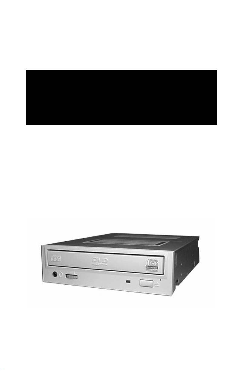
CD-RW/DVD-ROM DRIVE
Instruction Instructions
For the following Driv e :
SD-R1102
TOSHIBA AMERICA ELECTRONIC COMPONENTS, INC.
STORAGE DEVICE DIVISION
35 Hammond
Irvine, CA 92618
Contents of this manual are subject to change without prior notice.
© 2001 TOSHIBA AMERICA ELECTRONIC COMPONENTS, INC.
All rights reserved
Printed in USA
P/N 460021-A0
Page 4

You have just purchased one of the most advanced storage technologies
available. As with any new technology , you must r ead, and follow all set-up
and usage instructions in the applicable user guides and/or manuals enclosed.
WARNINGS
Operating this optical disk drive (the “Equipment”) outside its rated capacities and specifications may cause electrical overload, excessive heat, malfunction, erroneous operation,
and/or performance degradation. Please handle the Equipment properly in compliance
with the warnings provided below.
IF Y OU DO NOT COMPLY WITH THESE WARNINGS AND NOTICES, TOSHIBA
CANNOT GUARANTEE THE SAFETY, RELIABILITY, AND PERFORMANCE
OF THE EQUIPMENT AS IS EXPRESSLY PROVIDED IN THE EQUIPMENT’S
SPECIFICATIONS.
Manufacturers and resellers of computer systems (each, a “System”) using this Equipment and/or this Equipment itself should notify the end-users of the warnings provided
herein and ensure that they comply with these warnings.
1. This Equipment does not involve any over-current protection circuit. Y ou should
use an appropriate over-current protection circuit in any System to which this Equipment is connected. TOSHIBA SHALL NOT BE LIABLE FOR ANY DAMAGES TO THE SYSTEM WHICH DOES NO T HAVE ANY O VER-CURRENT
PROTECTION.
2. DO NOT disassemble or modify this Equipment. T oshiba makes no guar antee as to
the reliability, safety and performance of this Equipment when unauthorized disassembly and/or modification have occurred, whether or not such guarantees are set
forth in the specifications. TOSHIBA WILL NOT BE LIABLE FOR ANY
DAMAGES RESULTING FROM SUCH UNAUTHORIZED DISASSEMBLY OR MODIFICATION.
3. Read carefully and comply with this Product Specification to avoid the risk of data
error in the Equipment’s writing operation. Data error would be made by factors
other than this Equipment; for example, poor storage media, misuse of the Equipment, malfunction in a System. Check whether the original data is correctly copied
or stored upon completion of writing operation. TOSHIBA SHALL NOT BE
LIABLE FOR ANY DAMAGES RESULTING FROM SUCH DATA LOSS.
4. Make sure you take all necessary steps to protect your data, such as system backup
and/or mirroring disk subsystems. T aking these actions will help av oid the risk of
unexpected data loss or data corruption.
5. Manufacturers and resellers of Systems using this Equipment should consider the
System’s safety and its data integrity , in order to av oid the risk of damage caused by
data loss or data corruption, as well as problems or accidents caused by the System’s
malfunction.
Page 5

6. DO NOT use this Equipment in any system, such as medical equipment, where
personal injury or property damages could result from the Equipment’s malfunction,
unexpected data corruption, or data error in the reading operation.
7. When a disc cannot be ejected for some reason, you can use the ‘emergency eject’
mechanism. T o avoid risk of damages to the disc, turn the power of f and wait at least
one (1) minute before you eject the disc using the emergency eject mechanism.
NOTICE
T o avoid the risk of damage to the Equipment:
1. Always turn off the System power before mounting or removing the Equipment.
2. Always be sure to insert the DC power plug in correct direction.
3. Handle the Equipment only in electrostatically safe environment and do not touch
connecting terminals with bare hands when you attach or detach the Equipment
from other products.
4. DO NO T do any of the following. T aking any of the follo wing actions will damage or
destroy the Equipment or the disc, and could cause data loss or corruption:
4.1 DO NOT use storage media (CD’s / DVD’s) that are not the
correct size or shape, or which do not meet the minimum formatting requirements set forth in section 3.1.(1) of this Product
Specification.
4.2 DO NOT insert more than one (1) CD or DVD disc into the
drive at any time.
4.3 DO NOT load or eject any CD or DVD disc with force.
4.4 DO NOT eject a CD or DVD disc while the drive is in operation.
4.5 DO NOT insert anything else into the drive other than a CD or
DVD disc.
5. Before you carry or move the Equipment, always ensure that the disc tray is in the
“closed” position to avoid the risk of damages to the Equipment. If the tray is open,
turn on the Equipment and push the eject button to close the disc tray . Note that the
internal workings of the Equipment are not completely stabilized for moving if you
close the disc tray while power is not on.
Page 6

Table of Contents
Checking your Kit Packaging ...................................................................... 1
System Requirements.................................................................................... 1
Setting Jumpers ............................................................................................. 2
Placing CD-RW/D VD-R OM inside your computer ...................................... 2
Connecting Cables ........................................................................................ 3
IDE BUS (data) Cable ............................................................................... 3
Power Cable .............................................................................................. 4
Audio Cable .............................................................................................. 4
Completing Installation ................................................................................ 5
A TAPI CD/DVD Software Driver .............................................................. 5
VOB InstantCD/DVD Software ................................................................. 5
CyberLink Power D VD ............................................................................. 6
CD-RW/D VD-ROM F ront Panel ................................................................... 6
CD-RW/D VD-R OM Back Panel .................................................................... 6
Specifications................................................................................................ 7
Technical Support ......................................................................................... 8
CAUTION!
• REFLECTIVE OBJECTS SHOULD NOT BE PLACED IN THE DISK
SLOT DUE TO POSSIBLE HAZARDOUS
RADIATION EXPOSURE.
• USE OF CONTROLS, ADJUSTMENTS, OR PROCEDURES OTHER
THAN SPECIFIED IN THIS MANUAL MAY RESULT IN HAZARDOUS RADIATION EXPOSURE.
Version Date Published Revised Contents
01 April 2001 Initial release
Page 7

Congratulations on your purchase of a T oshiba CD-R W/D VD-ROM dri ve and Kit.
The following information will help you in the simple installation of your new
CD-RW/D VD-ROM dr ive.
CHECKING YOUR KIT PACKAGING
Please unpack your CD-RW/DVD-ROM kit, and assure that you have the following items:
l T oshiba CD-R W/DVD-R OM Drive
l CD-R Blank Media CD
l CD-RW Blank Media CD
l CyberLink PowerD VD™ Software
l VOB InstantCD/D VD Software CD
l CD-RW/D VD-R OM Installation Instructions (this manual)
l Quick Start Guide
l Mounting screws (4)
l IDE BUS cable
l DVD/CD sound cable
Additional items you may need that are not included in the kit are:
l Phillips Screwdriver
l Mounting hardware (i.e. some computer systems use mounting rails).
SYSTEM REQUIREMENTS
The CD-RW/D VD-R OM kit requires the following:
✔ At least 55MB of free hard disk space
✔ At least 32MB of RAM
✔ *Pentium II processor at 266MHz or higher or....
*Celeron 300A processor or higher or....
*K6-2 processor at 300MHz or higher
✔ Display card supporting DirectDraw
✔ 16-bit or better sound card
✔ Microsoft™ Windows 95 or higher
✔ Amplified stereo speakers
* These requirements are only required if you are using the CyberLink PowerDVD
software for movie playback. Toshiba’s CD-R W/D VD-ROM dri ve will work as
a CD-ROM, D VD-ROM and CD-R W when using a lo wer speed Pentium system.
™
1
Page 8
The following steps must be performed to properly install your CD-RW/DVDROM.
● Set drive’s jumpers
● Connect audio cable
● Attach IDE BUS cable
● Connect power cable
● Mount CD-RW/D VD-ROM
● Install CyberLink PowerD VD™ software (used for viewing D VD movies)
● Install V OB InstantCD/D VD software (used for recording CDs)
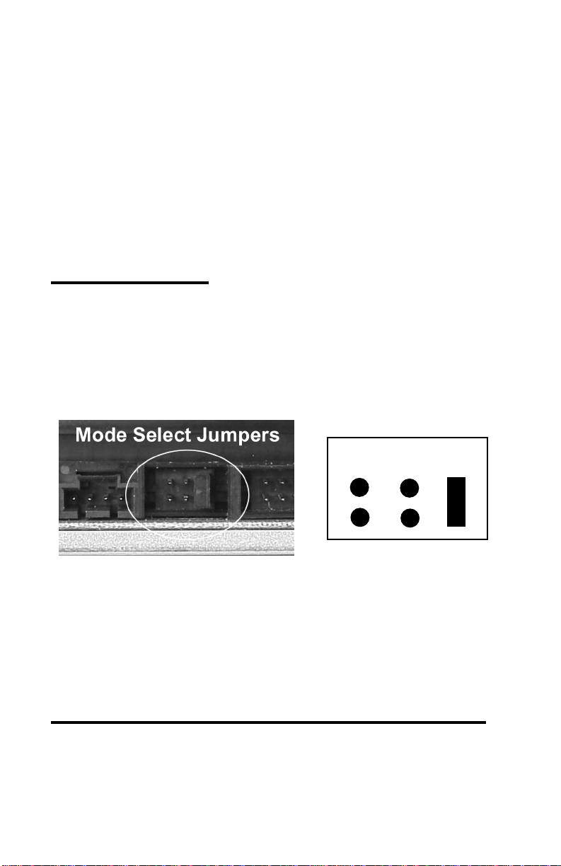
SETTING JUMPERS
The mode select jumpers are six (6) straight angle pins located on the rear of the
CD-RW/D VD-R OM. By placing a jumper on the pins, you can select the following
functions:
CS: – Drive is configured using host interface signal CSEL
SL: – Configures drive as Slave
MA: – Configures drive as Master (default mode)
C
S
S
L
M
A
Mode Select Jumpers
In most installations, jumper should remain in MA (Master) position (factory
default). It is recommended that you install your CD-RW/DVD-ROM only on the
secondary IDE BUS. If you are installing on primary IDE BUS, your hard drive
would then be the Master, and you should set your CD-RW/DVD-ROM to the
Slave position (SL).
PLACING CD-RW/DVD-ROM INSIDE YOUR COMPUTER
Now that you have set your drive’s jumpers, you are ready to install your
CD-RW/D VD-ROM inside your computer .
IMPORTANT: Disconnect power from your computer system before
☞☞
☞
☞☞
beginning installation.
2
Page 9

1. Remove computer cover and faceplate if required (refer to your computer
system’s manual for remo v al information).
2. If the CD-RW/DVD-ROM is replacing a CD-ROM, disconnect all connectors
and remove the CD-ROM presently installed in your system.
3. Your Toshiba CD-RW/DVD-ROM can be placed in any free half-height drive
slot at the front of your computer. (It can be mounted horizontally or vertically .)
4. Carefully start sliding the CD-RW/DVD-ROM into the opening with the disc
tray facing the front of the computer. Befor e you push the drive all the way in
you will need to connect the IDE BUS cable, audio cable and the power cable
to the back of the drive.
CONNECTING CABLES
Cable Locations on Rear of CD-RW/DVD-ROM
IDE BUS (Data) Cable - Most computer system have a primary and secondary
IDE BUS cable already installed (an IDE BUS cable is include with your kit if your
system does not have a secondary IDE BUS cable).
If you are replacing a CD-ROM: connect the CD-R W/D VD-ROM dri ve using the
BUS cable that the CD-ROM was connected to. Insure that the jumper setting of
the CD-RW/D VD-R OM is the same as the CD-R OM dri ve you are replacing.
If the CD-RW/DVD-ROM is not replacing a CD-ROM and/or is in addition to a
CD-ROM: locate the secondary IDE BUS cable in your system. If your system
does not have a secondary IDE BUS cable installed, you will need to install the
IDE BUS cable that was included with your kit.
Installing secondary IDE BUS cable: locate the secondary IDE BUS connector on your system’s motherboard (refer to your system’s documentation for
location). Connect one end of the IDE BUS cable to motherboard, assuring
that it is keyed properly and that cable’s colored edge is aligned with Pin 1.
3
Page 10

Connect secondary IDE BUS cable to CD-R W/DVD-R OM drive, assuring that pin
1 of the cable (side with red stripe) is connected to pin 1 on the drive.
• If the CD-RW/DVD-ROM is the only drive connected on the secondary IDE
BUS cable: connect drive to the last set of pins on IDE BUS cable.
• If there is a device (i.e. CD-ROM) connected to the secondary IDE BUS
cable: connect CD-RW/DVD-R OM to the open middle connector . The CD-
R W/DVD-ROM drive should then be jumpered to SL (sla ve) position.
If the CD-RW/D VD-ROM is to be the slave on the Primary B US: connect the CD-
RW/D VD-R OM to the open connector on the primary IDE BUS cable. The CD-RW/
DVD-ROM drive should be jumpered to the SL (sla ve) position. Note: the primary
IDE BUS cable, in most cases, will be connected to your hard drive. The hard
drive will be the Master on the primary BUS.
Power Cable - Inside your computer system, locate an unused power supply cable.
Connect the power cable to the power socket at the back of the CD-RW/DVDROM. One side of the plug has chamfered edges, so the power connector fits only
one way . Push plug completely into the socket making sure the plug fits correctly.
Audio Cable - Connecting your CD-RW/DVD-ROM to your sound card allows
you to play audio CDs on your computer (speakers or headphones are also needed).
If the CD-RW/D VD-ROM is in addition to a CD-R OM: If you choose to have both
a CD-ROM and CD-RW/DVD-ROM installed in your system, in most circumstances, only one audio cable can be used (there are some sound cards that will
allow you to have two audio connections). You must decide which device you
would like to hear audio from and connect the audio cable from the sound card to
the CD-ROM or CD-RW/DVD-ROM (DVD audio is transmitted through the data
cable, not the audio cable).
If the CD-RW/D VD-ROM is to be the only CD-R OM device in your system:
• If replacing a CD-ROM that had an audio cable connection: connect CDRW/DVD-ROM drive to the audio cable that the CD-ROM was connected.
Cable connects to the analog audio connector at the left rear of the CD-R W/
DVD-ROM (see Cable Location photo on page 3 for location).
• If you do not have an audio cable presently in your system: connect the CDRW/DVD-ROM using the audio cable that was included with this kit. Connect one end to your sound card and the other end to the analog audio connector at the left rear of the CD-R W/DVD-R OM (see Cable Location photo on
page 3 for location). Refer to the instructions which came with your sound
card for details on any sound-driver software required.
4
Page 11

COMPLETING INSTALLATION
After you have connected all the necessary cables, push the CD-RW/DVD-ROM
completely into the computer’s drive slot. Mount the drive per your computer’s
instructions using the screws included in your kit. If you are using other screws,
assure that the screw length does not exceed 3±0.5mm (measured from outside
surface of side or bottom of CD-RW/DVD-ROM to tip of screw). Replace the
computer cover and all outer screws.
ATAPI CD/DVD Software Driver:
T oshiba’ s CD-RW/DVD-R OM driv es do not require any unique device dri v ers for
Windows '95/'98/2000/WinMe/NT. After installing your drive and re-booting,
your system should recognize your drive. Win '95/'98/2000/WinMe/NT operating
systems support all Toshiba ATAPI CD-R W, CD-ROM and DVD-ROM drives natively.
VOB InstantCD/DVD Software:
To install software insert the installation CD into your newly installed drive. If
“Autorun” is enabled on your system, the Installation window will appear automatically . If it does not appear , go to Windows Start menu, select “Run” and type
d:\setup.exe (substitute the appropriate letter of your new drive for d:). From
the Installation window select InstantCD/DVD and follow the installation instruc-
tions that appear on your screen. For additional information on this software,
please refer to the documentation found on the VOB “InstantCD/DVD” CD.
InstantDisc - This easy to use software enables you to create your own CDs.
InstantBackup - Easy to use backup solution with support for CD-R(W), DVD-
RAM, and DVD-R(W) drives. Includes compression, encryption, spanning and
scheduled backups.
InstantCopy - Professional CD Duplication program including DAO-RAW support, easy to use profiles and On-the-Fly Data Processing.
InstantWrite - The only complete UDF packet writing software. Supports CDR(W), DVD-RAM and DVD-R and all UDF levels up to 2.01. With easy to use
format wizard and Defragmentation utility.
InstantMusic - Easy to use 16 track harddisc recording studio. Song composing
made easy . Includes real-time mixer , about 1000 high quality samples and v arious
effect filters.
InstantVideo - Creates VideoCDs- and SuperVideoCDs that can be played back in
almost any DVD-Player. AVIs are automatically encoded to the correct MPEG-1
format.
5
Page 12

CyberLink PowerDVD™:
CyberLink PowerDVD™ is a high-quality, pure-software DVD player that brings
high-quality movies and karaoke into your multimedia PC. You can playback
high resolution DVD titles or MPEG-2 files with superb MPEG-2 video and Dolby
AC-3 audio quality.
T o install, insert CyberLink PowerD VD™ into your newly installed CD-R W/DVDROM. Go to W indows Start menu, select “Run” and type d:\setup.exe (substitute the appropriate letter of your CD-RW/DVD-ROM drive for d:). Follow the
installation instructions on screen. For additional information on using this software, please refer to the PowerD VD™ Help file (if you have opened PowerDVD
software, click “?”).
CD-RW/DVD-ROM FRONT PANEL
The photo illustrates the following features of the SD-R1102 CD-R W/ D VD-ROM
front panel:
Q
Headphone Jack
R
Volume Control
S
Loading Tray
T
Busy Light
U
Eject Button
V
Emergency Eject Hole
™
CD-RW/DVD-ROM BACK PANEL
The photo below illustrates the following features of the SD-R1102 CD-R W/D VDROMs back panel:
Q
Digital Audio Out Connector
R
Analog Audio Out Connector
S
Mode Select Jumper
6
T
A TAPI Connector
U
Power Connector
Page 13

SPECIFICATIONS
DATA CAPACITY
(bytes/block)
ROTATIONAL SPEED
DVD: 2,048
CD: 2,048 (mode 1)
DVD: 5,053rpm (3.3-8X)
SD-R1102
2,336 (mode 2)
DVD-R:1,100-2,800rpm (2X)
CD: 6,849rpm (13.8-32X)
CD-RW:4,281rpm (8.6-20X)
CD-R,CD-RW: 1,700- 3,960rpm (8X)
SUSTAINED DATA
TRANSFER RATE
DVD: 4,476 - 10,816KB/sec
CD: 2,070 - 4,800KB/sec (mode 1)
2,359 - 5,472KB/sec (mode 2)
ACCESS TIME (Typ.)
Avg. Random Access
Avg Random Seek
Avg. Full Stroke
DVD CD
130ms 100ms
120ms 95ms
200ms 160ms
DATA BUFFER 2Mbytes
POWER SUPPLY +5v, +12v
MTBF 100,000 hours
DIMENSIONS (Wx H x D) 5.7” x 1.6” x 7.6” (146mm x 41.5mm x 193mm)
WEIGHT 0.58lbs ( 0.98kg)
MOUNTING ORIENTATION ±10° vertical / ±20° horizontal
TECHNICAL SUPPORT
Technical support can be obtained by calling 949/455-0407 or by sending an
email to: toshibadpd@teleplan-ventura.com or visiting our website at:
http://www.sdd.toshiba.com
FCC DECLARATION OF CONFORMITY
This equipment has been tested and found to comply with the limits for a class B digital device, pursuant to part
15 of the FCC Rules. These limits are designed to provide reasonable protection against harmful interference
in a residential installation. This equipment generates, uses and can radiate radio frequency energy, and if not
installed and used in accordance with the instructions, may cause harmful interference to radio communications.
However, there is no guarantee that interference will not occur in a particular installation. If this equipment does
cause harmful interference to radio or television reception, which can be determined by turning the equipment
off and on, the user is encouraged to try to correct the interference by one or more of the following measures:
• Re-orient or relocate the receiving antenna.
• Increase the separation between the equipment and receiver.
• Connect the equipment into an outlet on a circuit different from that to which the receiver is connected.
• Consult the dealer or an experienced radio/TV technician for help.
This equipment has been certified to comply with the limits for a class B computing device, pursuant to FCC
Rules. In order to maintain compliance with FCC regulations, shielded cables must be used with this equipment.
Operation with non-approved equipment or unshielded cables is likely to result in interference to radio and TV
reception. The user is cautioned that changes and modifications made to the equipment without the approval of
the manufacturer could void the user's authority to operate this equipment.
LASER CAUTION
This appliance contains a laser system and is classified as a "CLASS 1 LASER PRODUCT". To use this model
properly, read this Owner's Manual carefully and keep this manual for future reference. In case of any trouble with
this model, please contact your nearest "Authorized Repair Center". To prevent direct exposure to the laser beam,
do not try to open the enclosure
7
Page 14

WARRANTY INFORMATION
Toshiba America Electronic Components, Inc. (“TAEC”) warrants that all products will, upon delivery by TAEC to the customer in new condition, be free from
defects in material and workmanship for a period of twelve (12) months after
delivery. TAEC warrants that spare Parts and Accessories will be free from defects
in material and workmanship for a period of ninety (90) days. These warranties
are effective from the date of shipment by TAEC to the original purchaser and
will be extended only to that original purchaser. TAEC will, at its option, repair
or replace the defective item under warranty in accordance with TAEC’s published Repair Policy and Procedure.
This warranty is void: (a) if the Products are used under other than normal use
and maintenance conditions, (b) if the Products are modified or altered, unless
the modification or alteration is expressly authorized by TAEC, (c) if the equipment is subject to abuse, neglect, lightning, electrical fault, or accident, (d) if the
Products are repaired by someone other than TAEC, (e) if the serial numbers of
the Products are defaced or missing, or (f) if the Products are installed or used in
combination or in assembly with products not supplied by and which are not
compatible or of inferior quality, design or performance.
This Warranty shall constitute the sole and exclusive liability of the TAEC, it's
successors or assigns, in connection with the goods purchased and is in lieu of all
other Warranties, expressed or implied, including but not limited to any implied
warranty of merchantability, fitness for a particular purpose or fitness for use, and
all other obligations or liabilities of TAEC, it's successors or assigns.
Under no circumstances will the customer or any user or other person be entitled
to any direct, indirect, special, consequential, or exemplary damages, for Breach
of Contract, Tort, or otherwise. Under no circumstances will any such person be
entitled to any sum greater than the purchase price paid for the product that is
malfunctioning.
This warranty does not apply to expendable parts such as fuses, filters, removable media, and other such parts classified by Seller as expendable.
• All repairs will be performed at T AEC’ s Repair f acility , exce pt for repairs made at the
Purchaser’s site, as specif ically agreed by T AEC in writing .
• Purchaser shall bear the cost of shipping to T AEC’ s facility those items that fail w hile
under warranty . T AEC shall bear the cost of return shipment to Purchaser’ s facility .
• Repairs on products that fail during the new product warranty period are warranted for the
remainder of the new product warranty period or 90 days, whichever is the greatest.
• The repair of product that failed after the expiration of the original warranty period is
warranted for ninety days from the date the repaired item is shipped back to the customer .
• T o obtain service under this warranty , the Purchaser must bring the malfunction of the
Product to the attention of T AEC within the twelve (12) month per iod and no later than
thirty (30) days after such malfunction, whichever occurs first. Failure to bring the malfunction to the attention of T AEC, within the prescribed time, will result in the Purchaser
being not entitled to warranty service.
8
Page 15

Page 16

460018-C0
P/N 460021-A0
 Loading...