

Toshiba SD-R1002 User Manual

TOSHIBA AMERICA INFORMATION SYSTEMS
STORAGE DEVICE DIVISION
IRVINE, CALIFORNIA
SD-R1002
CD-RW/DVD-ROM COMBO DRIVE
USER MANUAL

CONTENTS
Introduction..............................................................................1
Setup ........................................................................................3
Using the Combo Drive...........................................................6
Troubleshooting.......................................................................9
Specifications ........................................................................10
Drive Connectors................................................................... 13

INTRODUCTION – SD-R1002
General Features
CD-RW disc write/rewrite at 1X, 2X and 4X
3-way Disc Eject (eject button, software, emergency eject hole)
Average Random Access Time
CD 110ms
DVD-ROM 160ms
Horizontal or Vertical Mount
2MB Buffer
Playback interchangeability for CD-ROM and DVD-ROM discs
Regionalization (RPC2 compliance) (DVD)
BUS Interface - ATAPI
Types of Disc Formats Supported - Write:
• Applicable Write Format CD-R, CD-RW: Disc at once, Track at once, Session at once,
Packet write
• Applicable Write disc CD-R, CD-RW: CD-DA, CD+(E)G, CD-MIDI, CD-ROM, CD-ROM XA,
CD-I, CD-I Bridge (Photo-CD, Video-CD), Multisession CD (Photo-CD, CD-EXTRA)DVD-R
(Playback only)
Types of Disc Formats Supported - Read:
DVD:
• DVD-ROM
• DVD-R (Playback only)
CD:
• CD-DA, CD+(E)G, CD-MIDI, CD-TEXT, CD-ROM, CD-ROM XA, CD-I, CD-I Bridge (Photo-
CD, Video-CD), Multi-session (Photo-CD Disc, CD-Extra, CD-R, CD-RW), CD-R (read), CDRW (read)
1
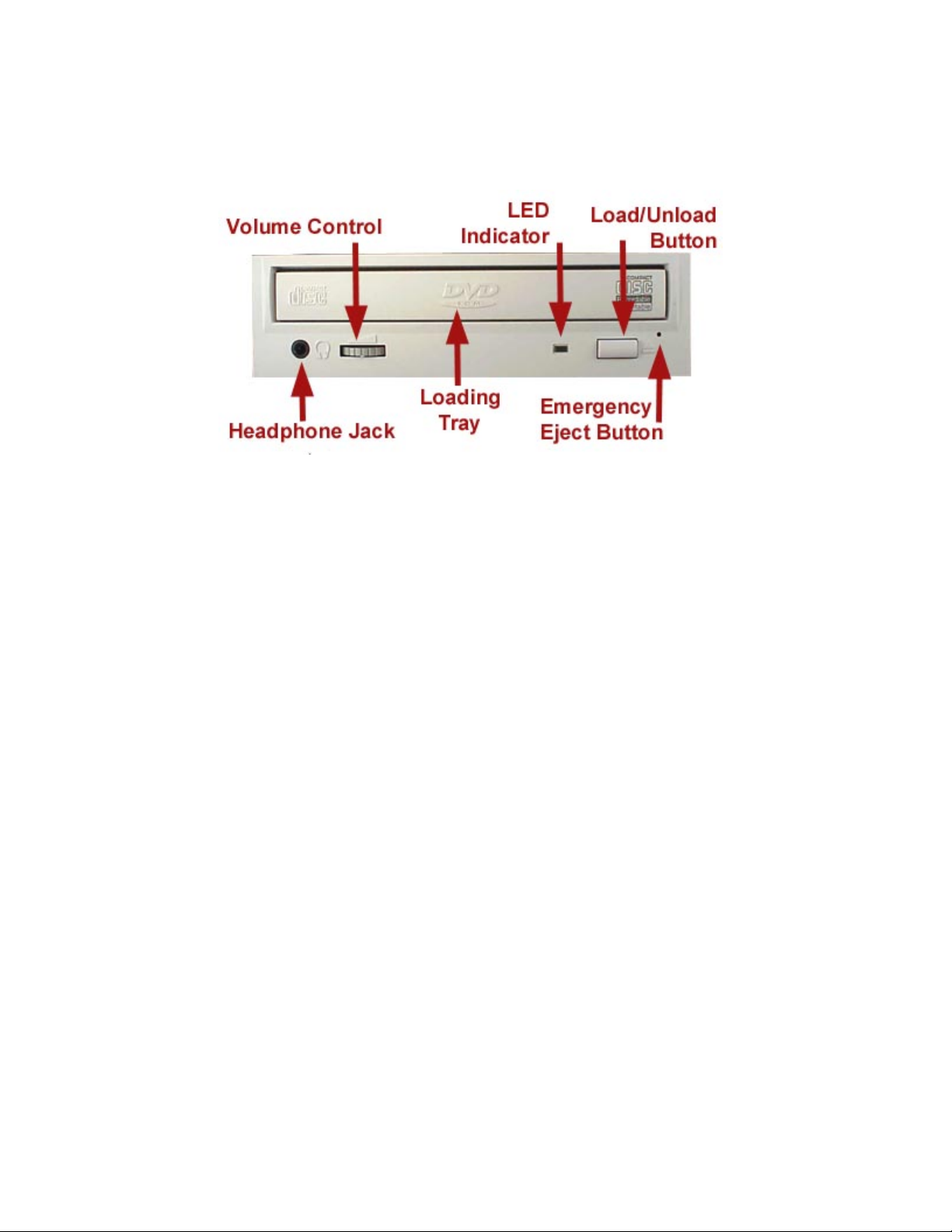
Front Panel
Figure 1.SD-R1002 DVD Writeable Drive Front Panel
Loading Tray Load disc using tray.
LEDs The LED lights green or amber when the drive is operating (LED is amber
when drive is writing.)
Load/Unload Button The Load/Unload button is used to open the disc tray so you can install or
remove a disc.
Emergency Eject Hole The emergency eject hole is to be used only when the Loading Tray will not
open when Eject button is pressed
SETUP – SD-R1002
The following steps must be performed to properly install your drive:
• Set Drive Jumper Settings
• Connect Audio Cable
• Attach IDE BUS Cable
• Attach Power Cable
• Mount Drive
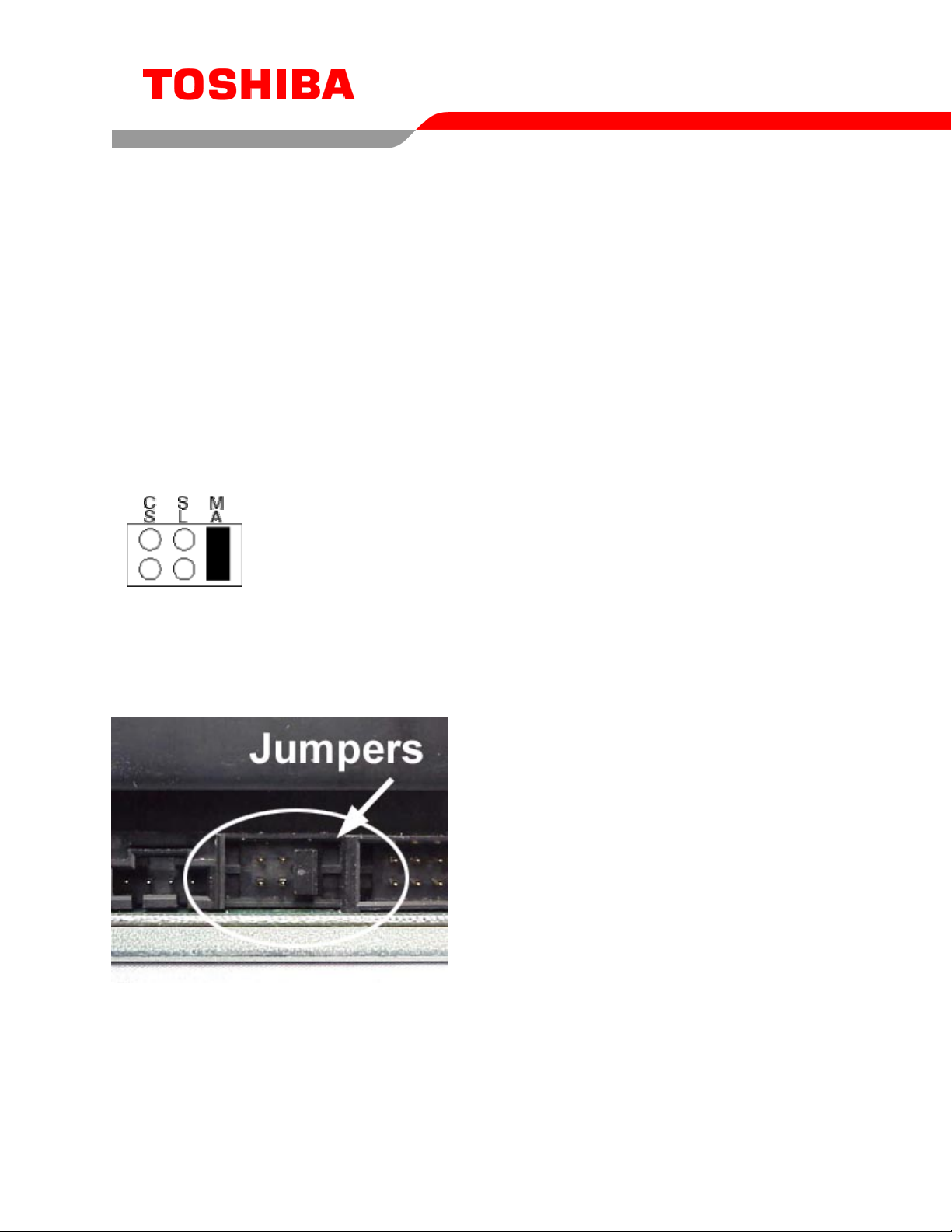
Jumper Settings
The mode select jumpers are 6 straight angle pins located on the rear of the Combo drive.
By placing a jumper on the pins, you can select the following functions:
CS
SL Configures drive as Slave
MA Configures drive as Master (default mode)
In most installations, jumper should remain in the MA position (factory default). It is recommended that
you install your Combo drive only on the secondary IDE BUS. If you are installing on primary IDE BUS,
your hard drive would then be the Master, and you should set your Combo drive to the Slave position
(SL)
Drive is configured using host interface signal CSEL
Figure 1.Mode Select Jumper
3
Figure 2.Jumper Locations
 Loading...