

DVD HOME
THEATER SYSTEM
SD-43HT
OWNER’S MANUAL
Before connecting, operating or adjusting this product, please
read this instruction booklet carefully and completely.
V I D E O
COMPACT
DIGITAL AUDIO
COMPACT
DIGITAL VIDEO

Safety Precautions
Important Safety Instructions
CAUTION
RISK OF ELECTRIC SHOCK
DO NOT OPEN
CAUTION: TO REDUCE THE RISK
OF ELECTRIC SHOCK DO NOT REMOVE COVER (OR
BACK) NO USER-SERVICEABLE PARTS INSIDE
REFER SERVICING TO QUALIFIED SERVICE
PERSONNEL.
This lightning flash with arrowhead symbol within
an equilateral triangle is intended to alert the user
to the presence of uninsulated dangerous voltage
within the product’s enclosure that may be of
sufficient magnitude to constitute a risk of electric
shock to persons.
The exclamation point within an equilateral
triangle is intended to alert the user to the
presence of important operating and maintenance
(servicing) instructions in the literature
accompanying the appliance.
WARNING: TO REDUCE THE RISK OF FIRE OR ELECTRIC
SHOCK, DO NOT EXPOSE THIS PRODUCT TO RAIN OR
MOISTURE.
CAUTION: TO PREVENT ELECTRIC SHOCK, MATCH WIDE
BLADE OF PLUG TO WIDE SLOT, FULLY INSERT.
ATTENTION: POUR ÉVITER LES CHOC ÉLECTRIQUES,
INTRODUIRE LA LAME LA PLUS LARGE DE LA FICHE
DANS LA BORNE CORRESPONDANTE DE LA PRISE ET
POUSSER JUSQU'AU FOND.
WARNING: Do not install this equipment in a confined space
CAUTION:
This Digital Video Disc Player employs a Laser System.
To ensure proper use of this product, please read this owner’s
manual carefully and retain for future reference, should the unit
require maintenance, contact an authorized service locationsee
service procedure.
Use of controls, adjustments or the performance of procedures
other than those specified herein may result in hazardous
radiation exposure.
To prevent direct exposure to laser beam, do not try to open
the enclosure. Visible laser radiation when open. DO NOT
STARE INTO BEAM.
CAUTION: The apparatus shall not be exposed to water,
dripping or splashing and that no objects filled with liquids,
such as vases, shall be placed on the apparatus.
such as a bookcase or similar unit.
CLASS 1 LASER PRODUCT
KLASSE 1 LASER PRODUKT
LUOKAN 1 LASER LAITE
KLASS 1 LASER APPARAT
CLASSE 1 PRODUIT LASER
FCC WARNING: This equipment may generate or use
radio frequency energy. Changes or modifications to this
equipment may cause hermful interference unless the
modifications are expressly approved in the instruction
manual. The user could lose the authority to operate this
equipment if an unauthorized change or modification is
made.
REGULATORY INFORMATION: FCC Part 15
This product has been tested and found to comply with the
limits for a Class B digital device, pursuant to Part 15 of the
FCC Rules. These limits are designed to provide reasonable
protection against harmful interference when the product is
operated in a residential installation. This product
generates, uses and can radiate radio frequency energy
and, if not installed and used in accordance with the
instruction manual, may cause harmful interference to
radio communications. However, there is no guarantee that
interference will not occur in a particular installation. If this
product does cause harmful interference to radio or
television reception, which can be determined by turning
the product off and on, the user is encouraged to try to
correct the interference by one or more of the following
measures:
• Reorient or relocate the receiving antenna.
• Increase the separation between the product and receiver.
• Connect the product into an outlet on a cirucit different
from that to which the receiver is connected.
• Consult the dealer or an experienced radio/TV technician
for help.
Notes on copyrights:
It is forbidden by law to copy, broadcast, show, broadcast
via cable, play in public, or rent copyright material without
permission.
This product is equipped with copy protection measures
developed by Macrovision. Copy protection signals are
recorded on some discs. When recording these discs on a
VCR, picture noise will appear during playback.
This product incorporates copyright protection technology
that is protected by certain U.S. patent claims and other
intellectual property rights owned by Macrovision
Corporation and other rights owners. Use of this copyright
protection technology must be authorized by Macrovision
Corporation, and is intended for home and other limited
viewing uses only unless otherwise authorized by
Macrovision Corporation. Reverse engineering or
disassembly is prohibited.
SERIAL NUMBER: The serial number is found on the back
of this unit. This number is unique to this unit and not
available to others. You should record requested
information here and retain this guide as a permanent
record of your purchase.
Model No. ___________________________________
Serial No. ___________________________________
CAUTION: PLEASE READ AND OBSERVE ALL WARNINGS AND INSTRUCTIONS IN THIS OWNER’S MANUAL AND
THOSE MARKED ON THE UNIT. RETAIN THIS BOOKLET FOR FUTURE REFERENCE.
This set has been designed and manufactured to assure personal safety. Improper use can result in electric shock or fire
hazard. The safeguards incorporated in this unit will protect you if you observe the following procedures for installation, use,
and servicing. This unit does not contain any parts that can be repaired by the user.
DO NOT REMOVE THE CABINET COVER, OR YOU MAY BE EXPOSED TO DANGEROUS VOLTAGE. REFER
SERVICING TO QUALIFIED SERVICE PERSONNEL ONLY.
1. Read these instructions. - All these safety and
operating instructions should be read before the product
is operated.
2. Keep these instructions. - The safety, operating and
use instructions should be retained for future reference.
3. Heed all warnings. - All warnings on the product and in
the operating instructions should be adhered to.
4. Follow all instructions. - All operating and use
instructions should be followed.
5. Do not use this apparatus near water. - For example:
near a bath tub, wash bowl, kitchen sink, laundry tub, in
a wet basement; or near a swimming pool; and like.
6. Clean only with dry cloth. - Unplug this product from
the wall outlet before cleaning. Do not use liquid
cleaners.
7. Do not block any ventilation openings. Install in
accordance with the manufacturer’s instructions. -
Slots and openings in the cabinet are provided for
ventilation and to ensure reliable operation of the product
and to protect it from over- heating. The openings should
never be blocked by placing the product on a bed, sofa,
rug or other similar surface. This product should not be
placed in a built-in installation such as a bookcase or
rack unless proper ventilation is provided or the
manufacturer’s instructions have been adhered to.
8. Do not install near any heat sources such as
radiators, heat registers, stoves, or other apparatus
(including amplifiers) that produce heat.
9. Do not defeat the safety purpose of the polarized or
grounding-type plug. A polarized plug has two
blades with one wider than the other. A grounding
type plug has two blades and a third grounding
prong. The wide blade or the third prong are
provided for your safety. If the provided plug does
not fit into your outlet, consult an electrician for
replacement of the obsolete outlet.
10. Protect the power cord from being walked on or
pinched particularly at plugs, convenience
receptacles, and the point where they exit from the
apparatus.
11. Only use attachments/accessories specified by the
12. Use only with the cart, stand, tripod, bracket, or
table specified by the manufacturer, or sold with
apparatus. When a cart is used, use caution when
moving the cart/ apparatus combination to avoid
injury from tip-over.
13. Unplug this apparatus during lightning storms or
when unused for long periods of time.
14. Refer all servicing to qualified service personnel.
Servicing is required when the apparatus has been
damaged in any way, such as power-supply cord or
plug is damaged, liquid has been spilled or objects
have fallen into the apparatus, the apparatus has
been exposed to rain or moisture, does not operate
normally, or has been dropped.
15. When you use headphones, keep the volume at a
moderate level. If you use the headphones
continuously with high volume sound, it may cause
hearing damage.
16. Do not overload wall outlets; extension cords, or
integral convenience receptacles as this can result
in a risk of fire or electric shock.
17. Apparatus shall not be exposed to dripping or
splashing and no objects filled with liquids, such as
vases, shall be placed on the apparatus.
18. Keep your fingers well clear of the disc tray as it is
closing. Neglecting to do so may cause serious
personal injury.
19. Do not place a heavy object on or step on the
apparatus. The object may fall, causing serious
personal injury and serious damage to the
apparatus.
20. Do not use a cracked, deformed, or repaired disc.
These discs are easily broken and may cause
serious personal injury and apparatus malfunction.
manufacturer.
1 2
Contents
1
Before Use
PREPARATION
Safety Precautions ......................................................................................................................................1
Important Safety Instructions.......................................................................................................................2
Before Use...................................................................................................................................................4
Description ..................................................................................................................................................5
Remote Control ...........................................................................................................................................7
CONNECTIONS
Connecting the Speakers ............................................................................................................................9
Connecting to a TV......................................................................................................................................10
Connecting the FM and AM(MW/LW) Antennas .........................................................................................11
Connecting the Optical Equipment..............................................................................................................12
Before Using the DVD Player .....................................................................................................................13
P.SCAN(Progressive Scan) Function..........................................................................................................14
OPERATION
DVD Playback .............................................................................................................................................15
MP3/WMA CD Playback..............................................................................................................................17
Forward/Reverse Searching........................................................................................................................19
Slow Playback/Checking the Remaining Time............................................................................................20
Repeat Playback ........................................................................................................................................21
Disc Menu/Top Menu Function....................................................................................................................22
Selecting the Audio Language/Subtitle Language ......................................................................................23
Zoom/Angle Functions.................................................................................................................................24
JPEG File Playback.....................................................................................................................................25
Program Playback .......................................................................................................................................27
SETUP
Setup Functions...........................................................................................................................................29
General Setup .............................................................................................................................................30
Speaker Setup.............................................................................................................................................33
To set up Speaker Balance .........................................................................................................................35
Creating Realistic Sound Fields ..................................................................................................................36
Dolby Pro Logic II decoder ..........................................................................................................................37
RADIO OPERATION
Listening to the Radio..................................................................................................................................39
Presetting the radio stations........................................................................................................................40
MISCELLANENOUS
Sleep Function.............................................................................................................................................41
Using Headphone Jack ...............................................................................................................................41
Mute Function..............................................................................................................................................41
Cautions on Handling and Storing Discs.....................................................................................................42
Troubleshooting ..........................................................................................................................................43
Language Code List ....................................................................................................................................44
Specifications ..............................................................................................................................................45
Limited Warranty DVD Video Player ...........................................................................................................47
3
3
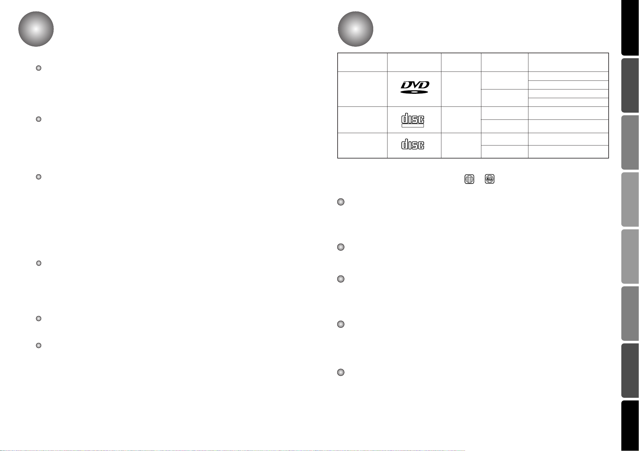
Disc Types
Marks
Recording
Types
Disc Size
5 inch
DVD
V I D E O
COMPACT
VIDEO-CD
DIGITAL VIDEO
COMPACT
AUDIO-CD
DIGITAL AUDIO
The region number of this DVD Home Theater is 1. If region numbers,which stand for their playable area, are
printed on your DVD Video Disc and you do not find or , disc playback will not be allowed by the
DVD Home Theater.
Notes on DVDs and Video CDs
Some playback operations of DVDs and Video CDs may be intentionally fixed by software manufacturers.
As this unit plays DVDs and Video CDs according to disc content designed by the software manufacturer,
some playback features of the unit may not be available, or other functions may be added.
Refer also to the instructions supplied with the DVDs and Video CDs. Some DVDs made for business
purposes may not be played on the unit.
DVD players and the discs are coded by region. These regional codes must match in order for the disc to
play. If the codes do not match, the disc will not play.
The Region Number for this player is given on the rear panel of the player.
(Your DVD player will only play DVDs that are labeled with identical region codes.)
Because of problems and errors that can occur during the creation of DVD software and or the manufacture of
DVD discs, Toshiba America Consumer Products, Inc., Toshiba Hawaii. Inc. and Toshiba of Canada Ltd. cannot
guarantee that this player will play every feature of every DVD bearing the DVD logo. As one of the creators of
DVD technology. Toshiba DVD players are manufactured to the highest standards of quality and, as a result,
such incompatibilities are very rare. If you happen to experience and difficulty playing a DVD on a Toshiba DVD
player, please feel free to call our Contact listed in “How to Obtain Warranty Services” page 47.
Note on DTS-encoded CDs
When playing DTS-encoded CDs, excessive noise may be exhibited from the analog stereo output.
To avoid possible damage to the audio system, turn down the volume before playing back such discs,
adjust the volume gradually, and keep the volume level low. To enjoy DTS Digital SurroundTM playback,
an external 5.1 channel DTS Digital SurroundTMdecoder system must be connected to the digital output
of the unit.
Notes
– Depending on the conditions of the recording equipment or the CD-R/RW disc itself, some CD-R/RW
discs cannot be played on the unit.
– The unit cannot play the CD-R/RW discs that contain no data, or contain different kinds of formatted
data other than MP3 and CD-DA data.
– Do not attach any seal or label to either side (the labeled side or the recorded side) of a disc.
– Do not use irregular shaped CDs (e.g., heart-shaped or octagonal). It may result in malfunctions.
– Playback of some DVD-R/RW discs may not be possible depending on the conditions of the recording
or the severity of scratches on the disc surface.
Audio + Video
3 1/2 inch
5 inch
Audio + Video
3 1/2 inch
5 inch
Audio
3 1/2 inch
Max. Playing Time
Approx. 240 min. (Single-sided)
Approx. 480 min. (Double-sided)
Approx. 80 min. (Single-sided)
Approx. 160 min. (Double-sided)
74 min.
20 min.
74 min.
20 min.
44
PREPARATION CONNECTIONS
OPERATION
SETUP
RADIO OPERATION
MISCELLANENOUS
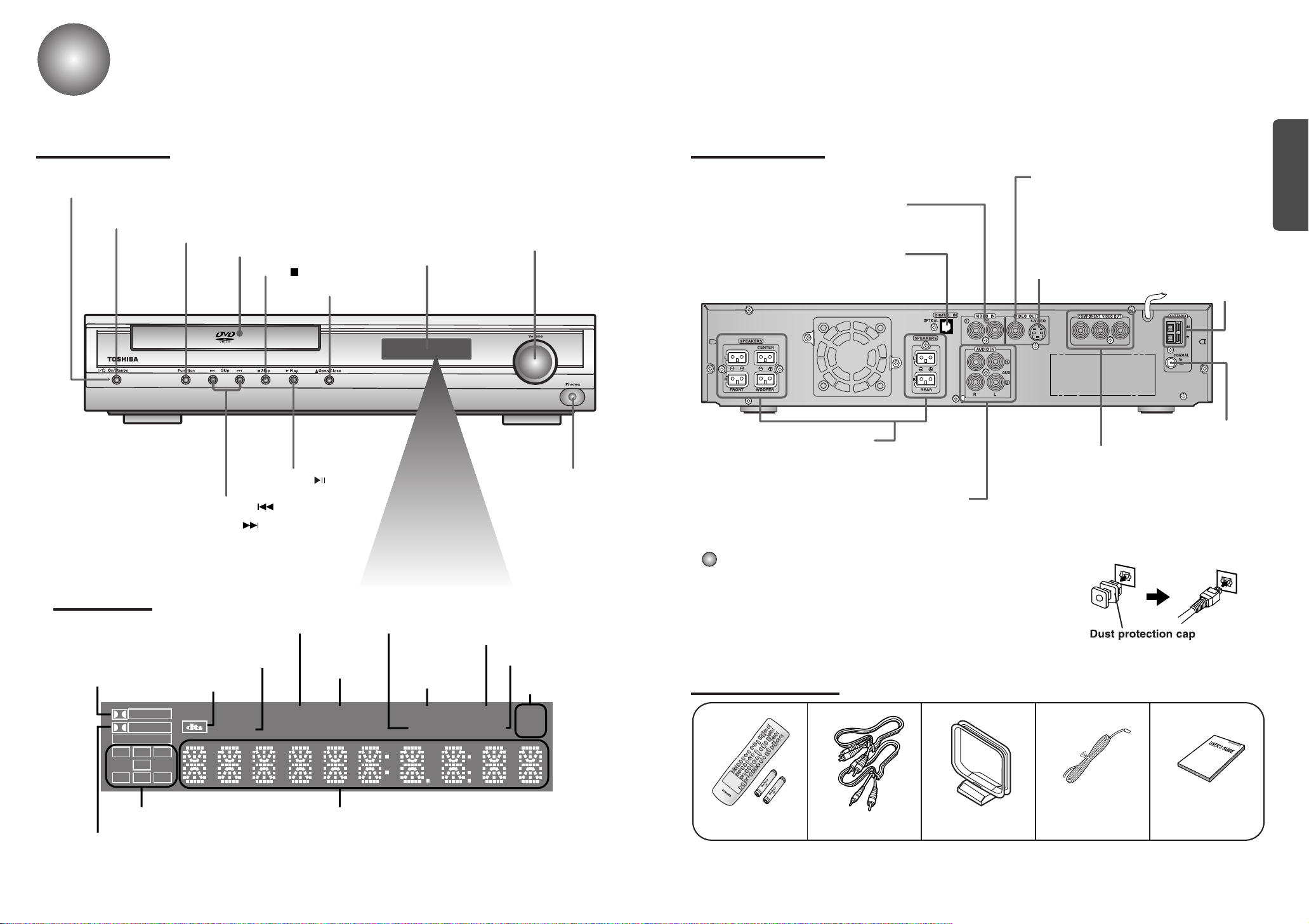
Description
PRO LOGIC
LINEAR PCM
TITLE
TUNED
PROGRAM PBC
MHZ
KHZ
DSP
ST
LCR
LS
LFE
SRS
D I G I T A L
P . SCAN
PREPARATION
Front Panel
On/Standby indicator
On/Standby button
Function button
Tuning Down & Skip ( ) buttons
Tuning Up & Skip ( ) buttons
Disc Tray
Stop ( ) button
Open/Close button
Play/Pause ( ) button
Display
Volume control
Headphone Jack
Rear Panel
External Video Component
Input Connectors
External Digital Component Input
Connector
Use this to connect external equipment
capable of digital output.
5.1 Channel Speaker
Output Terminals
External Audio Component
Input Connector
Video Output Connector
Connect the TV's video input jacks (VIDEO IN) to
the VIDEO OUT connector.
S-Video Output Connector
If the TV is equipped with an S-Video input
connector (S-VIDEO IN), connect it to the player's
S-Video output jack.
COMPONENT VIDEO
OUTPUT/INPUT jacks
Connect a TV with component
video inputs to these jacks.
AM Antenna
Connector
FM Antenna
Connector
Display
PRO LOGIC
indicator
DOLBY DIGITAL indicator
DTS Disc indicator
TUNER indicator
TITLE indicator
System Status DisplaySPEAKER indicator
P.SCAN
indicator
STEREO
indicator
indicator
PROGRAM
indicator
PBC
DSP indicator
RADIO FREQUENCY
indicator
Dust protection cap
Remove the dust protection cap from the OPTICAL DIGITAL IN
jack and connect the optical digital cable (not supplied) securely
so that the configurations of both the cable and the connector
match. Keep the dust protection cap and always reattach the cap
when not using the connector to protect against dust intrusion.
Accessories
Remote Control &
Batteries
Audio Cable/
Video Cable
User's ManualFM AntennaAM Antenna
65
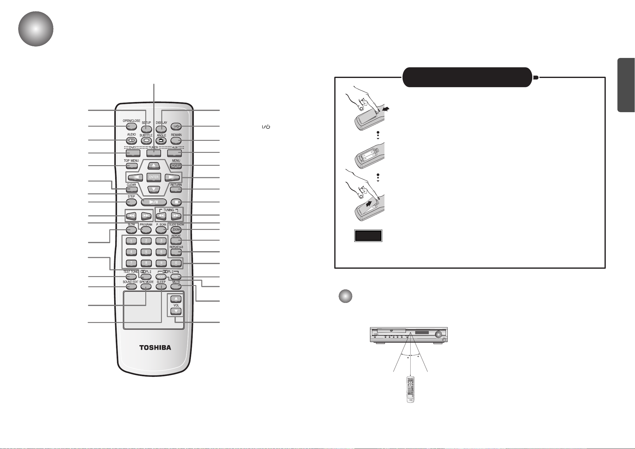
Remote Control
30
30
7~10m
PREPARATION
SETUP button
OPEN/CLOSE button
AUDIO button
DVD button
TOP MENU button
CLEAR button
PLAY/PAUSE button
STEP button
Tuning Preset/CD Skip button
PROGRAM button
SLOW button
DPL II button
TUNER button
DISPLAY button
ON/STANDBY ( ) button
REMAIN button
AUX button
MENU/DIGEST button
DIRECTION/ENTER button
RETURN button
STOP button
Tuning/CD Search button
P.SCAN button
SILDE SHOW/ZOOM button
REPEAT button
REPEAT A↔B button
Number(0~9) buttons
Caution
Insert Remote Batteries
Open the battery cover on the back of the remote control.
1
Insert two 1.5V AA batteries, paying attention to the correct
2
polarities (+ and –).
Replace the battery cover.
3
Follow these precautions to avoid leaking or cracking cells:
• Place batteries in the remote control so they match the polarity:(+) to (+)and (–)to (–).
• Use the correct type of batteries.Batteries that look similar may differ in voltage.
• Always replace both batteries at the same time.
• Do not expose batteries to heat or flame.
TEST TONE button
SOUND EDIT button
SPK MODE button
SLEEP button
DPL II EFFECT button
DPL II MODE button
MUTE button
TV Volume Control button
Range of Operation of the Remote Control
The remote control can be used up to approximately 23 feet/7 meters in a straight line. It can also be
operated at a horizontal angle of up to 30° from the remote control sensor.
7 8
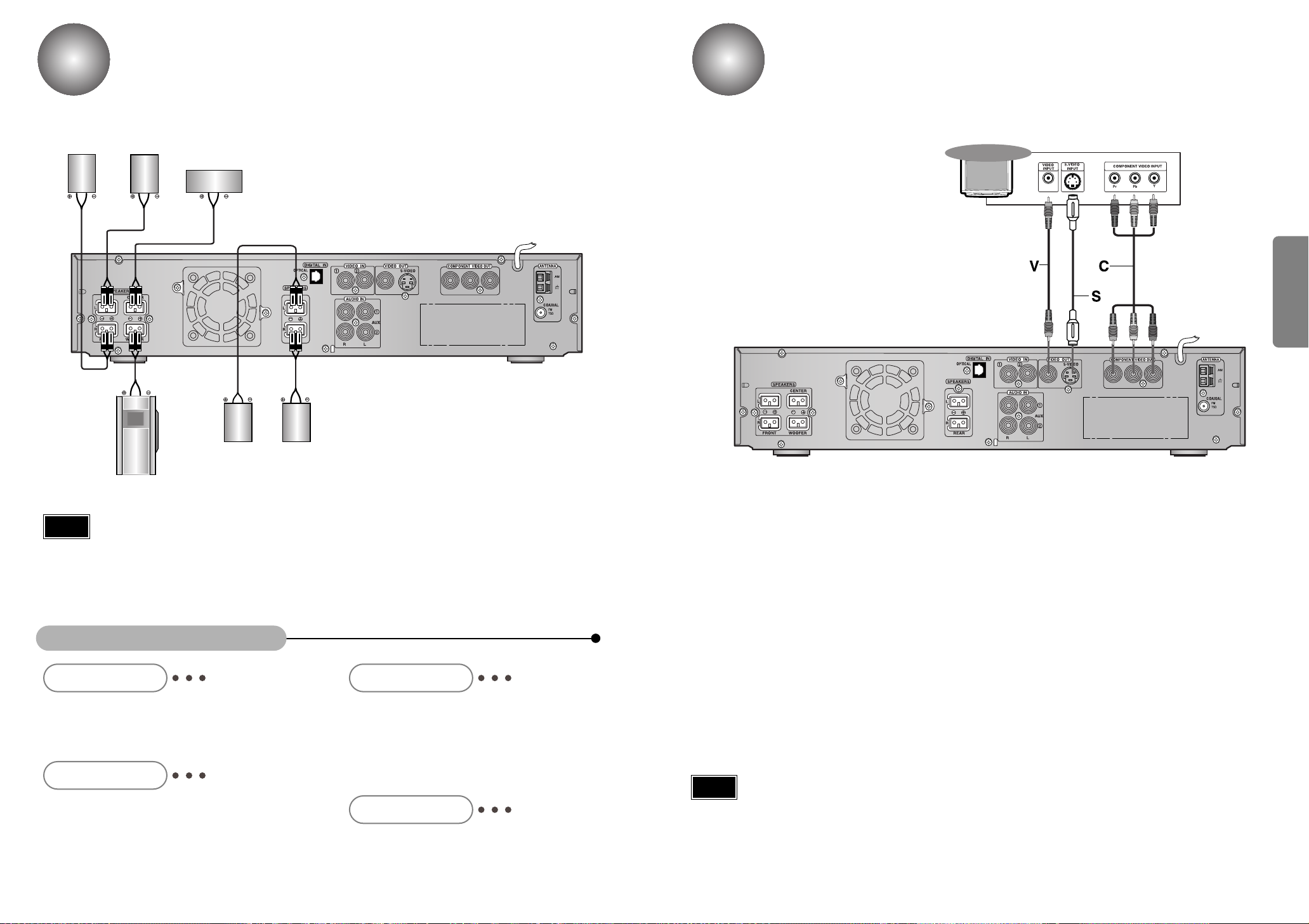
Connecting the Speakers
Rear of TV
Connecting to a TV
Right front speaker
Turn off the Power first and set the volume knob to low initially before connecting.
Left front speaker
Center speaker
Rear speaker
(Left Surround)
Rear speaker
(Right Surround)
Connect the speakers using the supplied speaker
•
cords by matching the colors of the terminals and
those of the cords.
To obtain the best possible surround sound, adjust
•
the speaker parameters (distance, level, etc.).
Please turn off the Power of your TV, DVD receiver and other equipment before doing
any connections. Set the volume to low initially.
CONNECTIONS
Subwoofer
Note
Be sure to match the speaker cord to the appropriate terminal on the components: + to + and
•
– to –. If the cords are reversed, the sound will be distorted and will lack bass.
If you use front speakers with low maximum input rating, adjust the volume carefully to avoid
•
excessive output on the speakers.
Do not disassemble the front cover of supplied speaker.
•
Ideal Speaker Placement
Front Speakers
Set the front speakers so that their tweeters
(high-range) are aligned at about ear level and at a
horizontal angle of 45° to the prime listening position.
Center Speaker
Ideally the center speaker should be positioned with its
top surface flush with the front speakers. However,
you may place the speaker either on top or near the
bottom of your TV set.
Rear Speakers
Set the rear speakers further back, parallel to the
walls, at 60 to 90 centimeters (2 to 3 feet) above prime
listening position ear level.
If the space behind the listening position is insufficient
(i.e., too close to the wall), place the rear speakers
facing each other on either side.
Subwoofer Speaker
Place the subwoofer at any convenient location
within the vicinity of the listening position.
Depending on your TV and other equipment you wish to connect, there are various ways you could connect the player.
Use one of the connections described below.
Video connection (Good)
Connect the VIDEO OUT jack on the DVD Receiver to the video in jack on the TV using
•
the video cable supplied (V).
S-Video connection (Better)
Connect the S-VIDEO OUT jack on the DVD Receiver to the S-Video in jack on the TV
•
using the optional S-Video cable (S).
Component Video (Color Stream®) connection (Best)
Connect the COMPONENT VIDEO OUT jacks on the DVD Receiver to the corresponding
•
in jacks on the TV using an optional Y Pb Pr cable (C).
Note
When the Progressive scan mode is selected, the VIDEO and S-VIDEO outputs do not feed
•
any signals. See page 16 to select Progressive Scan.
The signal of S-VIDEO OUT jack will output only when the function mode is selected to
•
CD/DVD.
9
10
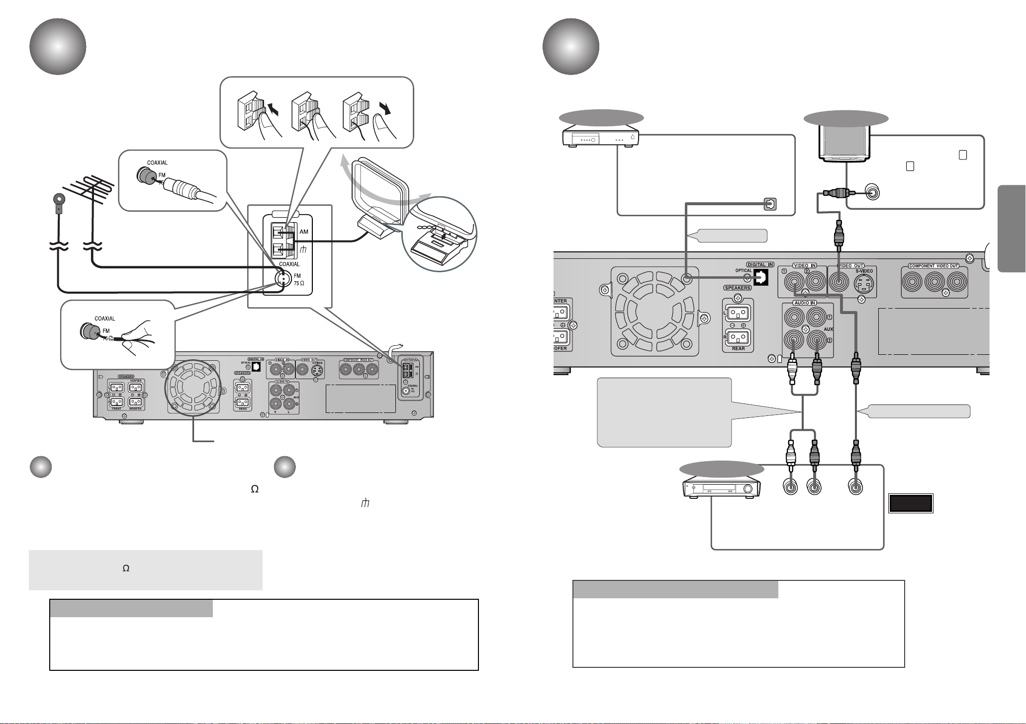
Connecting the FM and AM
ANTENNA
123
LR
DIGITAL OUT
VIDEO OUT
VIDEO IN
If FM reception is poor,
connect an outdoor FM antenna
(not supplied).
(
MW/LW
)
Antennas
If AM reception is
poor, connect an
outdoor AM
antenna(not
supplied).
AM Loop Antenna
(supplied)
Connecting the Optical Equipment
External Digital
Components
Example: CD recorders, MD (Mini Disc) D/A
For connection to external
equipment with digital output.
converters or other components equipped
with digital output jacks
(not supplied)
Optical Cable
TV
To view pictures from
external input (AUX 1 ,
AUX 2 ), first connect the
VIDEO IN jack and then
connect the VIDEO OUT
jack.
CONNECTIONS
FM Antenna (supplied)
Cooling fan (See “About Cooling Fan” below.)
FM antenna connection
1. Connect the FM antenna supplied to the FM 75
COAXIAL terminal as temporary measure.
2. Slowly move the antenna wire around until you
find a location where reception is good, then
fasten it to a wall or other rigid surface.
•
If reception is poor, connect an outdoor antenna.
Before attaching a 75 coaxial cable (with a standard
type connector), disconnect the supplied FM antenna.
Snap the tabs on the loop into the
slots of the base to assemble the
AM loop antenna.
AM(MW/LW) antenna connection
1. Connect the AM loop antenna supplied
to the AM and terminals.
2. If reception is poor, connect an outdoor
single vinyl-covered wire to the AM
terminal. (Keep the AM loop antenna
connected).
Audio Cable (Red/White)
If the external analog
component has only one
output jack, you may connect
either L or R.
External Analog
Components
Connect to external equipment with
analog output.
Example: VCR, TV, etc.
To Play External Digital/Analog Equipment
Video Cable (Yellow)
Warning
Always connect
•
the video and
audio connection
cables to the
equivalent
colored jack.
(About the cooling fan)
A cooling fan is mounted on the rear panel of the center unit to
prevent abnormal temperature inside the center unit, thus assuring
normal operation. The cooling fan automatically starts rotating to
supply external cool air to the inside of the center unit when the
internal temperature exceeds the specified limit.
11
For safety, observe the following carefully.
• Make sure there is good ventilation around the center unit. Poor
ventilation could overheat and cause damage.
• DO NOT block the cooling fan and the ventilation openings or
holes. (If they are blocked by a newspaper or cloth, etc., the heat
may not be able to escape.)
Press AUX on the remote control to select DIGITAL IN, AUX1, or AUX2.
Press Function on the main unit to select DIGITAL IN, AUX1, or AUX2.
Each time the button is pressed the mode switches as follows: FM ➞ AM ➞
•
DVD/CD ➞ DIGITAL IN ➞ AUX 1 ➞ AUX 2.
12
Before Using the DVD Player
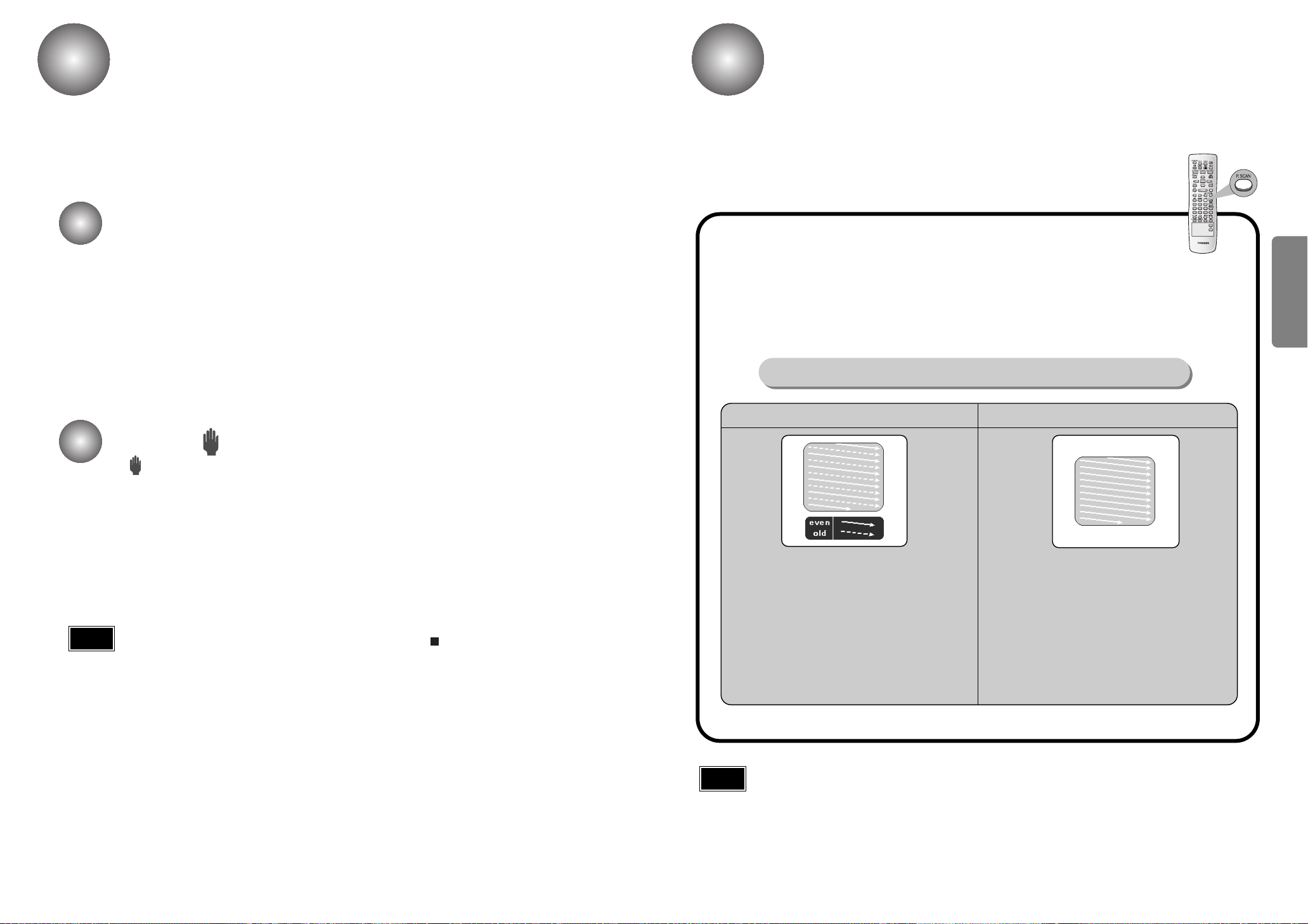
P.SCAN(Progressive Scan) Function
Your DVD player is capable of playing DVD, VCD, and CD discs.
User instructions may vary depending on the type of disc. Read the instructions
carefully before use.
TV Broadcast System
• This device is designed to work with the NTSC video format.
• To change the TV broadcast system to be output, press the ZOOM button while the
power is turned off. The selection will switch between NTSC and PAL each time
you press the button.
• For normal playback, the video format a DVD disc is recorded in must coincide
with your TV's video format.
About the symbol display
Unlike a regular Interlace Scan in which two fields of picture information are alternated to
create the entire picture (odd scan lines, then even scan lines), Progressive Scan uses
one field of information (all lines displayed in one pass) to create a clear and detailed
picture without visible scan lines.
While the player is in the Stop mode, hold the P.SCAN button down for
longer than 1 second.
The selection switches back and forth between "P.SCAN" and "I.SCAN" each time the
•
button is held down for a minimum of 1 second.
The previous mode is indicated in the display first, followed by the selected mode in about
•
a second.
What is Progressive (or Non-Interlaced) Scanning?
Interlaced Scan (1 FRAME = 2 FIELDS)
Progressive Scan (FULL FRAME)
CONNECTIONS
• “ ” may appear on the TV screen during operation.
This icon means the function explained in this owner’s manual is not available on
that specific DVD video disc.
Note
When the power is not turned on, press down the STOP ( ) button on the main unit for
•
over 5 seconds.
The product will be initialized to its optimum state.
Some operational features such as the Speaker mode, Test tone, Volume, etc. will not
•
be displayed on the TV screen.
In interlaced-scan video, a frame consists of two
interlaced fields (odd and even), where each field
contains every other horizontal line in the frame.
The odd field of alternating lines is displayed first, and
then the even field is displayed to fill in the alternating
gaps left by the odd field to form a single frame.
One frame, displayed every 1/30th of a second, contains
two interfaced fields, thus a total of 60 fields are
displayed every 1/60th of a second each.
The interlaced scanning method is intended for capturing
a still object.
Note
This function works only on TVs equipped with component video inputs (Y, Pr, Pb) that support Progressive
•
Video. (It does not work on TVs with conventional component inputs, i.e., non-progressive scan TVs.)
Depending on the brand and model of your TV, this function may not work.
•
The progressive scanning method scans one full frame of
video consecutively down the screen, line by line.
As opposed to the interlaced scanning process by which a
video image is drawn in a series of passes, you get an
entire image drawn at one time.
The progressive scanning method is desirable for dealing
with moving objects. A camera that has the ability to
capture moving objects is called a "full frame shutter
camera".
13
14

DVD Playback
V I D E O
1/2
1/8
0:13:25
OFF
1/1
1 ENG
D
6 CH
1/3
0:12:53
STER.
Using the On-Screen Display
1
Press the OPEN/CLOSE( ) button
to open the disc tray.
2
Insert a disc.
Place a disc gently into the tray with the
•
disc’s label facing up.
3
Press the OPEN/CLOSE( ) button
again to close the disc tray.
Playback starts automatically.
•
The general playback status can be displayed on the TV screen. Some items can be changed on the menu.
1
Press the DISPLAY button
during playback.
Items
Title Number
Chapter Number
Time search
Audio language
and Digital Audio
Output mode
Subtitle language
Angle
Press the UP/DOWN (▲ / ▼)
to select an item.
The selected item will be
•
highlighted.
Function (Press ▲ / ▼ to select desired item)
Displays the current title number and total number of
available titles, and skips to a desired title number.
Displays the current chapter number and total number of
available chapters, and skips to a desired chapter number.
Displays the elapsed playing time, and
searches a point identified by its elapsed time.
Displays the current audio soundtrack language,
encoding method and channel number, and
any changes you make to the setting.
Displays the current subtitles language, and
any changes you make to the setting.
Displays the current angle number and total number of
angles, and any changes you make to the angle number.
2
3
Press theLEFT/RIGHT( / )
to change the setting of an item.
The number buttons can be
•
also be used for setting
numbers (e.g., title number).
For some functions, press
ENTER to execute the setting.
Selection Method
/ , or
▲
Numbers, ENTER
/ , or
▲
Numbers, ENTER
Numbers, ENTER
▲ / ▼
▲ / ▼
▲ / ▼
▲
▲
▲
▲
OPERATION
Pausing Playback
Press the PLAY/PAUSE ( ) button during
playback.
To resume, press the PLAY/PAUSE ( )
•
button again.
Note
Depending on the disc, the initial disc
•
information screen may look different
from disc to disc.
15
Stopping Playback
Press the STOP ( ) button during playback.
During playback, when the STOP ( )button is
•
pressed, the position is stored in the memory, press
play to continue is shown on the display.
When the PLAY/PAUSE ( ) button is pressed
subsequently , playback resumes from the position at
which it was stopped.
If the STOP ( ) button is pressed a second time, the
•
resume play memory function is canceled, and STOP is
shown on the display. When the PLAY/PAUSE ( )
button is pressed, playback starts from the beginning.
Repeat
Items
Track Number
Time
Audio Channel
Repeat
Displays the repeat mode, –, title, chapter, A-B or OFF.
Function (Press ▲ / ▼ to select desired item)
Displays the current track number, total number of tracks
and PBC On mode, and skips to the desired track number.
Displays the elapsed playing time (Display only)
Displays the audio channel, and
changes you make to the audio channel.
Displays the repeat mode, –, title, chapter, A-B or OFF.
Selection Method
Numbers, ENTER
▲ / ▼
▲ / ▼ ,or
–
▲ / ▼
▲ / ▼
16
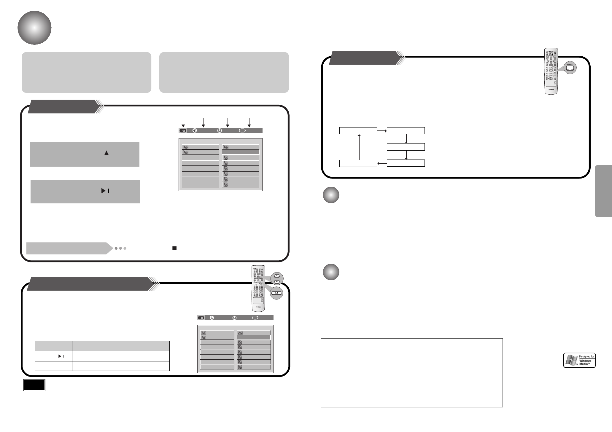
MP3/WMA CD Playback
TRACK1.MP3 1
TRACK2.MP3 2
TRACK3.MP3 3
TRACK4.MP3 4
TRACK5.MP3 5
TRACK6.MP3 6
TRACK7.MP3 7
TRACK
ROOT
TRAC 0
001/018 0:03:01 DISC
12 3 4
¢
REPEAT:RANDOM REPEAT:TRACK
REPEAT : DIR
REPEAT : DISC
REPEAT : OFF
TRACK1.MP3 1
TRACK2.MP3 2
TRACK3.MP3 3
TRACK4.MP3 4
TRACK5.MP3 5
TRACK6.MP3 6
TRACK7.MP3 7
TRACK
ROOT
TRAC 0
001/018 0:03:01 DISC
¢
You can play MP3/WMA files that have been recorded on a CD-R or CD-ROM on the DVD video player.
What is MP3? MP3 is an abbreviation of Motion Picture
Experts Group (or MPEG) Audio Layer 3. MP3 is simply a
file format with a data compression ratio of 1:10 (128 Kbps*).
That means,by using MP3 format, one CD-R or CD-RW can
contain 10 times as much data volume as a regular CD.
What is WMA? WMA (Windows Media Audio) is a file
format, created by Microsoft, that offers a higher compression
rate and just as good sound quality as MP3. Typical MP3 files
are about one-tenth the size of the original, whereas WMA
files are about half the size of standard MP3.
Starting Playback
It is recommended you turn on your TV when playing
•
back an MP3/WMA CD.
1
Press the OPEN/CLOSE( ) button
to load a disc.
2
Press the PLAY/PAUSE( ) button.
After detecting the disc, playback starts.
•
The on-screen bar and the contents
•
recorded on the MP3/WMA CD will be
shown on the TV if it is turned on.
To stop during playback
Press the STOP ( ) button.
1. Disc Type
2. Current track (file) and total number of the
tracks on the disc
3. Elapsed playing time and the total playing
time of the current track
4. Repeat mode indicator
Repeating Playback
On an MP3 disc, Repeat A↔B cannot be used. You can enjoy only repeat play.
Press the REPEAT button.
The indication corresponding to the selected
mode appears on the TV screen.
Each time you press the button, repeat
•
mode changes as follows:
REPEAT : RANDOM
•
: All tracks recorded on the disc will be played once in random
order.
REPEAT : TRACK
•
: Current track will be repeated.
REPEAT:DIR
•
: Tracks in the current directory will be repeated.
REPEAT : DISC
•
: All tracks on the disc will be repeated.
REPEAT OFF
•
: Repeat play is canceled.(Normal play is resumed.)
Playable files
MP3/WMA disc compatibility with this player is limited as follows:
Playable discs: CD-ROM, CD-R (650MB / 74 min. only)
•
Sampling Frequency: 44.1 kHz only
•
Bit rate: WMA: 48 kbps - 192 kbps (CBR)
•
CD physical format: Mode 1, Mode 2 XA Form 1
•
•
File system: ISO9660 Level 1, 2 or Joliet
CD-RW is not recommendable.
MP3: 32 kbps - 320 kbps (CBR)
File name: A file name should be in alphabet and numerals
•
Total number of folders: Less than 256
•
•
Total number of files: Less than 1000
•
WMA codec version: V7 or V8 (Stereo sound only)
only and must incorporate “MP3” or “WMA”
extension. e.g.”********.MP3”, “********.WMA”
OPERATION
Using the On-Screen Display
Turn on your TV when playing back an MP3/WMA disc.
When the loaded the MP3/WMA disc is recognized, the following
on-screen display appears on the TV screen.
(The contents of this on-screen display vary according to the disc — the
way the MP3 tracks were recorded on the disc.)
In stop mode, then select as follows :
Note
17
Button To do
ENTER, Start playback or go into a directory.
▲ / ▼
Depending on the recording mode, some MP3/WMA CDs cannot be played.
•
To select a track or directory in STOP mode
CD-R/RW playback compatibility
Your DVD player can also play CD-R and CD-RW discs
•
recorded in digital audio format. When recording your own
CD-R or CD-RW discs, make sure that the recording
session is properly terminated, or they will not be
playable.
(Depending on disc properties and recording quality,
some CD-R/RW may not be playable.)
This DVD video player requires discs/recordings to meet certain technical standards in
order to achieve optimal playback quality. Pre-recorded DVDs are automatically set to
these standards. There are many different types of recordable disc formats (including
CD-R containing MP3/WMA files). Given the fact that technology in this area is still
maturing.
Toshiba cannot guarantee that all genre of recordable discs will produce optimal
playback quality.
The technical criteria set out in this owner’s manual are meant as a guide only.
Customers should also not that permission is required in order to download MP3/WMA
files and music from the internet. Toshiba has no right to grant such permission.
Permission should always be sought from the copyright owner.
CD-RW has a lower reflection rate than CD-R media and
•
consequently it will take a longer to read CD-R discs.
CD-RW discs recorded at high speed tend to be difficult
•
for the DVD player to read. If the recording speed for the
CD-RW disc is not predetermined, write it at low speed.
Microsoft, Windows Media,
and the Windows Logo are
trademarks or registered
trademarks of Microsoft
Corporation in both the
United States and other
countries.
18

Forward/Reverse Searching
SF 1/4
SF 1/8
SF 1/2
SR 1/2
SR 1/4
SR 1/8
PLAY
2 X
4 X
8 X
32 X
FR
FR
FR
FR
PLAY
2 X
4 X
8 X
32 X
FF
FF
FF
FF
PLAY
TITLE 01/10 CHAPTER 001/017
TITLE 01/10 CHAPTER 003/017
CHAPTER ELAPSED
CHAPTER REMAIN
TITLE REMAIN
TITLE ELAPSED
TRACK ELAPSED
TRACK REMAIN
TOTAL ELAPSED
TOTAL REMAIN
SF 1/4
SF 1/6
SF 1/2
PLAY
During playback, you can search quickly through a chapter or track for a specific scene
or tune.
Slow Playback/Checking the
Remaining Time
Multi-Speed Playback
Press the and button.
▲
Each time the button is pressed
▲
▲
▲
▲
▲
Skipping through a Chapter
▲
Press the and button.
▲
▲
▲
▲
▲
Each time the button is pressed
Playing Slowly
Press the SLOW button.
Each time the SLOW button is pressed
Note
Checking the Remaining Time
Slow motion playback in reverse is not applicable for Video CD.
•
OPERATION
Each time the button is pressed during playback, it moves to the next
•
or previous chapter and plays it.
Press the STEP button.
19
Playing Frame by Frame
The picture moves forward one frame
•
each time the button is pressed.
Note
No sound is heard during
•
high-speed playback, slow
playback, and step motion.
Press the REMAIN button.
For checking the total and remaining time of a
•
title or chapter being played.
Each time the REMAIN button is pressed
VCD 2.0 with PBC is OFF
20

Repeat Playback
A TO B SET A
A TO B SET B
A TO B CANCELLED
Repeat playback allows you to repeat a chapter, title, or track.
Disc Menu/Top Menu Function
Playing Repeatedly
Press the REPEAT button.
Each time the REPEAT button is pressed
Note
Repeat playback operation is not possible with version 2.0 VCD discs if PBC is turned on.
•
To operate this feature, press the MENU button, and then select "PBC OFF".
Using the Disc Menu
You can use the menus for the audio language,
subtitle language, profile, etc. DVD menu contents
differ from disc to disc.
1
Press the MENU(DIGEST)
button during playback.
The Menu Screen appears.
•
When playing VCD version
•
2.0, you can operate it using
PBC On/Off function.
PBC (Playback Control) Function
When playing a VCD (version 2.0) with PBC function, you can view special scenes or menus.
Set PBC (Playback Control) to On or Off
On: Video CDs with PBC are played back according to the PBC.
Off: Video CDs with PBC are played back in the same way Audio CDs.
Use the UP/DOWN (▲ / ▼) or
LEFT/RIGHT( / ) button to
access the different features.
2
▲
▲
3
Press the ENTER button.
The selected item will play.
•
OPERATION
A↔B Repeat Playback
Press the REPEAT A↔B button at the
1
beginning (A) of the segment you want to
review.
Press the REPEAT A
2
the end (B) of the segment you want to
review.
The segment will begin repeating.
21
•
To return to normal playback
Press the REPEAT A↔B button again.
↔B button again at
Using the Top Menu
Press the TOP MENU button.
If the current title has a menu, the menu will appear on
•
the screen. Otherwise, the disc menu may appear.
The menu can list camera angles, spoken languages,
•
subtitle options, and chapters for the title.
To remove the top menu
Press the TOP MENU again.
22

Selecting the Audio Language/Subtitle Language
X 1.5 X 2 X 3 X 2 X 1.5 OFF
Zoom/Angle Functions
Selecting the Audio Language
Press the AUDIO button.
Depending on the number of languages recorded on a
•
DVD disc, a different audio language (ENGLISH,
SPANISH, FRENCH, etc.) is selected each time the
button is pressed.
Note
Depending on the disc, DTS or DOLBY PRO LOGIC can be selected.
•
Selecting the Subtitle Language
Press the SUBTITLE button.
To enlarge an image
This feature allows you to enlarge a particular area of the
•
displayed image.
During DVD playback, if you press the ZOOM(SILD SHOW)
•
button followed by the ENTER button, the selection switches
back and forth as follows.
To move to the area you want to zoom in on, press the
•
▲
/ / ▲ / ▼ button.
▲
Note
Only 2X zoom operation is possible during VCD playback.
•
Selecting the desired Screen Angle
X
OPERATION
Depending on the number of languages recorded
•
on a DVD disc, a different subtitle language
(ENGLISH, SPANISH, FRENCH etc.) is selected
each time the button is pressed.
To make the subtitles disappear, select "OFF".
•
Note
If this symbol “ ” appears on the TV screen while buttons are being
•
operated, that operation is not possible with that particular disc.
Depending on the disc, the audio or subtitle language function may not work.
•
23
SUBTITLE 01/05 : ENGLISH
SUBTITLE 02/05 : CHINESE
SUBTITLE 03/05 : THAI
SUBTITLE 04/05 : KOREAN
SUBTITLE 05/05 : UNKNOWN
SUBTITLE OFF
This feature allows you to view the same scene in different angles.
•
Press the ANGLE button.
This function only works with discs on which multiple angles have been recorded.
•
During playback, press the ANGLE button to select the desired angle: 3/3, 1/3, 2/3, 3/3
•
normal, in that order.
3/3
1/3
2/3
3/3
24

JPEG File Playback
Images captured with a digital camera or camcorder, or JPEG files on a
PC can be stored on a CD and then played back with this DVD player.
Slide Show Function
1
Place the JPEG disc on the disc tray.
Playback starts automatically.
•
Each image is shown for 5 seconds
•
before another image is displayed.
2
Press SLIDE SHOW(ZOOM) button.
Each time the button is pressed, the image makes the
•
transition as follows:
From top to bottom
From bottom to top
Retangular shape in the center
Vertical curtain shape
Digest Function
You can view 9 JPEG images on the TV screen.
•
1
Press DIGEST(MENU) button during
playback.
JEPG files will be shown in 9 windows.• The selected image is played for 5 seconds
•
• To view the previous or next image with 9 windows, select
▲
▲
▲
or button on TV screen.
▲
Press Cursor , , ▲ ,▼ buttons to select the
desired image and then press ENTER button.
before moving to the next image.
2
▲
▲
OPERATION
Each time a new image is displayed,
one of the slide modes (1~11) will
▲
Press , to skip to the next slide.
▲
▲
▲
automatically be applied.
Cancels the slide mode.
Rotate/Flip Function
▲
Press Cursor
▲
,,▲ ,
▼
buttons during playback.
• Each time the button is pressed, the slide moves backward or forward.
button: Flip Vertically
CD-R JPEG Discs
Only files with the ".jpg" and ".JPG" extensions can be played.
•
Only CD-R discs with JPEG files in ISO 9660 or Joliet format can be played.
•
JPEG file names should be 8 characters or less in length and contain no blank spaces or special characters (. / = +).
•
When playing a Kodak/Fuji Picture CD, only the JPEG files in the picture folder can be played.
•
Picture discs other than Kodak/Fuji Picture CDs may take longer to start playing or may not play at all.
•
Some files may not display their own entire image depending on the size.
•
Original Image
button: Rotate 90°
Counterclockwise
button: Flip Horizontally
25 26
button: Rotate 90° Clockwise

Program Playback
Program allows you to store your favourite tracks for a particular disc in the player memory.
To Program Tracks in a particular order
12
To delete the entire Program
Press the PROGRAM button to twice when in the stop mode.
•
Insert the disc and close the tray.
This function can be used only with CDs, and
•
you can program up to 99 tracks.
V I D E O
34
Press the NUMBERS (0~9) button to select the
desired track number and then press the
ENTER button.
The selected track is programmed.
•
To select another track, repeat Step 3.
•
PROGRAM P01:03
Press the PROGRAM button while in the
Stop mode.
The following will be displayed on the TV screen.
•
PROGRAM P00:00
To play the programmed track, press the
PLAY ( ) button.
When you have entered a wrong number
Press the NUMBERS (0~9) button to select the track you do not want to program and
•
then press the CLEAR button.
OPERATION
27
Note
If you open the tray, all programmed tracks will be cleared.
•
28

Setup Functions
-- GENERAL PAGE --
TV DISPLAY
OSD LANG
BLACK LEVEL
MAIN PAGE
DRC
OFF
ON
GENERAL SETUP
-- GENERAL PAGE --
TV DISPLAY
OSD LANG
BLACK LEVEL
MAIN PAGE
DRC
OFF
ON
GENERAL SETUP
-- GENERAL PAGE --
ON
BLACK LEVEL ON/OFF
TV DISPLAY
DRC
OSD LANG
BLACK LEVEL
MAIN PAGE
OFF
-- AUDIO SETUP --
DRC
DYNAMIC RANGE COMPRESSION
MAIN PAGE
FULL
6/8
4/8
2/8
OFF
You can install your own Personal Preferences.
Initial Settings General Operation
1
Press the SETUP button while
in Stop mode.
• The setup menu appears. • While the desired item is
SETUP MENU -- MAIN PAGE
GENERAL SETUP
PREFERENCES
EXIT SETUP
GENERAL SETUP
Press the UP/DOWN ( ▲ / ▼ )
to select the desired item.
displayed, press the ENTER
button.
GENERAL SETUP
2
SETUP MENU -- MAIN PAGE
GENERAL SETUP
PREFERENCES
EXIT SETUP
3
Press the UP/DOWN ( ▲ / ▼ )
to select the desired item.
-- GENERAL PAGE --
TV DISPLAY
OSD LANG
BLACK LEVEL
DRC
MAIN PAGE
GENERAL SETUP
ON
OFF
Adjusting the TV Aspect Ratio (Screen Size)
The horizontal to vertical screen size ratio of conventional TVs is 4:3, while that of wide screen and high
definition TVs is 16:9. This ratio is called the aspect ratio. When playing DVDs recorded in different screen
size, you should adjust the aspect ratio to fit your TV or monitor.
✱ For a standard TV, select either "4:3LB" or "4:3PS" option according to
personal preference. Select "16:9" if you have a wide screen TV.
: Select this to view a 16:9 picture in the
full-screen mode on your wide screen TV.
•You can enjoy the wide screen aspect.
: Select this to play a 16:9 picture in the
letter box mode on a conventional TV.
•Black bars will appear at the top and bottom of the
screen.
: Select this to play a 16:9 picture in the pan
& scan mode on a conventional TV.
•You can see the central portion of the screen only
(with the sides of the 16:9 picture cut off).
TV DISPLAY
OSD LANG
BLACK LEVEL
DRC
MAIN PAGE
GENERAL SETUP
Note
WIDE
-- GENERAL PAGE --
WIDE
4:3LB
4:3PS
4:3LB
(4:3 Letterbox)
4:3PS
(4:3 Pan&Scan)
• If a DVD is in the 4:3 ratio, you cannot view it in wide screen.
• Since DVD discs are recorded in various image formats, they will look different
depending on the software, the type of TV, and the TV aspect ratio setting.
29
4
While the desired item is
displayed, press , then
UP/DOWN ( ▲ / ▼ ) to select
the desired setting.
• The screen will display the
current setting for the selected
item, as well as alternate
setting(s).
▲
5
Press ENTER to confirm your
selection.
• Some items require additional
steps.
6
Press SETUP, RETURN to
exit the setup menu.
If you select "MAIN PAGE", you will be return to
the Setup screen.
OSD Language
Select a language for the setup menu.
This is the menu you see when you press SETUP.
Note
This function may not work depending on the type of
•
disc inserted.
Black Level
To select the black level of playback pictures.
Set your preference and monitor’s ability.
• On: Expanded grey scale. (0 IRE cut off)
• Off: Standard grey scale. (7.5 IRE cut off)
DRC (Dynamic Range Control)
With the DVD format, you can hear a program’s soundtrack in the most
accurate and realistic presentation possible, thanks to digital audio
technology. However, you may wish to compress the dynamic range of the
audio output (the difference between the loudest sounds and the quietest
ones). Then, you may listen to a movie at a lower volume without losing
clarity of sound. Set DRC to On for this effect.
Note
This function works only in Dolby Digital mode.
•
-- GENERAL PAGE --
TV DISPLAY
OSD LANG
BLACK LEVEL
DRC
MAIN PAGE
SET OSD LANGUAGE
ENGLISH
FRENCH
SPANISH
SETUP
30

-- PREFERENCES PAGE --
AUDIO
SUBTITLE
DISC MENU
PARENTAL
PASSWORD
1G
2
3 PG
4 PG 13
5
6 PG-R
7 NC-17
8 ADULT
NO_PARENTAL
SET PARENTAL CONTROL
MAIN PAGE
-- PREFERENCES PAGE --
AUDIO
SUBTITLE
DISC MENU
PARENTAL
PASSWORD
1G
2
3 PG
4 PG 13
5
6 PG-R
7 NC-17
8 ADULT
NO_PARENTAL
SET PARENTAL CONTROL
MAIN PAGE
PASSWORD VERIFY PAGE
INPUT PASSWORD
PLEASE ENTER PASSWORD
-- PREFERENCES PAGE --
AUDIO
SUBTITLE
DISC MENU
PARENTAL
PASSWORD
ENGLISH
KOREAN
FRENCH
SPANISH
CHINESE
JAPANESE
OTHERS
PREFERREO MENU LANGUAGE
MAIN PAGE
-- PREFERENCES PAGE --
AUDIO
SUBTITLE
DISC MENU
PARENTAL
PASSWORD
ENGLISH
KOREAN
FRENCH
SPANISH
CHINESE
JAPANESE
OTHERS
PREFERREO MENU LANGUAGE
MAIN PAGE
Setup Functions (Continue)
Disc Language
1
Press the SETUP button while
in Stop mode.
Press the UP/DOWN ( ▲ / ▼ )
to select the desired item.
2
• The setup menu appears. • While the desired item is
display, press the ENTER
button.
SETUP MENU -- MAIN PAGE
GENERAL SETUP
GENERAL SETUP
PREFERENCES
EXIT SETUP
SETUP MENU -- MAIN PAGE
PREFERENCS
GENERAL SETUP
PREFERENCES
EXIT SETUP
3
Press the UP/DOWN ( ▲ / ▼ )
to select the desired item.
-- PREFERENCES PAGE --
AUDIO
SUBTITLE
DISC MENU
PARENTAL
PASSWORD
MAIN PAGE
PREFERREO MENU LANGUAGE
ENGLISH
KOREAN
FRENCH
SPANISH
CHINESE
JAPANESE
OTHERS
-- PREFERENCES PAGE --
AUDIO
SUBTITLE
DISC MENU
PARENTAL
PASSWORD
MAIN PAGE
PREFERREO MENU LANGUAGE
ENGLISH
KOREAN
FRENCH
SPANISH
CHINESE
JAPANESE
OTHERS
• Select a language for the disc’s Menu, Audio and Subtitle.
• Original : The original language set for the disc is selected.
• Other : To select another language, press number buttons to enter the
corresponding 4-digit number according to the language code list on
page 44. If you enter the wrong language code, press CLEAR.
Parental Control
Movies on DVDs may contain scenes not suitable for children. Therefore, discs may contain Parental
Control information that applies to the complete disc or to certain scenes on the disc. These scenes are
rated from 1 to 8, and alternatively, more suitable scenes are available for selection on some discs. Ratings
are country dependent. The Parental Control feature allows you to prevent discs from being played by your
children or to have certain discs played with alternative scenes.
1. Select “PARENTAL” on the Setup menu using the
buttons.
2. While “PARENTAL” is selected, press .
▲
UP/DOWN (▲ / ▼)
SETUP
While the desired item is
displayed, press , then
UP/DOWN ( ▲ / ▼ ) to select
the desired setting.
• The screen will display the
current setting for the selected
item, as well as alternate
setting(s).
31 32
4
▲
5
Press ENTER to confirm your
selection.
• Some items require additional
steps.
6
Press SETUP, RETURN to
exit the setup menu.
If you select "MAIN PAGE", you will be return to
the Setup screen.
Note
3. Use the
UP/DOWN (▲ / ▼)
buttons to select a parental control rating
(from 1 to 8) and then press the ENTER button.
Ratings 1 to 8: Some discs contain scenes not suitable for children. If you set a
rating for the player, all disc scenes with the same rating or lower
will be played. Higher rated scenes will not be played unless an
alternative scene is available on the disc. The alternative must
have the same rating or a lower one. If no suitable alternative is
found, playback will stop. You must enter the 4-digit password or
change the rating level in order to play the disc.
4. Input a password and then press the ENTER button.
The player's password is set to "
•
There are up to 8 rating levels on a disc.
•
If LEVEL 6 is selected, a disc which contains rating LEVEL 7 and above cannot be played.
•
If you select NEW PASSWORD, the screen changes and enables you to enter the new
•
password.
When the rating level password has been forgotten
While the player is in the stop mode, hold the Stop ( ) button down on the main unit for
more than 5 seconds.
"INITIAL" appears on the display and all default settings will return to Factory Preset.
•
Press the On/Standby ( ) button.
•
7890
" by default.

DIGITAL
L
LS RS
C
LFT
R
F SP SMALL
C SP SMALL
R SP SMALL
SW SP USE
C DLY MS
R DLY MS
DIGITAL
L
LS RS
C
LFT
R
DIGITAL
L
LS RS
C
LFT
R
DIGITAL
L
LS RS
C
LFT
R
DIGITAL
L
LS RS
C
LFT
R
DIGITAL
L
LS RS
C
LFT
R
C SP NONE
R SP NONE
DIGITAL
L
LS RS
C
LFT
R
DIGITAL
L
LS RS
C
LFT
R
Speaker Setup
Setting up Speaker Mode and Delay Time
1
Press the SPK MODE button.
Each time the button is pressed, a different mode selection is
•
displayed on the front panel display as shown below.
S
p
Front speaker: Small
e
a
k
Center speaker: Small
e
r
M
o
Rear speaker: Small
d
e
Subwoofer: Use
Delay
Center Speaker Delay Time
Time
Rear Speaker Delay Time
Press the LEFT/RIGHT ( / ) button to
select the desired item.
Center speaker: Not Used
Rear speaker: Not Used
Setting up Delay Time from 00~05ms
Setting up Delay Time from 00~15ms
2
▲
▲
Setting up the Speaker Delay Time
When 5.1CH Surround Sound is played, you can enjoy the best sound if the distance between you and each speaker is the
same. Since the sounds arrive at the listening position at different times depending on the placement of speakers, you can
adjust this difference by adding a delay effect to the sound of the Center Speaker and Surround Speakers.
Setting CENTER SPEAKER
•
If the distance of Dc is equal to or longer than
the distance of Df in the figure, set the mode
as 0ms. Otherwise, change the setting
according to the table.
Distance between Df and Dc Delay Time
20 Inches
40 Inches
5 feet
6 feet 6.6 inches
Setting REAR (SURROUND) SPEAKERS
•
1.3 ms
2.6 ms
3.9 ms
5.3 ms
If the distance of Df is equal to the distance of
Ds in the figure, set the mode as 0ms.
Otherwise, change the setting according to the
table.
Distance between Ds and Dc
6 feet 6.6 inches
13 feet 3.3 inches
20 feet
Delay Time
5.3 ms
10.6 ms
15.9 ms
It is desirable to place all speakers within this circle.
Df: The distance from FRONT SPEAKER
Dc: The distance from CENTER SPEAKER
Ds: The distance from SURROUND SPEAKER
Ideal CENTER SPEAKER placement
Ideal SURROUND
SPEAKER placement
SETUP
SMALL: When this setting is selected, low frequencies of below 200 Hz are assigned to
•
Note
USE: Select when using speakers.
•
NONE: Select this when no speakers are installed.
•
The display changes depending on the current audio output mode (PRO LOGIC II, STEREO, etc.).
•
the subwoofer only.
Note
Speaker delay time setting is a professional sound volume adjustment method for audio
•
enthusiast. For home use, refer to "Setting up the Ideal Speaker Positions" below to
install speakers in appropriate locations.
33 34

To set up Speaker Balance
L
LS
RS
C
LFE
R
You can set the sound level of the diesired channel.
Creating Realistic Sound Fields
To set up Speaker Balance
1
Press the SOUND EDIT button. Each time the
button is pressed, the selection switches as
shown below.
Example: 5.1CH Sound Setup
PRO LOGIC
D I G I T A L
LINEAR PCM
LCR
LFE
LS
SRS
OFF, range of – 6 ~ 0
Front Speakers: L level, R level
PRO LOGIC
D I G I T A L
LINEAR PCM
LCR
LFE
LS
SRS
OFF, range of – 6 ~ 0
Rear Speakers: L level, R level
PRO LOGIC
D I G I T A L
LINEAR PCM
LCR
LFE
LS
SRS
range of – 6 ~ – 00 ~ +6
Center Speaker
PRO LOGIC
D I G I T A L
LINEAR PCM
LCR
LFE
LS
SRS
range of – 6 ~ – 00 ~ +6
Rear Speakers
PRO LOGIC
D I G I T A L
LINEAR PCM
LCR
LFE
LS
SRS
range of – 6 ~ – 00 ~ +6
Subwoofer Speaker
Note
The display changes depending on the current audio output mode ( PRO LOGIC II,
•
STEREO, etc.).
Test Tone FUNCTION
Press the TEST TONE button on the remote control.
This function allows you can easily adjust the sound balance
•
of the speakers from the listener's position.
The test signal will be sent to the Left Front ➞ Center ➞
•
Right Front ➞ Right Rear ➞ Left Rear ➞ LFE in that order.
Use the LEFT/RIGHT ( / ) button to raise
or lower the output level of the chosen
speaker(s).
2
▲
▲
You can use the following surround modes to reproduce a realistic sound field.
• Digital Multichannel Surround —Dolby Digital and DTS Digital Surround
• Dolby Pro Logic II
Dolby Digital and DTS Digital Surround
To enjoy surround effectively, all the speakers need to be connected and activated.
Dolby Digital
Used to reproduce multichannel sound tracks of the software encoded with Dolby Digital ( ).
Dolby Digital encoding method (discrete 5.1 channel digital audio format)records and digitally compresses the left front
channel,right front channel,center channel, left rear channel, right rear channel and LFE channel signals (total 6 channels, but LFE
channel is counted as 0.1 channel).
In addition,Dolby Digital enables stereo rear sounds, and sets the cutoff frequency of the rear treble at 20 kHz,compared to 7 kHz
for Dolby Pro Logic. These facts result in better sound quality than Dolby Pro Logic.
When the system detects Dolby Digital signals,the DOLBY DIGITAL indicator lights up on the display.
DTS Digital Surround
Used to reproduce multichannel sound tracks for software encoded with DTS Digital Surround ( ).
DTS Digital Surround is another discrete 5.1 channel digital audio format available on CD, LD and DVD software.
Compared to Dolby Digital, audio compression rate is relatively low.
This fact allows DTS Digital Surround format to add breadth and depth to the reproduced sounds. As a result, DTS Digital
Surround features natural, solid and clear sound.
When the system detects DTS Digital Surround signals, the DTS indicator lights up on the display.
SETUP
Dolby Pro Logic II
• Dolby Pro-Logic II is a new multi-channel playback format developed by Dolby Laboratories using feedback logic
steering technology and offering improvements over conventional Dolby Pro Logic circuits.
• Dolby Pro Logic II can be used to decode not only sources recorded in Dolby Surround ( ) but also
regular stereo sources into five channels (front left, front right, center, surround left and surround right) to achieve
surround sound.
• Whereas with conventional Dolby Pro Logic the surround channel playback frequency band was limited, Dolby Pro
Logic II offers a wider band range.
In addition, the surround channels were monaural (the surround left and right channels were the same) with previous
Dolby Pro Logic, but with Dolby Pro Logic II they are stereo.
* Sources recorded in Dolby Surround
These are sources in which three or more channels of surround have been recorded as two channels of signals
using Dolby Surround encoding technology.
Dolby Surround is used for the sound tracks of movies recorded on DVDs, LDs and video cassettes to be played on
stereo VCRs, as well as for the stereo broadcast signals of FM radio, TV, satellite broadcasts and cable TV.
Decoding these signals with Dolby Pro Logic makes it possible to achieve multi-channel surround playback.
The signals can also be played on ordinary stereo equipment, in which case they provide normal stereo sound.
To End the Speaker Setup
Press the TEST TONE button again.
•
Note
While in STEREO or PRO LOGIC mode, TEST TONE may operate
•
differently for VCDs or CDs.
When playing a DVD or CD, this will work only in STOP mode.
•
Manufactured under license from Dolby Laboratories. “Dolby,”
“Pro Logic,” and the double-D symbol are trademarks of Dolby
Laboratories. Confidential Unpublished Works. ©1992–1997
Dolby Laboratories, Inc. All rights reserved.
Manufactured under license from Digital Theater Systems, Inc.
US Pat. No. 5,451,942 and other world-wide patents issued
and pending. “DTS” and “DTS Digital Surround” are
trademarks of Digital Theater Systems, Inc. ©1996 Digital
Theater Systems, Inc. All rights reserved.
3635

PRO LOGIC
LR
LR
PRO LOGIC
LR
PRO LOGIC
PRO LOGIC
LR
PRO LOGIC
LR
LR
Dolby Pro Logic II decoder
Dolby Pro Logic II
Dolby Pro Logic II is a new format for playing multichannel audio signals that offers improvements over
conventional Dolby Pro Logic. It can be used to decode not only sources recorded in Dolby Surround, but
also regular stereo sources into five channels (front left/right, center and surround left/right). In addition,
various parameters can be set according to the type of source and the contents, so you can adjust the
sound field with greater precision.
1
Press the Function button on the front panel to select the desired function.
Select from FM ➞ AM ➞ DVD ➞ DIGITAL IN ➞ AUX 1 ➞ AUX 2.
•
23
Press the PL II button. Press the PL II MODE button.
Each time the PL II button is pressed.
•
Each time the PL II MODE button is pressed.
•
Pro Logic II Mode
Select one of the modes (“CINEMA”, “PRO LOGIC”, “MATRIX” or “MUSIC”).
The Music mode is recommended when listening to CDs or watching DVDs with
•
mostly musical content.
The Cinema mode is best when watching movies.
•
The Pro Logic mode offers the same surround processing as original Pro Logic
•
and is best used when the source contents are not of optimum quality.
The Matrix mode is useful for when the audio is mono.
•
Note
When playing a DVD encoded in two or more channels, DOLBY PRO LOGIC II
•
mode cannot be selected.
SETUP
PRO LOGIC II : Left, Center, Right,
Subwoofer and
Surround(Left, Right)
Channels
STEREO : Left, Right and Subwoofer Channels
3837

Listening to the Radio
Presetting the radio stations
Remote
Control
Unit
Main
Unit
Preset radio stations in the DVD receiver’s memory first (see “Presetting radio stations”
on the Right side).
1
Press the TUNER button.
The selection toggles back
•
and forth between "FM" and
"AM" each time the
Tuner(Band) button is
pressed.
1
Press the Function button to
select the desired band (FM,
AM).
Select a broadcast station.
Auto Station 1
Auto Station 2
Manual Station
When the or button is pressed, a preset
broadcast station is selected.
Hold in the or button. Automatic searching
begins, and then stops when a station is tuned in.
Press the
station. The frequency changes incrementally in either
direction each time the corresponding button is pressed.
Select a broadcast station.
2
or
button to tune to the chosen
2
You can preset 30 stations for FM and AM. Before tuning, make sure that you have turned
down the volume.
Example: Presetting FM 89.1 in the memory
1
Press the TUNER button and
select the FM band.
The selection toggles back and forth between “FM” and “AM”
•
each time the Tuner button is pressed.
LR
Select MANUAL by pressing
the STOP ( ) button on
the main unit.
MH
Z
LR
2
456
Press the PROGRAM button on
the remote control, FM1 will
flash. If you want to save 89.1 to
FM1, press Program again.
If you want to save 89.1 to another
preset location(FM2~FM15), press
Program to save it to that location.
▲
▲
or , then press
▲
▲
3
▲
Use the or
button to tune to 89.1
LR
To preset other stations,
follow steps 1~5 again.
▲
▲
▲
MH
Z
Auto Station 1
Auto Station 2
Manual Station
Press the Stop ( ) button to select the PRESET
mode. Then press the or button to select a
station stored in the preset. See the instructions on the
next page to preset stations.
Press the Stop ( ) button to select the MANUAL
mode on the front panel. Then hold in the or
button to make the unit begin automatically searching for
broadcast stations.
Press the Stop ( ) button to select the MANUAL mode
on the front panel. Press the or button to
tune to the desired station. The frequency changes
incrementally in either direction each time the
corresponding button is pressed.
PROGRAM
LR
MH
Z
To tune in a preset station
See the previous page.
LR
LR
PROGRAM
MH
Z
MH
Z
RADIO OPERATION
4039

Sleep Function
Cautions on Handling and Storing Discs
Small scratches on the disc may reduce sound and picture quality or cause breaks
in playback. Be especially careful not to scratch discs when handling them.
To set up Sleep
Press the SLEEP button.
Each time the button is pressed the selection
•
toggles as follows: SLEEP 10➔SLEEP 20
➔
SLEEP 30 ➔ SLEEP 60 ➔ SLEEP 90
➔
SLEEP 120 ➔ SLEEP 150 ➔ OFF.
To Review Sleep Setting
Press the SLEEP button.
•
The remaining time for the selected Sleep time is displayed on the front panel.
Pressing the button once again changes the Sleep time from the last setting.
•
Using Headphone Jack
Connect a stereo headphone plug (ø3.5mm) into the PHONES connector.
The speakers are automatically disconnected when you plug in the headphones (not supplied).
Note
When you use the headphones, keep the volume at a moderate level.
•
If you use the headphones continuously with high volume sound,
it may cause hearing damage.
What is the
Sleep function?
You can set the sleep time so that
the unit powers off automatically
after a preset period of time.
Handling discs
Handling and Storing Discs
When you get fingerprints or dirt on the
disc, clean it with a mild detergent diluted
in water and wipe with a soft cloth.
When cleaning, wipe gently from the inside to the
•
outside of the disc.
Note
Condensation may form if warm air comes into contact with cold parts inside the
•
player. When condensation forms inside the player, the player may not operate
correctly. If this occurs, remove the disc and let the player stand for 1 or 2 hours
with the power on.
Do not touch the playback side of the
disc. Hold the disc by the edges so that
fingerprints will not get on the surface.
Do not stick paper or tape on the disc.
Mute Function
Press MUTE to mute your unit.
You can mute your unit in order, for example, to answer the telephone,
“MUTE” indicator flashes in the display window.
Disc Storage
Do not keep in direct
sunlight
Caution
•
•
Keep in a cool
ventilated area
Keep in a clean
Protection jacket.
Store vertically.
Do not allow the discs to become contaminated with dirt.
Do not load cracked discs or discs that are scratched.
MISCELLANENOUS
4241

Troubleshooting
Language Code List
Check the following guide for the possible cause of a problem before contacting service.
Symptom Cause Correction
No power.
The power is on, but
the DVD receiver
does not work.
No picture.
No sound.
The playback
picture is poor.
The DVD receiver
does not start
playback.
The remote control
does not work
properly.
The power cord is disconnected.
•
No disc is inserted.
•
The TV is not set to receive DVD signal
•
output.
The video cable is not connected
•
securely.
The connected TV power is turned off.• Turn on the TV.
•
The equipment connected with the
•
audio cable is not set to receive DVD
signal output.
The audio cables are not connected
•
securely.
The power of the equipment connected
•
with the audio cable is turned off.
The Digital Audio Output is set to the
•
wrong position.
The disc is dirty.
•
No disc is inserted.
•
An unplayable disc is inserted.
•
The disc is placed upside down.
•
The disc is not placed within the guide.
•
The disc is dirty.
•
The Rating level is set.
•
The remote control is not pointed at the
•
remote sensor of the DVD receiver.
The remote control is too far from the
•
DVD receiver.
There is an obstacle in the path of the
•
remote control and the DVD receiver.
The batteries in the remote control are
•
exhausted.
Plug the power cord into the wall outlet
•
securely.
Insert a disc. (Check that the DVD or,
•
audio CD indicator in the display
window is lit.)
Select the appropriate video input mode
•
on the TV so the picture from the DVD
receiver appears on the TV screen.
Connect the video cable into the jacks
•
securely.
Select the correct input mode of the
•
audio receiver so you can listen to the
sound from the DVD receiver.
Connect the audio cable into the jacks
•
securely.
Turn on the equipment connected with
•
the audio cable.
Set the Digital Audio Output to the correct
•
position, then turn on the DVD receiver
again by pressing On/standby( ).
Clean the disc.
•
Insert a disc. (Check that the DVD, or audio
•
CD indicator in the DVD display is lit.)
Insert a playable disc. (Check the disc
•
type, color system and Regional code.)
Place the disc with the playback side
•
down.
Place the disc on the disc tray correctly
•
inside the guide.
Clean the disc.
•
Cancel the Rating function or change
•
the rating level.
Point the remote control at the remote
•
sensor of the DVD receiver.
Operate the remote control within about
•
23 ft (7 m).
Remove the obstacle.
•
Replace the batteries with new ones.
•
Enter the appropriate code number for the initial settings “Disc Audio”, “Disc Subtitle”
and/or “Disc Menu” (See page 32).
MISCELLANENOUS
43
44

Specifications Memo
G
E
N
E
R
A
L
T
U
F
N
M
E
R
T
U
A
N
M
E
R
VIDEO
INPUT
O
V
U
I
T
D
P
E
U
O
T
A
M
P
L
I
F
I
E
R
S
P
E
A
K
E
R
Power Requirement
Power Consumption
Weight
Dimensions (W x H x D)
Operating Temperature Range
Operating Humidity Range
Usable Sensitivity
S/N Ratio
Distortion
Usable Sensitivity
S/N Ratio
Distortion
Component Video
Composite Video
Component Video
S-VIDEO
Front speaker output
Center speaker output
Rear speaker output
Subwoofer speaker output
Frequency range
S/N Ratio
Channel separation
Input sensitivity
Speaker system
Impedance
Frequency range
Output sound pressure level
Rated input
Maximum input
Dimensions
Weights
(W x H x D)
AC 120V, 60Hz
120W
7.0Kg
360 x 76 x 367 mm
+5°C ~ +35°C
10% ~ 75%
10dB
55dB
0.3%
54dB
35dB
2%
Y:1.0Vp-p(75Ω load), Pr:0.70Vp-p(75Ω load)
Pb:0.70Vp-p(75Ω load)
1.0Vp-p(75Ω load)
Y:1.0Vp-p(75Ω load)
Pr:0.70Vp-p(75Ω load)
Pb:0.70Vp-p(75Ω load)
Luminance Signal: 1.0Vp-p(75Ω load)
Color Signal: 0.286Vp-p(75Ω load)
50W x 2(6Ω), Distortion 10%
50W(6Ω), Distortion 10%
50W(6Ω), Distortion 10%
70W(3Ω), Distortion 10%
20~25KHz
75dB
53dB
(AUX)500mV
5.1ch speaker system
Front/Center/Rear speaker
6Ω x 5
100Hz~18KHz
87dB/W/M
40W
80W
Front/Rear
Center
Front/Rear
Center
103 x 150 x 120 mm
197 x 103 x 120 mm
2.92 Kg
0.8 Kg
Subwoofer speaker
3Ω
40Hz~200Hz
86dB/W/M
70W
170W
210 x 365 x 342 mm
6.6 Kg
MISCELLANENOUS
4645

Limited Warranty DVD Video Player
Toshiba America Consumer Products, Inc. ("TACP") and Toshiba Hawaii, Inc. (THI") make the following limited
warranties to original consumers for DVD Players purchased and used in the United States. THESE LIMITED
WARRANTIES EXTEND TO THE ORIGINAL CONSUMER PURCHASER OR ANY PERSON RECEIVING THIS DVD
PLAYER AS A GIFT FROM THE ORIGINAL CONSUMER PURCHASER AND TO NO OTHER PURCHASER OR
TRANSFEREE.
PRODUCTS PURCHASED IN THE U.S.A. AND USED IN CANADAARE NOT COVERED BY THESE WARRANTIES.
PRODUCTS PURCHASED IN CANADA AND USED IN THE U.S.A. ARE NOT COVERED BY THESE WARRANTIES.
Limited One (1) Year Warranty®
TACP/THI warrants this DVD Player against defects in materials
or workmanship for a period of one (1) year after the date of the
original retail purchase. DURING THIS PERIOD TACP/THI WILL,
AT TACP/THI'S OPTION, REPAIR OR EXCHANGE A
DEFECTIVE DVD PLAYER WITH A NEW OR REFURBISHED
DVD PLAYER, AT TACP/ THI'S OPTION. DURING THE INITIAL
NINETY (90) DAYS, THIS REPAIR OR EXCHANGE WILL BE
WITHOUT CHARGE TO YOU, EXCEPT YOU MUST PAY FOR
ALL TRANSPORTATION AND INSURANCE CHARGES FOR
THE DVD PLAYER TO BE SHIPPED TO THE DESIGNATED
TACP/THI FACILITY. AFTER THE INITIAL NINETY (90) DAYS
AND FOR THE REMAINDER OF THE WARRANTY PERIOD, AN
ADDITIONAL HANDLING FEE WILL APPLY. YOU MUST
DELIVER THE ENTIRE DVD PLAYER AND ALL ACCESSORIES
(SUCH AS POWER CORDS, CABLES, AND THE UNIT'S
REMOTE CONTROL DEVICE) TO THE DESIGNATED TACP/THI
FACILITY, AS INSTRUCTED BY TACP/THI. TACP/THI IS NOT
RESPONSIBLE IF YOUR DVD PLAYER IS LOST OR DAMAGED
DURING SHIPMENT.
*Commercial Units
DVD Players sold and used for commercial purposes have a
limited ninety (90) day warranty.
Rental Units
The warranty period for rental units begins with the first rental or
thirty (30) days from the date of shipment to the rental firm,
whichever comes first.
Owner's Manual and Demographic Card
You should read this owner's manual thoroughly before operating
this DVD Player. You should complete and mail the enclosed
Demographic Card within ten days after you, or the person who
has given you this product as a gift, purchased this DVD Player.
This is one way to enable TACP/THI to provide you with better
customer service and improved products. Failure to return the
Demographic Card will not affect your rights under this warranty.
Your Responsibility
THE ABOVE LIMITED WARRANTIES ARE SUBJECT TO THE
FOLLOWING CONDITIONS:
(1) You must provide your bill of sale or other proof of purchase.
For rental firms, proof of first rental is also required.
(2) The limited warranties from TACP and THI are effective only if
the DVD Player is purchased and operated in the U.S.A. or
Puerto Rico.
(3) Labor service charges for installation, set up, and adjustment
of customer controls are not covered by these limited
warranties.
(4) These limited warranties extend only to defects in materials or
workmanship as limited above and do not extend to any DVD
Player or accessories which have been lost or discarded by
you, or to damage to any DVD Player or accessories caused
by misuse, accident, Acts of God (such as lightning), or to
fluctuations in electric power, improper installation, improper
maintenance or use in violation of instructions fumished by
TACP/THI; or to units which have been modified or which have
had the serial number removed, altered, defacted or rendered
illegible.
(5) Physically damaged DVD Players are not acceptable for repair
or exchange whether in or out of warranty and will be returned
as receiver.
How to Obtain Warranty Services
If, after following all of the operating instructions in this manual
and checking the "Troubleshooting" section, you find that service
is needed, call one of the following Customer Solutions Centers to
obtain further instructions. Have your proof of purchase and your
model and serial numbers available when you call.
For DVD Players purchased in the United States,
except Hawaii, call TACP, toll free at 1-866-583-7353.
For DVD Players purchased in Hawaii, call THI, at
808-591-9281.
LIMITATION OF IMPLIED WARRANTIES
ALL WARRANTIES IMPLIED BY THE LAW OF ANY STATE OF
THE U.S.A., INCLUDING THE IMPLIED WARRANTIES OF
MERCHANTABILITY AND FITNESS FOR A PARTICULAR
PURPOSE, ARE EXPRESSLY LIMITED TO THE DURATION OF
THE LIMITED WARRANTIES SET FORTH ABOVE.
LIMITATION OF WARRANTY
WITH THE EXCEPTION OF ANY WARRANTIES IMPLIED BY
THE LAW OF ANY STATE OF THE U.S.A. AS HEREBY
LIMITED, THE FOREGOING LIMITED WARRANTY IS
EXCLUSIVE AND IN LIEU OF ALL OTHER WARRANTIES,
GUARANTEES, AGREEMENTS AND SIMILAR OBLIGATIONS
OF TACP OR THI WITH RESPECT TO YOUR DVD PLAYER.
EXCLUSION OF DAMAGES
IN NO EVENT SHALL TACP OR THI BE LIABLE FOR
CONSEQUENTIAL OR INCIDENTAL DAMAGES.
No Change, Modification, or Extension
No person, agent, distributor, dealer or company is authorized to
change, modify or extend the terms of these limited warranties in
any manner whatsoever.
ATTENTION CANADIAN CONSUMERS:
Canadian consumers are reuqested to complete the special Canadian "Warranty Registration Form" enclosed, and forward this completed
from with a copy of bill of sale to TOSHIBA OF CANADA to "Register and Validate" their warranty. Product must be purchased from an
Authorized Canadian Dealer. Products purchased in the U.S.A. and used in Canada are not covered by these warranties.
Contact:Toshiba of Canada Limited
Consumer Electronics Group Consumer Electronics Group Consumer Electronics Group
191 McNabb Street 22171 Fraserwood Way 1643 North Service Road
Markham, Ontario L3R 8H2 Richmond, B.C. V6W 1J5 Droval, QC H9P 1J1
(905)-470-5400 (604)-303-2500 (514)-856-4100
IMPORTANT: PACKING AND SHIPPING INSTRUCTION
When you send the product to a Service Station, you must use the original carton box and packing material, then insert the original carton
box containing the unit into another carton using more packing material.
Time for Taking Action
The time within which action must be commenced to enforce any
obligation of TACP or THI arising under this limited warranty or
under any law of the United States or of any state thereof is
hereby limited to 90 days from the date you discovered, or should
have discovered, the defect. This limitation does not apply to
implied warranties arising under the law of any state of the U.S.A.
HOW STATE LAW RELATES TO WARRANTY
THIS WARRANTY GIVES YOUR SPECIVIC LEGAL RIGHTS,
AND YOU MAY ALSO HAVE OTHER RIGHTS WHICH MAY
VARY FROM STATE TO STATE IN THE U.S.A.
SOME STATES OF THE U.S.A. DO NOT ALLOW LIMITATIONS
ON HOW LONG AN IMPLIED WARRANTY LASTS, WHEN AN
ACTION MAY BE BROUGHT, OR THE EXCLUSING OR
LIMITATION OF INCIDENTAL OR CONSEQUENTIAL
DAMAGES, SO THE ABOVE LIMITATIONS OR EXCLUSIONS
MAY NOT APPLY TO YOU UNDER SUCH CIRCUMSTANCES.
MISCELLANENOUS
For additional updates, visit TACP's web site:
www.toshiba.com/tacp.
47 48
 Loading...