

Toshiba Satellite, Satellite PRO, Satellite PRO T230D, Satellite T230D Maintenance Manual

Toshiba Personal Computer
Satellite/Satellite PRO
Maintenance Manual
TOSHIBA CORPORATION
[CONFIDENTIAL]

Copyright
© 2010 by Toshiba Corporation. All rights reserved. Under the copyright laws, this manual
cannot be reproduced in any form without the prior written permission of Toshiba. No patent
liability is assumed with respect to the use of the information contained herein.
Toshiba Personal Computer STREAMLINE-M 10A SERIES MAINTENANCE MANUAL
Maintenance Manual
First edition April, 2010
Disclaimer
The information presented in this manual has been reviewed and validated for accuracy. The
included set of instructions and descriptions are accurate for the STREAMLINE-M 10A SERIES
MAINTENANCE MANUAL Series at the time of this manual's production. However,
succeeding computers and manuals are subject to change without notice. Therefore, Toshiba
assumes no liability for damages incurred directly or indirectly from errors, omissions, or
discrepancies between any succeeding product and this manual.
Trademarks
IBM is a registered trademark, and OS/2 and PS/2 are trademarks of IBM Corporation.
Microsoft, MS-DOS, Windows, DirectSound and DirectMusic are registered trademarks of
Microsoft Corporation.
Intel and Pentium are registered trademarks, and SpeedStep is a trademark of Intel Corporation.
Sound Blaster is a registered trademark of Creative Technology Ltd.
Centronics is a registered trademark of Centronics Data Computer Corporation.
Photo CD is a trademark of Eastman Kodak.
All other properties are trademarks or registered trademarks of their respective holders.
Satellite/Satellite PRO T230D SERIES MAINTENANCE MANUAL
Preface
This maintenance manual describes how to perform hardware service maintenance for the Toshiba
Personal Computer STREAMLINE-M 10A SERIES MAINTENANCE MANUAL, referred to as
the STREAMLINE-M 10A SERIES MAINTENANCE MANUAL Series in this manual.
The procedures described in this manual are intended to help service technicians isolate faulty
Field Replaceable Units (FRUs) and replace them in the field.
SAFETY PRECAUTIONS
Four types of messages are used in this manual to bring important information to your attention.
Each of these messages will be italicized and identified as shown below.
DANGER: “Danger” indicates the existence of a hazard that could result in death or
serious bodily injury if the safety instruction is not observed.
WARNING: “Warning” indicates the existence of a hazard that could result in bodily
injury if the safety instruction is not observed.
CAUTION: “Caution” indicates the existence of a hazard that could result in property
damage if the safety instruction is not observed.
NOTE: “Note” contains general information that relates to your safe maintenance
service.
Improper repair of the computer may result in safety hazards. Toshiba requires service technicians
and authorized dealers or service providers to ensure the following safety precautions are adhered
to strictly.
Be sure to fasten screws securely with the right screwdriver. If a screw is not fully
fastened, it could come loose, creating a danger of a short circuit, which could cause
overheating, smoke or fire.
If you replace the battery pack or RTC battery, be sure to use only the same model battery
or an equivalent battery recommended by Toshiba. Installation of the wrong battery can
cause the battery to explode.
Satellite/Satellite PRO T230D SERIES MAINTENANCE MANUAL

The manual is divided into the following parts:
Chapter 1 Hardware Overview describes the STREAMLINE-M 10A SERIES
MAINTENANCE MANUAL Series system unit and each FRU.
Chapter 2 Troubleshooting Procedures explains how to diagnose and resolve FRU
problems.
Chapter 3 Test and Diagnostics describes how to perform test and diagnostic
operations for maintenance service.
Chapter 4 Replacement Procedures describes the removal and replacement of the
FRUs.
Appendices The appendices describe the following:
Handling the LCD module
Board layout
Pin assignments
Keyboard scan/character codes
Key layout
Screw torque list
Reliability
Conventions
This manual uses the following formats to describe, identify, and highlight terms and operating
procedures.
Acronyms
On the first appearance and whenever necessary for clarification, acronyms are enclosed in
parentheses following their definition. For example:
Read Only Memory (ROM)
Keys
Keys are used in the text to describe many operations. The key top symbol as it appears on the
keyboard is printed in boldface type.
Key operation
Satellite/Satellite PRO T230D SERIES MAINTENANCE MANUAL

Some operations require you to simultaneously use two or more keys. We identify such operations
by the key top symbols separated by a plus (+) sign. For example, Ctrl + Pause (Break) means
you must hold down Ctrl and at the same time press Pause (Break). If three keys are used, hold
down the first two and at the same time press the third.
User input
Text that you are instructed to type in is shown in the boldface type below:
DISKCOPY A: B:
The display
Text generated by the computer that appears on its display is presented in the typeface below:
Format complete
System transferred
Satellite/Satellite PRO T230D SERIES MAINTENANCE MANUAL

Table of Contents
Chapter 1
1.1
Features ............................................................................................................................ 1-1
1.2 9.5mm (2.5-inch) HDD .................................................................................................... 1-9
1.3 Power Supply ................................................................................................................. 1-10
1.4 Batteries ......................................................................................................................... 1-12
1.4.1 Main Battery.................................................................................................... 1-12
1.4.2 Battery Charging Control ................................................................................ 1-12
1.4.3 RTC Battery .................................................................................................... 1-13
Chapter 2
2.1 Troubleshooting Introduction ............................................................................................... 3
2.2 Troubleshooting Flowchart .................................................................................................. 4
2.3 Power Supply Troubleshooting ........................................................................................... .9
2.4 Display Troubleshooting .................................................................................................... 14
2.5 Keyboard Troubleshooting ................................................................................................. 17
2.6 External USB Devices Troubleshooting ............................................................................ 19
2.7 TouchPad Troubleshooting ................................................................................................ 21
2.8 Speaker Troubleshooting… ................................................................................................ 23
2.9 Wireless LAN Troubleshooting ......................................................................................... 25
2.10 Camera troubleshooting ..................................................................................................... 27
2.11 Bluetooth Troubleshooting ................................................................................................. 29
2.12 4 in 1 card Troubleshooting ................................................................................................ 31
2.13 HDD troubleshooting process ............................................................................................ 33
2.14 CRT failure troubleshooting process .................................................................................. 35
2.15 LAN troubleshooting process ............................................................................................. 37
2.16 MIC troubleshooting process ............................................................................................ 39
2.17 3D sensor troubleshooting process ..................................................................................... 41
2.18 3G troubleshooting process ................................................................................................ 43
2.19 HDMI troubleshooting process ........................................................................................... 46
2.20 E-SATA troubleshooting process ..................................................................................... 48
Satellite/Satellite PRO T230D SERIES MAINTENANCE MANUAL

2.21 Wimax troubleshooting process ........................................................................................ 50
Chapter 3
3.1 The Diagnostic Test ............................................................................................................ 3
3.2 Executing the Diagnostic Test ............................................................................................ 4
3.3 Display Configuration ........................................................................................................ 7
3.4 Audio sound Test ................................................................................................................ 8
3.5 Fan ON/OFF Test ............................................................................................................. 11
3.6 Main Battery Test ............................................................................................................. 13
3.7 FDD Test ........................................................................................................................... 14
3.8 Memory Test ..................................................................................................................... 15
3.9 Keyboard Test ................................................................................................................... 18
3.10 Mouse (Pad) Test .............................................................................................................. 20
3.11 LCD Pixels Test ................................................................................................................ 21
3.12 Magnetic switch Test ........................................................................................................ 22
3.13 LAN Test .......................................................................................................................... 24
3.14 RTC Test ........................................................................................................................... 26
3.15 3D-Gsensor Test ............................................................................................................... 28
3.16 HDD Test .......................................................................................................................... 31
3.17 Read DMI Test .................................................................................................................. 34
3.18 Write DMI Test ............................................................................................................... 35
3.19 Toshiba Logo Set .............................................................................................................. 37
3.20 TP Type R/W Test ............................................................................................................ 39
3.21 EE-PROM SETTING ....................................................................................................... 42
Chapter 4
4.1 General ............................................................................................................................. 4-1
Safety Precautions ............................................................................................................ 4-2
Satellite/Satellite PRO T230D SERIES MAINTENANCE MANUAL

Before You Begin ............................................................................................................ 4-4
Disassembly Procedures .................................................................................................. 4-5
Assembly Procedures ....................................................................................................... 4-5
Tools and Equipment ....................................................................................................... 4-6
Screw Tightening Torque ................................................................................................ 4-6
Colors of Screw Shanks ................................................................................................... 4-7
Symbols of Screws on the Laptop Body .......................................................................... 4-7
Symbol examples ............................................................................................................. 4-7
4.2 Battery .............................................................................................................................. 4-8
Removing the Battery Pack ............................................................................................. 4-8
Installing the Battery Pack ............................................................................................... 4-9
4.3 HDD ............................................................................................................................... 4-10
Removing the HDD ....................................................................................................... 4-10
Installing the HDD ......................................................................................................... 4-12
4.4 Memory .......................................................................................................................... 4-13
Removing the Optional Memory ................................................................................... 4-13
Installing the Optional Memory ..................................................................................... 4-15
4.5 Keyboard ........................................................................................................................ 4-16
Removing the Keyboard ................................................................................................ 4-16
Installing the keyboard Cover and Keyboard ................................................................ 4-18
4.6 Logic Upper Assembly .................................................................................................. 4-19
Removing the Logic Upper Assembly ........................................................................... 4-19
Installing the Logic Upper Assembly ............................................................................ 4-21
4.7 Touch Pad Bracket and TP Button Board ...................................................................... 4-22
Removing the Touch Pad Bracket and TP Button Board .............................................. 4-22
Installing the Touch Pad Bracket and TP Button Board ................................................ 4-24
4.8 Power Board .................................................................................................................. 4-25
Removing the Power Board ........................................................................................... 4-25
Installing the Power Board ............................................................................................. 4-26
4.9 RGB Board .................................................................................................................... 4-27
Removing the RGB Board ............................................................................................. 4-27
Installing the RGB Board ............................................................................................... 4-28
Satellite/Satellite PRO T230D SERIES MAINTENANCE MANUAL

4.10 WLAN Card ................................................................................................................... 4-29
Removing the WLAN Card ........................................................................................... 4-29
Installing the WLAN Card ............................................................................................. 4-30
4.11 WWAN Card ................................................................................................................. 4-31
Removing the WWAN Card .......................................................................................... 4-31
Installing the WWAN Card ............................................................................................ 4-32
4.12 Minicard Brackets .......................................................................................................... 4-33
Removing the Minicard Brackets .................................................................................. 4-33
Installing the Minicard Brackets .................................................................................... 4-33
4.13 Display Assembly .......................................................................................................... 4-34
Removing the Display Assembly ................................................................................... 4-34
Installing the Display Assembly .................................................................................... 4-35
4.14 USB & Audio Board ...................................................................................................... 4-36
Removing the USB & Audio Board .............................................................................. 4-36
Installing the USB & Audio Board ................................................................................ 4-36
4.15 HDD Board .................................................................................................................... 4-37
Removing the HDD Board ............................................................................................. 4-37
Installing the HDD Board .............................................................................................. 4-38
4.16 LED Board ..................................................................................................................... 4-39
Removing the LED Board .............................................................................................. 4-39
Installing the LED Board ............................................................................................... 4-39
4.17 Speakers ......................................................................................................................... 4-40
Removing the Speakers .................................................................................................. 4-40
Installing the Speakers ................................................................................................... 4-40
4.18 Bluetooth Combined With Cable Module ..................................................................... 4-41
Removing the Bluetooth Combined With Cable Module .............................................. 4-41
Installing the Bluetooth Combined With Cable Module ............................................... 4-41
4.19 Thermal Fan ................................................................................................................... 4-42
Removing the Thermal Fan ............................................................................................ 4-42
Installing the Thermal Fan ............................................................................................. 4-43
4.20 Motherboard ................................................................................................................... 4-44
Removing the Motherboard ........................................................................................... 4-44
Satellite/Satellite PRO T230D SERIES MAINTENANCE MANUAL

Installing the Motherboard ............................................................................................. 4-45
4.21 Thermal Module ............................................................................................................ 4-46
Removing the Thermal Module ..................................................................................... 4-46
Installing the Thermal Module ....................................................................................... 4-47
4.22 LCD Bezel ..................................................................................................................... 4-48
Removing the LCD Bezel .............................................................................................. 4-48
Installing the LCD Bezel ............................................................................................... 4-50
4.23 LCD Module .................................................................................................................. 4-51
Removing the LCD Module ........................................................................................... 4-51
Installing the LCD Module ............................................................................................ 4-54
4.24 Camera Module .............................................................................................................. 4-55
Removing the Camera Module ...................................................................................... 4-55
Installing the Camera Module ........................................................................................ 4-55
4.25 Antennas for WLAN ...................................................................................................... 4-56
Removing the Antennas for WLAN .............................................................................. 4-56
Installing the Antennas for WLAN ................................................................................ 4-58
Figures
Figure 1-1A ID Parts Description Placement Part A... .......................................................... ..1-5
Figure 1-2 SATA HDD ......................................................................................................... 1-9
Figure 2-1 Troubleshooting flowchart (1/2) ............................................................................. 5
Figure 2-1 Troubleshooting flowchart (2/2) ............................................................................. 6
Figure 2-2 Power Supply Troubleshooting Process .................................................................. 9
Figure 2-3 Display troubleshooting process ............................................................................ 14
Figure 2-4 Keyboard troubleshooting process ......................................................................... 17
Figure 2-5 External USB device troubleshooting process ....................................................... 19
Figure 2-6 TouchPad troubleshooting process ........................................................................ 21
Figure 2-7 Speaker troubleshooting process ............................................................................ 23
Figure 2-8 Wireless LAN troubleshooting process ................................................................. 25
Figure 2-9 Camera troubleshooting process ............................................................................ 27
Figure 2-10 Bluetooth troubleshooting process ........................................................................... 29
Satellite/Satellite PRO T230D SERIES MAINTENANCE MANUAL

Figure 2-11 4 in 1 card troubleshooting process................................................. ...…….………31
Figure 2-12 HDD troubleshooting process………………….….…….. ................................. ...33
Figure 2-13 CRT troubleshooting process .................................................................................. 35
Figure 2-14 LAN troubleshooting process .............................................................................. ...37
Figure 2-15 MIC troubleshooting process .......................................................................... ........39
Figure 2-16 3D sensor troubleshooting process ........................................................................... 41
Figure 2-17 3G troubleshooting process .................................................................................. ....43
Figure 2-18 HDMI troubleshooting process… ............................................................................ 46
Figure 2-19 E-SATA troubleshooting process… ...................................................................... ...48
Figure 2-20 Wimax troubleshooting process ............................................................................... 50
Figure 4.1 Removing the Battery Pack ...................................................................................... 4-8
Figure 4.2 Removing the HDD door ........................................................................................ 4-10
Figure 4.3 Removing the HDD ................................................................................................ 4-11
Figure 4.4 Removing the HDD bracket ................................................................................... 4-11
Figure 4.5 Removing the HDD door ........................................................................................ 4-13
Figure 4.6 Removing the memory from the laptop .................................................................. 4-14
Figure 4.7 Removing two screws............................................................................................. 4-16
Figure 4.8 Pushing the keyboard up with a pin ....................................................................... 4-16
Figure 4.9 Lifting up the keyboard .......................................................................................... 4-17
Figure 4.10 Disconnecting the keyboard FFC ......................................................................... 4-17
Figure 4.11 Removing nine screws from the bottom of the laptop ......................................... 4-19
Figure 4.12 Disconnect two FFC and removing five screws from the logic upper assembly . 4-20
Figure 4.13 Removing the logic upper assembly .................................................................... 4-21
Figure 4.14 Disconnecting the TP button FFC and remove four screws ................................. 4-22
Figure 4.15 Removing the TP button board ............................................................................ 4-23
Figure 4.16 Peeling off the power board FFC ......................................................................... 4-25
Figure 4.17 Removing the power board .................................................................................. 4-26
Figure 4.18 Disconnect the FFC and remove two screws ....................................................... 4-27
Figure 4.19 Removing the RGB Board .................................................................................... 4-28
Figure 4.20 Removing the WLAN card ................................................................................... 4-29
Figure 4.21 Removing the WWAN card ................................................................................. 4-31
Figure 4.22 Removing the minicard brackets .......................................................................... 4-33
Satellite/Satellite PRO T230D SERIES MAINTENANCE MANUAL

Figure 4.23 Removing the display assembly ........................................................................... 4-34
Figure 4.24 Removing the USB & Audio Board ..................................................................... 4-36
Figure 4.25 Disconnect the FFC and remove two screws ....................................................... 4-37
Figure 4.26 Removing the HDD Board ................................................................................... 4-38
Figure 4.27 Removing the LED Board .................................................................................... 4-39
Figure 4.28 Removing the speakers ......................................................................................... 4-40
Figure 4.29 Removing the Bluetooth Card .............................................................................. 4-41
Figure 4.30 Removing the thermal fan from the logic lower assembly .................................. 4-42
Figure 4.31 Removing the motherboard from logic lower assembly ...................................... 4-44
Figure 4.32 Removing the Thermal Module ........................................................................... 4-46
Figure 4.33 Reapply Shinetsu 7762 grease on the thermal module and remove any release papers
........................................................................................................................... 4-47
Figure 4.34 Removing two screws from LCD Bezel ............................................................... 4-48
Figure 4.35 Prying up the LCD Bezel ..................................................................................... 4-49
Figure 4.36 Removing the LCD Bezel .................................................................................... 4-49
Figure 4.37 Removing the LCD Module from the LCD cover assembly ................................ 4-51
Figure 4.38 Disconnect the cable from the camera module. ................................................... 4-52
Figure 4.39 Removing the LCD Hinges .................................................................................. 4-52
Figure 4.40 Removing the LVDS cable from the LCD panel ................................................. 4-53
Figure 4.41 Installing the LCD Hinge Assembly .................................................................... 4-54
Figure 4.42 Removing the Camera Module ............................................................................. 4-55
Figure 4.43 Removing the antennas from the LCD cover assembly ....................................... 4-56
Figure 4.44 Peeling off the foil and removing the antennas .................................................... 4-57
Appendices
Appendix A Handling the LCD Module ................................................................................... A-1
Appendix B Board Layout ......................................................................................................... B-1
Appendix C Pin Assignments .................................................................................................... C-1
Appendix D Keyboard Scan/Character Codes.......................................................................... D-1
Appendix E Key Layout ............................................................................................................ E-1
Appendix F Series Screw Torque List ....................................................................................... F-1
Appendix G Reliability ............................................................................................................. G-1
Satellite/Satellite PRO T230D SERIES MAINTENANCE MANUAL

Chapter 1
Hardware Overview

1 Hardware Overview
Chapter 1 Contents
1.1 Features .................................................................................................................. 1-1
1.2 2.5-inch HDD ......................................................................................................... 1-9
1.3 Power Supply ....................................................................................................... 1-10
1.4 Batteries ................................................................................................................ 1-12
1.4.1 Main Battery ......................................................................................... 1-12
1.4.2 Battery Charging Control ..................................................................... 1-12
1.4.3 RTC Battery .......................................................................................... 1-13
Satellite/Satellite PRO T230D Maintenance Manual 1-ii

1 Hardware Overview
Figures
Figure 1-1A ID Parts Description Placement Part A .......................................................... 1-5
Figure 1-2 SATA HDD ................................................................................................... 1-9
Tables
Table 1-1 HDD Specifications ....................................................................................... 1-9
Table 1-2 Quick/Normal Charging Time ..................................................................... 1-12
Satellite/Satellite PRO T230D Maintenance Manual 1-iii


1 Hardware Overview
1.1 Features
The Toshiba Satellite T230D/T235D/Pro T230D/Pro T235D/PORTEGE T230D is a small-size
PC notebook equipped with a Dual Core Processor, providing high-speed processing capabilities
and advanced features. The computer employs a lithium ion battery that allows it to be batteryoperated for long periods of time. The display uses 13.3-inch WXGA LCD panel. Many features
can be Built To Order (BTO) to customize the system for each user.
The computer has the following features:
Processor (BTO)
The computer is equipped with one of the following AMD processors:
AMD Geneva Nile Dual-Core Processors
Memory (BTO)
The computer has two SODIMM slots which come standard with 1GB/2GB/4GB, accepting
BTO for your memory requirements. It can incorporate up to 8 GB of main memory and
supports DDR3 at 800MHz.
Battery Pack
The computer is powered by one rechargeable and removable lithium ion battery pack. The
capacity is 6-cell.
RTC Battery
The internal RTC battery backs up the Real Time Clock and calendar.
Hard Disk Drive (HDD) (BTO)
The computer accommodates a 9.5 mm HDD with the following storage capacities:
y 160/250/320/400/500/640 GB, S-ATA (5,400rpm)
y 250/320/500GB S-ATA (7200rpm)
The computer has an optional 9.5mm SSD with the following capacities:
y 64/128/256/512GB
Satellite/Satellite PRO T230D Maintenance Manual 1-1

1 Hardware Overview
Display
The LCD display comes with the following:
y 13.3" W (16:9) HD+ (1366x768) CSV LED
Graphics (BTO)
AMD M880G Chipset for integrated graphics display
ATI Mobility RadeonTM HD 5145/HD5165 (DDR3, 512/1024MB)for external
graphics support
(depending on model)
Keyboard
The computer is equipped with a Toshiba standard 300mm keyboard, which has 86/87 keys
support without stick-point. It is a Win7-compliant keyboard with optional Windows keys
and application keys.
Pointing Device
The integrated Wide Touch Pad and two control buttons in the palm rest allow control of
the on-screen pointer and support functions such as the scrolling of windows.
External Monitor Port
The analog VGA port provides support for VESA DDC2B compatible functions. A WDDM
driver is ready for Win7.
Universal Serial Bus (USB) Ports
The computer has two USB 2.0 ports along with one USB/eSATA combo port (see below).
It is supported to daisy-chain a maximum of 127 USB devices. The serial data transfer rate
is 480 Mbps or 12 Mbps and 1.5 Mbps. These ports support PnP installation and hot
plugging.
Satellite/Satellite PRO T230D Maintenance Manual 1-2

1 Hardware Overview
eSATA
The external SATA or eSATA port executes high-speed data transfer to external devices
and supports shielded cable lengths of up to 2 meters outside the PC. The port also provides
dual USB compatibility.
Bridge Media Slot
This slot allows you to insert SD, MiniSD/ MicroSD (through an adaptor), Memory Stick,
Memory Stick Pro, Memory Stick Duo (through an adaptor), xD and MMC memory cards.
It supports high-speed SD and SDHC. This model does not support CF, SmartMedia cards.
Sound system
The integrated sound system is composed of two Realtek Azalia internal speakers, an
internal microphone (BTO with internal camera), and standard Microphone-IN and
Headphone-OUT ports.
Internal Camera (BTO)
It supports 0.3M and 1.3M pixels without Auto Macro and comes with a blue LED
indicator. An internal microphone is BTO with the internal camera and includes echo
cancellation. The camera is not a rotation type.
Headphones/Line-out Jack
This jack connects digital speakers or stereo headphones (16 ohm minimum). When
connected to digital speakers or headphones, the internal speaker is automatically disabled.
Microphone/ Line-in Jack
A 3.5mm mini microphone jack enables connection of a three-conductor microphone for
monaural input and also enables the connection of a stereo device for audio input.
HDMI Out Port (BTO)
The HDMI 1.3 out port can connect with a Type A connector HDMI cable. The HDMI out
port can send SD and HD video/audio signals.
LAN (BTO)
The computer has built-in support for 10M/100M Ethernet LAN (10/100 megabits per
second, 10/100BASE-T). It employs a Realtek 8105 for 10M/100Mbit LAN. It is preinstalled as a standard device in some markets.
Satellite/Satellite PRO T230D Maintenance Manual 1-3

1 Hardware Overview
Wireless LAN (BTO)
Some computers in this series are equipped with a Wireless LAN (WLAN) card. This
WLAN module may come with the following types (depending on the model):
Realtek 802.11 b/g/n RTL8191SE (1x2)
Atheros 802.11 b/g HB95 (1x1)
Broadcom 802.11 bgn/bg BCM4313 (WLAN/BT) w/Bluetooth V3.0+HS
Bluetooth (BTO)
Some computers in this series offer Bluetooth wireless communication functionality which
eliminates the need for cables between electronic devices such as computers and printers.
When implemented, Bluetooth provides wireless communication in a small space. This
module is Version 2.1 + EDR (BC04 ROM with Antenna), ie – Toshiba stack support.
Satellite/Satellite PRO T230D Maintenance Manual 1-4
1 Hardware Overview
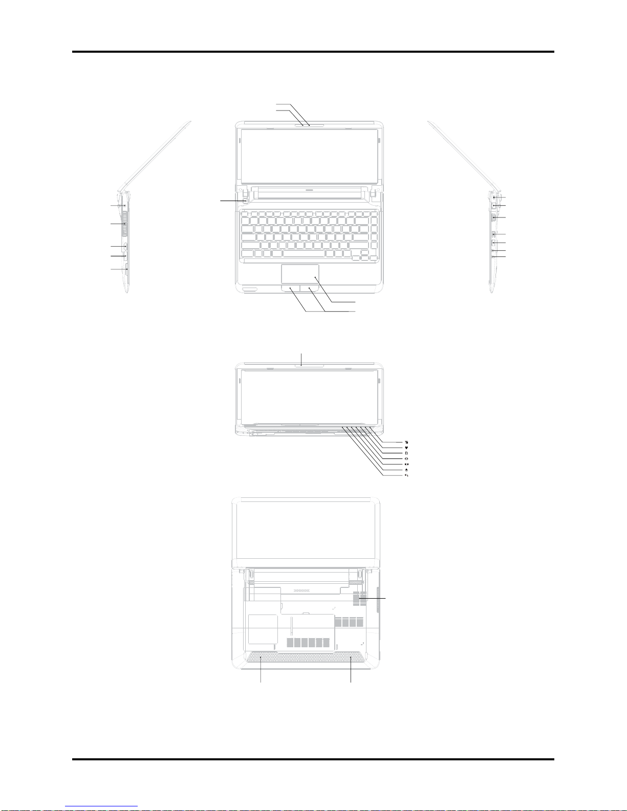
Figure 1-1A shows the computer and its system unit configuration.
Camera
Camera LED Lens Blue
:
DC-IN
Thermal Van Holes
HDMI
e-SATA
Card Reader
Power BTN
Microphone
Touch Pad
TP BTN
WiMax/3G: Blue
Wireless / RF status: Amber
Bridge Media: White
HDD/ODD/e-SATA: White
Main Battery: /Amber/Amber<Blink>White
Power: /Amber<Blink>White
DC-IN:White
Kensington Lock
RJ-45
VGA
USB
USB
Microphone (Chrome ring)
Headphone (Chrome ring)
Figure 1-1A ID Parts Description Placement Part A
Satellite/Satellite PRO T230D Maintenance Manual 1-5
Speaker
Bottom Door
Battery
Speaker
Thermal Van Holes
1 Hardware Overview
Satellite/Satellite PRO T230D Maintenance Manual 1-6

1 Hardware Overview
The system unit of the computer consists of the following components:
Processor (BTO)
The computer is equipped with one of the following AMD processors:
AMD Geneva Nile Dual-Core Processors
Memory (BTO)
The computer has two SODIMM slots which come standard with 1GB/2GB/4GB, accepting
BTO for your memory requirements. It can incorporate up to 8 GB of main memory. It
supports DDR3 at 800MHz.
BIOS ROM (EEPROM)
The system BIOS and Keyboard BIOS share one single 1024KB flash ROM. The flash
utility can be used to program both system and keyboard BIOS at the same time.
System Controllers
Advanced Power Management 1.2 support
ACPI2.0b and Windows Logo Program 3.0 compliant
Support SMBus specification V2.0
Hot keys for system control
Audio volume output control
External LED control
Battery scope report and control
Sticky key support
Power switch control
Two host interface channels support
Supports three independent devices
Internal Keyboard country selection
Computrace
Satellite/Satellite PRO T230D Maintenance Manual 1-7

1 Hardware Overview
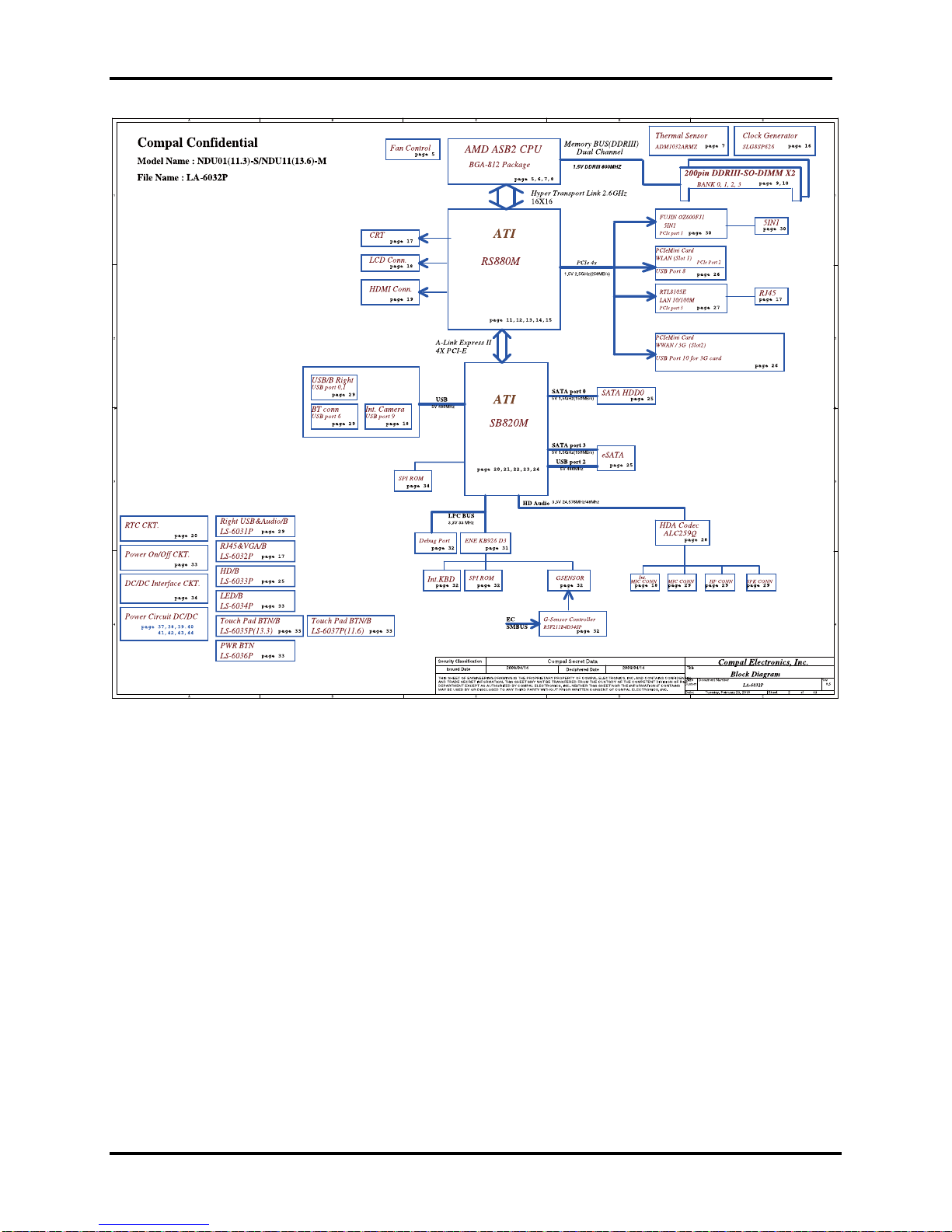
Graphics Controller
AMD RS880M Chipset for integrated graphics display
Audio Controller
Realtek Azalia ALC259-GR
One Audio-in port: Mic-in/Line-in
One Audio-out port: Headphone-out/Line-out
Internal Microphone (with Internal Camera, MIC with echo cancellation)
Volume control: Digital control
Microsoft inbox audio driver support
Hardware EQ support
Wireless LAN Controller
Realtek 802.11 b/g/n RTL8191SE (1x2)
Atheros 802.11 b/g HB95 (1x1)
Broadcom 802.11 bgn/bg BCM4313 (WLAN/BT) w/Bluetooth V3.0+HS
Satellite/Satellite PRO T230D Maintenance Manual 1-8

1 Hardware Overview
1.2 2.5-inch HDD
The computer contains an extremely low-profile and lightweight, high-performance HDD. The
HDD incorporates a 9.5 mm magnetic disk and mini-Winchester type magnetic heads. The HDD
interface conforms to Serial ATA. Storage capacities supported are 160, 250, 320, 400, 500 and
640 GB.
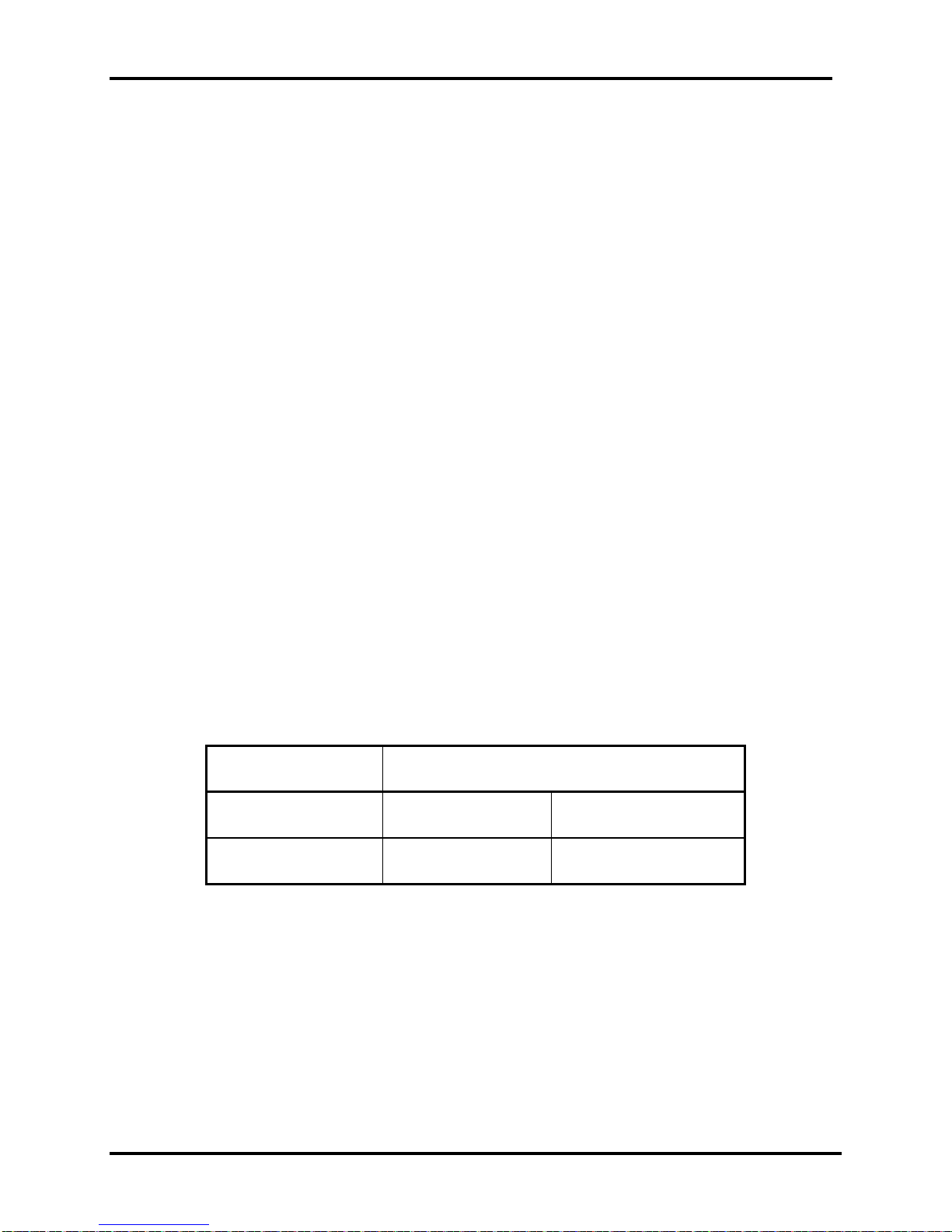
The HDD is shown in Figure 1-2 and some of its specifications are listed in Table 1-1.
Figure 1-2 SATA HDD
Table 1-1 HDD Specifications
Item
Capacity (GB)
Rotational Speed (RPM)
Height
User Data Sectors
Bytes / Sector 512 512 512
160G 250G 320 GB
5400 RPM 5400 or 7200 RPM 5400 or 7200 RPM
9.5 mm 9.5 mm 9.5 mm
312,581,808 488,397,168 625,142,448
Specifications
Item
Capacity (GB)
Rotational Speed (RPM)
Height
User Data Sectors
500G 640 GB
5400 or 7200 RPM 5400 RPM
9.5 mm 9.5 mm
976,773,168 1,250,263,728
Specifications
Bytes / Sector 512 512
Satellite/Satellite PRO T230D Maintenance Manual 1-9

1 Hardware Overview
1.3 Power Supply
The power supply unit provides constant voltage (19V) for the system board and performs the
following functions:
1. Power input monitor
y Checks whether the AC adapter (DC power supply) is connected to the computer.
y Checks whether the battery pack is connected to the computer.
y Monitors the DC power supply input voltage (AC Adapter output voltage).
2. Power supply's internal control
y Turns on and off the battery pack charging power supply.
y Issues a charging current instruction to the PWM control IC of the battery pack charging
power supply.
y Controls the supply of DC power supply input (AC Adapter output) to the power supply
unit.
y Controls the supply of power to the system block (load/logic circuit side).
y Controls forced shutdown if the power supply malfunctions.
3. Logic circuit control
y Instructs the gate array to enable/disable tuning the power on.
y Controls power-on/off operation.
4. Status display
y Turns on the Power LED (in White).
y Battery indicator (in White or Amber).
y DC-IN indicator (in White)
5. External interface
y Performs communication through the I2C bus (via the internal EC/KBC).
y Transfers the power supply operation mode.
Satellite/Satellite PRO T230D Maintenance Manual 1-10

1 Hardware Overview
6. Output monitor
y Monitors the voltage output to the system block (load/logic circuit side).
y Monitors the voltage, over-voltage, input/output current of the battery pack.
y Monitors the internal temperature of the battery pack.
y Monitors the supply voltage from the AC adapter.
Satellite/Satellite PRO T230D Maintenance Manual 1-11
1 Hardware Overview
1.4 Batteries
The computer has the following two types of batteries:
Main Battery Pack
Real Time Clock (RTC) Battery
1.4.1 Main Battery
The main battery pack serves as the computer's main power source when the AC adapter is not
attached. The main battery maintains the state of the computer when the AC adapter is detached.
1.4.2 Battery Charging Control
Battery charging is controlled by EC KB926. When the AC adapter and battery pack are attached
to the computer, the EC KB926 controls the charge on/off state and detects a full charge.
Battery Charge
When the AC adapter is attached, the battery is charged by off-state charge when the system
is powered off or by on-state charge when it is powered on.
Table 1-2 Quick/Normal Charging Time
State Charge Time
Off-State Charge 6 Cell About 4 hours max
On-State Charge 6 Cell About 12 hours max
Satellite/Satellite PRO T230D Maintenance Manual 1-12

1 Hardware Overview
NOTE: The time required for normal charge depends on the power consumption by the
system. Using a fluorescent lamp and frequently accessing the disk consumes more power and
lengthens the charge time.
Any of the following can stops battery charge:
1. The battery becomes fully charged.
2. The AC adapter or battery pack is removed.
3. The battery or AC adapter voltage is abnormal.
Detection of full charge
A full charge is detected only when the battery is being charged by quick or normal charge.
A full charge is detected when either of the following conditions is met:
1. The current in the battery charging circuit drops below the predetermined value.
2. The charging time exceeds the fixed limit.
1.4.3 RTC Battery
The RTC battery provides power to keep the current date, time and other system information in
memory while the computer is turned off.
Satellite/Satellite PRO T230D Maintenance Manual 1-13

Chapter 2
Troubleshooting Procedures
 Loading...