


User's Manual
Satellite Pro S850
Series

Table of Contents
Preface
General Precautions
Chapter 1
Getting Started
Equipment checklist ............................................................................. 1-1
Getting Started ....................................................................................... 1-2
Chapter 2
The Grand Tour
Front with the display closed ............................................................... 2-1
Internal Hardware Components ......................................................... 2-11
Chapter 3
Operating Basics
Using the Touch Pad ............................................................................. 3-1
The Keyboard ......................................................................................... 3-1
Using the Fingerprint Sensor ............................................................... 3-8
Optical disc drives .............................................................................. 3-14
TOSHIBA Disc Creator ........................................................................ 3-20
TOSHIBA VIDEO PLAYER ................................................................... 3-22
Modem .................................................................................................. 3-24
Wireless communications .................................................................. 3-27
LAN ....................................................................................................... 3-31
Optional devices .................................................................................. 3-32
ExpressCard ........................................................................................ 3-32
PC Card ................................................................................................ 3-33
Memory media ..................................................................................... 3-35
Additional memory module ................................................................ 3-39
External monitor .................................................................................. 3-43
Mini DisplayPort .................................................................................. 3-44
eSATA (External Serial ATA) device .................................................. 3-45
Serial port ............................................................................................. 3-46
Security lock ........................................................................................ 3-46
Optional TOSHIBA Accessories ........................................................ 3-47
Sound System ...................................................................................... 3-47
Video mode .......................................................................................... 3-49
Computer Handling ............................................................................. 3-49
Heat dispersal ...................................................................................... 3-50
Chapter 4
Utilities & Advanced Usage
User's Manual ii

Utilities and Applications ...................................................................... 4-1
Special features ..................................................................................... 4-7
Using the TOSHIBA Sleep Utility ......................................................... 4-9
Using the TOSHIBA Face Recognition .............................................. 4-12
TOSHIBA Password Utility ................................................................. 4-15
HW Setup .............................................................................................. 4-18
TOSHIBA PC Health Monitor .............................................................. 4-23
Using the Hard Disk Drive (HDD) Protection .................................... 4-26
TOSHIBA HDD Protection Properties ................................................ 4-26
System Recovery ................................................................................ 4-28
Chapter 5
Power and Power-Up Modes
Power conditions ................................................................................... 5-1
Monitoring of power condition ............................................................. 5-2
Battery .................................................................................................... 5-3
Power-up modes .................................................................................... 5-9
Panel power on/off .............................................................................. 5-10
System automatic Sleep/Hibernation ................................................ 5-10
Chapter 6
Troubleshooting
Problem solving process ...................................................................... 6-1
Hardware and system checklist ........................................................... 6-4
TOSHIBA support ................................................................................ 6-20
Appendix A
Specifications
Appendix B
AC Power Cord and Connectors
Appendix C
Legal Footnotes
Appendix D
Information for Wireless Devices
Index
Glossary
User's Manual
iii

Copyright
© 2012 by TOSHIBA Corporation. All rights reserved. Under the copyright
laws, this manual cannot be reproduced in any form without the prior
written permission of TOSHIBA. No patent liability is assumed, with respect
to the use of the information contained herein.
First edition April 2012
Copyright authority for music, movies, computer programs, databases and
other intellectual property covered by copyright laws belongs to the author
or to the copyright owner. Copyrighted material can be reproduced only for
personal use or use within the home. Any other use beyond that stipulated
above (including conversion to digital format, alteration, transfer of copied
material and distribution on a network) without the permission of the
copyright owner is a violation of copyright or author's rights and is subject
to civil damages or criminal action. Please comply with copyright laws in
making any reproduction from this manual.
Disclaimer
This manual has been validated and reviewed for accuracy. The
instructions and descriptions it contains are accurate for your computer at
the time of this manual’s production. However, succeeding computers and
manuals are subject to change without notice. TOSHIBA assumes no
liability for damages incurred directly or indirectly from errors, omissions or
discrepancies between the computer and the manual.
Trademarks
Intel, Intel SpeedStep, Intel Core and Centrino are trademarks or registered
trademarks of Intel Corporation.
Windows, Microsoft and Windows logo are registered trademarks of
Microsoft Corporation.
Bluetooth is a trademark owned by its proprietor and used by TOSHIBA
under license.
Photo CD is a trademark of Eastman Kodak Company.
ConfigFree is a trademark of TOSHIBA Corporation.
TouchPad is a trademark of Synaptics, Inc
Wi-Fi is a registered trademark of the Wi-Fi Alliance.
Secure Digital and SD are trademarks of SD Card Association.
Memory Stick, Memory Stick Duo, Memory Stick PRO, Memory Stick PRO
Duo and Memory Stick Micro are trademarks or registered trademarks of
Sony Corporation.
xD-Picture Card is a trademark of FUJIFILM Corporation.
ExpressCard is a trademark of PCMCIA.
MultiMediaCard and MMC are trademarks of MultiMediaCard Association.
User's Manual
iv

QUALCOMM is a trademark of Qualcomm Incorporated, registered in the
United States and other countries. ATHEROS is a trademark of Qualcomm
Atheros, Inc., registered in the United States and other countries.
Realtek is a registered trademark of Realtek Semiconductor Corporation.
Other trademarks and registered trademarks not listed above may be used
in this manual.
FCC information
FCC notice "Declaration of Conformity Information"
This equipment has been tested and found to comply with the limits for a
Class B digital device, pursuant to part 15 of the FCC rules. These limits
are designed to provide reasonable protection against harmful interference
in a residential installation. This equipment generates, uses and can
radiate radio frequency energy and, if not installed and used in accordance
with the instructions, may cause harmful interference to radio
communications. However, there is no guarantee that interference will not
occur in a particular installation. If this equipment does cause harmful
interference to radio or television reception, which can be determined by
turning the equipment off and on, the user is encouraged to try to correct
the interference by one or more of the following measures:
Reorient or relocate the receiving antenna.
Increase the separation between the equipment and receiver.
Connect the equipment into an outlet on a circuit different from that to
which the receiver is connected.
Consult the dealer or an experienced radio/TV technician for help.
Only peripherals complying with the FCC class B limits may be attached to
this equipment. Operation with non-compliant peripherals or peripherals not
recommended by TOSHIBA is likely to result in interference to radio and
TV reception. Shielded cables must be used between the external devices
and the computer’s External RGB monitor port, Universal Serial Bus (USB
2.0 and 3.0) ports, eSATA/USB combo port, Mini DisplayPort, serial port
and microphone jack. Changes or modifications made to this equipment,
not expressly approved by TOSHIBA or parties authorized by TOSHIBA
could void the user’s authority to operate the equipment.
FCC conditions
This device complies with part 15 of the FCC Rules. Operation is subject to
the following two conditions:
1. This device may not cause harmful interference.
2. This device must accept any interference received, including
interference that may cause undesired operation.
User's Manual
v

Contact
Address: TOSHIBA America Information Systems, Inc.
9740 Irvine Boulevard
Irvine, California 92618-1697
Telephone: (949) 583-3000
EU Declaration of Conformity
This product is carrying the CE-Mark in accordance with
the related European Directives. Responsible for CEMarking is TOSHIBA Europe GmbH, Hammfelddamm 8,
41460 Neuss, Germany. The complete and official EU
Declaration of Conformity can be found on TOSHIBA’s
web site http://epps.toshiba-teg.com on the Internet.
CE compliance
This product is labelled with the CE Mark in accordance with the related
European Directives, notably Electromagnetic Compatibility Directive
2004/108/EC for the notebook and the electronic accessories including the
supplied power adapter, the Radio Equipment and Telecommunications
Terminal Equipment Directive 1999/5/EC in case of implemented
telecommunication accessories and the Low Voltage Directive 2006/95/EC
for the supplied power adapter. Furthermore the product complies with the
Ecodesign Directive 2009/125/EC (ErP) and its related implementing
measures.
This product and the original options are designed to observe the related
EMC (Electromagnetic Compatibility) and safety standards. However,
TOSHIBA cannot guarantee that this product still observes these EMC
standards if options or cables not produced by TOSHIBA are connected or
implemented. In this case the persons who have connected/implemented
those options/cables have to provide assurance that the system (PC plus
options/cables) still fulfils the required standards. To avoid general EMC
problems, the following guidance should be noted:
Only CE marked options should be connected/implemented
Only best shielded cables should be connected
Working environment
This product was designed to fulfil the EMC (Electromagnetic Compatibility)
requirements to be observed for so-called “Residential, commercial and
light industry environments”. TOSHIBA do not approve the use of this
product in working environments other than the above mentioned
“Residential, commercial and light industry environments”.
For example, the following environments are not approved:
User's Manual
vi

Industrial Environments (e.g. environments where a mains voltage of
380 V three-phase is used)
Medical Environments
Automotive Environments
Aircraft Environments
Any consequences resulting from the use of this product in working
environments that are not approved are not the responsibility of TOSHIBA.
The consequences of the use of this product in non-approved working
environments may be:
Interference with other devices or machines in the near surrounding
area.
Malfunction of, or data loss from, this product caused by disturbances
generated by other devices or machines in the near surrounding area.
Therefore TOSHIBA strongly recommend that the electromagnetic
compatibility of this product should be suitably tested in all non-approved
working environments before use. In the case of automobiles or aircraft,
the manufacturer or airline respectively should be asked for permission
before use of this product.
Furthermore, for general safety reasons, the use of this product in
environments with explosive atmospheres is not permitted.
VCCI Class B Information
この装置は、クラスB情報技術装置です。この装置は、家庭環境で使
用することを目的としていますが、この装置がラジオやテレビジョン
受信機に近接して使用されると、受信障害を引き起こすことがあります。
取扱説明書に従って正しい取り扱いをしてください。
VCCI-B
Video Standard Notice
THIS PRODUCT IS LICENSED UNDER THE AVC, THE VC-1 AND
MPEG-4 VISUAL PATENT PORTFOLIO LICENSE FOR THE PERSONAL
AND NON-COMMERCIAL USE OF A CONSUMER FOR (I) ENCODING
VIDEO IN COMPLIANCE WITH THE ABOVE STANDARDS ("VIDEO")
AND/OR (II) DECODING AVC, VC-1 AND MPEG-4 VIDEO THAT WAS
ENCODED BY A CONSUMER ENGAGED IN A PERSONAL AND NONCOMMERCIAL ACTIVITY AND/OR WAS OBTAINED FROM A VIDEO
PROVIDER LICENSED BY MPEG LA TO PROVIDE SUCH VIDEO. NO
LICENSE IS GRANTED OR SHALL BE IMPLIED FOR ANY OTHER USE.
ADDITIONAL INFORMATION INCLUDING THAT RELATING TO
PROMOTIONAL, INTERNAL AND COMMERCIAL USES AND
LICENSING MAY BE OBTAINED FROM MPEG LA, L.L.C. SEE HTTP://
WWW.MPEGLA.COM.
User's Manual
vii

Canadian regulatory information (Canada only)
This digital apparatus does not exceed the Class B limits for radio noise
emissions from digital apparatus as set out in the Radio Interference
Regulation of the Canadian Department of Communications.
Note that Canadian Department of Communications (DOC) regulations
provide, that changes or modifications not expressly approved by
TOSHIBA Corporation could void your authority to operate this equipment.
This Class B digital apparatus meets all requirements of the Canadian
Interference-Causng Equipment Regulations.
Cet appareil numérique de la class B respecte toutes les exgences du
Règlement sur le matériel brouileur du Canada.
Modem warning notice
This information is applicable to the models equipped with a built-in
modem.
Conformity Statement
The equipment has been approved to [Commission Decision "CTR21"] for
pan-European single terminal connection to the Public Switched Telephone
Network (PSTN).
However, due to differences between the individual PSTNs provided in
different countries/regions the approval does not, of itself, give an
unconditional assurance of successful operation on every PSTN network
termination point.
In the event of problems, you should contact your equipment supplier in the
first instance.
Network Compatibility Statement
This product is designed to work with, and is compatible with the following
networks. It has been tested to and found to conform with the additional
requirements conditional in EG 201 121.
Germany ATAAB AN005,AN006,AN007,AN009,AN010
and DE03,04,05,08,09,12,14,17
Greece ATAAB AN005,AN006 and GR01,02,03,04
Portugal ATAAB AN001,005,006,007,011 and
P03,04,08,10
Spain ATAAB AN005,007,012, and ES01
Switzerland ATAAB AN002
All other countries/regions ATAAB AN003,004
User's Manual viii
Specific switch settings or software setup are required for each network,
please refer to the relevant sections of the user guide for more details.
The hookflash (timed break register recall) function is subject to separate
national type approvals. It has not been tested for conformity to national
type regulations, and no guarantee of successful operation of that specific
function on specific national networks can be given.
Japan regulations
Region selection
If you are using the computer in Japan, technical regulations described in
the Telecommunications Business Law require that you select the Japan
region mode. It is illegal to use the modem in Japan with any other
selection.
Redial
Up to two redial attempts can be made. If more than two redial attempts
are made, the modem will return Black Listed. If you are experiencing
problems with the Black Listed code, set the interval between redials at one
minute or longer.
Japan’s Telecommunications Business Law permits up to two redials on
analogue telephones, but the redials must be made within a total of three
minutes.
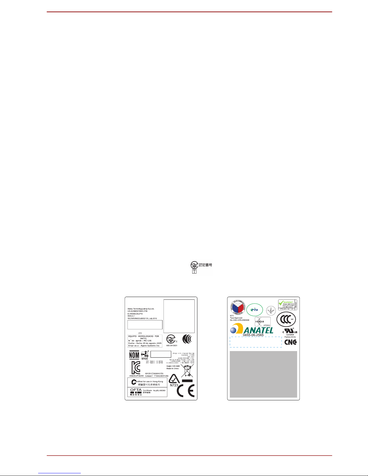
The internal modem is approved by Japan Approvals Institute for
Telecommunications Equipment.
A05-0413001
This label is located on the module.
中国制造
TRA
REGISTERED No:
ER0045497/10
DEALER No:
DA0045491/10
CCAG10M10010T2
04604/I/R/POSTEL/2010
2457
Agere Systems
Delphi Modem D40
Revision AM5
Approval No. 3785
Agere Delphi Modem D40 (AM5)
54-5681
Agere Systems Inc.
AGREE PAR L’ARNT MARCO
Numéro d’agrément: MF 2514 ANRT 2005
Date d’agrément: 31 AOUT2005
Pakistan Telecom Authority
Approved by PTA (2007)
内置调制解调器
D40 AM5
TE-2009/176
MDC Modem Module
Rating:3.3V
Pursuant to FCC CFR 47, Part 68:
When you are ready to install or use the modem, call your local telephone
company and give them the following information:
User's Manual
ix

The telephone number of the line to which you will connect the modem
The registration number that is located on the device
The FCC registration number of the modem will be found on either the
device which is to be installed, or, if already installed, on the bottom of
the computer outside of the main system label.
The Ringer Equivalence Number (REN) of the modem, which can
vary. For the REN of your modem, refer to your modem’s label.
The modem connects to the telephone line by means of a standard jack
called the USOC RJ11C.
Type of service
Your modem is designed to be used on standard-device telephone lines.
Connection to telephone company-provided coin service (central office
implemented systems) is prohibited. Connection to party lines service is
subject to state tariffs. If you have any questions about your telephone line,
such as how many pieces of equipment you can connect to it, the
telephone company will provide this information upon request.
Telephone company procedures
The goal of the telephone company is to provide you with the best service it
can. In order to do this, it may occasionally be necessary for them to make
changes in their equipment, operations, or procedures. If these changes
might affect your service or the operation of your equipment, the telephone
company will give you notice in writing to allow you to make any changes
necessary to maintain uninterrupted service.
If problems arise
If any of your telephone equipment is not operating properly, you should
immediately remove it from your telephone line, as it may cause harm to
the telephone network. If the telephone company notes a problem, they
may temporarily discontinue service. When practical, they will notify you in
advance of this disconnection. If advance notice is not feasible, you will be
notified as soon as possible. When you are notified, you will be given the
opportunity to correct the problem and informed of your right to file a
complaint with the FCC. In the event repairs are ever needed on your
modem, they should be performed by TOSHIBA Corporation or an
authorized representative of TOSHIBA Corporation.
Disconnection
If you should ever decide to permanently disconnect your modem from its
present line, please call the telephone company and let them know of this
change.
User's Manual
x

Fax branding
The Telephone Consumer Protection Act of 1991 makes it unlawful for any
person to use a computer or other electronic device to send any message
via a telephone fax machine unless such message clearly contains in a
margin at the top or bottom of each transmitted page or on the first page of
the transmission, the date and time it is sent and an identification of the
business, other entity or individual sending the message and the telephone
number of the sending machine or such business, other entity or individual.
In order to program this information into your fax modem, you should
complete the setup of your fax software before sending messages.
Use only No. 26AWG or larger modular cable.
Instructions for IC CS-03 certified equipment
1. The Industry Canada label identifies certified equipment. This
certification means that the equipment meets certain
telecommunications network protective, operational and safety
requirements as prescribed in the appropriate Terminal Equipment
Technical Requirements document(s). The Department does not
guarantee the equipment will operate to the user’s satisfaction.
Before installing this equipment, users should ensure that it is
permissible to be connected to the facilities of the local
telecommunications company. The equipment must also be installed
using an acceptable method of connection.
The customer should be aware that compliance with the above
conditions may not prevent degradation of service in some situations.
Repairs to certified equipment should be coordinated by a
representative designated by the supplier. Any repairs or alterations
made by the user to this equipment, or equipment malfunctions, may
give the telecommunications company cause to request the user to
disconnect the equipment.
Users should ensure for their own protection that the electrical ground
connections of the power utility, telephone lines and internal metallic
water pipe systems, if present, are connected together. This
precaution may be particularly important in rural areas.
Users should not attempt to make such connections themselves, but
should contact the appropriate electric inspection authority, or electrician,
as appropriate.
User's Manual xi

2. The user manual of analog equipment must contain the equipment’s
Ringer Equivalence Number (REN) and an explanation notice similar
to the following:
The Ringer Equivalence Number (REN) of the modem, which can
vary. For the REN of your modem, refer to your modem’s label.
The Ringer Equivalence Number (REN) assigned to each terminal device
provides an indication of the maximum number of terminals allowed to be
connected to a telephone interface. The termination on an interface may
consist of any combination of devices subject only to the requirement that
the sum of the Ringer Equivalence Numbers of all the devices does not
exceed 5.
3. The standard connecting arrangement (telephone jack type) for this
equipment is jack type(s): USOC RJ11C. The IC registration number
of the modem is shown below.
Canada: 4005B-DELPHI
Notes for Users in Australia and New Zealand
Modem warning notice for Australia
Modems connected to the Australian telecoms network must have a valid
Austel permit. This modem has been designed to specifically configure to
ensure compliance with Austel standards when the country/region selection
is set to Australia. The use of other country/region setting while the modem
is attached to the Australian PSTN would result in you modem being
operated in a non-compliant manner. To verify that the country/region is
correctly set, enter the command ATI which displays the currently active
setting.
To set the country/region permanently to Australia, enter the following
command sequence:
AT%TE=1
ATS133=1
AT&F
AT&W
AT%TE=0
ATZ
Failure to set the modem to the Australia country/region setting as shown
above will result in the modem being operated in a non-compliant manner.
Consequently, there would be no permit in force for this equipment and the
Telecoms Act 1991 prescribes a penalty of $12,000 for the connection of
non-permitted equipment.
User's Manual
xii

Notes for use of this device in New Zealand
The grant of a Telepermit for a device in no way indicates Telecom
acceptance of responsibility for the correct operation of that device
under all operating conditions. In particular the higher speeds at which
this modem is capable of operating depend on a specific network
implementation which is only one of many ways of delivering high
quality voice telephony to customers. Failure to operate should not be
reported as a fault to Telecom.
In addition to satisfactory line conditions a modem can only work
properly if:
1. it is compatible with the modem at the other end of the call and.
2. the application using the modem is compatible with the
application at the other end of the call - e.g., accessing the
Internet requires suitable software in addition to a modem.
This equipment shall not be used in any manner which could
constitute a nuisance to other Telecom customers.
Some parameters required for compliance with Telecom’s PTC
Specifications are dependent on the equipment (PC) associated with
this modem. The associated equipment shall be set to operate within
the following limits for compliance with Telecom Specifications:
1. There shall be no more than 10 call attempts to the same number
within any 30 minute period for any single manual call initiation,
and
2. The equipment shall go on-hook for a period of not less than 30
seconds between the end of one attempt and the beginning of the
next.
3. Automatic calls to different numbers shall be not less than 5
seconds apart.
Immediately disconnect this equipment should it become physically
damaged, and arrange for its disposal or repair.
The correct settings for use with this modem in New Zealand are as
follows:
ATB0 (CCITT operation)
AT&G2 (1800 Hz guard tone)
AT&P1 (Decadic dialing make-break ratio =33%/67%)
ATS0=0 (not auto answer) ATS6=4 (Blind dial delay)
ATS7=less than 90 (Time to wait to carrier after dialing)
ATS10=less than 150 (loss of carrier to hangup delay, factory default
of 15 recommended)
ATS11=90 (DTMF dialing on/off duration=90 ms)
ATX2 (Dial tone detect, but not (U.S.A.) call progress detect)
When used in the Auto Answer mode, the S0 register must be set with
a value of 3 or 4. This ensures:
User's Manual
xiii

A person calling your modem will hear a short burst of ringing before
the modem answers. This confirms that the call has been successfully
switched through the network.
Caller identification information (which occurs between the first and
second ring cadences) is not destroyed.
The preferred method of dialing is to use DTMF tones (ATDT...) as
this is faster and more reliable than pulse (decadic) dialing. If for some
reason you must use decadic dialing, your communications program
must be set up to record numbers using the following translation table
as this modem does not implement the New Zealand “Reverse
Dialing” standard.
Number to be dialed: 0 1 2 3 4 5 6 7 8 9
Number to program into computer: 0 9 8 7 6 5 4 3 2 1
Note that where DTMF dialing is used, the numbers should be
entered normally.
The transmit level from this device is set at a fixed level and because
of this there may be circumstances where the performance is less
than optimal. Before reporting such occurrences as faults, please
check the line with a standard Telepermitted telephone, and only
report a fault if the phone performance is impaired.
It is recommended that this equipment be disconnected from the
Telecom line during electrical storms.
When relocating the equipment, always disconnect the Telecom line
connection before the power connection, and reconnect the power
first.
This equipment may not be compatible with Telecom Distinctive Alert
cadences and services such as FaxAbility.
NOTE THAT FAULT CALLOUTS CAUSED BY ANY OF THE
ABOVE CAUSES MAY INCUR A CHARGE FROM TELECOM
User's Manual
xiv
Following information is only valid for EU-member
States:
Disposal of products
The crossed out wheeled dust bin symbol indicates that
products must be collected and disposed of separately
from household waste. Integrated batteries and
accumulators can be disposed of with the product. They
will be separated at the recycling centres.
The black bar indicates that the product was placed on the
market after August 13, 2005.
By participating in separate collection of products and
batteries, you will help to assure the proper disposal of
products and batteries and thus help to prevent potential
negative consequences for the environment and human
health.
For more detailed information about the collection and
recycling programmes available in your country, please
visit our website (http://eu.computers.toshiba-europe.com)
or contact your local city office or the shop where you
purchased the product.
Disposal of batteries and/or accumulators
The crossed out wheeled dust bin symbol indicates that
batteries and/or accumulators must be collected and
disposed of separately from household waste.
If the battery or accumulator contains more than the
specified values of lead (Pb), mercury (Hg), and/or
cadmium (Cd) defined in the Battery Directive (2006/66/
EC), then the chemical symbols for lead (Pb), mercury
(Hg) and/or cadmium (Cd) will appear below the crossed
out wheeled dust bin symbol.
By participating in separate collection of batteries, you will
help to assure the proper disposal of products and
batteries and thus help to prevent potential negative
consequences for the environment and human health.
For more detailed information about the collection and
recycling programmes available in your country, please
visit our website (http://eu.computers.toshiba-europe.com)
or contact your local city office or the shop where you
purchased the product.
User's Manual xv
These symbols may not stick depending on the country and region where
you purchased.
Following information is only for India:
The use of this symbol indicates that this product may not
be treated as household waste.
By ensuring this product is disposed of correctly, you will
help prevent potential negative consequences for the
environment and human health, which could otherwise be
caused by inappropriate waste handling of this product.
For more detailed information about recycling of this
product, please visit our website (http://www.toshibaindia.com) or contact call center (1800-200-8674).
These symbols may not stick depending on the country and region where
you purchased.
Disposing of the computer and the computer's
batteries
Discard this computer in accordance with applicable laws and
regulations. For further information, contact your local government.
This computer contains rechargeable batteries. After repeated use,
the batteries will finally lose their ability to hold a charge and you will
need to replace them. Under certain applicable laws and regulation, it
may be illegal to dispose of old batteries by placing them in the trash.
Please be kind to our shared environment. Check with your local
government authority for details regarding where to recycle old
batteries or how to dispose of them properly.
REACH - Compliance Statement
The new European Union (EU) chemical regulation, REACH (Registration,
Evaluation, Authorization and Restriction of Chemicals), entered into force
on 1 June 2007. TOSHIBA will meet all REACH requirements and is
committed to provide our customers with information about the chemical
substances in our products according to REACH regulation.
Please consult the following website
www.toshiba-europe.com/computers/
info/reach for information about the presence in our articles of substances
included on the candidate list according to article 59(1) of Regulation (EC)
No 1907/2006 („REACH“) in a concentration above 0.1 % weight by weight.
User's Manual
xvi

Following information is only for Turkey:
Compliant with EEE Regulations: TOSHIBA meets all requirements of
Turkish regulation 26891 “Restriction of the use of certain hazardous
substances in electrical and electronic equipment”.
The number of possible pixel failures of your display is defined
according to ISO 9241-307 standards. If the number of pixel failures is
less than this standard, they will not be counted as defect or failure.
Battery is a consumption product, since the battery time depends on
the usage of your computer. If the battery can not be charged at all,
then it is a defect or failure. The changes in battery time is not a defect
or failure.
ENERGY STAR® Program
Your Computer model may be ENERGY STAR
®
compliant. If the model you purchased is compliant, it is
labeled with the ENERGY STAR logo on the computer and
the following information applies.
TOSHIBA is a partner in the ENERGY STAR Program and
has designed this computer to meet the latest ENERGY
STAR guidelines for energy efficiency. Your computer
ships with the power management options preset to a
configuration that will provide the most stable operating
environment and optimum system performance for both
AC power and battery modes.
To conserve energy, your computer is set to enter the lowpower Sleep Mode which shuts down the system and
display within 15 minutes of inactivity in AC power mode.
TOSHIBA recommends that you leave this and other
energy saving features active, so that your computer will
operate at its maximum energy efficiency. You can wake
the computer from Sleep Mode by pressing the power
button.
Products that earn the ENERGY STAR prevent
greenhouse gas emissions by meeting strict energy
efficiency guidelines set by the US EPA and the EU
Commission. According to the EPA, a computer meeting
the new ENERGY STAR specifications will use between
20% and 50% less energy depending on how it is used.
Visit http://www.eu-energystar.org or http://
www.energystar.gov for more information regarding the
ENERGY STAR Program.
User's Manual
xvii
Optical disc drive safety instructions
Be sure to check the precautions at the end of this section.
The drive model employs a laser system. To ensure proper use of this
product, please read this instruction manual carefully and retain for
future reference. Should the unit ever require maintenance, contact an
authorized service location.
Use of controls, adjustments or the performance of procedures other
than those specified may result in hazardous radiation exposure.
To prevent direct exposure to the laser beam, do not try to open the
enclosure.
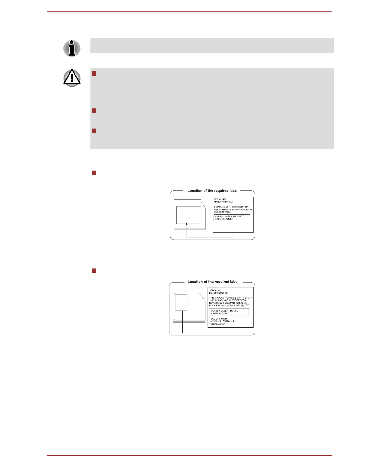
1. Panasonic Precision Devices Co., Ltd.
DVD SuperMulti with Double Layer
Panasonic Precision Devices Co., Ltd.
1080 Takano Nagomi-machi Tamana-Gun
Kumamoto, Japan
2. TEAC
DVD SuperMulti with Double Layer
User's Manual
xviii

Precautions
CAUTION: This appliance contains
a laser system and is classified as a
“CLASS 1 LASER PRODUCT.” To
use this model properly, read the
instruction manual carefully and
keep this manual for your future
reference. In case of any trouble
with this model, please contact your
nearest “AUTHORIZED service
station.” To prevent direct exposure
to the laser beam, do not try to open
the enclosure.
User's Manual xix

Preface
Congratulations on your purchase of this computer. This powerful notebook
computer provides excellent expansion capability, includes multimedia
functionality, and is designed to provide years of reliable, high-performance
computing.
This manual tells how to set up and begin using your computer. It also
provides detailed information on configuring your computer, basic
operations and care, using optional devices and troubleshooting.
Conventions
This manual uses the following formats to describe, identify, and highlight
terms and operating procedures.
Abbreviations
On first appearance, and whenever necessary for clarity, abbreviations are
enclosed in parentheses following their definition. For example: Read Only
Memory (ROM). Acronyms are also defined in the Glossary.
Icons
Icons identify ports, dials, and other parts of your computer. The indicator
panel also uses icons to identify the components it is providing information
on.
Keys
The keyboard keys are used in the text to describe many computer
operations. A distinctive typeface identifies the key top symbols as they
appear on the keyboard. For example, ENTER identifies the ENTER key.
Key operation
Some operations require you to simultaneously use two or more keys. We
identify such operations by the key top symbols separated by a plus sign
(+). For example, CTRL + C means you must hold down CTRL and at the
same time press C. If three keys are used, hold down the first two and at
the same time press the third.
ABC When procedures require an action such as
clicking an icon or entering text, the icon's name or
the text you are to type in is represented in the
typeface you see to the left.
User's Manual xx

Messages
Messages are used in this manual to bring important information to your
attention. Each type of message is identified as shown below.
Indicates a potentially hazardous situation, which could result in death or
serious injury, if you do not follow instructions.
Pay attention! A caution informs you that improper use of equipment or
failure to follow instructions may cause data loss or damage your
equipment.
Please read. A note is a hint or advice that helps you make best use of
your equipment.
Terminology
This term is defined in this document as follows:
Start
The word "Start" refers to the " " button in
Windows 7.
HDD or Hard disk
drive
Some models are equipped with a "Solid State
Drive (SSD)" instead of a hard disk drive.In this
manual, the word "HDD" or "Hard disk drive"
also refers to the SSD unless otherwise stated.
User's Manual xxi

General Precautions
TOSHIBA computers are designed to optimize safety, minimize strain and
withstand the rigors of portability. However, certain precautions should be
observed to further reduce the risk of personal injury or damage to the
computer.
Be certain to read the general precautions below and to note the cautions
included in the text of the manual.
Provide adequate ventilation
Always make sure your computer and AC adaptor have adequate
ventilation and are protected from overheating when the power is turned on
or when an AC adaptor is connected to a power outlet (even if your
computer is in Sleep Mode). In this condition, observe the following:
Never cover your computer or AC adaptor with any object.
Never place your computer or AC adaptor near a heat source, such as
an electric blanket or heater.
Never cover or block the air vents including those located at the base
of the computer.
Always operate your computer on a hard flat surface. Using your
computer on a carpet or other soft material can block the vents.
Always provide sufficient space around the computer.
Overheating your computer or AC adaptor could cause system failure,
computer or AC adaptor damage or a fire, possibly resulting in serious
injury.
Creating a computer-friendly environment
Place the computer on a flat surface that is large enough for the computer
and any other items you are using, such as a printer.
Leave enough space around the computer and other equipment to provide
adequate ventilation. Otherwise, they may overheat.
To keep your computer in prime operating condition, protect your work area
from:
Dust, moisture, and direct sunlight.
Equipment that generates a strong electromagnetic field, such as
stereo speakers (other than speakers that are connected to the
computer) or speakerphones.
Rapid changes in temperature or humidity and sources of temperature
change such as air conditioner vents or heaters.
Extreme heat, cold, or humidity.
Liquids and corrosive chemicals.
User's Manual
xxii

Stress injury
Carefully read the Instruction Manual for Safety and Comfort. It contains
information on the prevention of stress injuries to your hands and wrists
that can be caused by extensive keyboard use. It also includes information
on work space design, posture and lighting that can help reduce physical
stress.
Heat injury
Avoid prolonged physical contact with the computer. If the computer is
used for long periods, its surface can become very warm. While the
temperature will not feel hot to the touch, if you maintain physical
contact with the computer for a long time, for example if you rest the
computer on your lap or if you keep your hands on the palm rest, your
skin might suffer a low-heat injury.
If the computer has been used for a long time, avoid direct contact
with the metal plate supporting the various interface ports as this can
become hot.
The surface of the AC adaptor can become hot when in use but this
condition does not indicate a malfunction. If you need to transport the
AC adaptor, you should disconnect it and let it cool before moving it.
Do not lay the AC adaptor on a material that is sensitive to heat as the
material could become damaged.
Pressure or impact damage
Do not apply heavy pressure to the computer or subject it to any form of
strong impact as this can damage the computer's components or otherwise
cause it to malfunction.
PC Card/ExpressCard overheating
Some PC Cards/ExpressCards can become hot during prolonged use
which may result in errors or instability in the operation of the device in
question. In addition, you should also be careful when you remove a PC
Card/ExpressCard that has been used for a long time.
Mobile phones
Please be aware that the use of mobile phones can interfere with the audio
system. The operation of the computer will not be impaired in any way, but
it is recommended that a minimum distance of 30cm is maintained between
the computer and a mobile phone that is in use.
Instruction Manual for Safety and Comfort
All important information on the safe and proper use of this computer is
described in the enclosed Instruction Manual for Safety and Comfort. Be
sure to read it before using the computer.
User's Manual
xxiii

Chapter 1
Getting Started
This chapter provides an equipment checklist, and basic information to
start using your computer.
Some of the features described in this manual may not function properly if
you use an operating system that was not pre-installed by TOSHIBA.
Equipment checklist
Carefully unpack your computer, taking care to save the box and
packaging materials for future use.
Hardware
Check to make sure you have all the following items:
TOSHIBA Portable Personal Computer
AC adaptor and power cord (2-pin plug or 3-pin plug)
Battery pack (Is preinstalled in some computers)
Documentation
User Information Guide
Instruction Manual for Safety and Comfort
If any of the items are missing or damaged, contact your dealer
immediately.
Software
The following Windows® operating system and utility software are preinstalled.
Windows 7
TOSHIBA Recovery Media Creator
TOSHIBA Assist
TOSHIBA ConfigFree™
TOSHIBA Flash Cards
TOSHIBA Disc Creator
TOSHIBA Resolution+ Plug-in For Windows Media Player
TOSHIBA eco Utility
TOSHIBA Bulletin Board
User's Manual
1-1

TOSHIBA ReelTime
TOSHIBA HWSetup Utility
TOSHIBA Web Camera Application
TOSHIBA Face Recognition
TOSHIBA HDD Protection
TOSHIBA Service Station
TOSHIBA PC Health Monitor
TOSHIBA Sleep Utility
TOSHIBA Fingerprint Utility
User's Manual (this manual)
You may not have all the softwares listed above depending on the model
you purchased.
Getting Started
All users should be sure to read the section Starting up for the first
time.
Be sure to read the enclosed Instruction Manual for Safety and
Comfort for information on the safe and proper use of this computer. It
is intended to help you be more comfortable and productive while
using a notebook computer. By following the recommendations in it
you may reduce your chance of developing a painful or disabling injury
to your hand, arms, shoulders or neck.
This section provides basic information to start using your computer. It
covers the following topics:
Connecting the AC adaptor
Opening the display
Turning on the power
Starting up for the first time
Turning off the power
Restarting the computer
Use a virus-check program and make sure it is updated regularly.
Never format storage media without checking its content - formatting
destroys all stored data.
It is a good idea to periodically back up the internal hard disk drive or
other main storage device to external media. General storage media is
not durable or stable over long periods of time and under certain
conditions may result in data loss.
Before you install a device or application, save any data in memory to
the hard disk drive or other storage media. Failure to do so may result
in the loss of data.
User's Manual 1-2
Connecting the AC adaptor
Attach the AC adaptor when you need to charge the battery or you want to
operate from AC power. It is also the fastest way to get started, because
the battery pack will need to be charged before you can operate from
battery power.
The AC adaptor can automatically adjust to any voltage ranging from 100
to 240V and to a frequency of either 50 or 60 Hz, enabling you to use this
computer in almost any country/region. The adaptor converts AC power to
DC power and reduces the voltage supplied to this computer.
Always use the TOSHIBA AC adaptor that was included with your
computer, or use AC adaptors specified by TOSHIBA to avoid any risk
of fire or other damage to the computer. Use of an incompatible AC
adaptor could cause fire or damage to the computer possibly resulting
in serious injury. TOSHIBA assumes no liability for any damage
caused by use of an incompatible adaptor.
Never plug the AC adaptor into a power source that does not
correspond to both the voltage and the frequency specified on the
regulatory label of the unit. Failure to do so could result in a fire or
electric shock, possibly resulting in serious injury.
Always use or purchase power cables that comply with the legal
voltage and frequency specifications and requirements in the country
of use. Failure to do so could result in a fire or electric shock, possibly
resulting in serious injury.
The supplied power cord conforms to safety rules and regulations in
the region the product is bought and should not be used outside this
region. For use in other regions, please buy power cords that conform
to safety rules and regulations in the particular region.
Do not use a 3-pin to 2-pin conversion plug.
When you connect the AC adaptor to the computer, always follow the
steps in the exact order as described in the User’s Manual.
Connecting the power cable to a live electrical outlet should be the last
step otherwise the adaptor DC output plug could hold an electrical
charge and cause an electrical shock or minor bodily injury when
touched. As a general safety precaution, avoid touching any metal
parts.
Never place your computer or AC adaptor on a wooden surface,
furniture, or any other surface that could be marred by exposure to
heat since the computer base and AC adaptor's surface increase in
temperature during normal use.
Always place your computer or AC adaptor on a flat and hard surface
that is resistant to heat damage.
Refer to the enclosed Instruction Manual for Safety and Comfort for
detailed precautions and handling instructions.
User's Manual
1-3
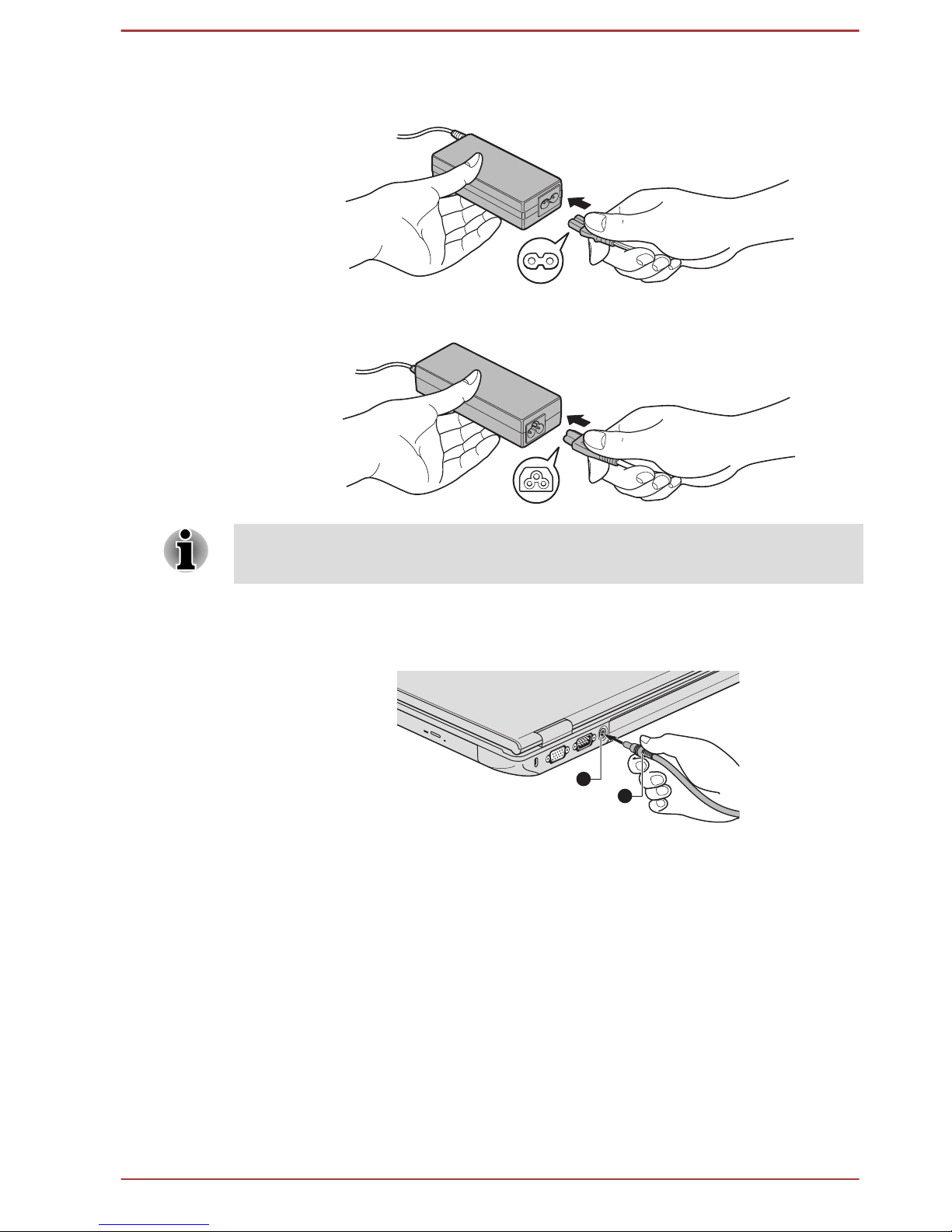
1. Connect the power cord to the AC adaptor.
Figure 1-1 Connecting the power cord to the AC adaptor (2-pin plug)
Figure 1-2 Connecting the power cord to the AC adaptor (3-pin plug)
Either a 2-pin or 3-pin adaptor/cord will be included with the computer
depending on the model.
2. Connect the AC adaptor’s DC output plug to the DC IN 15V jack on
the back of the computer.
Figure 1-3 Connecting the DC output plug to the computer
1
2
1. DC IN 15V jack
2. DC output plug
3. Plug the power cord into a live wall outlet - the Battery and DC IN
indicators on the front of the computer should glow.
Opening the display
The display panel can be opened to a wide range of angles for optimal
viewing.
While holding down the palm rest with one hand so that the main body of
the computer is not raised, slowly lift the display panel - this will allow the
angle of the display panel to be adjusted to provide optimum clarity.
User's Manual
1-4
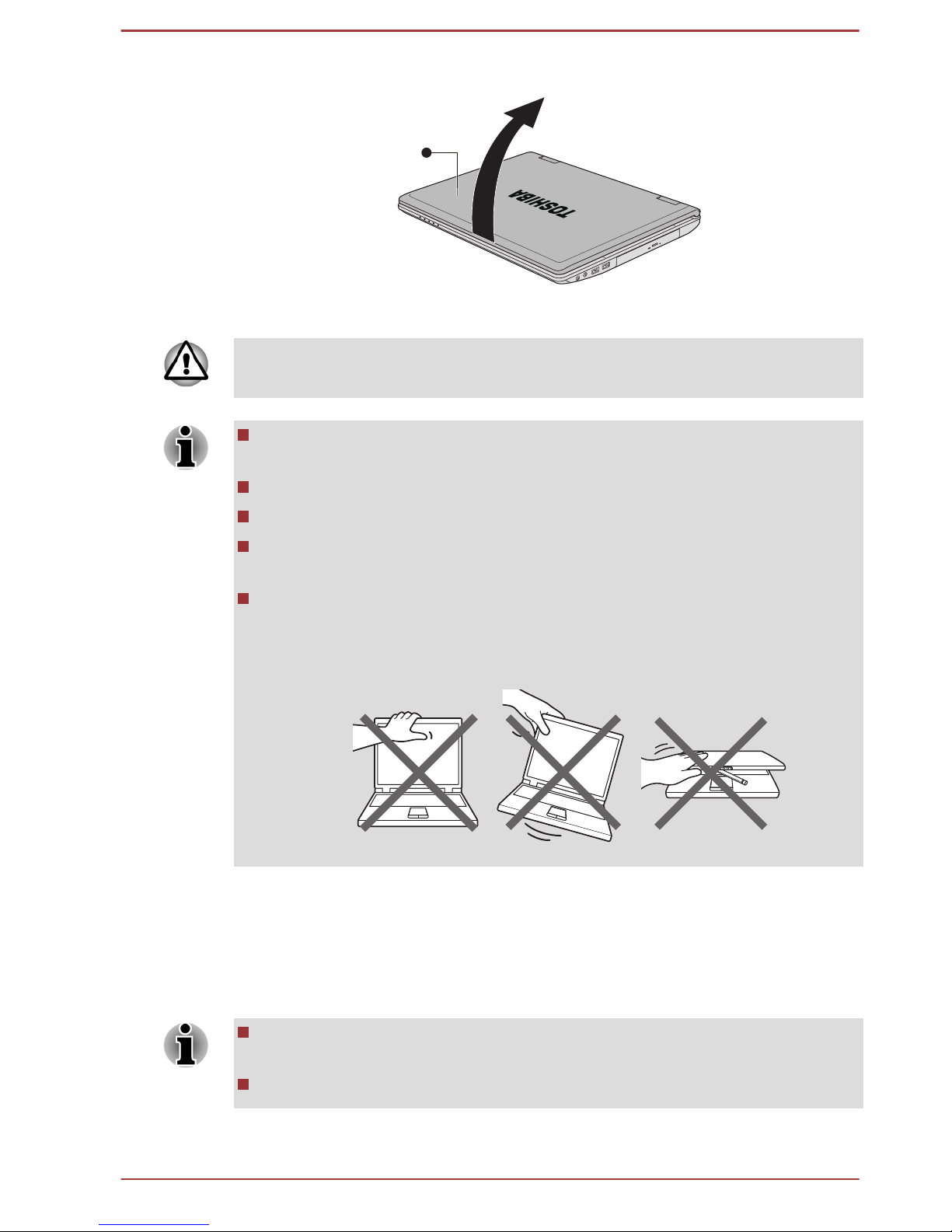
Figure 1-4 Opening the display panel
1
1. Display panel
Use reasonable care when opening and closing the display panel. Opening
it vigorously or slamming it shut could damage the computer.
Be careful not to open the display panel too far as this could put stress
on the display panel’s hinges and cause damage.
Do not press or push on the display panel.
Do not lift the computer by the display panel.
Do not close the display panel with pens or any other objects left in
between the display panel and the keyboard.
When opening or closing the display panel, place one hand on the
palm rest to hold the computer in place and use the other hand to
slowly open or close the display panel (Do not use excessive force
when opening or closing the display panel).
Turning on the power
This section describes how to turn on the power - the Power indicator will
then indicate the status. Please refer to the Monitoring of power condition
section in Chapter 5, Power and Power-Up Modes for more information.
After you turn on the power for the first time, do not turn it off until you
have set up the operating system.
Volume cannot be adjusted during Windows Setup.
1. Open the display panel.
User's Manual
1-5
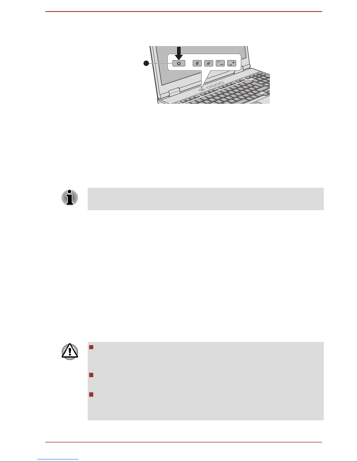
2. Press and hold the computer's power button for two or three seconds.
Figure 1-5 Turning on the power
1
1. Power button
Product appearance depends on the model you purchased.
Starting up for the first time
The Windows 7 Startup Screen will be the first screen displayed when you
turn on the power. Follow the on-screen instructions on each screen in
order to properly install the operating system.
When it is displayed, be sure to read the Software License Terms
carefully.
Turning off the power
The power can be turned off in one of three modes, either Shut Down
Mode, Hibernation Mode or Sleep Mode.
Shut Down Mode
When you turn off the power in Shut Down Mode no data will be saved and
the computer will boot to the operating system's main screen the next time
it is turned on.
1. If you have entered data, either save it to the hard disk drive or to
other storage media.
2. Make sure all disk/disc activity has stopped before removing the disk/
disc.
Make sure the Hard Disk Drive/Optical Disc Drive/eSATA indicator
is off. If you turn off the power while a disk (disc) is being accessed,
you may lose data or damage the disk.
Never turn off the power while an application is running. Doing so
could cause loss of data.
Never turn off the power, disconnect an external storage device or
remove storage media during data read/write. Doing so can cause
data loss.
3. Click Start.
User's Manual
1-6
4.
Click the Shut down button (
).
5. Turn off any peripheral devices connected to your computer.
Do not turn the computer or peripheral devices back on immediately - wait
a short period to avoid any potential damage.
Sleep Mode
If you have to interrupt your work, you are able to turn off the power without
exiting from your software by placing the computer into Sleep Mode. In this
mode data is maintained in the computer's main memory so that when you
turn on the power again, you can continue working right where you left off.
When you have to turn off your computer aboard an aircraft or in places
where electronic devices are regulated or controlled, always completely
shut down the computer. This includes turning off any wireless
communication functionalities, and cancelling settings that reactivate the
computer automatically, such as a timer recording function. Failure to
completely shut down the computer in this way could allow the operating
system to reactivate and run pre-programmed tasks or preserve unsaved
data, which could interfere with aviation or other systems, possibly causing
serious injury.
Before entering Sleep Mode, be sure to save your data.
Do not install or remove a memory module while the computer is in
Sleep Mode. The computer or the memory module could be damaged.
Do not remove the battery pack while the computer is in Sleep Mode
(unless the computer is connected to an AC power source). Data in
memory could be lost.
Do not switch to Sleep Mode while transferring data to external media,
such as USB devices, memory media or other external memory
devices. Data will be lost.
When the AC adaptor is connected, the computer will go into Sleep
Mode according to the settings in the Power Options (to access it,
Start -> Control Panel -> System and Security -> Power Options).
To restore the operation of the computer from Sleep Mode, press and
hold the power button or any key on the keyboard for a short amount
of time. Please note that keyboard keys can only be used if the Wakeup on Keyboard option is enabled within the HWSetup utility.
If the computer enters Sleep Mode while a network application is
active, the application might not be restored when the computer is
next turned on and the system returns from Sleep Mode.
User's Manual 1-7

To prevent the computer from automatically entering Sleep Mode,
disable Sleep Mode within the Power Options (to access it, Start ->
Control Panel -> System and Security -> Power Options).
To use the Hybrid Sleep function, configure it in the Power Options.
Benefits of Sleep Mode
The Sleep Mode feature provides the following benefits:
Restores the previous working environment more rapidly than does
the Hibernation Mode feature.
Saves power by shutting down the system when the computer
receives no input or hardware access for the time period set by the
System Sleep Mode feature.
Allows the use of the panel power off feature.
Executing Sleep Mode
You can also enable Sleep Mode by pressing FN + F3 - please refer to the
Hot key functions section in Chapter 3, Operating Basics, for further details.
You can enter Sleep Mode in one of three ways:
Click Start, point to the arrow icon ( ) and then select Sleep
from the menu.
Close the display panel. Please note that this feature must be enabled
within the Power Options (to access it, click Start -> Control Panel ->
System and Security -> Power Options).
Press the power button. Please note that this feature must be enabled
within the Power Options (to access it, click Start -> Control Panel ->
System and Security -> Power Options).
When you turn the power back on, you can continue where you left when
you shut down the computer.
When the computer is in Sleep Mode, the power indicator will blink
orange.
If you are operating the computer on battery power, you can lengthen
the overall operating time by turning it off into Hibernation Mode Sleep Mode will consume more power while the computer is off.
Sleep Mode limitations
Sleep Mode will not function under the following conditions:
Power is turned back on immediately after shutting down.
Memory circuits are exposed to static electricity or electrical noise.
User's Manual
1-8

Hibernation Mode
The Hibernation Mode feature saves the contents of memory to the hard
disk drive when the computer is turned off so that, the next time it is turned
on, the previous state is restored. Please note that the Hibernation Mode
feature does not save the status of any peripheral devices connected to the
computer.
Save your data. While entering Hibernation Mode, the computer saves
the contents of memory to the hard disk drive. However, for safety
sake, it is best to save your data manually.
Data will be lost if you remove the battery or disconnect the AC
adaptor before the save is completed. Wait for the Hard Disk Drive/
Optical Disc Drive/eSATA indicator to go out.
Do not install or remove a memory module while the computer is in
Hibernation Mode. Data will be lost.
Do not switch to Hibernation Mode while transferring data to external
media, such as USB devices, memory media or other external
memory devices. Data will be lost.
Benefits of Hibernation Mode
The Hibernation Mode feature provides the following benefits:
Saves data to the hard disk drive when the computer automatically
shuts down because of a low battery condition.
You can return to your previous working environment immediately
when you turn on the computer.
Saves power by shutting down the system when the computer
receives no input or hardware access for the time period set by the
System Hibernate feature.
Allows the use of the panel power off feature.
Starting Hibernation Mode
You can also enable Hibernation Mode by pressing FN + F4 - please refer
to the Hot key functions section in Chapter 3, Operating Basics, for further
details.
To enter Hibernation Mode, follow the steps below.
1. Click Start.
2.
Point to the arrow icon (
) and then select Hibernate from the
menu.
User's Manual
1-9

Automatic Hibernation Mode
The computer can be configured to enter Hibernation Mode automatically
when you press the power button or close the lid. In order to define these
settings, you can follow the steps as described below:
1. Click Start and click the Control Panel.
2. Click System and Security and click Power Options.
3. Click Choose what the power button does or Choose what
closing the lid does.
4. Enable the desired Hibernation Mode settings for When I press the
power button and When I close the lid.
5. Click the Save changes button.
Data save in Hibernation Mode
When you turn off the power in Hibernation Mode, the computer will take a
moment to save the current data in memory to the hard disk drive. During
this time, the Hard Disk Drive/Optical Disc Drive/eSATA indicator will
glow.
After you turn off the computer, and the content of memory has been saved
to the hard disk drive, turn off the power to any peripheral devices.
Do not turn the computer or devices back on immediately. Wait a moment
to let all capacitors fully discharge.
Restarting the computer
Certain conditions require that you reset the computer, for example if:
You change certain computer settings.
An error occurs and the computer does not respond to your keyboard
commands.
If you need to restart the computer, there are three ways this can be
achieved:
Click Start, point to the arrow icon ( ) and then select Restart
from the menu.
Press CTRL, ALT and DEL simultaneously (once) to display the menu
window, then select Restart from the Shut down options.
Press the power button and hold it down for five seconds. Once the
computer has turned itself off, wait between ten and fifteen seconds
before turning the power on again by pressing the power button.
User's Manual
1-10

Chapter 2
The Grand Tour
This chapter identifies the various components of the computer - it is
recommended that you become familiar with each before you operate the
computer.
Legal Footnote (Non-applicable Icons)
For more information regarding Non-applicable Icons, please refer to the
Legal Footnotes section in Appendix C.
Please handle your computer carefully to avoid scratching or damaging the
surface.
Front with the display closed
The following figure shows the computer’s front with its display panel in the
closed position.
Figure 2-1 Front of the computer with display panel closed
1 2 3 4 5
10
10
86
7
9
1. DC IN indicator
6. Memory media slot
2. Power indicator 7. Wireless communication indicator*
3. Battery indicator 8. Wireless WAN indicator*
4. Hard Disk Drive/Optical Disc Drive/
eSATA indicator
9. Microphone
5. Memory media slot indicator 10. Stereo speakers
* Provided with some models.
Product appearance depends on the model you purchased.
User's Manual
2-1

DC IN indicator The DC IN indicator normally glows green when
power is being correctly supplied from the AC
power adaptor. However, if the output voltage
from the adaptor is abnormal, or if the computer's
power supply malfunctions, this indicator will
flash orange.
Power indicator The Power indicator normally glows green when
the computer is turned on. However, if you turn
the computer off into Sleep Mode, this indicator
will flash orange - approximately two seconds on,
two seconds off.
Battery indicator The Battery indicator shows the condition of the
battery's charge - green indicates the battery is
fully charged, orange indicates the battery is
charging, and flashing orange indicates a low
battery condition.
Please refer to Chapter 5, Power and Power-Up
Modes for more information on this feature.
Hard Disk Drive/
Optical Disc Drive/
eSATA indicator
The Hard Disk Drive/Optical Disc Drive/
eSATA indicator blinks green whenever the
computer is accessing the built-in hard disk drive,
optical disc drive or eSATA device.
Memory media slot
indicator
The Memory media slot indicator blinks green
when the computer is accessing the memory
media slot.
Memory media slot This slot lets you insert an SD™/SDHC™/
SDXC™ memory card, miniSD™/microSD™
Card, Memory Stick™ (PRO™/Duo™/PRO
Duo™/Micro™), xD-Picture Card™ and
MultiMediaCard™. Refer to the Optional devices
section in Chapter 3, Operating Basics for more
information.
Wireless
communication
indicator
The Wireless communication indicator glows
orange when the Wireless functions are turned
on.
Some models are equipped with Wireless
functions.
Wireless WAN
indicator
This indicator always show off with no effect.
User's Manual 2-2

Microphone A built-in microphone allows you to import and
record sounds for your application - please refer
to the Sound System section in Chapter 3,
Operating Basics for more information.
Stereo speakers The speakers emit sound generated by your
software as well as audio alarms, such as low
battery condition, generated by the system.
Left side
The following figure shows the computer’s left side.
Figure 2-2 The left side of the computer
1 2 3 4 5
6
1. Universal Serial Bus (USB 3.0) port 4. Mini DisplayPort*
2. eSATA/USB combo port 5. ExpressCard slot or PC Card slot*
3. Cooling vents 6. PC Card eject button
* Provided with some models.
Product appearance depends on the model you purchased.
Universal Serial Bus
(USB 3.0) port
One Universal Serial Bus port, which complies to
the USB 3.0 standard, is provided on the left side
of the computer.
The USB 3.0 port is compliant with USB 3.0
standard and backward compatible with USB 2.0
devices.
eSATA/USB combo
port
One eSATA/USB combo port, which complies to
the USB 2.0 standard, is provided on the left side
of the computer.
This port with the icon ( ) supports the following
functions:
USB Sleep and Charge function
System ON CDP Charge Mode
Cooling vents The cooling vents help the processor to avoid
overheating.
Do not block the cooling vents. Keep foreign metal objects, such as
screws, staples and paper clips, out of the cooling vents. Foreign metal
User's Manual 2-3

objects can create a short circuit, which can cause damage and fire,
possibly resulting in serious injury.
Mini DisplayPort This port is capable of driving resolutions up to
2560x1600. With a suitable adapter, Mini
DisplayPort may be used to drive displays with a
HDMI or DVI interface.
Some models are equipped with a Mini
DisplayPort.
ExpressCard slot This slot allows you to install a single
ExpressCard device.
PC Card slot This slot can accommodate a single Type II, 16-
bit or 32-bit (CardBus) PC Card device.
PC Card eject button This button is used in order to remove a PC Card
from within the computer.
Right side
The following figure shows the computer’s right side.
Figure 2-3 The right side of the computer
1 2
354
1. Headphone jack 4. Universal Serial Bus (USB 2.0) port
2. Microphone jack 5. Optical disc drive*
3. Universal Serial Bus (USB 2.0) port
* Provided with some models.
Product appearance depends on the model you purchased.
Headphone jack A 3.5 mm mini headphone jack enables
connection of stereo headphones.
Microphone jack A 3.5 mm mini microphone jack enables
connection of a three-conductor mini jack for
monaural microphone input.
Universal Serial Bus
(USB 2.0) ports
Two Universal Serial Bus ports, which comply to
the USB 2.0 standard, are provided on the right
side of the computer.
Optical disc drive The computer may be configured with an optical
disc drive.
User's Manual 2-4

2.6GB and 5.2GB DVD-RAM media cannot be read from or written to.
Please note that it is not possible to confirm the operation of all functions of
all USB devices that are available. In view of this it may be noted that some
functions associated with a specific device might not operate properly.
USB 3.0 port(s) may work as USB 2.0 port(s) when operating in USB
Legacy Emulation mode.
Keep foreign metal objects, such as screws, staples and paper clips, out of
the Memory media slot, ExpressCard/PC Card slot, eSATA/USB combo
port and USB port. Foreign metal objects can create a short circuit, which
can cause damage and fire, possibly resulting in serious injury.
Back
The following figure shows the computer’s back.
Figure 2-4 The back of the computer
1 2 3 4 5 6
87
1. Security lock slot 5. Modem jack*
2. External RGB monitor port 6. LAN jack
3. Serial port* 7. LAN active indicator (orange)
4. DC IN 15V jack 8. Link indicator (green)
* Provided with some models.
Product appearance depends on the model you purchased.
Security lock slot A security cable can be attached to this slot and
then connected to a desk or other large object in
order to deter theft of the computer.
External RGB monitor
port
This port provides 15-pin, analog RGB port.
This port allows you to connect an external RGB
monitor to the computer.
Serial port Use this 9-pin port to connect serial devices such
as an external modem, serial mouse or serial
printer.
Some models are equipped with a serial port.
User's Manual 2-5

DC IN 15V jack The AC adaptor connects to this jack in order to
power the computer and charge its internal
batteries. Please note that you should only use
the model of AC adaptor supplied with the
computer at the time of purchase - using the
wrong AC adaptor can cause damage to the
computer.
Modem jack The modem jack lets you use a modular cable to
connect the modem directly to a telephone line.
Some models are equipped with a modem jack.
LAN jack This jack lets you connect to a LAN. The adaptor
has built-in support for Ethernet LAN (10
megabits per second, 10BASE-T), Fast Ethernet
LAN (100 megabits per second, 100BASE-TX) or
Gigabit Ethernet LAN (1000 megabits per
second, 1000BASE-T). Refer to chapter 3,
Operating Basics, for details.
Do not connect any cable other than a LAN cable to the LAN jack. It
could cause damage or malfunction.
Do not connect the LAN cable to a power supply. It could cause
damage or malfunction.
LAN active indicator
(orange)
This indicator may glow orange when the
computer is connected to a LAN and the LAN is
functioning properly.
Link indicator (green) This indicator may glow green when the
computer is connected to a LAN and the LAN is
functioning properly.
Underside
The following figure shows the underside of the computer. You should
ensure that the display is closed before the computer is turned over to
avoid causing any damage.
User's Manual
2-6

Figure 2-5 The underside of the computer
231
4
1. Battery lock 3. Battery pack
2. Battery release latch 4. Memory module slot
Product appearance depends on the model you purchased.
Battery lock Slide the battery lock to release the battery pack
ready for removal.
Battery release latch Slide and hold this latch into its "Unlock" position
in order to release the battery pack for removal.
For more detailed information on removing the
battery pack please refer to Chapter 5, Power
and Power-Up Modes.
Battery pack The rechargeable lithium-ion battery pack
provides power to the computer when the AC
adaptor is not connected. For more detailed
information on the use and operation of the
battery pack please refer to Chapter 5, Power
and Power-Up Modes.
Legal Footnote (Battery Life)
For more information regarding Battery Life, please refer to the Legal
Footnotes section in Appendix C.
Memory module slot The memory module slot allows the installation,
replacement and removal of additional memory
module.
The size of the memory modules varies
depending on the model. The actual amount of
useable system memory may be less than the
installed memory modules.
Refer to the Additional memory module section in
Chapter 3, Operating Basics.
User's Manual 2-7

Legal Footnote (Memory (Main System))
For more information regarding Memory (Main System), please refer to the
Legal Footnotes section in Appendix C.
Front with the display open
This section shows the computer with the display panel open. In order to
open the display, lift the display panel up and position it at a comfortable
viewing angle for you.
Figure 2-6 The front of the computer with the display panel open
6
5
7
8
9
10
11
13
15
14
14
4
2
1
3
6
12
1. Wireless communication antennas
(not shown)*
9. TOSHIBA Presentation button
2. Web Camera LED* 10. Volume down button
3. Web Camera* 11. Volume up button
4. Display screen 12. Keyboard
5. LCD Sensor switch (not shown) 13. Touch Pad
6. Display hinges 14. Touch Pad control buttons
7. Power button 15. Fingerprint Sensor*
8. TOSHIBA eco button
* Provided with some models.
Product appearance depends on the model you purchased.
Wireless
communication
antennas
Some computers in this series are equipped with
the Wireless LAN/Bluetooth antennas.
Legal Footnote (Wireless LAN)
For more information regarding Wireless LAN, please refer to the Legal
Footnotes section in Appendix C.
User's Manual 2-8

Web Camera LED The Web Camera LED glows when the Web
Camera is operating.
Web Camera Web Camera is a device that allows you to
record video or take photographs with your
computer. You can use it for video chatting or
video conferences using a communication tool
such as Windows Live Messenger. TOSHIBA
Web Camera Application will help you to add
various video effects to your video or photograph.
Enables the transmission of video and use of
video chat via the internet using specialized
applications.
Please refer to the Web Camera Application
Online Help for details.
Do not point the web camera directly at the sun.
Do not touch or press strongly on the web camera lens. Doing so may
reduce image quality. Use an eyeglass cleaner (cleaner cloth) or other
soft cloth to clean the lens if it becomes dirty.
When recording in dimly lit environments, select "Night Mode" which
allows for brighter images with less noise.
Display screen 39.6cm (15.6") LCD screen, 16 million colors,
configured with the following resolution:
HD+, 1600 horizontal x 900 vertical pixels
HD, 1366 horizontal x 768 vertical pixels
Please be aware that, when the computer is
operating on the AC adaptor, the image
displayed on the internal screen will be
somewhat brighter than when it operates on
battery power. This difference in brightness
levels is intended to save power when operating
on batteries.
Legal Footnote (LCD)
For more information regarding LCD, please refer to the Legal Footnotes
section in Appendix C.
User's Manual 2-9

LCD Sensor switch This switch senses when the display panel is
either closed or opened and activates the Panel
Power Off/On feature as appropriate. For
example, when you close the display panel the
computer enters Hibernation Mode and shuts
itself down and then, when you next open the
display, the computer will automatically start up
and return you to the application you were
previously working on.
You can specify within the Power Options. To
access it, click Start -> Control Panel ->
System and Security -> Power Options.
Do not put any magnetic objects close to this switch as they may cause the
computer to automatically enter Hibernation Mode and shut down even if
the Panel Power Off feature is disabled.
Display hinges The display hinges allow the display panel to be
positioned at a variety of easy-to-view angles.
Power button Press this button to turn the computer's power on
or off.
TOSHIBA eco button Press this button to launch the TOSHIBA eco
Utility. TOSHIBA eco Utility can be used only in
Windows® 7.
TOSHIBA
Presentation button
The TOSHIBA Presentation button has the same
functionality as the Connect display button in the
Mobility Center.
volume down button Press this button to decrease the volume.
volume up button Press this button to increase the volume.
Keyboard Your computer may intergrated with two kinds of
keyboards: A4 size keyboard which provides the
embedded numeric overlay keys, dedicated
cursor control overlay keys, and Keys; full
size keyboard which provides dedicated numeric
keys, dedicated cursor control keys, and
Keys. Refer to the The Keyboard section in
Chapter 3, Operating Basics, for details.
User's Manual 2-10

Touch Pad The Touch Pad located in the palm rest is used
to control the movement of the on-screen pointer.
For more information, please refer to the Using
the Touch Pad in Chapter 3, Operating Basics.
Touch Pad control
buttons
The control buttons located below the Touch Pad
allow you to select menu items or manipulate text
and graphics as designated by the on-screen
pointer.
Fingerprint Sensor This sensor enables you to enroll and recognize
a fingerprint. For detailed information on
Fingerprint Sensor, refer to the Using the
Fingerprint Sensor section in Chapter 3,
Operating Basics.
Some models are equipped with a Fingerprint
Sensor.
Internal Hardware Components
This section describes the internal hardware components of your computer.
The actual specifications may vary depending on the model you
purchased.
CPU The processor type varies depending on model.
To check which type of processor is included in
your model, open the TOSHIBA PC Diagnostic
Tool Utility by clicking Start -> All Programs ->
TOSHIBA -> Support & Recovery -> PC
Diagnostic Tool.
Legal Footnote (CPU)
For more information regarding CPU, please refer to the Legal Footnotes
section in Appendix C.
Hard Disk Drive or
Solid State Drive
The size of the hard disk drive varies depending
on the model.
To check which type of HDD/SSD is included in
your model, open the TOSHIBA PC Diagnostic
Tool Utility by clicking Start -> All Programs ->
TOSHIBA -> Support & Recovery -> PC
Diagnostic Tool.
Please note that part of the hard disk's overall
capacity is reserved as administration space.
In this manual, the word "HDD" or "Hard disk drive" also refers to the
SSD unless otherwise stated.
User's Manual 2-11

SSD is a large-capacity storage media which uses Solid-State
Memory in place of a magnetic disk of the hard disk.
Under certain unusual conditions of prolonged non-use and/or exposure to
high temperatures, the SSD may be vulnerable to data retention errors.
Legal Footnote (Hard Disk Drive (HDD) Capacity)
For more information regarding Hard Disk Drive (HDD) Capacity, please
refer to the Legal Footnotes section in Appendix C.
RTC battery The internal RTC battery backs up the Real Time
Clock (RTC) and calendar.
Video RAM The memory in a computer's graphics adaptor,
used to store the image displayed on a bitmap
display.
The amount of Video RAM available is
dependent on the computer's system memory.
Start -> Control Panel -> Appearance and
Personalization -> Display -> Adjust
resolution.
The amount of Video RAM can be verified by
clicking the Advanced settings button in the
Screen Resolution window.
Display controller The display controller interprets software
commands into hardware commands that turn
particular parts on the screen on or off.
The display controller also controls the video
mode and uses industry standard rules to govern
the screen resolution and the maximum number
of colors that can be displayed at a time.
Therefore, software written for a given video
mode will run on any computer that supports that
mode.
Due to the display panel's increased resolution, lines may appear broken in
when displaying images in full-screen text mode.
Graphics controller The graphics controller maximizes display
performance.
Legal Footnote (Graphics Processing Unit (GPU))
User's Manual 2-12

For more information regarding Graphics Processing Unit (GPU), please
refer to the Legal Footnotes section in Appendix C.
Intel Rapid Start Technology
Some computers in this series support Intel® Rapid Start Technology which
enables the computer to change to Hibernation Mode from Sleep Mode
after a specified period of time.
With the Intel® Rapid Start Technology, the Windows can rapidly resume
from Hibernation Mode and battery life will be longer than when in Sleep
Mode.
Intel® Rapid Start Technology is enabled at factory default. The computer
will switch to Hibernation Mode after two hours of Sleep Mode.
You can use BIOS Setup to enable/disable the function and change the
specified time setting from Sleep Mode to Hibernation Mode.
1. Press and hold the F2 key, and then turn on the computer - the BIOS
setup utility will load.
2. Select Advanced.
3. Enable/Disable Intel(R) Rapid Start Technology function.
4. You can select the period of time from Sleep Mode to Hibernation
Mode using Rapid Start Entry after. If the Immediately option is
selected, the computer will switch to Hibernation Mode immediately
after your computer goes into the Sleep Mode.
When Intel
®
Rapid Start Technology is enabled, switching from Sleep
Mode to Hibernation Mode consumes power. When you carry your
computer aboard on an aircraft or in places where electronic devices
are regulated or controlled, always power off your computer.
When Intel® Rapid Start Technology is enabled, Wake-up on LAN,
Wake-up on USB or Wake-up from Sleep Mode automatically
functions are not available when the computer has been switched from
Sleep Mode to Hibernation Mode.
The Windows cannot be restored normally if the battery is exhausted
when the computer is moving from Sleep Mode to Hibernation Mode.
The partition allocation on the Hard Disk Drive for the Intel® Rapid
Start Technology cannot be deleted even if Intel® Rapid Start
Technology is disabled.
Intel® Rapid Start Technology can be used only for Windows 7.
Intel® Rapid Start Technology cannot be used in models that do not
equipped with a Solid State Drive.
The Windows restore time from Hibernation Mode depends on the
amount of system memory used in the computer.
User's Manual 2-13

After an additional memory module is installed, the computer may not
switch to Hibernation Mode normally by using Intel® Rapid Start
Technology. In this case, you can restore the system to factory default
to re-enable Intel® Rapid Start Technology.
User's Manual 2-14

Chapter 3
Operating Basics
This chapter describes the basic operations of your computer, highlights
the precautions that should be taken when using it.
Using the Touch Pad
To use the Touch Pad, simply touch and move your fingertip across it in
the direction you want the on-screen pointer to go.
Figure 3-1 Touch Pad and Touch Pad control buttons
1
2
3
3
1. Touch Pad 3. Touch Pad control buttons
2. Fingerprint Sensor*
* Provided with some models.
The two buttons below the Touch Pad are used like the buttons on a
standard mouse - press the left button to select a menu item or to
manipulate text or graphics designated by the pointer, and press the right
button to display a menu or other function depending on the software you
are using.
The Keyboard
The computer’s keyboard layouts are compatible with a 104/105-key
enhanced keyboard - by pressing some keys in combination, all of the
104/105-key enhanced keyboard functions can be performed on the
computer.
The number of keys available on your keyboard will depend on which
country/region your computer is configured for, with keyboards being
available for numerous languages.
In use there are six different types of keys, specifically typewriter keys,
function keys, soft keys, Hot keys, Windows special keys and the keypad
overlay.
User's Manual
3-1

Never remove the key caps on your keyboard. Doing so could cause
damage to the parts under the key caps.
Keyboard indicators
A4 size keyboard
The following figures show the positions of the CAPS LOCK indicator and
the keypad overlay indicators which show the following conditions:
When the CAPS LOCK indicator glows, the keyboard will produce
capitals when any letter is typed.
When the Arrow Mode indicator glows, the keypad overlay allows you
to use cursor functions.
When the Numeric Mode indicator glows, the keypad overlay allows
you to enter numbers.
Figure 3-2 CAPS LOCK indicator
1
1. CAPS LOCK indicator
CAPS LOCK This indicator glows green when letter keys are
locked into their uppercase format.
Figure 3-3 Keypad overlay indicators
1
2
1.
Arrow mode indicator 2. Numeric mode indicator
User's Manual 3-2

Arrow mode When the Arrow mode indicator lights green,
you can use the gray labeled keys on the keypad
overlay as cursor keys. Please refer to the
Keypad overlay for A4 size keyboard section for
more information.
Numeric mode When the Numeric mode indicator lights green,
you can use the gray labeled keys on the keypad
overlay for number entry. Please refer to the
Keypad overlay for A4 size keyboard section for
more information.
Full size keyboard
The following figures show the positions of the CAPS LOCK indicator and
the NUM LOCK indicators which show the following conditions:
When the CAPS LOCK indicator glows, the keyboard will produce
capitals when any letter is typed.
When the NUM LOCK indicator glows, the ten key allows you to enter
numbers.
Figure 3-4 Keypad indicators
2
1
1. CAPS LOCK indicator 2. NUM LOCK indicator
CAPS LOCK This indicator glows green when letter keys are
locked into their uppercase format.
NUM LOCK When the NUM LOCK indicator glows, you can
use the number keys on the keyboard for number
entry.
Function keys: F1 … F12
The function keys (not to be confused with the special FN key) are the
twelve keys at the top of your keyboard - these keys function differently
from other keys.
User's Manual
3-3

F1 through F12 are called function keys because they execute
programmed functions when pressed and, when used in combination with
the FN key, those keys marked with icons also execute specific functions
on the computer.
Soft keys: FN key combinations
The FN (function) is used in combination with other keys to form soft keys.
Soft keys are key combinations that enable, disable or configure specific
features.
Please note that some software may disable or interfere with soft-key
operations, and that the soft-key settings are not restored when the
computer returns from Sleep Mode.
This computer's keyboard is designed to provide all the features of the 104key enhanced keyboard.
Since the keyboard is smaller and has fewer keys, some of the enhanced
keyboard functions must be simulated using two keys instead of one on the
larger keyboard.
The FN key can be combined with the following keys to simulate functions
similar to those of keys on the 104/105 key enhanced keyboard which are
not on this computer's keyboard.
For A4 size keyboard:
Press FN + F10 or FN + F11 to access the computer's integrated
keypad. When activated, the keys with grey markings on their bottom
edge become either numeric keypad keys (FN + F11) or cursor control
keys (FN + F10).
Press FN + F12 (ScrLock) to lock the cursor on a specific line. The
power on default is off.
Press FN + ENTER to simulate ENTER on the enhanced keyboard’s
numeric keypad.
Hot key functions
Hot key functions let you enable or disable certain features of the
computer. The Hot key functions can be performed using either the Hot
Key Cards or by pressing the associated Hot keys (pressing FN + a
function or ESC key).
Hot Key Cards
The Hot Key Cards are normally hidden from view. The Cards appear
when you press the FN key.
To use the Hot Key Cards:
1. Press and hold the FN key. The TOSHIBA Flash Cards appear along
the top of the screen.
User's Manual
3-4

2. Select the desired option.
The selected Card is displayed full-size with its available options
below it. All other Cards are again hidden from view.
3. Click the desired option.
To use a Hot Key Card using a hot key:
1. Press and hold the FN key.
2. Press the hot key associated with the desired function. The associated
hot key card appears at the top of the screen with its available options
below it.
3. To cycle through the displayed options, hold down FN and press the
hot key repeatedly. Release the FN key when the desired option is
selected.
For more information, please refer to the TOSHIBA Flash Cards Help file.
To access this help, click Start -> All Programs -> TOSHIBA -> Tools &
Utilities -> Flash Cards. In the Settings for Flash Cards window, click
the Help button.
Hot keys
This section describes the associated functions of the hot keys.
Mute
Pressing FN + ESC turns the volume on and off.
Lock
Pressing FN + F1 enters ''Lock computer mode''. To restore your
desktop, you need to log on again.
Power Plan
Pressing FN + F2 changes the power settings.
Sleep
Pressing FN + F3 switches the system to Sleep Mode.
Hibernate
Pressing FN + F4 switches the system to Hibernation Mode.
Output
Pressing FN + F5 changes the active display device.
To use a simultaneous mode, you must set the resolution of the internal
display panel to match the resolution of the external display device.
Brightness Down
Pressing FN + F6 decreases the computer's display panel brightness
in individual steps.
Brightness Up
Pressing FN + F7 increases the computer's display panel brightness in
individual steps.
Wireless
Pressing FN + F8 switches the active wireless devices.
User's Manual
3-5

If no wireless communication device is installed, no dialog box will appear.
Touch Pad
Pressing FN + F9 enables or disables the Touch Pad function.
Zoom (Display resolution)
Pressing FN + Space changes the display resolution.
ODD
Pressing FN + TAB ejects the disc tray.
Reduce
Pressing FN + 1 reduces the icon size on the desktop or the font sizes
within one of the supported application windows.
Enlarge
Pressing FN + 2 enlarges the icon size on the desktop or the font
sizes within one of the supported application windows.
FN Sticky key
You can use the TOSHIBA Accessibility Utility to make the FN key sticky,
that is, you can press it once, release it, and then press an "F Number"
key. To start the TOSHIBA Accessibility utility, click Start -> All Programs
-> TOSHIBA -> Tools & Utilities -> Accessibility.
Windows special keys
The keyboard provides two keys that have special functions in Windows,
the Windows Start Button key activates the Start menu while the
application key has the same function as the secondary (right) mouse
button.
This key activates the Windows Start menu.
This key has the same function as the secondary (right) mouse button.
Keypad overlay for A4 size keyboard
Your computer's keyboard may not have a separate numeric keypad but
includes a numeric keypad overlay which functions like one - this is located
in the center of the keyboard with the relevant keys having grey letters at
their front edge. The overlay provides the same function as the numeric
keypad on a standard 104/105-key enhanced keyboard.
Turning on the overlays
The numeric keypad overlay can be used for numeric data input or cursor
and page control.
User's Manual
3-6

Arrow Mode
To turn on Arrow Mode, press FN + F10 - the Arrow Mode indicator lights
and you are able to access cursor and page control functions by using the
keys. You are able to press FN + F10 again to turn off this overlay function.
Numeric Mode
To turn on Numeric Mode, press FN + F11 - the Numeric Mode indicator
lights and you are able to access numeric characters by using the keys.
You are able to press FN + F11 again to turn off this overlay function.
Temporarily using normal keyboard (overlay on)
While using the overlay, you can temporarily access the normal keyboard
functions without having to turn the overlay off:
1. Hold down FN key and press any other key - this key will operate as if
the overlay were off.
2. Type upper-case characters by holding down FN + SHIFT and
pressing a character key.
3. Release FN key to continue using the selected overlay function.
Temporarily using overlay (overlay off)
While using the normal keyboard function, you can temporarily use the
keypad overlay without having to turn it on:
1. Hold down FN key.
2. Check the keyboard indicators as pressing the FN key will turn on the
most recently used overlay function - if the Numeric Mode indicator
lights you can use the overlay for numeric entry, while if the Arrow
Mode indicator lights, you can use the overlay for cursor and page
control function.
3. Release FN key to return to normal keyboard operation.
Temporarily changing modes
If the computer is in Numeric Mode, you can switch temporarily to Arrow
Mode by pressing a SHIFT key, while if it is in Arrow Mode, you can
switch temporarily to Numeric Mode by also pressing a SHIFT key.
Generating ASCII characters
Not all ASCII characters can be generated using normal keyboard
operation, but you are able to generate these characters using their
specific ASCII codes.
Full size keyboard:
1. Hold down ALT key.
2. Using the numeric keypad, type the ASCII code of the character you
require.
3. Release ALT - the ASCII character will appear on the display screen.
User's Manual
3-7

A4 size keyboard:
1. Hold down ALT with the overlay on or ALT + FN with overlay off.
2. Using the overlay keys, type the ASCII code of the character you
require.
3. Release ALT or ALT + FN - the ASCII character will appear on the
display screen.
Using the Fingerprint Sensor
This product has a fingerprint utility installed for the purpose of enrolling
and recognizing fingerprints. By enrolling the ID and password onto the
fingerprint authentication feature, it is no longer necessary to input the
password from the keyboard. Fingerprint feature enables you to:
Logon to Windows and access a security enabled homepage through
Internet Explorer.
Files and folders can be encrypted/decrypted and third party access to
them prevented.
Unlock the password-protected screen-saver.
Authentication of the User Password (and, if applicable, the HDD
(Hard Disk Drive) Password) when booting up the computer (Pre-Boot
Authentication).
Single Sign-On feature
Fingerprint cannot be used in models that do not have a fingerprint module
installed.
How to Swipe your Finger
Using the following steps when swiping fingers for fingerprint registration or
authentication will help to minimize authentication failures:
Align the first joint of the finger to the center of the sensor. Lightly touch the
sensor and swipe finger levelly towards you until the sensor surface
becomes visible. In performing this process, you should also take care to
ensure that the center of your fingerprint is on the sensor.
The following illustrations show the recommended way to swipe your finger
over the fingerprint sensor.
Figure 3-5 Swipe the finger
1
1
1. Sensor
User's Manual 3-8

Avoid swiping with your finger stiff or pressed too hard onto the
sensor, and take care to ensure that the center of the fingerprint is
touching the sensor before swiping. Either of these conditions may
cause fingerprint reading to fail.
Check the center of the fingerprint whorl before swiping and then
ensure this is swiped along the center line of the sensor.
There is a possibility of authentication failures if the finger is swiped
too quickly or too slowly - follow any on-screen instructions to adjust
the speed used during the swipe process.
Points to note about the Fingerprint Sensor
Please be aware of the following considerations when using the fingerprint
sensor. A failure to follow these guidelines might result in damage to the
sensor, sensor failure, fingerprint recognition problems or a lower
fingerprint recognition success rate.
Do not scratch or poke the sensor with your nails or any hard or sharp
objects.
Do not press the sensor strongly.
Do not touch the sensor with a wet finger or any wet objects - keep the
sensor surface dry and free from water vapor.
Do not touch the sensor with a soiled or dirty finger as minute foreign
particles of dust and dirt may scratch it.
Do not paste stickers or write on the sensor.
Do not touch the sensor with a finger or any other object which may
have a build-up of static electricity on it.
Observe the following before you place your finger on the sensor whether
for fingerprint enrollment/registration or recognition.
Wash and dry your hands thoroughly.
Remove static electricity from your fingers by touching any metal
surface. Static electricity is a common cause of sensor failures,
especially when the weather is dry.
Clean the sensor with a lint-free cloth - do not use detergent or any
other chemicals to clean the sensor.
Avoid the following finger conditions for enrollment or recognition as
they may result in fingerprint enrollment errors or a drop in the
fingerprint recognition success rate
Soaked or swollen finger, for example as may occur after taking a
bath.
Injured finger
Wet finger
Soiled or oily finger
Extremely dry skin condition on finger
Observe the following to improve the fingerprint recognition success rate.
User's Manual
3-9

Enroll two or more fingers.
Enroll additional fingers if a recognition failure often occurs when using
already enrolled fingers.
Check the condition of your finger - any conditions which have
changed since enrollment, such as injury, rough skin, and extremely
dry, wet, soiled, dirty, oily, soaked or swollen fingers, may lower the
recognition success rate. Also if the fingerprint is worn down or the
finger becomes thinner or fatter, the recognition success rate may be
lowered.
As the fingerprint for each finger is different and unique you should
ensure that only the registered or enrolled fingerprint or fingerprints
are used for identification.
Check the position and speed at which you swipe your finger across
the sensor - please refer to the preceding drawing.
The fingerprint sensor compares and analyzes the unique
characteristics in a fingerprint. However, there may be instances
where certain users are unable to register their fingerprints due to
insufficient unique characteristics in their fingerprints.
The recognition success rate may differ from user to user.
Points to note about Fingerprint Utility
If Windows 7 file encryption function EFS (Encryption File System) is
used to encrypt a file, the file cannot be further encrypted using the
encryption function of this software.
You can back up the fingerprint data or the information registered to
Automatic password input in IE.
Please use Import/Export on TOSHIBA Fingerprint Utility main menu.
Please also refer to the fingerprint utility Help file for more information.
You can start it using the following method:
Click Start -> All Programs -> TOSHIBA -> Tools & Utilities ->
Fingerprint Utility. The main screen is displayed. Click ? in the lower
left corner of the screen.
Fingerprint utility limitations
TOSHIBA does not guarantee that the fingerprint utility technology will be
completely secure or error-free, or that it will accurately screen out
unauthorized users at all times. TOSHIBA is not liable for any failure or
damage that might arise out of the use of the fingerprint software.
Setup Fingerprint Registration
Please use the following procedure when first using fingerprint
authentication.
User's Manual
3-10

In use, the fingerprint authentication system will use the same
username and password as defined within the Windows operating
system. If no Windows password has been configured, you must do
this before starting the fingerprint registration process.
This sensor has the memory space for at least twenty fingerprint
patterns. You might be able to register more fingerprint patterns
depending on the sensor memory usage.
1. Click Start -> All Programs -> TOSHIBA -> Tools & Utilities ->
Fingerprint Utility, or click the Fingerprint utility icon in the Taskbar.
2. The Enroll screen is displayed. Enter the current account password
into the Windows Password field. If no Windows password has been
configured, you will be asked to configure the new logon password.
Then click Next.
3. Click the non-enrolled finger icon above the finger you want to register
and then click Next.
4. The note for enrollment operation screen is displayed. Confirm the
message and then click Next.
5. The scanning practice screen is displayed. You are able to practice
swiping (three times) your finger to ensure you use the correct
method. When you have finished practicing swiping your finger, click
Next.
6. Swipe three times with the same finger. If scanning of fingerprint
succeeds, "Enrollment successfully! Do you want to save this
fingerprint?" message box will appear. Click OK.
7. The following message will be displayed: "It’s strongly recommended
you enroll one more fingerprint.". Click OK and repeat Step 3, 4, 5 and
6 with another finger.
It is strongly recommended that you register 2 or more fingerprints.
You cannot enroll the same fingerprint more than once, even on a
different user account.
Delete the Fingerprint Data
Saved fingerprint data is stored in special non-volatile memory inside the
fingerprint sensor. Therefore, if you give the computer to someone else, or
dispose of it in any way, the following process is recommended to delete
your fingerprint information:
Delete the fingerprint data for the currently logged in user
1. Click Start -> All Programs -> TOSHIBA -> Tools & Utilities ->
Fingerprint Utility, or double click the utility icon in the Taskbar.
2. Swipe your finger across the fingerprint sensor.
User's Manual
3-11

3. The TOSHIBA Fingerprint Utility main menu is displayed. Select
Enroll in the main menu.
4. In the Enroll window, it enables you to delete the fingerprint data for
the currently logged in user. Click an enrolled finger you want to
delete. "Are you sure you want to delete this fingerprint template?"
message box will appear on the screen and then click OK. If you want
to delete other fingerprints, repeat this step. If only one fingerprint is
registered, the message "Sorry! At least one fingerprint is required."
will appear after clicking OK. You are not allowed to delete a unique
fingerprint.
5. Click Close.
6. "Are you sure you want to quit?" is displayed. Click OK. It will be
returned to the TOSHIBA Fingerprint Utility main menu.
Delete all users fingerprints
1. In the TOSHIBA Fingerprint Utility main menu, click Run as
administrator in the lower left.
2. User Account Control window is displayed. Click Yes.
3. Swipe your enrolled finger.
4. Select Fingerprint Control option.
5. A list of fingerprint information for all users is shown in the screen.
Click Delete All in the lower right.
6. "Are you sure you want to delete all fingerprints?" message box will
appear on the screen. Click OK.
7. Click Close.
8. "Are you sure you want to quit?" is displayed. Click OK. It will be
returned to the TOSHIBA Fingerprint Utility main menu.
Windows Logon via Fingerprint Authentication
In place of the usual Windows logon by ID and password, fingerprint
authentication also allows logon to Windows.
This is useful especially when many users are using the PCs, as user
selection can be skipped.
Fingerprint Authentication Procedure
1. Start up the computer.
2. The Logon Authorization screen is displayed. Choose any of the
enrolled fingers and swipe the fingerprint on the sensor. If
authentication is successful, the user will be logged on to Windows.
If the fingerprint authentication fails, please logon using the Windows
logon password.
A warning message will be displayed when authentication is abnormal
or authentication is not successful within a fixed duration.
User's Manual 3-12

Fingerprint Pre-Boot Authentication and Single Signon feature
Overview about Fingerprint Pre-Boot Authentication
The fingerprint authentication system can be used to replace the keyboard
based User Password authentication system when booting up.
If you do not want to use the fingerprint authentication system for password
authentication when booting up, but prefer to use the keyboard-based
system instead, click the user’s tile when the Fingerprint System
Authentication screen is displayed. This will switch the password input
screen across to the keyboard-based one.
You must ensure that you use the TOSHIBA Password Utility to
register a User Password before using the Fingerprint Pre-Boot
Authentication and its extended function to allow fingerprints to be
used to access the computer when it is turned on.
When swiping your finger, please ensure that you do it slowly and at a
constant speed. If you find that this does not improve the
authentication rate, you should try to adjust the speed at which the
finger is swiped.
If there are any changes in the environment or settings related to
authorization, you will be required to provide authorization information
such as a User Password (and, if applicable, the HDD (Hard Disk
Drive) password).
Overview about Fingerprint Single Sign-on feature
This is a feature that allows the user to complete the authentication for both
the User/BIOS Password (and, if applicable, the HDD (Hard Disk Drive)
Password) and logging onto Windows using only one fingerprint
authentication when booting up.
It is necessary to register the User/BIOS Password and Windows Logon
Password before using the Fingerprint Pre-Boot Authentication and this
Fingerprint Single Sign-On Feature. Please use the TOSHIBA Password
Utility to register your User/BIOS Password. If Windows Logon is not the
default for your system, see Manual to register your Windows Logon
Password.
Only one fingerprint authentication is required to replace the User/BIOS
Password (and, if applicable, the HDD (Hard Disk Drive) Password) and
the Windows Logon Password.
How to Enable Fingerprint Pre-Boot Authentication and
Single Sign-On feature
It is necessary to first enroll your fingerprint with the TOSHIBA Fingerprint
Utility prior to enabling and configuring the Pre-Boot Authentication and
User's Manual
3-13

Single Sign-On feature. You should check that your fingerprint is enrolled
before configuring the settings.
1. Logon as Administrator (means a user has administrator privileges).
2. Click Start -> All Programs -> TOSHIBA -> Tools & Utilities ->
Fingerprint Utility.
3. Swipe your finger across the fingerprint sensor.
4. The TOSHIBA Fingerprint Utility main menu is displayed. Click Run
As Administrator in lower left.
5. User Account Control window is displayed. Click Yes.
6. Swipe your finger across the fingerprint sensor.
7. Select Setting in the main menu to open the Setting window, you can
Select Pre-Boot Authentication check box if you want to use the
fingerprint Pre-Boot Authentication feature.
Select Pre-Boot Authentication and Single sign-on check boxes if
you want to use the Single Sign-on feature.
8. Click Apply.
9. "Save succeeded!" is displayed. Click OK.
10. Click Close.
11. "Are you sure you want to quit?" is displayed. Click OK. It will be
returned to the TOSHIBA Fingerprint Utility main menu.
This modified configuration for fingerprint Pre-Boot Authentication and
Single Sign-on feature becomes effective the next time the system is
booted up.
Optical disc drives
The computer may be installed with an Optical Disc Drive. When the
computer is accessing an optical disc, an indicator on the drive glows.
Some models are equipped with an optical disc drive.
Formats
The drives support the following formats.
DVD Super Multi drive Double Layer
The drive supports the following formats: CD-ROM, DVD-ROM, DVDVideo, CD-DA, CD-Text, Photo CD™ (single/multi-session), CD-ROM
Mode 1/Mode 2, CD-ROM XA Mode 2 (Form1, Form2), Enhanced CD (CDEXTRA), Addressing Method 2, DVD-R, DVD-RW, DVD+R, DVD+RW,
DVD-RAM, DVD-R DL (Format1), DVD+R DL.
Some types and formats of DVD-R DL and DVD+R DL discs may be
unreadable.
User's Manual 3-14

Using optical disc drives
The full-size drive provides high-performance execution of disc based
programs. You can run either 12 cm (4.72") or 8 cm (3.15") discs without
an adaptor.
Use the DVD playback application to view DVD-Video discs.
If you have an Optical disc drive, refer also to the Writing discs section for
precautions on writing to discs.
To load discs, follow the steps as detailed below:
1. When the computer’s power is on, press the eject button to open the
disc tray slightly.
2. Grasp the disc tray gently and pull until it is fully opened.
Figure 3-6 Pressing the eject button and pulling the disc tray open
1
2
1. Disc tray 2. Eject button
User's Manual 3-15

3. Lay the disc, label side up, in the disc tray.
Figure 3-7 Inserting a disc
1
1. Laser lens
When the disc tray is fully opened, the edge of the computer will slightly
cover the disc tray. Therefore, you will need to turn the disc at an angle
when you place it in the disc tray. After seating the disc, however, make
sure it lies flat.
Do not touch the laser lens or any portion of its surrounding casing as
this could cause misalignment.
Prevent foreign objects from entering the drive. Check the surface of
the disc tray, especially the area behind the front edge of the disc tray,
to make sure there are no such objects before closing the drive.
4. Press gently at the center of the disc until you feel it click into place.
The disc should lie below the top of the spindle, flush with the spindle
base.
5. Push the center of the disc tray to close it. Press gently until it locks
into place.
If the disc is not seated properly when the disc tray is closed, the disc might
be damaged. Also, the disc tray might not open fully when you press the
eject button.
Removing discs
To remove the disc, follow the steps as detailed below:
Do not press the eject button while the computer is accessing the media
drive. Wait for the optical disc drive indicator to go out before you open the
disc tray. Also, if the disc is spinning when you open the disc tray, wait for it
to stop before you remove it.
User's Manual 3-16

1. To pop the disc tray partially open, press the eject button. Gently pull
the disc tray out until it is fully opened.
When the disc tray pops open slightly, wait a moment to make sure the
disc has stopped spinning before pulling the disc tray fully open.
2. The disc extends slightly over the sides of the disc tray so you can
grasp it. Gently lift out the disc.
3. Push the center of the disc tray to close it. Press gently until it locks
into place.
How to remove disc when the disc tray will not open
Pressing the eject button will not open the disc tray when the computer
power is off. If the power is off, you can open the disc tray by inserting a
slender object (about 15 mm) such as a straightened paper clip into the
eject hole near the eject button.
Figure 3-8 Manual release with the eject hole
1
Φ1.0mm
1. Eject hole
Turn off the power before you use the eject hole. If the disc is spinning
when you open the disc tray, the disc could fly off the spindle and cause
injury.
Writable discs
This section describes the types of writable discs. Check the specifications
of your drive to see the types of discs it can write. Use TOSHIBA Disc
Creator to write compact discs.
CDs
CD-R discs can be written only once. The recorded data cannot be
erased or changed.
CD-RW discs including multi speed CD-RW discs, high-speed CD-RW
discs and ultra-speed CD-RW discs can be recorded more than once.
DVDs
DVD-R, DVD+R, DVD-R DL and DVD+R DL discs can be written only
once. The recorded data cannot be erased or changed.
DVD-RW, DVD+RW and DVD-RAM discs can be recorded more than
once.
User's Manual
3-17

Writing discs
The TOSHIBA Disc Creator is provided as writing software with this
computer.
You can use the DVD Super Multi drive to write data to either CD-R, CDRW, DVD-R, DVD-R DL, DVD-RW, DVD+R, DVD+R DL, DVD+RW or
DVD-RAM discs.
When writing information to media using an optical drive, you should
always ensure that you connect the AC adaptor to a live power socket. It is
possible that, if data is written while powered by the battery pack, the write
process may sometimes fail due to low battery power - in these instances
data loss may occur.
Important message
Before you write or rewrite to any of the media supported by the Optical
Disc Drive, please read and follow all of the setup and operating
instructions in this section. If you fail to do so, you may find that the Optical
Disc Drive may not function properly, and you may fail to write or rewrite
information successfully - this may cause you to either lose data or incur
other damage to the drive or media.
Disclaimer
TOSHIBA does not bear responsibility for the following:
Damage to any disc that may be caused by writing or rewriting with
this product.
Any change or loss of the recorded contents of media that may be
caused by writing or rewriting with this product, or for any business
profit loss or business interruption that may be caused by the change
or loss of the recorded contents.
Damage that may be caused by using third party equipment or
software.
Given the technological limitations of current optical disc writing drives, you
may experience unexpected writing or rewriting errors due to disc quality or
problems with hardware devices. In view of this, it is good practice to make
two or more copies of important data, in case of any undesired change or
loss of the recorded contents.
Before writing or rewriting
Based on TOSHIBA's limited compatibility testing, we suggest the
following manufacturers of disc media, however, it must be noted that
disc quality can affect writing or rewriting success rates. Please also
be aware that in no event does TOSHIBA guarantee the operation,
quality or performance of any disc.
User's Manual
3-18

CD-R:
TAIYO YUDEN CO., Ltd.
MITSUBISHI KAGAKU MEDIA CO., LTD.
CD-RW: (Multi-Speed, High-Speed and Ultra-Speed)
MITSUBISHI KAGAKU MEDIA CO., LTD.
DVD-R:
DVD Specifications for Recordable Disc for General Version 2.0
TAIYO YUDEN Co.,Ltd. (for 8x and 16x speed media)
MITSUBISHI KAGAKU MEDIA CO., LTD. (for 8x and 16x speed media)
Hitachi Maxell, Ltd. (for 8x and 16x speed media)
DVD-R DL:
MITSUBISHI KAGAKU MEDIA CO., LTD. (for 4x and 8x speed media)
DVD+R:
MITSUBISHI KAGAKU MEDIA CO., LTD. (for 8x and 16x speed media)
TAIYO YUDEN CO., Ltd. (for 8x and 16x speed media)
DVD+R DL:
MITSUBISHI KAGAKU MEDIA CO., LTD. (for 8x speed media)
DVD-RW:
DVD Specifications for Recordable Disc for Version 1.1 or version
1.2
Victor Company of Japan, Ltd. (JVC) (for 2x, 4x and 6x speed media)
MITSUBISHI KAGAKU MEDIA CO., LTD. (for 2x, 4x and 6x speed
media)
DVD+RW:
MITSUBISHI KAGAKU MEDIA CO., LTD. (for 4x and 8x speed media)
DVD-RAM: (DVD Super Multi drive only)
DVD Specifications for DVD-RAM Disc for Version 2.0, Version 2.1 or
Version 2.2
Panasonic Corporation (for 3x and 5x speed media)
Hitachi Maxell, Ltd. (for 3x and 5x speed media)
Some types and formats of DVD-R DL and DVD+R DL discs may be
unreadable.
DISC created in DVD-R DL format4 (Layer Jump Recording) cannot
be read.
User's Manual 3-19

When writing or rewriting
Please observe the following points while you write or rewrite data to a
media:
Always copy data from the hard disk drive to the optical media - do not
use the cut-and-paste function as the original data will be lost if there
is a write error.
Do not perform any of the following actions:
Change users in the Operating Systems.
Operate the computer for any other function, including such tasks
as using a mouse or Touch Pad, or closing/opening the display
panel.
Start a communication application such as a modem.
Apply impact or vibration to the computer.
Install, remove or connect external devices, including such items
as ExpressCard/PC Card, memory media card, USB device,
external monitor or an optical digital device.
Use the audio/video control button to reproduce music or voice.
Open the optical disc drive.
Do not use shut down, log off, Sleep Mode or Hibernation Mode
functions while writing or rewriting.
Make sure that the writing/rewriting operation is completed before
going into either Sleep Mode or Hibernation Mode (You can remove
an optical media on the optical disc drive after writing is completed).
If the media is of poor quality, or is dirty or damaged, writing or
rewriting errors may occur.
Set the computer on a level surface and avoid places subject to
vibration such as airplanes, trains or cars. In addition, do not use the
computer on an unstable surface such as a stand.
Keep mobile phones and other wireless communication devices away
from the computer.
TOSHIBA Disc Creator
Please be aware of the following limitations when you use the TOSHIBA
Disc Creator:
DVD Video cannot be created using TOSHIBA Disc Creator.
DVD Audio cannot be created using TOSHIBA Disc Creator.
You cannot use TOSHIBA Disc Creator's "Audio CD" function to
record music to DVD-R, DVD-R DL, DVD-RW, DVD+R, DVD+R DL or
DVD+RW media.
Do not use the "Disc Backup" function of TOSHIBA Disc Creator in
order to copy DVD Video or DVD-ROM material that has copyright
protection.
DVD-RAM discs cannot be backed up using the "Disc Backup"
function of TOSHIBA Disc Creator.
User's Manual
3-20

You cannot back up CD-ROM, CD-R or CD-RW media to DVD-R,
DVD-R DL or DVD-RW media using the "Disc Backup" function of
TOSHIBA Disc Creator.
You cannot back up CD-ROM, CD-R or CD-RW media to DVD+R,
DVD+R DL or DVD+RW media using the "Disc Backup" function of
TOSHIBA Disc Creator.
You cannot back up DVD-ROM, DVD Video, DVD-R, DVD-R DL,
DVD-RW, DVD+R, DVD+R DL or DVD+RW to CD-R or CD-RW media
using the "Disc Backup" function of TOSHIBA Disc Creator.
TOSHIBA Disc Creator cannot record in packet format.
You might not be able to use the "Disc Backup" function of TOSHIBA
Disc Creator to back up a DVD-R, DVD-R DL, DVD-RW, DVD+R,
DVD+R DL or DVD+RW disc that was made with other software on a
different optical media recorder.
If you add data to a DVD-R, DVD-R DL, DVD+R or DVD+R DL disc
that you have already recorded to, you might not be able to read the
added data under some circumstances. For example, it cannot be
read under 16-bit operating systems, such as Windows 98SE and
Windows Me, while in Windows NT4 you will need Service Pack 6 or
later, and in Windows 2000, you will need Service Pack 2. In addition
to this, some DVD-ROM and DVD-ROM/CD-R/RW drives cannot read
this added data regardless of the operating system.
TOSHIBA Disc Creator does not support recording to DVD-RAM discs
- to achieve this you should use Windows Explorer or another similar
utility.
When you back up a DVD disc, be sure that the source drive supports
recording to DVD-R, DVD-R DL, DVD-RW, DVD+R, DVD+R DL or
DVD+RW media - if this is not the case then the source disc might not
be backed up correctly.
When you back up a DVD-R, DVD-R DL, DVD-RW, DVD+R, DVD+R
DL or DVD+RW disc, be sure to use the same type of disc.
You cannot partially delete any data written to a CD-RW, DVD-RW or
DVD+RW disc.
Data Verification
To verify that data has been written or rewritten correctly to a data disc you
should follow the steps below before you begin the write/rewrite process:
1. Click Start -> All Programs -> TOSHIBA -> Media & Entertainment
-> Disc Creator to access the TOSHIBA Disc creator utility.
2. Display the setting dialog box by one of the following two steps:
Click the Recording settings button ( ) for writing on the main
toolbar in the Data CD/DVD mode.
Select Settings for Each Mode -> Data CD/DVD in the Settings
menu.
3. Mark the Verify Written Data check box.
4. Select File Open or Full Compare mode.
User's Manual
3-21

5. Click the OK button.
How to learn more about TOSHIBA Disc Creator
Please refer to the Help files for additional TOSHIBA Disc Creator
information.
TOSHIBA VIDEO PLAYER
Please be aware of the following limitations when you use the TOSHIBA
VIDEO PLAYER:
You may not have the TOSHIBA VIDEO PLAYER depending on the model
you purchased
Notes on use
This software can only be used on Windows 7.
TOSHIBA VIDEO PLAYER software is supported for playback of
DVD-Video and DVD-VR.
Frame dropping, audio skipping or out of sync audio and video may
occur during playback of some DVD-Video titles.
Close all other applications when using the TOSHIBA VIDEO
PLAYER. Do not open any other applications or carry out any other
operations during video playback. Playback may stop or not function
properly in some situations.
Unfinalized DVDs created on home DVD recorders may not be
playable on the computer.
Use DVD-Video discs with a region code which is either "the same as
the factory default setting" (if applicable) or "ALL".
Do not playback video while watching or recording television programs
using other applications. Doing so may cause DVD-Video playback or
television program recording errors. In addition, if prescheduled
recording starts during DVD-Video playback it may cause DVD-Video
playback or television program recording errors. Please view DVDVideo during times when there is no recording prescheduled.
The resume function cannot be used with some discs on the
TOSHIBA VIDEO PLAYER.
It is recommended the AC adaptor be connected when playing video.
Power saving features may interfere with smooth playback. When
playing DVD-Video using battery power, set the Power Options to
"Balance".
The screen saver is disabled during video playback using the
TOSHIBA VIDEO PLAYER. The computer will not automatically go
into Hibernation, Sleep, or shut-down mode.
Do not configure the Display automatic power off function to run while
the TOSHIBA VIDEO PLAYER is running.
User's Manual
3-22

Do not switch to Hibernation or Sleep Mode when running the
TOSHIBA VIDEO PLAYER.
Do not lock the computer using the Windows logo ( ) + L keys
when running the TOSHIBA VIDEO PLAYER.
The TOSHIBA VIDEO PLAYER does not have a parental control
function.
In order to protect copyrights, the Windows Print Screen function is
disabled when TOSHIBA VIDEO PLAYER is running.
(Print Screen functions are disabled even when running other
applications besides TOSHIBA VIDEO PLAYER and when TOSHIBA
VIDEO PLAYER is minimized.) Please close the TOSHIBA VIDEO
PLAYER to use the Print Screen function.
Carry out the installation/uninstallation of the TOSHIBA VIDEO
PLAYER under a user account with administrator rights.
Do not change Windows Users while TOSHIBA VIDEO PLAYER is
running.
For some DVD-Video discs, using the control window to change the
audio track will also change the subtitle track.
This software can playback MPEG2, MP4, and WTV files created by
Corel Digital Studio for TOSHIBA. Playback may not function properly
if you use the files other than these types.
Display Devices & Audio
TOSHIBA VIDEO PLAYER will only run when "Colors" is set to "True
Color (32 bit)". Click Start -> Control Panel -> Appearance and
Personalization -> Display -> Adjust resolution, click "Advanced
settings", select "Monitor" tab, set "colors" to "True color (32 bit)".
If the DVD-Video image is not displayed on an external display or
television, stop the TOSHIBA VIDEO PLAYER, and change the
screen resolution. To change the screen resolution, click Start ->
Control Panel -> Appearance and Personalization -> Display ->
Adjust resolution. However, video cannot be output to some external
displays and televisions due to output or playback conditions.
When viewing DVD-Video on an external display or TV, change the
display device before playing. DVD-Video can be played only on
internal LCD displays or external displays. In Clone mode (Dual View),
TOSHIBA VIDEO PLAYER may not function properly.
Do not change the screen resolution while running the TOSHIBA
VIDEO PLAYER.
Do not change the display device while running the TOSHIBA VIDEO
PLAYER.
Starting TOSHIBA VIDEO PLAYER
Use the following procedure to start TOSHIBA VIDEO PLAYER.
1.
Insert an DVD-Video in the optical disc drive while Windows® 7 is
running.
User's Manual
3-23

When a DVD-Video disc is set in the DVD drive (for models with DVD
drive), TOSHIBA VIDEO PLAYER may start automatically.
2. Select Start -> All Programs -> TOSHIBA -> Media &
Entertainment -> TOSHIBA VIDEO PLAYER to start TOSHIBA
VIDEO PLAYER.
Operating TOSHIBA VIDEO PLAYER
Notes on Using TOSHIBA VIDEO PLAYER.
Screen display and available features may vary amongst DVD-Videos
and scenes.
If the menu is opened in the Display Area using the Control window's
Top Menu or Menu buttons, touch pad and mouse menu operations
may not be able to be used.
Open TOSHIBA VIDEO PLAYER Manual
TOSHIBA VIDEO PLAYER features and instructions are explained in
details in TOSHIBA VIDEO PLAYER Manual. Use the following procedure
to open TOSHIBA VIDEO PLAYER Manual.
Press the F1 key when TOSHIBA VIDEO PLAYER is launched and click
the Help button.
Modem
This section describes how to connect and disconnect the internal modem
to and from a telephone jack.
Modem functions cannot be used in models which are not equipped with a
modem.
Region selection
Telecommunication regulations vary from one region to another, so you will
need to make sure the internal modem’s settings are correct for the region
in which it will be used.
The built-in modem can be used only in specified countries and regions.
Using the modem in an area not specified for use may cause a system
failure. Check the specified areas carefully before using it.
To select a region, follow the steps as detailed below:
1. Click Start -> All Programs -> TOSHIBA -> Network & Connectivity
-> Modem Region Select.
User's Manual
3-24

If it is available, do not use the Country/Region Select function included as
part of the modem setup utility within the Control Panel - if you change the
country/region setting this way you may find that the change does not take
effect.
2. The Region Selection icon will appear in the Windows Taskbar.
3. Click the icon with the primary (left) mouse button to display a list of
regions that the modem supports, together with a sub-menu which
details telephony location information - a check mark will appear next
to the currently selected region and telephony location.
4. Select either a region from the region menu or a telephony location
from the sub-menu.
When you click a region it becomes the modem's default
selection for any new dialling locations that are created within the
Windows Control Panel (Phone and Modem Options).
When you select a telephony location, the corresponding region
is automatically selected and becomes the modem's default
setting.
Properties menu
Click the icon with the secondary (right) mouse button in order to display a
Properties menu on the screen.
Setting
Within the Properties menu you are able to either enable or disable the
following settings:
AutoRun Mode
Allows you to configure whether the Modem Region Select utility starts
automatically whenever you start up the operating system.
Open the Dialing Properties dialog box after selecting
region.
Allows you to configure whether the dialing properties dialog box will be
displayed automatically after you have selected a region.
Location list for region selection.
Displays a sub-menu appears which details location information.
Open dialog box, if the modem and Telephony Current
Location region code do not match.
Displays a warning if the current settings for both region code and
telephony location are different.
User's Manual
3-25

Modem Selection
If the computer cannot recognize the internal modem, a dialog box is
displayed from which you should select the appropriate communications
port for your modem to use.
Dialing Properties
You should select this item in order to display the dialing properties.
If you are using the computer in Japan, the Telecommunications Business
Law requires that you select Japan region mode. It is illegal to use the
modem in Japan with any other selection.
Connecting the modular cable
To connect the modem's modular cable, follow the steps as detailed below:
Connection to any communication line other than an analog phone line
could cause a computer system failure.
Connect the built-in modem only to ordinary analog phone lines.
Never connect the built-in modem to a digital line (ISDN).
Never connect the built-in modem to the digital connector on a
public telephone or to a digital private branch exchange (PBX).
Never connect the built-in modem to a key telephone system for
residences or offices.
Avoid using your computer modem with the telephone cable
connected during an electrical storm. There may be a remote risk of
electric shock from lightning.
1. Plug the end of the modular cable into the computer's modem jack.
2. Plug the other end of the modular cable into a telephone jack.
Figure 3-9 Connecting the internal modem
1
3
2
1.
Modem jack 3. Telephone jack
2. Modular cable
Do not pull on the cable or move the computer while the cable is
connected.
User's Manual 3-26

If you use a storage device such as an optical disc drive or hard disk drive
connected to a 16-bit PC Card, you might experience the following
problems with the operation of the modem:
The modem speed is slow or communication is periodically
interrupted.
Skips or jumps may be noted in sound.
Disconnecting the modular cable
To disconnect the modular cable, follow the steps as detailed below:
1. Pinch the lever on the plug in the telephone jack and pull it out from
within the connector.
2. Pinch the lever on the plug in the computer's modem jack and pull it
out from within the computer.
Wireless communications
The computer’s wireless communication function supports some wireless
communication devices.
Only some models are equipped with both Wireless LAN and Bluetooth
functions.
Do not use the Wireless LAN (Wi-Fi) or Bluetooth functionalities near a
microwave oven or in areas subject to radio interference or magnetic
fields. Interference from a microwave oven or other source can disrupt
Wi-Fi or Bluetooth operation.
Turn all wireless functionalities off when near a person who may have
a cardiac pacemaker implant or other medical electric device. Radio
waves may affect pacemaker or medical device operation, possibly
resulting in serious injury. Follow the instruction of your medical device
when using any wireless functionality.
Always turn off wireless functionality if the computer is near automatic
control equipment or appliances such as automatic doors or fire
detectors. Radio waves can cause malfunction of such equipment,
possibly resulting in serious injury.
It may not be possible to make a network connection to a specified
network name using the ad hoc network function. If this occurs, the
new network(*) will have to be configured for all computers connected
to the same network in order to re-enable network connections.
* Please be sure to use new network name.
Wireless LAN
The Wireless LAN is compatible with other LAN systems based on Direct
Sequence Spread Spectrum/Orthogonal Frequency Division Multiplexing
User's Manual
3-27

radio technology that complies with the IEEE802.11 Wireless LAN
standard.
Frequency Channel Selection of 5GHz for IEEE 802.11a or/and
IEEE802.11n
Frequency Channel Selection of 2.4GHz for IEEE 802.11b/g or/and
IEEE802.11n
Roaming over multiple channels
Card power management
Wired Equivalent Privacy (WEP) data encryption based on an 128-bit
encryption algorithm
Wi-Fi Protected Access™ (WPA™)
The transmission speed over the wireless LAN, and the distance over
which the wireless LAN can reach, may vary depending on surrounding
electromagnetic environment, obstacles, access point design and
configuration, client design and software/hardware configurations. The
transmission rate described is the theoretical maximum speed as specified
under the appropriate standard - the actual transmission speed will be
lower than the theoretical maximum speed.
Setting
1. Please make sure that the Wireless Communication function is on.
2. Click Start -> Control Panel -> Network and Internet -> Network
and Sharing Center.
3. Click Set up a new connection or network.
4. Follow the wizard. You will need the name of the wireless network
together with security settings. Consult the documentation
accompanied with your router or ask your wireless network
administrator for the settings.
Security
TOSHIBA strongly recommend that you enable encryption
functionality, otherwise your computer will be open to illegal access by
an outsider using a wireless connection. If this occurs, the outsider
may illegally access your system, eavesdrop, or cause the loss or
destruction of stored data.
TOSHIBA is not liable for the loss of data due to eavesdropping or
illegal access through the wireless LAN and the damage thereof.
Card Specifications
Form Factor PCI Express Mini Card
User's Manual 3-28

Compatibility IEEE 802.11 Standard for Wireless LANs
Wi-Fi (Wireless Fidelity) certified by the WiFi Alliance. The "Wi-Fi CERTIFIED" logo is a
certification mark of the Wi-Fi Alliance.
Network Operating
System
Microsoft Windows Networking
Media Access
Protocol
CSMA/CA (Collision Avoidance) with
Acknowledgment (ACK)
Radio Characteristics
Radio Characteristics of Wireless LAN module may vary according to:
Country/region where the product was purchased
Type of product
Wireless communication is often subject to local radio regulations.
Although Wireless LAN wireless networking products have been designed
for operation in the license-free 2.4GHz and 5GHz band, local radio
regulations may impose a number of limitations to the use of wireless
communication equipment.
Radio Frequency Band 5GHz (5150-5850 MHz) (Revision a
and n)
Band 2.4GHz (2400-2483.5 MHz) (Revision
b/g and n)
The range of the wireless signal is related to the transmit rate of the
wireless communication. Communications at lower transmit range may
travel larger distances.
The range of your wireless devices can be affected when the
antennas are placed near metal surfaces and solid high-density
materials.
Range is also impacted due to "obstacles" in the signal path of the
radio that may either absorb or reflect the radio signal.
Bluetooth wireless technology
Some computers in this series have Bluetooth wireless communication
function which eliminates the need for cables between electronic devices
such as computers, printers and mobile phones. When it is enabled,
Bluetooth provides the wireless personal area network environment which
is safe and trustworthy, that is quick and easy.
You cannot use the computer's built-in Bluetooth functions and an external
Bluetooth adaptor simultaneously. For reference, Bluetooth wireless
technology has the following features:
User's Manual
3-29

Worldwide operation
The Bluetooth radio transmitter and receiver operate in the 2.4GHz band,
which is license-free and compatible with radio systems in most countries
in the world.
Radio links
You can easily establish links between two or more devices, with these
links being maintained even if the devices are not within a line-of-sight of
each other.
Security
Two advanced security mechanisms ensure a high level of security:
Authentication prevents access to critical data and makes it impossible
to falsify the origin of a message.
Encryption prevents eavesdropping and maintains link privacy.
Bluetooth Stack for Windows by TOSHIBA
Please note that this software is specifically designed for the following
operating systems:
Windows 7
Information regarding the use of this software with these operating systems
is listed below, with further details being contained with the electronic help
files supplied with the software.
This Bluetooth Stack is based on the Bluetooth specification, depending on
the model you purchased. However, TOSHIBA cannot confirm the
compatibility between any computing products and/or other electronic
devices that use Bluetooth, other than TOSHIBA notebook computers.
Release Notes related to the Bluetooth Stack for Windows
by TOSHIBA
1. Fax application software: Please be aware that there is some fax
application software that you cannot use on this Bluetooth Stack.
2. Multi-user considerations: The use of Bluetooth is not supported in a
multi-user environment. This means that, when you use Bluetooth,
other users that are logged into the same computer will not be able to
use this type of functionality.
Product Support:
The latest information regarding operating system support, language
support or available upgrades can be found on our web site http://
www.toshiba-europe.com/computers/tnt/bluetooth.htm in Europe or
www.pcsupport.toshiba.com in the United States.
User's Manual
3-30

LAN
The computer has built-in support for Ethernet LAN (10 megabits per
second, 10BASE-T), Fast Ethernet LAN (100 megabits per second,
100BASE-TX) or Gigabit Ethernet LAN (1000 megabits per second,
1000BASE-T).
This section describes how to connect/disconnect to a LAN.
Do not install or remove a memory module while Wake-up on LAN is
enabled.
The Wake-up on LAN function consumes power even when the
system is off. Leave the AC adaptor connected while using this
feature.
The Link speed (10/100/1000 megabits per second) changes
automatically depending on the network conditions (connected device,
cable or noise and so on).
LAN cable types
The computer must be configured properly before connecting to a LAN.
Logging onto a LAN using the computer’s default settings could cause a
malfunction in LAN operation. Check with your LAN administrator regarding
set-up procedures.
If you are using Gigabit Ethernet LAN (1000 megabits per second,
1000BASE-T), be sure to connect with a CAT5e cable or higher. You
cannot use a CAT3 or CAT5 cable.
If you are using Fast Ethernet LAN (100 megabits per second, 100BASETX), be sure to connect with a CAT5 cable or higher. You cannot use a
CAT3 cable.
If you are using Ethernet LAN (10 megabits per second, 10BASE-T), you
can connect with a CAT3 or higher cable.
Connecting the LAN cable
To connect the LAN cable, follow the steps as detailed below:
Connect the AC adaptor before connecting the LAN cable. The AC
adaptor must remain connected during LAN use. If you disconnect the
AC Adaptor while the computer is accessing a LAN, the system may
hang up.
Do not connect any other cable to the LAN jack except the LAN cable.
Otherwise, malfunctions or damage may occur.
User's Manual 3-31

Do not connect any power supplying device to the LAN cable that is
connected to the LAN jack. Otherwise, malfunctions or damage may
occur.
1. Turn off the power to all external devices connected to the computer.
2. Plug one end of the cable into the LAN jack. Press gently until you
hear the latch click into place.
Figure 3-10 Connecting the LAN cable
1
2
1. LAN jack 2. LAN cable
3. Plug the other end of the cable into a LAN hub connector or router.
Check with your LAN administrator and hardware or software vendor
before using or configuring a network connection.
Optional devices
Optional devices can expand the computer's capabilities and its versatility.
This section describes the connection or installation of the following
devices:
Cards/memory
ExpressCard/PC Card
Memory media
Additional memory module
Peripheral devices
External monitor
Serial port
Mini DisplayPort
eSATA device
Other
Security lock
Optional TOSHIBA accessories
ExpressCard
Some models are equipped with a single ExpressCard slot into which any
ExpressCard device that meets industry standards, either manufactured by
TOSHIBA or another vendor, can be installed. The slot supports hot plug
User's Manual
3-32

connection and utilizes the PCI Express interface that supports the reading
and writing of data at a theoretical maximum rate of 2.5Gbps.
Inserting an ExpressCard
The Windows hot-install feature allows you to insert ExpressCards while
the computer is turned on.
Do not insert an ExpressCard while the computer is in Sleep Mode or
Hibernation Mode as you may find that some cards do not work properly.
To insert an ExpressCard, follow the steps as detailed below:
1. Press the Dummy card in order to eject the Dummy card partially out
of the computer.
2. Grasp the Dummy card and draw it.
3. Insert the ExpressCard into the ExpressCard slot on the left side of the
computer.
4. Press the ExpressCard gently to ensure a firm connection is made.
Figure 3-11 Inserting the ExpressCard
1
2
1. ExpressCard slot 2. ExpressCard
5. After inserting the ExpressCard you should refer to its documentation
and also check the configuration in Windows in order to ensure that it
is correct.
Removing an ExpressCard
To remove an ExpressCard, follow the steps as detailed below.
1. Open the Safely Remove Hardware and Eject Media icon on the
Windows Taskbar.
2. Point to ExpressCard and click the left Touch Pad control button.
3. Press the ExpressCard in order to eject the ExpressCard partially out
of the computer.
4. Grasp the ExpressCard and remove it.
5. Insert the Dummy card into the ExpressCard slot.
When you do not use an ExpressCard, please be sure to insert a Dummy
card.
PC Card
The computer may be equipped with a single PC Card slot that can
accommodate a Type II format card. Any PC Card that meets industry
User's Manual
3-33

standards, either manufactured by TOSHIBA or another vendor, can be
installed as the slot supports 16-bit PC Cards and 32-bit CardBus cards.
For reference, CardBus supports the newer standard of 32-bit PC Cards
and provides superior performance for the greater demands of applications
such as multimedia data transmission.
PC Cards can sometimes become hot during computer operation. Before
you remove a PC Card always wait for it to cool. You could get burned
removing a hot PC Card.
Inserting a PC Card
The Windows hot-install feature allows you to insert PC Cards while the
computer is turned on.
Do not insert a PC Card while the computer is in Sleep Mode or
Hibernation Mode as you may find that some cards do not work properly.
To insert a PC Card, follow the steps as detailed below:
1. Insert the PC Card into the PC Card slot on the left side of the
computer.
2. Press the PC Card gently to ensure a firm connection is made.
Figure 3-12 Inserting the PC Card
1
2
1. PC Card slot 2. PC Card
3. After inserting the PC Card you should refer to its documentation and
also check the configuration in Windows in order to ensure that it is
correct.
Removing a PC Card
To remove a PC Card, follow the steps as detailed below:
1. Open the Safely Remove Hardware and Eject Media icon on the
Windows Taskbar.
2. Point to PC Card and click the left Touch Pad control button.
User's Manual
3-34

3. Press the PC Card eject button to partially extend it out of the
computer.
If the PC Card is not inserted all the way into the computer, the eject button
may not cause it to pop out sufficiently to allows it to be grasped. In this
instance, simply push the PC Card firmly back into the computer and then
press the eject button again.
4. Press the extended PC Card eject button in order to eject the PC Card
partially out of the computer.
5. Grasp the PC Card and remove it.
Memory media
The computer is equipped with a memory media slot that can
accommodate some kinds of memory media with various memory
capacities so that you can easily transfer data from devices, such as digital
cameras and Personal Digital Assistants.
Keep foreign objects out of the memory media slot. Never allow metal
objects, such as screws, staples and paper clips, to enter the computer or
Keyboard. Foreign metal objects can create a short circuit, which can
cause computer damage and fire, possibly resulting in serious injury.
Please note that an adaptor is required to use miniSD/microSD Card,
Memory Stick Duo, Memory Stick PRO Duo and Memory Stick Micro.
Please note that not all memory media have been tested and verified
to work correctly. Therefore, it is not possible to guarantee that all
memory media will operate properly.
The slot for some models does not support Magic Gate functions.
Figure 3-13 Examples of memory media
Secure Digital (SD)
Card
microSD card adaptor
and microSD card
MultiMediaCard
(MMC)
Memory Stick xD picture card
User's Manual 3-35

Memory media
This section provides the important safety precautions in order to handle
your memory media.
Points to note about the memory media card
SD/SDHC/SDXC memory cards comply with SDMI (Secure Digital Music
Initiative), which is a technology adopted to prevent unlawful copy or
playback of digital music. For this reason, you cannot copy or playback
protected material on another computer or other device, and you may not
reproduce any copyrighted material except for your personal enjoyment.
Below is a simple explanation for distinguishing SD memory cards from
SDHC memory cards and SDXC memory cards.
SD, SDHC and SDXC memory cards appear the same externally.
However, the logo on memory cards is different, so pay careful
attention to the logo when purchasing.
The SD memory card logo is ( ).
The SDHC memory card logo is ( ).
The SDXC memory card logo is (
TM
).
The maximum capacity of SD memory cards is 2GB. The maximum
capacity of SDHC memory cards is 32GB. The maximum capacity of
SDXC memory cards is 64GB.
Card Type Capacities
SD 8MB, 16MB, 32MB, 64MB, 128MB, 256MB,
512MB, 1GB, 2GB
SDHC 4GB, 8GB, 16GB, 32GB
SDXC 64GB
Memory media format
New media cards are formatted according to specific standards. If you wish
to reformat a media card, be sure to do so with a device that uses media
cards.
Formatting a memory media card
Memory media cards are sold already formatted in conformity to specific
standards. If you reformat a memory card, be sure to reformat it with a
device such as digital camera or digital audio player that uses the memory
cards, not with the format command provided within Windows.
User's Manual
3-36

Should you need to format all areas of the memory card, including the
protected area, you will need to obtain an appropriate application that
applies the copy protection system.
Media care
Observe the following precautions when handling the card.
Do not twist or bend cards.
Do not expose cards to liquids or store in humid areas or lay media
close to containers of liquid.
Do not touch the metal part of a card or expose it to liquids or let it get
dirty.
After using card, return it to its case.
The card is designed so that it can be inserted only one way. Do not
try to force the card into the slot.
Do not leave a card partially inserted in the slot. Press the card until
you hear it click into place.
Set the write-protect switch to the lock position, if you do not want to
record data.
Memory cards have a limited lifespan, so it is important to backup
important data.
Do not write to a card if the battery power is low. Low power could
affect writing accuracy.
Do not remove a card while read/write is in progress.
For more details on using memory cards, see manuals accompanying the
cards.
About the write-protect
The memory media cards have a function for protect.
SD Card (SD memory card, SDHC memory card and SDXC memory
card)
Memory Stick (Memory Stick, Memory Stick PRO, Memory Stick Duo,
Memory Stick PRO Duo, Memory Stick Micro)
Set the write-protect switch to the lock position, if you do not want to record
data.
Inserting a memory media
The following instructions apply to all types of supported media devices. To
insert a memory media, follow the steps as detailed below:
1. Turn the memory media so that the contacts (metal areas) are face
down.
User's Manual
3-37

2. Insert the memory media into the memory media slot on the front of
the computer.
3. Press the memory media gently until you hear a click.
Figure 3-14 Inserting a memory media
1
2
1. Memory media slot 2. Memory media
Make sure memory media is oriented properly before you insert it. If
you insert the media in wrong direction, you may not be able to
remove it.
When inserting memory media, do not touch the metal contacts. You
could expose the storage area to static electricity, which can destroy
data.
Do not turn the computer off or switch to Sleep Mode or Hibernation
Mode while files are being copied - doing so may cause data to be
lost.
Removing a memory media
The following instructions apply to all types of supported media devices. To
remove a memory media, follow the steps as detailed below:
1. Open the Safely Remove Hardware and Eject Media icon on the
Windows Taskbar.
2. Point to memory media and click the left Touch Pad control button.
3. Press the memory media to partially extend it out of the computer.
4. Grasp the media and remove it.
Make sure the Memory Media slot indicator is out before you remove
the memory media or turn off the computer’s power. If you remove the
memory media or turn off the power while the computer is accessing
the memory media, you may lose data or damage the media.
Do not remove the memory media while the computer is in Sleep or
Hibernation Mode. The computer could become unstable or data in
the memory media could be lost.
Do not remove only the Memory Stick Duo/Memory Stick PRO Duo/
Memory Stick Micro/miniSD/microSD Card while leaving the adaptor in
the memory media slot.
User's Manual 3-38

Additional memory module
You can install additional memory into the computer in order to increase
the amount of system memory that is available. This section describes how
to install and remove optional memory modules.
You should place a mat beneath the computer in order to prevent the
computer's lid from becoming scratched or damaged when you are
installing/replacing the memory module. In this instance you should
avoid mats that are made of materials that hold or generate static
electricity.
When installing or removing a memory module, you must ensure that
you do not touch any other internal areas of the computer.
Insert the two memory modules into Slot A and Slot B respectively.
The computer will operate in dual channel mode. You can access the
inserted memory modules efficiently in dual channel.
Use only memory modules approved by TOSHIBA.
Do not try to install or remove a memory module under the following
conditions.
a. The computer is turned on.
b. The computer was shut down in either Sleep or Hibernation Mode.
c. Wake-up on LAN is enabled.
d. The wireless communication function is on.
e. Sleep and Charge function is enabled.
Be careful not to let screws or other foreign matter fall into the
computer. It could cause malfunction or electric shock.
Additional memory module is a precision electronic component that
may be fatally damaged by static electricity. Since the human body
can carry static electricity, it is important that you discharge yourself
before touching or installing any additional memory modules. To
discharge your body’s static electricity, simply touch any metal close to
you with bare hands.
Use a point size 0 Phillips screwdriver to remove and fasten the screws the use of an incorrect screwdriver can damage the screw heads.
Installing a memory module
To install a memory module, follow the steps as detailed below:
1. Shut down the computer - make sure the Power indicator is off (refer
to the Turning off the power section in Chapter 1, Getting Started if
required).
User's Manual
3-39

2. Remove the AC adaptor and all cables and peripherals connected to
the computer.
3. Close the display panel.
4. Turn the computer upside down and remove the battery pack (refer to
Replacing the battery pack section in Chapter 5, Power and Power-Up
Modes, if required).
5. Loosen the screw(s) securing the memory module cover in place please note that the screw(s) are attached to the cover in order to
prevent them from being lost.
6. Slide your fingernail or a thin object under the cover and lift it off.
Figure 3-15 Removing the memory module cover
1
2
1. Screw 2. Memory module cover
User's Manual 3-40

7. Align the notch of the memory module with that of the memory slot
and gently insert the module into the slot at about a 30 degree angle
before holding it down until the latches on either side snap into place.
Figure 3-16 Seating the memory module
231
1. Slot A 3. Notch
2. Slot B
Never allow metal objects, such as screws, staples and paper clips, to
enter the computer. Foreign metal objects can create a short circuit,
which can cause computer damage and fire, possibly resulting in
serious injury.
Do not touch the connectors on the memory module or on the
computer. Debris on the connectors may cause memory access
problems.
The slot A is reserved for the first memory module. Use the slot B for
expanded memory. If only one module is installed, use the slot A.
Align the grooves along the edges of the memory module with the
locking tabs on the connector and insert the module into the connector
firmly - if you find it difficult to install the memory module, gently prise
the locking tabs outwards using the tip of your finger.
Please also ensure that you hold the memory module along its left and
right hand edges - the edges with the grooves in.
User's Manual 3-41

8. Seat the memory module cover in place and secure it with the
screw(s).
Take care to ensure that the memory module cover is firmly closed.
Figure 3-17 Seating the memory module cover
1
2
1. Memory module cover 2. Screw
9. Install the battery pack - refer to Replacing the battery pack section in
Chapter 5, Power and Power-Up Modes, if required.
10. Turn your computer over.
11. Turn the computer on and make sure the added memory is recognized
- to confirmed it, Start -> Control Panel -> System and Security ->
System icon.
Removing a memory module
To remove the memory module, follow the steps as detailed below:
1. Shut down the computer - make sure the Power indicator is off (refer
to the Turning off the power section in Chapter 1, Getting Started if
required).
2. Remove the AC adaptor and all cables and peripherals connected to
the computer.
3. Close the display panel.
4. Turn the computer upside down and remove the battery pack.
5. Loosen the screw(s) securing the memory module cover in place please note that the screws are attached to the cover in order to
prevent them from being lost.
6. Slide your fingernail or a thin object under the cover and lift it off.
7. Push the latches away from the module in order to release it - a spring
will force one end of the module up at an angle.
User's Manual
3-42

8. Grasp the module by its edges and remove it from the computer.
If you use the computer for a long time, the memory modules and the
circuits locating close to the memory modules will become hot. In this
case, let them cool to room temperature before you replace them. Or
you will get burnt if you touch any of them.
Do not touch the connectors on the memory module or on the
computer. Debris on the connectors may cause memory access
problems.
Figure 3-18 Removing the memory module
1
1
1. Latches
9. Seat the memory module cover in place and secure it with the
screw(s).
Take care to ensure that the memory module cover is firmly closed.
10. Install the battery pack.
11. Turn your computer over.
External monitor
An external analog monitor can be connected to the External RGB monitor
port on the computer. To connect a monitor, follow the steps as detailed
below:
Connecting the monitor cable
1. Connect the monitor cable to the External RGB monitor port.
User's Manual
3-43

Figure 3-19 Connecting the monitor cable to the External RGB monitor port
1
2
1. External RGB monitor port 2. Monitor cable
2. Turn the external monitor's power on.
When you turn on the power, the computer will automatically recognize the
monitor and determine whether it is a color or monochrome device. In the
event that you find that there are issues getting an image displayed on the
correct monitor, you should consider using the FN + F5 hot key to change
the display settings (if you then disconnect the external monitor before you
turn the computer's power off, be sure to press FN + F5 hot key again to
switch to the internal display).
Please refer to the The Keyboard section for further details on using hot
keys to change the display setting.
When displaying desktop at external analog monitor, desktop is sometimes
displayed on the center of the monitor with black bars around desktop (with
small size).
At that time, please read the manual of the monitor and set the display
mode which is supporting at the monitor. Then it will be displayed with
suitable size with correct aspect ratio.
Mini DisplayPort
With a suitable adapter (such as the "Mini DisplayPort to HDMI adapter" or
"Mini DisplayPort to DVI adapter"), this port enables you to connect an
external monitor.
Connecting the Mini DisplayPort
1. Plug the Mini DisplayPort connector of the adapter into the Mini
DisplayPort on your computer.
Figure 3-20 Connecting the Mini DisplayPort
1
2
1.
Mini DisplayPort 2. Mini DisplayPort Connector
User's Manual 3-44

2. Connect one end of the monitor cable to the HDMI or DVI port on your
external monitor and connect the other end to the suitable port of the
adapter.
Mini DisplayPort to HDMI adapter or Mini DisplayPort to DVI adapter is
not supplied with your computer. This product may be purchased from
the retailer.
As the port operation has not been confirmed, some monitors may not
function properly.
eSATA (External Serial ATA) device
An device corresponding to eSATA function can be connected to the
eSATA/USB combo port on the computer.
Connecting the eSATA device
To connect an eSATA device, follow the steps as detailed below:
1. Connect an eSATA cable to the eSATA/USB combo port.
Make sure the connector is properly aligned with the socket.
Do not try to force the connection, doing so can damage the connecting
pins.
Figure 3-21 Connecting an eSATA cable to the eSATA/USB combo port
1
2
1. eSATA/USB combo port
2. eSATA cable
A connected eSATA device may not be recognized if it is connected to
the computer's eSATA/USB combo port while the computer is in Sleep
Mode or Hibernation Mode. If this occurs, disconnect the eSATA
device and then reconnect the device while the computer is turned on.
If you connect an eSATA device after the computer has already been
turned on, it will take about ten seconds for it to be recognized by the
computer. Do not attempt to disconnect and reconnect the drive
before this period has elapsed.
User's Manual 3-45

Disconnecting an eSATA device
When you have finished using an eSATA device, you can follow the
procedures below in order to disconnect it:
1. Wait for the indicator light of an eSATA device to go out to make sure
all activity has stopped.
2. Click the Safely Remove Hardware and Eject Media icon on the
Windows Taskbar.
3. Click an eSATA device that you want to remove.
4. Carefully pull an eSATA device's eSATA/USB combo connector out
from within the computer's eSATA/USB combo port.
If you disconnect an eSATA device or turn off the power while the
computer is accessing the drive you may lose data or damage an eSATA
device or the drive.
Serial port
The serial connector can be used to connect to RS-232C compatible
devices.
RS-232C compatible devices include the following:
Modem
Mouse
Printer
Some models are equipped with a serial port.
To connect a serial port, follow the steps as detailed below:
1. Turn the computer’s power off.
2. Connect the serial connector to the serial port and tighten the screws
on the left and right hand side.
Figure 3-22 Connecting the serial connector to the serial port
1
2
1.
Serial port 2. Serial connector
Security lock
A security locks enable you to anchor your computer a desk or other heavy
object in order to help prevent unauthorized removal or theft. The computer
has a security lock slot on its back side into which you can attach one end
of the security cable, while the other end attaches to a desk or similar
User's Manual
3-46

object. The methods used for attaching security cables differ from product
to product. Please refer to the instructions for the product you are using for
more information.
Connecting the security lock
In order to connect a security cable to the computer, follow the steps as
detailed below:
1. Turn the computer so its back side faces you.
2. Align the security cable with the lock slot and secure it in place.
Figure 3-23 Security lock
1
2
1. Security lock slot 2. Security lock
Optional TOSHIBA Accessories
You are able to add a number of options and accessories in order to make
your computer even more powerful and convenient to use. For reference,
the following list details some of the items that are available from your
reseller or TOSHIBA dealer:
Memory Kit DDR3-1600 memory modules can easily be
installed in the computer.
The available option memory depends on
TOSHIBA authorization.
Universal AC Adaptor If you frequently use your computer at more than
one site, it may be convenient to purchase an
additional AC adaptor to be kept at each site in
order to remove the need to always carry the
adaptor with you.
Battery Pack An additional battery pack can be purchased for
use as either a spare or replacement. Please
refer to Chapter 5, Power and Power-Up Modes
for further information.
Sound System
This section describes some of the audio control functions.
User's Manual
3-47

Volume Mixer
The Volume Mixer utility lets you control the audio volume for playback of
devices and applications under Windows.
To launch the Volume Mixer utility, right click on the speaker icon on
the Taskbar, and select Open Volume Mixer from the sub menu.
To adjust the volume level of speakers or headphones, move the
Speakers slider.
To adjust the volume level of an application that you are using, move
the slider for the corresponding application.
Microphone Level
Follow the steps below to change the microphone recording level.
1. Right click on the speaker icon on the Taskbar, and select Recording
devices from the sub menu.
2. Select Microphone, and click Properties.
3. On the Levels tab move the Microphone slider to increase or
decrease the microphone volume level.
If you feel the microphone volume level is inadequate, move the
Microphone Boost slider to a higher level.
Audio Enhancements
In order to apply the sound effects for your current speaker, follow the
steps below.
1. Right click on the Speakers icon on the Taskbar, and select
Playback devices from the sub menu.
2. Select Speakers, and click Properties.
3. On the Enhancements tab select the sound effects you would like,
and click Apply.
Realtek HD Audio Manager
You can confirm and change the audio configuration using the Realtek HD
Audio Manager. To launch the Realtek HD Audio Manager, click Start ->
Control Panel, select Large icons from View by, then click Realtek HD
Audio Manager.
When you first launch the Realtek HD Audio Manager, you will see two
device tabs. Speakers is the default output device. Microphone is the
default input device. To change the default device, click the Set Default
Device button under the chosen device tab.
Information
Click the Information button to view hardware information, software
information, and language setting.
User's Manual
3-48

Power Management
The audio controller in your computer can be turned off when the audio
function is not used. To adjust the configuration of audio power
management, click the Power Management button
.
When audio power management is enabled, the circle button at the
upper left of the Power Management is blue and convex.
When audio power management is disabled, the button is black and
concave.
Speaker Configuration
Click the Auto Test button to confirm the internal speakers or the
headphone sound is coming from the right direction.
Default Format
You can change the sample rate and bit depth of sound.
Video mode
Video mode settings are configured via the Screen Resolution dialog.
To open the Screen Resolution dialog, click Start -> Control Panel ->
Appearance and Personalization -> Display -> Change display
settings.
If you are running some applications (for example a 3D application or video
playback and so on), you may see some disturbance, flickering or frame
dropping on your screen.
If that occurs, adjust the resolution of display, lowering it until the screen is
displayed properly.
Disabling Windows Aero™ may also help correct this issue.
Computer Handling
This section explains computer handling and maintenance.
Cleaning the computer
To help ensure long, trouble-free operation, keep the computer free of dust
and dirt, and use care with all liquids around it.
Be careful not to spill liquids into the computer. If the computer does
get wet, turn the power off immediately and let the computer dry
completely - in these circumstance you should get the computer
inspected by an authorized service provider in order to assess the
scope of any damage.
Clean the plastics of the computer using a slightly water dampened
cloth.
User's Manual
3-49

You can clean the display screen by spraying a small amount of glass
cleaner onto a soft, clean cloth and then wiping the screen gently with
the cloth.
Never spray cleaner directly onto the computer or let liquid run into any part
of it. Never use harsh or caustic chemical products to clean the computer.
Moving the computer
While the computer is designed for flexible day-to-day usage you should
exercise a few simple precautions when moving it in order to help ensure
trouble-free operation.
Before moving the computer, it is recommended that you change the
setting associated with the Hard Disk Drive Protection feature. Please
refer to the section, Heat dispersal, in this chapter for further
information.
Make sure all disk/disc activity has ended before moving the
computer.
Turn off (shut down) the computer.
Disconnect the AC adaptor and all peripherals before moving the
computer.
Close the display panel.
Do not pick up the computer by its display panel.
Before carrying your computer, shut it down, disconnect the AC
adaptor and allow it to cool down - a failure to follow this instruction
may result in minor heat injury.
Be careful not to subject the computer to impact or shock - a failure to
follow this instruction could result in damage to computer, computer
failure or loss of data.
Never transport your computer with any cards installed - this may
cause damage to either the computer and/or the card resulting in
product failure.
Always use a suitable carry case when transporting the computer.
When carrying your computer, be sure to hold it securely so that it
does not fall or hit anything.
Do not carry your computer by holding any of its protruding elements.
Heat dispersal
To protect against overheating, the processor is equipped with an internal
temperature sensor which activates a cooling fan or lowers the processing
speed if the computer's internal temperature rises to a certain level. You
are able to select whether to control this temperature by either turning on
the fan first, then if necessary lowering the processor speed, or by lowering
the processor speed first, then if necessary turning on the fan. Both of
these functions are controlled through the Power Options.
User's Manual
3-50

When the processor's temperature falls within normal range, the fan will be
turned off and the processor operation returned to its standard speed.
If the processor's temperature reaches an unacceptably high level with
either setting, the computer automatically shuts down to prevent any
damage. In this instance all unsaved data in memory will be lost.
User's Manual 3-51

Chapter 4
Utilities & Advanced Usage
This chapter describes the utilities and special features of this computer,
and the advanced usage of some utilities.
Utilities and Applications
This section describes the pre-installed utilities that come with the
computer and details how to start them. For further information on their
operation, you may refer to each utility's online manual, help files or
README.TXT file (if applicable).
TOSHIBA Hi-Speed
Start
Hi-Speed Start Mode can make the computer
start up faster than it would start up after a
system shutdown.
The efficient performance might not be expected with multiple user
accounts registered.
Only startup from built-in HDD/SSD supports Hi-Speed Start Mode.
When system needs to be restarted because of Windows update,
drivers update or applications installation, please Shut down or
Restart accordingly. If not, those changes will not be reflected to the
system properly with Hi-Speed Start Mode.
When setting password (e.g. user password, HDD password), please
enter it using keyboard.
When the system is booting in Hi-Speed Start Mode, there are some
limitations on the settings at BIOS Setup. If it is required to use BIOS
Setup, please do not use Hi-Speed Start Mode. Please execute BIOS
Setup after Windows shut down.
Before using Hi-Speed Start Mode, please finish all the running
programs.
If you set the boot-up certification (single sign-on) on the model
featured with a fingerprint authentication, a fingerprint (or password) is
required again at the login phase.
User's Manual 4-1

TOSHIBA Peak Shift
Control
TOSHIBA Peak Shift Control is a function that
can help reduce power usage during periods of
peak demand by shifting some power
consumption to periods when demand is lower.
For instance, in peak hours of power
consumption such as in the daytime in the
summer, the power consumed from the AC
power source is automatically stopped and the
battery is used for PC operation. The AC power
can then be used to charge the battery during
periods where power demand is reduced (such
as at night), thereby reducing the load during
peak periods.
To access the utility, click Start -> All Programs
-> TOSHIBA -> Tools & Utilities -> Peak Shift
Control.
For more information, please refer to the help file.
TOSHIBA Button
Support
This utility controls the following computer button
functions.
Eco button
TOSHIBA Presentation button
The starting application from the button can be
changed.
TOSHIBA PC
Diagnostic Tool
The TOSHIBA PC Diagnostic Tool will display
basic system configuration information and allow
the functionality of some of the computer's builtin hardware devices to be tested.
TOSHIBA Password
Utility
The TOSHIBA Password utility allows you to set
a password in order to restrict access to the
computer.
TOSHIBA Flash Cards The TOSHIBA Flash Cards provide a quick way
to modify selected system functions.
HW Setup This utility allows you to customize your
hardware settings according to the way you work
with the computer and the peripherals you use.
TOSHIBA
Accessibility
The TOSHIBA Accessibility utility provides
support to movement impaired users when they
need to use the TOSHIBA Hot-key functions. In
use, the utility allows you to make the FN key
"sticky", that is you can press it once, release it,
and they press one of the Function keys in order
to access its specific function. When set, the FN
key will remain active until another key is
pressed.
User's Manual 4-2
 Loading...