

Page 1
4 Replacement Procedures 4.9 Keyboard
4 Replacement Procedures
4.9 Keyboard
Removing the Keyboard
To remove the keyboard, follow the steps below and refer to figures 4-11 to 4-12.
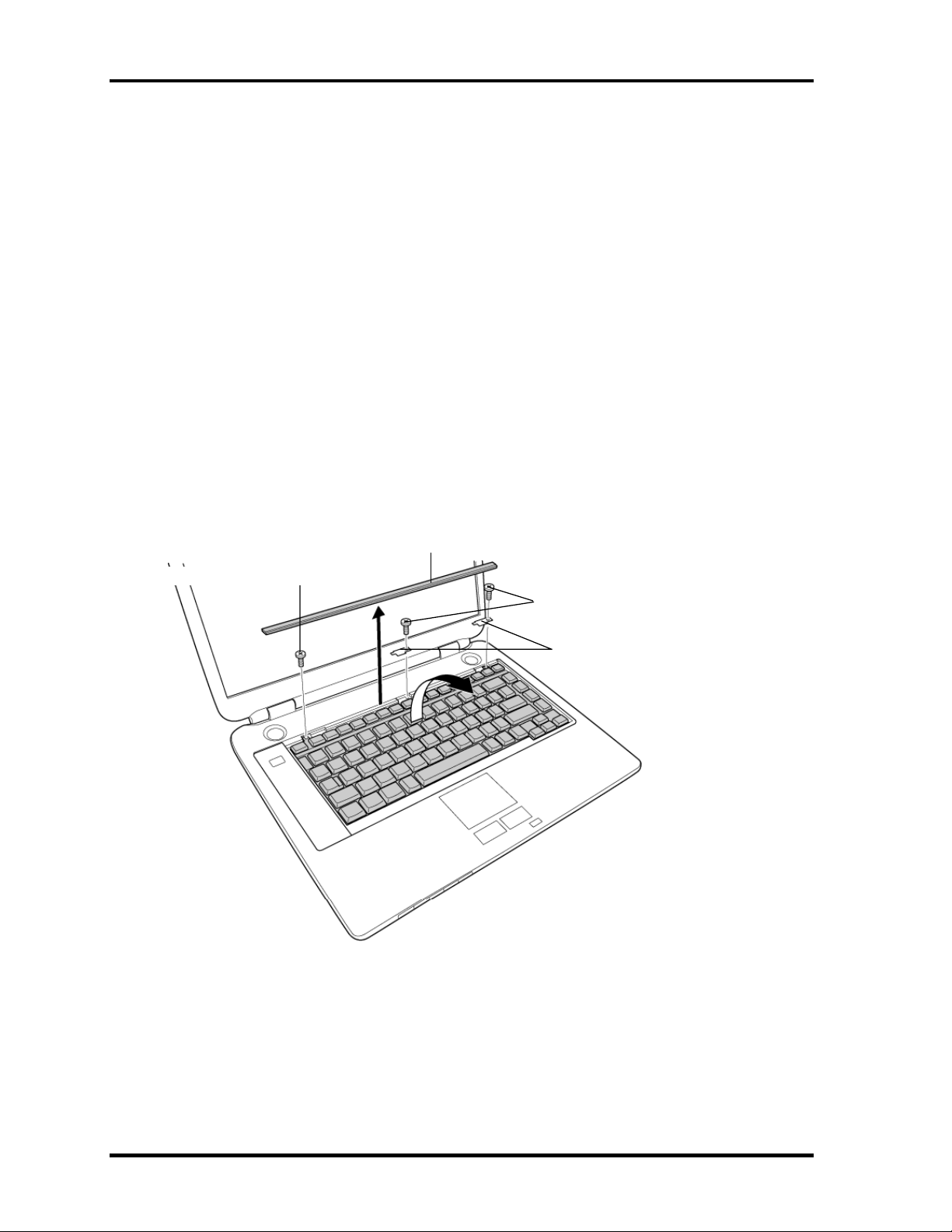
1. Turn the computer face up and open the display panel.
2. Insert your finger into the latches between the keyboard brace and the computer, and
lift up the keyboard brace to unlatch and remove it.
3. Remove the following screw securing the keyboard and keyboard hold plates. Then
remove the keyboard hold plate.
• M2×4B BIND screw ×1
Or
• M2×4 LH STICK screw ×1
M2×4B BIND or M2×4 LH STICK
Figure 4-11 Removing the keyboard brace and keyboard hold plate
Keyboard brace
M2×4B BIND or M2×4 LH STICK
Keyboard hold plate
4-26 Satellite M30 Maintenance Manual (960-455)
Page 2

4.9 Keyboard 4 Replacement Procedures
4. Lift the upper side of the keyboard out and turn it’s face down on the palm rest.
5. Remove the following screw securing the keyboard support plate and remove the
keyboard support plate.
• M2.5×8B FLAT HEAD screw ×1
M2.5×8B FLAT HEAD
Keyboard support
plate
PJ3200
Keyboard cable
Figure 4-12 Removing the keyboard support plate
7. Disconnect the keyboard cable from the connector PJ3200 on the system board, and
remove the keyboard.
Satellite M30 Maintenance Manual (960-455) 4-27
Page 3

4 Replacement Procedures 4.9 Keyboard
Installing the Keyboard
To install the keyboard, follow the steps below and refer to figures 4-11 to 4-12.
1. Place the keyboard face down on the palm rest.
2. Connect the keyboard cable to the connector PJ3200 on the system board.
3. Place the keyboard support plate and secure it with the following screw.
• M2.5×8B FLAT HEAD screw ×1
4. Turn the keyboard face up and put it on the computer. Make sure that there is no gap
between the keyboard and the computer.
5. Place the keyboard hold plates on the keyboard. Then secure the keyboard hold
plates and the keyboard with the following screws.
• M2×4B BIND screw ×2
Or
• M2×4 LH STICK screw ×2
6. Install the keyboard brace by pressing it from the topside.
4-28 Satellite M30 Maintenance Manual (960-455)
Page 4

4.10 Switch cover ASSY/Switch membrane 4 Replacement Procedures
4.10 Switch cover ASSY/Switch membrane
Removing the Switch cover ASSY/Switch membrane
To remove the Switch cover ASSY/Switch membrane, follow the steps below and refer to
figure 4-13 and 4-14.
1. Remove the switch cover ASSY by lifting the left side up, while releasing the latches.
Switch cover ASSY
Figure 4-13 Removing the switch cover ASSY
Satellite M30 Maintenance Manual (960-455) 4-29
Page 5

4 Replacement Procedures 4.10 Switch cover ASSY/Switch membrane
2. Pull up the insulator.
3. Disconnect the switch membrane cable from the connector PJ7001 on the system
board.
4. Remove the following screws fixing the switch membrane.
• M2.5×4B FLAT HEAD screw ×2
5. Remove the switch membrane by lifting up the left side of the switch membrane.
M2.5×4B FLAT HEAD
PJ7001
Switch membrane
Figure 4-14 Removing the switch membrane
Insulator
4-30 Satellite M30 Maintenance Manual (960-455)
Page 6

4.10 Switch cover ASSY/Switch membrane 4 Replacement Procedures
Installing the Switch cover ASSY/Switch membrane
To install the Switch cover ASSY/Switch membrane, follow the steps below and refer to
figure 4-13 and 4-14.
1. Place the switch membrane with the right side under the guides and secure it with
the following screws.
• M2.5×4B FLAT HEAD screw ×2
2. Connect the switch membrane cable to the connector PJ7001 on the system board.
3. Stick the insulator to fix the switch membrane.
4. Install the switch cover ASSY and engage the right-side latches.
Satellite M30 Maintenance Manual (960-455) 4-31
Page 7
4 Replacement Procedures 4.11 Display Assembly
4.11 Display Assembly
Removing the Display Assembly
To remove the display assembly, follow the steps below and refer to figures
4-15 to 4-17.
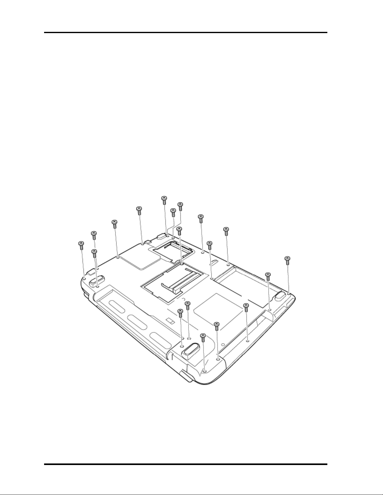
1. Turn the computer face down, and remove the following screws.
• M2.5×16B FLAT HEAD screw ×8 (“16” in the figure below)
• M2.5×10B FLAT HEAD screw ×8 (“10” in the figure below)
• M2×6B BIND screw ×2 (“6” in the figure below)
• M2×4B S-FLAT HEAD screw ×1 (“4” in the figure below)
16
16
16
10
10
10
6
6
16
10
16
10
10
16
10
10
4
16
16
Figure 4-15 Removing the display assembly (1)
4-32 Satellite M30 Maintenance Manual (960-455)
Page 8
4.11 Display Assembly 4 Replacement Procedures
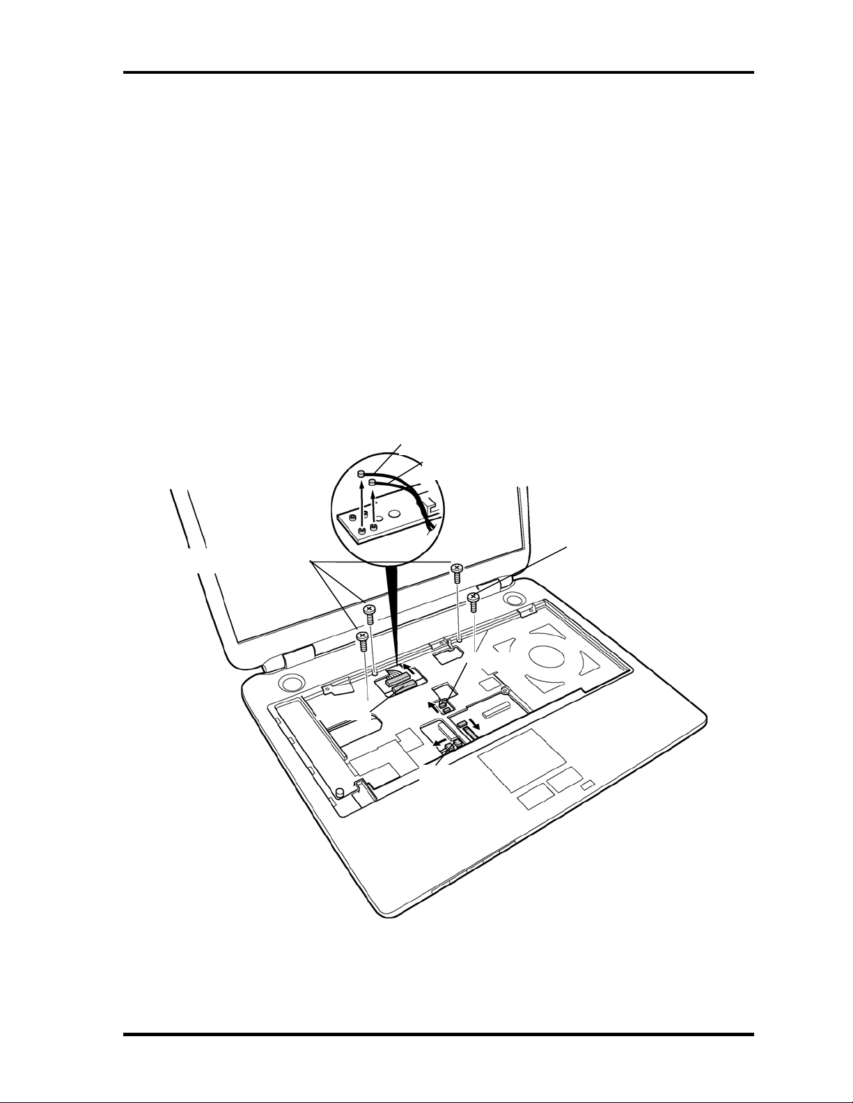
2. Turn the computer face up and open the display panel.
3. Remove the following screws securing the display assembly.
• M2.5×6B FLAT HEAD screw ×3
• M2.5×8B FLAT HEAD screw ×1
4. Disconnect the LCD cable from the connector PJ5600 on the system board.
5. Disconnect the two wireless LAN cables from the connectors, white and black on the
power board.
6. Disconnect the internal microphone cable from the connector PJ6001 on the system
board.
7. Disconnect the panel switch cable from the connector PJ7004 on the system board.
Wireless LAN cable (black)
M2.5×6B FLAT HEAD
Wireless LAN cable (white)
M2.5×8B FLAT HEAD
PJ7004
PJ5600
PJ6001
Figure 4-16 Removing the display assembly (2)
Satellite M30 Maintenance Manual (960-455) 4-33
Page 9

4 Replacement Procedures 4.11 Display Assembly
8. Remove the display assembly from the base assembly.
Display assembly
Figure 4-17 Removing the display assembly (3)
NOTE: When removing the display assembly, be careful not to damage any cables.
4-34 Satellite M30 Maintenance Manual (960-455)
Page 10

4.11 Display Assembly 4 Replacement Procedures
Installing the Display Assembly
To install the display assembly, follow the steps below and refer to figures 4-15 to 4-17.
1. Install the display assembly on the base assembly.
NOTE: When installing the display assembly, be careful not to pinch or damage any
cables.
2. Press along the edges of the display assembly to secure the latches.
3. Connect the panel switch cable to the connector PJ7004 on the system board.
4. Connect the internal microphone cable to the connector PJ6001 on the system
board.
5. Connect the LCD cable to the connector PJ5600 on the system board.
6. Connect the two wireless LAN cables to the connectors, white and black on the
power board.
7. Secure the display assembly with the following screws.
• M2.5×6B FLAT HEAD screw ×3
• M2.5×8B FLAT HEAD screw ×1
8. Turn the computer face down and secure the display assembly with the following
screws.
• M2.5×16B FLAT HEAD screw ×8
• M2.5×10B FLAT HEAD screw ×8
• M2×6B BIND screw ×2
• M2×4B S-FLAT HEAD screw ×1
Satellite M30 Maintenance Manual (960-455) 4-35
Page 11

4 Replacement Procedures 4.12 Touch Pad Button
T
4.12 Touch Pad Button
Removing the Touch Pad Button
To remove the touch pad button, follow the steps below and refer to figure 4-18.
1. Remove the following screws fixing the touch pad button.
• M2.5×4 Tapping screw ×3
2. Remove the touch pad button.
M2.5×4 Tapping
ouch pad button
Figure 4-18 Removing the touch pad button
Installing the Touch Pad Button
To installing the touch pad button, follow the steps below and refer to figure 4-18.
1. Install the touch pad button and fix it with the following screws.
• M2.5×4 Tapping screw ×3
4-36 Satellite M30 Maintenance Manual (960-455)
Page 12

4.13 Microphone 4 Replacement Procedures
4.13 Microphone
Removing the Microphone
To remove the Microphone, follow the steps below and refer to figures 4-19 and 20.
1. Remove the microphone from the guide.
Microphone
Figure 4-19 Removing the microphone
2. Peel the insulator on the back and remove the microphone cable from the guide.
3. Remove the microphone (with cable) through the hole to the front.
Insulator
Microphone cable
Figure 4-20 Removing the microphone cable
Satellite M30 Maintenance Manual (960-455) 4-37
Page 13

4 Replacement Procedures 4.13 Microphone
Installing the Microphone
To install the Microphone, follow the steps below and refer to figures 4-19 and 20.
1. Pass the microphone cable from the front to the back.
2. Set the microphone, putting the hole in the guide.
3. Pass the microphone cable through the slot with guides.
4-38 Satellite M30 Maintenance Manual (960-455)
Page 14

4.14 Touch Pad 4 Replacement Procedures
T
4.14 Touch Pad
Removing the Touch Pad
To remove the touch pad, follow the steps below and refer to figures 4-21.
1. Disconnect the touch pad flexible cable from the connector PJ3201 on the system
board.
2. Remove the following screws securing the touch pad.
• M2.5×8B FLAT HEAD screw ×1
• M2.5×4B FLAT HEAD screw ×1
3. Remove the touch pad.
M2.5×8B FLAT HEAD
ouch pad flexible cable
M2.5×4B FLAT HEAD
Figure 4-21 Removing the touch pad
4. Disconnect the touch pad flexible cable from the connector on the touch pad.
Satellite M30 Maintenance Manual (960-455) 4-39
Page 15

4 Replacement Procedures 4.14 Touch Pad
Installing the Touch Pad
To install the touch pad, follow the steps below and refer to figures 4-21.
1. Connect the touch pad flexible cable to the connector on the touch pad.
2. Install the touch pad and secure it with the following screws.
• M2.5×8B FLAT HEAD screw ×1
• M2.5×4B FLAT HEAD screw ×1
3. Connect the touch pad flexible cable to the connector PJ3201 on the system board.
4-40 Satellite M30 Maintenance Manual (960-455)
Page 16

4.15 RTC Battery 4 Replacement Procedures
4.15 RTC Battery
WARNING: When replacing the RTC battery, be sure to use genuine batteries or
replacement batteries authorized by Toshiba. Installing the wrong battery
could cause a battery explosion or other damage.
If the RTC battery is found abnormal, it must not be installed. Replace it
with a new battery, and dispose of the old one according to the local
regulations.
Check for any of the following signs of damage:
1) Electrolyte leakage
• Corrosion (greenish color) on the battery connector or cable
• Corrosion on the computer's battery connector
• White powder on any part of the battery
• White powder in the battery tray
• Clear liquid on the battery
• Clear liquid in the battery tray
• Clear liquid on any board near the battery
2) Damage to the connection cable
3) Damage to the connector housing
If any powder or liquid is found in or around the battery tray, clean it. Be
careful not to let any leaked material contact your eyes or mouth. Do not
inhale fumes from leaked material.
If leaked material contacts your skin, eyes or mouth, wash the affected area
thoroughly with clean water.
Satellite M30 Maintenance Manual (960-455) 4-41
Page 17

4 Replacement Procedures 4.15 RTC Battery
Removing the RTC Battery
To remove the RTC battery, follow the steps below and refer to figure 4-22.
1. Peel off the insulator.
2. Disconnect the RTC battery cable from the connector PJ8490 on the system board.
3. Remove the RTC battery.
Insulator
Insulator
RTC battery
RTC battery cable
Figure 4-22 Removing the RTC battery
Installing the RTC Battery
To install the RTC battery, follow the steps below and refer to figure 4-22.
1. Place the RTC battery into the slot.
2. Pass the RTC battery cable through the battery guide and connect the RTC battery
cable to the connector PJ8490 on the system board.
3. Fix the RTC battery with the insulator.
4-42 Satellite M30 Maintenance Manual (960-455)
Page 18

4.16 Sound Board/Touch Pad holder 4 Replacement Procedures
4.16 Sound Board/Touch Pad holder
4.16.1 Sound Board
Removing the Sound Board
To remove the sound board, follow the steps below and refer to figure 4-23.
1. Remove the following screw and the sound board.
• M2.5×6B FLAT HEAD screw ×1
2. Disconnect the sound board I/F cable from the connector on the sound board.
3. Peel the insulator.
M2.5×6B FLAT HEAD
Sound board
Sound board
Insulator
Figure 4-23 Removing the sound board
I/F cable
Satellite M30 Maintenance Manual (960-455) 4-43
Page 19

4 Replacement Procedures 4.16 Sound Board/Touch Pad holder
Installing the Sound Board
To install the sound board, follow the steps below and refer to figure 4-23.
1. Connect the sound board I/F cable to the connector on the sound board and secure it
with the insulator.
2. Install the sound board from the side with jacks and secure it with the following
screw.
• M2.5×6B FLAT HEAD screw ×1
4-44 Satellite M30 Maintenance Manual (960-455)
Page 20

4.16 Sound Board/Touch Pad holder 4 Replacement Procedures
T
r
4.16.2 Touch Pad holder
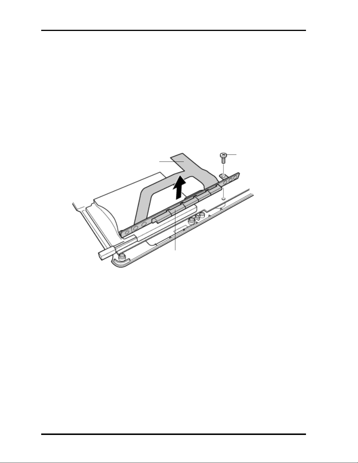
Removing the Touch Pad holder
To remove the touch pad holder, follow the steps below and refer to figures 4-24.
1. Disconnect the sound board I/F cable from the connector PJ7002 on the system
board.
2. Remove the touch pad holder from the system board.
Sound board
ouch pad holde
I/F cable
Figure 4-24 Removing the touch pad holder
Installing the Touch Pad holder
To install the touch pad holder, follow the steps below and refer to figures 4-24.
1. Install the touch pad holder on the system board.
2. Connect the sound board I/F cable to the connector PJ7002 on the system board.
Satellite M30 Maintenance Manual (960-455) 4-45
Page 21
4 Replacement Procedures 4.17 CD-Key assembly
M2×4B BIND
4.17 CD-Key assembly
Removing the CD-Key assembly
To remove the CD-key assembly, follow the steps below and refer to figures 4-25.
1. Disconnect the CD-key flexible cable from the connector PJ7000 on the system
board.
2. Remove the following screw and the CD-key assembly.
• M2×4B BIND screw ×1
CD-key flexible cable
CD-key
Figure 4-25 Removing the CD-key assembly
Installing the CD-Key assembly
To install the CD-key assembly, follow the steps below and refer to figures 4-25.
1. Place the CD-key assembly and secure it with the following screw.
• M2×4B BIND screw ×1
2. Connect the CD-key flexible cable to the connector PJ7000 on the system board.
4-46 Satellite M30 Maintenance Manual (960-455)
Page 22

4.18 System Board 4 Replacement Procedures
4.18 System Board
Removing the System Board
To remove the system board, follow the steps below and refer to figures 4-26 and 4-27.
1. Peel off the glass tape and disconnect the RGB cable from the connector PJ5621 on
the system board.
2. Disconnect the speaker cables from the connectors PJ6003 (red) and PJ6004 (blue)
on the system board.
3. Disconnect the USB cable from the connector PJ7003 on the system board.
4. Peel off the glass tapes and disconnect the battery cable from the connector PJ8810
and the network cable from the connector PJ4100on the system board.
5. Disconnect the fan cable from the connector PJ8770 on the system board and the
power cable from the connector CN3 on the power board.
6. Peel off the glass tape and disconnect the USB cable from the connector PJ7005 on
the system board.(VRAM64 only)
Glass tape
Network cable
USB cable
Speaker cable (red)
Speaker cable (blue)
Battery cable
Power cable
Fan cable
Glass tape
USB cable
Glass tape
Glass tape
RGB cable
*Case of the VRAM64 only
Figure 4-26 Removing the system board (1)
Satellite M30 Maintenance Manual (960-455) 4-47
Page 23

4 Replacement Procedures 4.18 System Board
7. Remove the following screws securing the system board.
• M2.5×6B FLAT HEAD screw ×1
8. Lift up the right side of the system board and remove it.
M2.5×6B FLAT HEAD
System board
Figure 4-27 Removing the system board (2)
4-48 Satellite M30 Maintenance Manual (960-455)
Page 24

4.18 System Board 4 Replacement Procedures
Installing the System Board
To install the system board, follow the steps below and refer to figures 4-26 and 27.
1. Install the system board from the left side.
NOTE: When installing the system board, be careful not to pinch or damage the USB
cable, RGB cable, battery cable speaker cable, network cable, fan cable or
power cable.
2. Secure the system board with the following screws.
• M2.5×6B FLAT HEAD screw ×1
3. Connect the USB cable to the connector PJ7005 on the system board and stick the
glass tape.(VRAM64 only)
4. Connect the fan cable to the connector PJ8770 on the system board.
5. Connect the RGB cable to the connector PJ5621 on the system board and stick the
glass tape.
6. Connect the battery cable to the connector PJ8810 on the system board.
7. Connect the power cable to the connector CN3 on the power board.
8. Connect the USB cable to the connector PJ7003 on the system board.
9. Connect the speaker cables to the connectors PJ6003 and PJ6004 on the system
board.
10. Connect the network cable to the connector PJ4100 on the system board and stick
the glass tapes.
Satellite M30 Maintenance Manual (960-455) 4-49
 Loading...