

Page 1

4.1 General 4 Replacement Procedures
4 Replacement Procedures
4.1 General
This section explains how to disassemble the computer and replace Field Replaceable Units
(FRUs). It may not be necessary to remove all the FRUs in order to replace one. The chart
below is a guide to which FRUs need to be removed in order to remove others. Always start
by removing the battery pack, next, optional items such as the optional PC card and optional
SD card, then follow the line on the chart to determine which FRU you must remove next in
order to repair the one you think is causing the computer to operate improperly. Refer to the
example at the bottom of the page.
How to See the Chart
Two examples of
referring to the chart are
shown below.
•
Removing the Display
assembly
4.2 Battery to 4.10 Switch
cover ASSY/Switch
membrane must be
removed.
Satellite M30 Maintenance Manual (960-455) 4-1
Page 2

4 Replacement Procedures 4.1 General
Safety Precautions
Before you begin disassembly, read the following safety precautions and observe them
carefully as you work.
DANGER: 1) Always use the genuine battery that is authorized by Toshiba or
compatible with the unit. Since other battery packs have different
specifications, they may be incompatible with the unit, and may burst or
explode.
Never heat or disassemble the battery pack, as that could cause leakage
of alkaline solution. Never throw the battery pack into a fire, as that
could cause the battery pack to explode.
2) The power supply, FL inverter and other components carry high
voltages. If you need to turn on the power of a partially disassembled
computer to check its operation, be very careful not to touch connectors
or components, in order to avoid the risk of electric shock.
Also, do not disassemble individual components in first-level
maintenance.
WARNING: 1) Turn off the power and disconnect the AC adaptor from the power
source, to avoid exposure to electric shock.
2) Batteries in the computer retain an electrical charge, so there is danger
of electrical shock even when the computer is disconnected from an AC
power source. Remove any metal jewelry or accessories such as
necklaces, bracelets or rings, in order to reduce the risk of electric
shock. Never work with wet or damp hands.
3) Be careful of edges and corners as these may cut.
CAUTION: 1) When you change a component, be sure the replacement component
meets the required specifications. Never use foreign parts, to avoid any
risk of damage to the computer.
2) To avoid any risk of short-circuit, fire or other internal damage, never
allow any metal objects such as screws or paper clips to fall into the
unit. Be sure to replace screws with the same size as those removed.
Make sure all screws are securely fastened. Loose screws can cause
short circuits, resulting in heat, smoke or fire.
3) Before lifting out an FRU or other component, make sure all cables to
the component have been disconnected, in order to reduce the risk of
accidental electric shock.
4) If you use AC power, be sure to use the cable that came with the
computer or one recommended by Toshiba.
5) Make sure that all replacement components meet the specifications for
the computer and that all cables and connectors are securely fastened, in
order to avoid the risk of electric shock.
6) Some parts inside the computer, such as the CPU and cooling module,
become very hot during operation. Conduct repair work after they have
cooled. Be careful around the CPU and cooling module to avoid burns.
4-2 Satellite M30 Maintenance Manual (960-455)
Page 3

4.1 General 4 Replacement Procedures
Before You Begin
Look over the procedures in this section before you begin disassembling the computer.
Familiarize yourself with the disassembly and reassembly steps. Begin each procedure by
removing the AC adapter and the battery pack as instructed in this section:
1. Do not disassemble the computer unless it is operating abnormally.
2. Use only the correct and approved tools.
3. Make sure the working environment is free from the following elements whether you
are using or storing the computer.
• Dust and contaminates
• Static electricity
• Extreme heat, cold and humidity
4. Make sure the FRU you are replacing is causing the abnormal operation by
performing the necessary diagnostics tests described in this manual.
5. Do not perform any operations that are not necessary and use only the described
procedures for disassembling and installing FRUs in the computer.
6. After removing parts from the computer, place them in a safe place away from the
computer so they will not be damaged and will not interfere with your work.
7. You will remove and replace many screws when you disassemble the computer.
When you remove screws, make sure they are placed in a safe place and identified
with the correct parts.
8. When assembling the computer make sure you use the correct screws to secure the
various pieces in place. Screw sizes are listed in their corresponding figures.
9. The computer contains many sharp edges and corners, so be careful not to injure
yourself.
10. After you have replaced an FRU, make sure the computer is functioning properly by
performing the appropriate test on the FRU you have fixed or replaced.
Satellite M30 Maintenance Manual (960-455) 4-3
Page 4

4 Replacement Procedures 4.1 General
Disassembly Procedures
The computer has two basic types of cable connectors:
• Pressure Plate Connectors
• Coaxial Cable Connectors
• Normal Pin Connectors
To disconnect a Pressure Plate connector, lift up the tabs on either side of the connector’s
plastic pressure plate and slide the cable out of the connector. To connect the cable to a
Pressure Plate connector, make sure the pressure plate is fully lifted and slide the cable into
the connector. Secure the cable in place by pushing the sides of the pressure plate down so
the plate is flush with the sides of the connector. Gently pull on the cable to make sure the
cable is secure. If you pull out the connector, connect it again making sure the connector’s
pressure plate is fully lifted when you insert the cable.
Coaxial cables should be disconnected with an antenna coaxial disconnector.
Standard pin connectors are used with all other cables. These connectors can be connected
and disconnected by simply pulling them apart or pushing them together.
Assembly Procedures
After you have disassembled the computer and fixed or repaired the problem that was
causing the computer to operate abnormally, you will need to reassemble the computer.
Install all the removed FRUs following the steps described in the corresponding sections in
this chapter.
While assembling the computer, remember the following general points:
• Take your time, making sure you follow the instructions closely. Most problems
arise when you get in a hurry assembling the computer.
• Make sure all cables and connectors are securely fastened.
• Before securing the FRU or other parts, make sure that screws or the FRU will
pinch no cables.
• Check that all latches are closed securely in place.
• Make sure all the correct screws are used to secure all FRUs. Using the wrong
screw can either damage the threads on the screw or the head of the screw and
may prevent proper seating of an FRU.
After installing an FRU in the computer, confirm that the FRU and the computer are
functioning properly.
4-4 Satellite M30 Maintenance Manual (960-455)
Page 5

4.1 General 4 Replacement Procedures
Tools and Equipment
The use of Electrostatic Discharge (ESD) equipment is very important for your safety and the
safety of those around you. Proper use of these devices will increase the success rate of your
repairs and lower the cost for damaged or destroyed parts. The following equipment is
necessary to disassemble and reassemble the computer:
• One M2 point size 0 Phillips screwdriver to remove and replace screws.
• One M2.5/M3 point size 1 Phillips screwdriver to remove and replace screws.
• One 4 mm flat-blade screwdriver.
• Tweezers, to lift out screws that you cannot grasp with your fingers.
• ESD mats for the floor and the table you are working on.
• An ESD wrist strap or heel grounder.
• Anti-static carpeting or flooring.
• Air ionizers in highly static sensitive areas.
• Antenna coaxial cable disconnector
Satellite M30 Maintenance Manual (960-455) 4-5
Page 6

4 Replacement Procedures 4.1 General
Screw Tightening Torque
When you fasten screws, be sure to follow the torque list below.
CAUTION: Overtightening can damage components and screws; undertightening can
result in electrical shorts or other damage if screws or components come
loose.
NOTE: Toshiba recommends that you use an electric screwdriver for quick and easy
operations.
• M2 0.17 N·m (1.7 kgf·cm)
• M2.5 0.30 N·m (3.0 kgf·cm)
• M3 0.57 N·m (5.6 kgf·cm)
NOTE: The computer contains several flat head screws. These screws have less contact
area with the screwdriver, so be careful to press firmly enough to prevent the
screwdriver from slipping out and damaging the screw head.
4-6 Satellite M30 Maintenance Manual (960-455)
Page 7

4.1 General 4 Replacement Procedures
Color of Screw Shaft
To avoid mistakes on the screw length, screw shafts are colored as follows:
Even number length screw: brown
Odd number length screw: white
Special length screw: blue
Screws whose lengths are indicated to one or more decimal places such as 2.5 mm or
2.8 mm.
Marking of Screws on the Computer Body
To make maintenance of the computer easier, markings of the kinds of the screws including
the types and lengths of the screws are indicated on the computer body.
Kind of screws Symbol
BIND screw B
FLAT HEAD screw F
SUPER FLAT HEAD screw S
TAPPING screw T
Other screws U
(Unique screws, STUD, etc.)
Examples:
6 mm BIND screw B6
12 mm BIND screw B12
5 mm FLAT HEAD screw F5
(Indicates the screwed length in round number regardless the length of the stud.)
Satellite M30 Maintenance Manual (960-455) 4-7
Page 8
4 Replacement Procedures 4.2 Battery Pack
4.2 Battery Pack
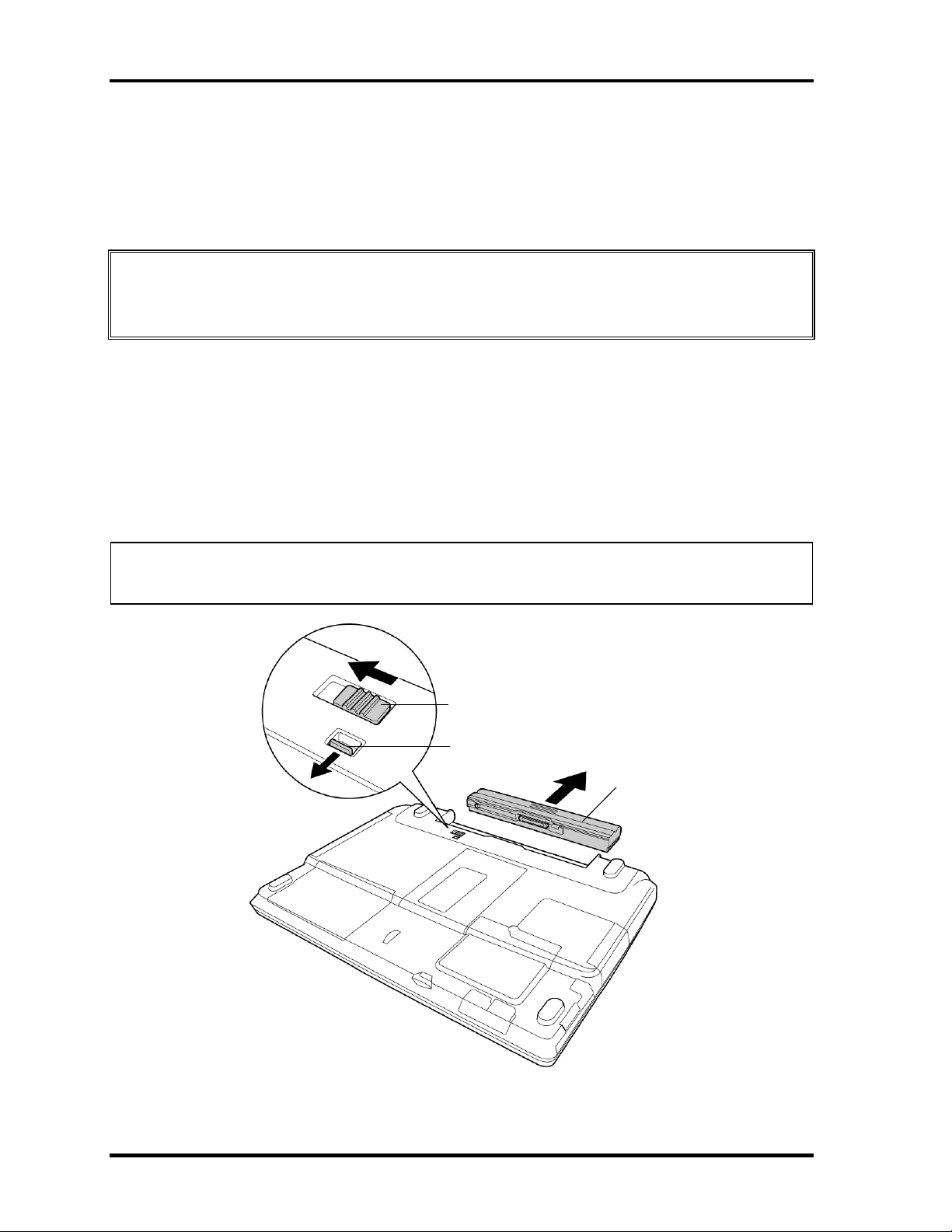
Removing the Battery Pack
To remove the battery pack, follow the steps below and refer to figure 4-1.
CAUTION: When handling battery packs, be careful not to short circuit the terminals.
Also do not drop, hit or apply impact; do not scratch, break, twist or bend
the battery pack.
1. Turn off the computer.
2. Disconnect the AC cable and other external devices from the computer.
3. Turn the computer face down.
4. Release the battery lock while sliding the battery latch, pull out the battery pack to
the arrow direction in the figure below.
NOTE: For environmental reasons, do not throw away a spent battery pack. Collect the
spent battery packs.
Battery latch
Battery lock
Battery
Figure 4-1 Removing the Battery pack
4-8 Satellite M30 Maintenance Manual (960-455)
Page 9

4.2 Battery Pack 4 Replacement Procedures
Installing the Battery Pack
To install the battery pack, follow the steps below and refer to figure 4-1.
CAUTION: The battery pack is a lithium ion battery, which can explode if not properly
replaced, used, handled or disposed of. For environmental reasons, collect
the spent battery packs. Use only batteries recommended by Toshiba as
replacements.
NOTE: Check the battery's terminals visually. If they are dirty, wipe them clean with a
dry cloth.
1. Push the battery pack into the battery slot. Make sure the battery pack is installed
securely.
2. Slide the battery lock into the lock position.
Satellite M30 Maintenance Manual (960-455) 4-9
Page 10

4 Replacement Procedures 4.3 PC Card
4.3 PC Card
Removing the PC Card
To remove the PC card, follow the steps below and refer to figure 4-2.
CAUTION: Before you remove a PC card, refer to the card's documentation and your
operating system documentation for proper procedures and precautions.
1. Turn the computer face up.
2. Push the eject button. It will pop out when you release it. Then press once more the
eject button to eject the PC card.
3. Grasp the PC card and pull it out.
PC card
Eject button
Figure 4-2 Removing the PC card
4-10 Satellite M30 Maintenance Manual (960-455)
Page 11

4.3 PC Card 4 Replacement Procedures
Installing the PC Card
To install the PC card, follow the steps below and refer to figure 4-2.
1. Make sure the eject button does not stick out.
2. Insert the PC card and press it until it is securely connected.
Satellite M30 Maintenance Manual (960-455) 4-11
Page 12

4 Replacement Procedures 4.4 SD Card
4.4 SD Card
Removing the SD Card
To remove the SD card, follow the steps below and refer to figure 4-3.
CAUTION: Before you remove the SD card, refer to the card's documentation and to
your operating system documentation for proper procedures and
precautions.
1. Turn the computer face up.
2. Push the SD card. It will pop out partly when you release, so pull out the card.
SD card
Figure 4-3 Removing the SD card
Installing the SD Card
To install the SD card, follow the steps below and refer to figure 4-3.
1. Insert the SD card and press it until it is securely connected.
4-12 Satellite M30 Maintenance Manual (960-455)
Page 13

4.5 HDD 4 Replacement Procedures
4.5 HDD
CAUTION: When handling the HDD, do not press the top surface as shown by the arrow.
Hold it by the sides.
HDD
Removing the HDD
To remove the HDD, follow the steps below and refer to figures 4-4 and 4-5.
1. Turn the computer upside down.
2. Remove the following screw securing the HDD cover. Remove the HDD cover by
lifting up.
• M2.5×10B FLAT HEAD screw ×1
M2.5×10B FLAT HEAD
HDD cover
HDD pack
Figure 4-4 Removing the HDD cover
Satellite M30 Maintenance Manual (960-455) 4-13
Page 14

4 Replacement Procedures 4.5 HDD
3. Push the tab of the HDD pack to the direction of the arrow and remove the HDD
pack. Be careful not to damage the connector.
NOTE: The following steps describe how to disassemble the HDD pack; however, do not
disassemble if the HDD is working properly.
4. Remove the following screws.
• M3×4S FLAT HEAD screw ×4
5. Remove the HDD bracket.
CAUTION: Do not apply pressure to the top or bottom of the HDD.
6. Remove the HDD from the aluminum laminate.
M3×4S FLAT HEAD
Aluminum laminate
M3×4S FLAT HEAD
HDD bracket
HDD
Figure 4-5 Removing the HDD bracket and HDD
4-14 Satellite M30 Maintenance Manual (960-455)
Page 15

4.5 HDD 4 Replacement Procedures
Installing the HDD
To install the HDD, follow the steps below and refer to figures 4-4 and 4-5.
CAUTION: Do not hold the HDD by its top and bottom flat surfaces. It may damage the
HDD.
1. Install the HDD to the aluminum laminate.
2. Place the HDD in the bracket.
3. Secure the HDD to the HDD bracket with the following screws.
• M3×4S FLAT HEAD screw ×4
CAUTION: Do not apply pressure to the middle of the HDD pack. It may damage the
HDD pack. Hold the HDD pack by its corners.
4. Hold the HDD pack and place it in the slot. Slide the HDD pack to the connector of
the computer to connect. Press to ensure a firm connection.
5. Seat the HDD cover and secure it with the following screw.
• M2.5×10B FLAT HEAD screw ×1
Satellite M30 Maintenance Manual (960-455) 4-15
Page 16

4 Replacement Procedures 4.6 Optical Drive
4.6 Optical Drive
Removing the Optical Drive
To remove the optical drive, follow the steps below and refer to figures 4-6 and 4-7.
CAUTION: Do not apply excessive force to the top of an optical drive.
1. Remove the following screws securing the optical drive.
• M2.5×4B FLAT HEAD screw ×2
2. Slide the optical drive outward to disconnect it from the connector PJ1820 on the
system board.
M2.5×4B FLAT HEAD
Figure 4-6 Removing the optical drive
Optical drive
4-16 Satellite M30 Maintenance Manual (960-455)
Page 17

4.6 Optical Drive 4 Replacement Procedures
3. Remove the following screws securing the plastic frame.
• M2×3C S-FLAT HEAD screw ×4
• Stepping screw ×1
Optical Drive
M2×3CS-FLAT HEAD
Stepping screw
M2×3CS-FLAT HEAD
Plastic frame
Figure 4-7 Disassembling the optical drivel
Satellite M30 Maintenance Manual (960-455) 4-17
Page 18

4 Replacement Procedures 4.6 Optical Drive
Installing the Optical drive
To install the optical drive, follow the steps below and refer to figures 4-6 and 4-7.
1. Seat the plastic frame on the side of the optical drive, and secure it with the
following screws.
• M2×3C S-FLAT HEAD screw ×4
• Stepping screw ×1
2. Slide the optical drive into the slot to connect it to the connector PJ1820 on the
system board.
3. Secure the optical drive with the following screws.
• M2.5×4B FLAT HEAD screw ×2
4-18 Satellite M30 Maintenance Manual (960-455)
Page 19

4.7 Memory module/ Modem Daughter Card 4 Replacement Procedures
r
4.7 Memory module/ Modem Daughter Card
CAUTION: The power of the computer must be turned off when you remove the memory
module. Removing a memory module with the power on risks damaging the
module or the computer itself.
Do not touch the memory module terminals. Any dirt on the terminals may
cause memory access problems.
Never press hard or bend the memory module.
4.7.1 Memory module
Removing the memory module
To remove a memory module, confirm that the computer is in boot mode. Then perform the
following procedures (See Figure 4-8).
1. Turn the computer upside down.
2. Loosen the screw (e-ring) fixing the memory slot cover.
3. Remove the memory slot cover.
4. Open the left and right latches and remove the memory module.
Memory slot cove
Screw
Memory module
Latches
Figure 4-8 Removing the memory module
Satellite M30 Maintenance Manual (960-455) 4-19
Page 20

4 Replacement Procedures 4.7 Memory module/ Modem Daughter Card
Installing the memory module
To install the memory module, confirm that the computer is in boot mode. Then follow the
steps below and refer to figures 4-8.
1. Insert the memory module into the connector of the computer slantwise (terminal
side first) and press it to connect firmly.
CAUTION: The power must be turned off when you insert the memory module. Inserting
a memory module with the power on might damage the module or the
computer itself.
Never press hard or bend the memory module.
2. Install the memory slot cover and secure it with the screw (e-ring).
3. When the power of the computer is turned on, the computer checks automatically the
memory size. Confirm that the new memory is detected correctly.
4. If the memory is not detected, check that it is connected correctly.
4-20 Satellite M30 Maintenance Manual (960-455)
Page 21

4.7 Memory module/ Modem Daughter Card 4 Replacement Procedures
4.7.2 Modem Daughter Card
Removing the Modem Daughter Card
To remove the modem daughter card, follow the steps below and refer to figure 4-9.
1. Remove the following screws securing the modem daughter card.
• M2×4B BIND screw ×2
2. Lift up the modem daughter card to disconnect it from the connector PJ3000 on the
system board.
4. Disconnect the modem cable from CN1 on the modem daughter card.
M2×4B BIND
Modem cable
MDC
PJ3000
Figure 4-9 Removing the modem daughter card
Satellite M30 Maintenance Manual (960-455) 4-21
Page 22

4 Replacement Procedures 4.7 Memory module/ Modem Daughter Card
Installing the Modem Daughter Card
To install the modem daughter card, follow the steps below and refer to figures 4-9.
1. Connect the modem cable to CN1 on the modem daughter card.
2. Connect the modem daughter card to the connector PJ3000 on the system board.
CAUTION: Be careful not to damage the card or connector.
3. Secure the modem daughter card with the following screws.
• M2×4B BIND screw ×2
4. Place the memory slot cover and secure it with the screw (e-ring).
4-22 Satellite M30 Maintenance Manual (960-455)
Page 23

4.8 Wireless LAN board 4 Replacement Procedures
4.8 Wireless LAN board
CAUTION: The power must be turned off when you remove the wireless LAN board.
Removing the wireless LAN board with the power on risks damaging the
card or the computer itself.
Never press hard or bend the wireless LAN board.
Removing the wireless LAN board
To remove the wireless LAN board, follow the steps below and refer to figure 4-10.
1. Turn the computer upside down.
2. Loosen the screw fixing the wireless LAN board cover.
• M2×4B BIND screw ×1
Or
• M2×4 LH STICK screw ×1
3. Peel off the glass tape and disconnect the two wireless LAN antenna cables (black
and white) from the wireless LAN board.
4. Open the left and right latches holding the wireless LAN board and remove it.
Wireless LAN board cover
M2×4B BIND or M2×4 LH STICK
Antenna cable (black)
Glass tape
Wireless LAN board
Antenna cable (white)
Figure 4-10 Removing the wireless LAN board
Satellite M30 Maintenance Manual (960-455) 4-23
Page 24

4 Replacement Procedures 4.8 Wireless LAN board
Installing the wireless LAN board
To install the wireless LAN board, follow the steps below and refer to figure 4-10.
1. Insert the wireless LAN board terminals slantwise into the connector on the
computer and press the wireless LAN board until it is securely in place.
2. Connect the wireless LAN cables (black and white) to the terminals on the wireless
LAN board and fix them with the glass tape.
3. Place the wireless LAN board cover and secure it with the following screw.
• M2×4B BIND screw ×1
Or
• M2×4 LH STICK screw ×1
4-24 Satellite M30 Maintenance Manual (960-455)
 Loading...