

Page 1
FILE NO. 810-200220
SERVICE MANUAL
HDD/DVD VIDEO RECORDER
RD-X2U
Oct., 2002
S
Page 2
LASER BEAM CAUTION LABEL
When the power supply is being turned on, you may not remove this laser beam caution label. If it removes, radiation of a
laser may be received.
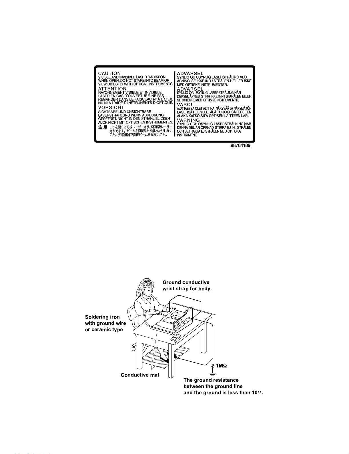
PREPARATION OF SERVICING
Pickup Head consists of a laser diode that is very susceptible to external static electricity.
Although it operates properly after replacement, if it was subject to electrostatic discharge during replacement,
its life might be shortened. When replacing, use a conductive mat, soldering iron with ground wire, etc. to
protect the laser diode from damage by static electricity.
And also, the LSI and IC are same as above.
Ground conductive
wrist strap for body.
Soldering iron
with ground wire
or ceramic type
1M
W
Conductive mat
The ground resistance
between the ground line
and the ground is less than 10W.
Page 3
SAFETY NOTICE
SAFETY PRECAUTIONS
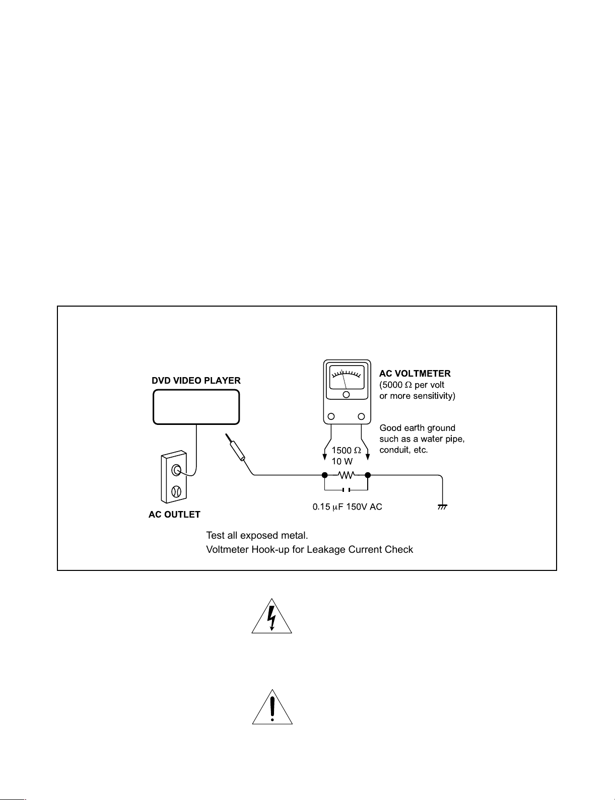
LEAKAGE CURRENT CHECK
Plug the AC line cord directly into a 120V AC outlet (do
not use an isolation transformer for this check). Use an
AC voltmeter, having 5000 W per volt or more sensitivity.
Connect a 1500 W 10 W resistor, paralleled by a 0.15 mF
150V AC capacitor between a known good earth ground
(water pipe, conduit, etc.) and all exposed metal parts of
cabinet (antennas, handle bracket, metal cabinet
screwheads, metal overlays, control shafts, etc.).
READING SHOULD NOT EXCEED 0.3V
Measure the AC voltage across the 1500 W resistor.
The test must be conducted with the AC switch on and
then repeated with the AC switch off. The AC voltage
indicated by the meter may not exceed 0.3 V. A reading
exceeding 0.3 V indicates that a dangerous potential
exists, the fault must be located and corrected.
Repeat the above test with the DVD VIDEO RECORDER
power plug reversed.
NEVER RETURN A DVD VIDEO PLAYER TO THE
CUSTOMER WITHOUT TAKING NECESSARY
CORRECTIVE ACTION.
DVD VIDEO PLAYER
AC OUTLET
Test all exposed metal.
Voltmeter Hook-up for Leakage Current Check
AC VOLTMETER
(5000Wper volt
or more sensitivity)
Good earth ground
such as a water pipe,
W
conduit, etc.
1500
10 W
0.15mF 150V AC
The lightning flash with arrowhead symbol, within an
equilateral triangle, is intended to alert the user to the
presence of uninsulated “dangerous voltage” within the
product’s enclosure that may be of sufficient magnitude to
constitute a risk of electric shock to persons.
The exclamation point within an equilateral triangle is
intended to alert the user to the presence of important
operating and maintenance (servicing) instructions in the
literature accompanying the appliance.
Page 4

1. OPERATING INSTRUCTIONS
Specifications
CONTENTS
SECTION 1
GENERAL DESCRIPTIONS
2. LOCATION OF MAIN PARTS AND
MECHANISM PARTS
2-1. Location of Main Parts
2-2. Standing PC Boards for Servicing
PART REPLACEMENT AND ADJUSTMENT PROCEDURES
1. REPLACEMENT OF MECHANICAL PARTS
1-1. Cabinet Replacement
1-1-1. Top Cover
1-1-2. HDD
1-1-3. Front Panel
1-1-4. Tray door
1-1-5. Operation panel door
1-1-6. RAM Drive
1-1-7. Fan
1-1-8. Rear Panel
1. CIRCUIT SYMBOLS AND
SUPPLEMENTARY EXPLANATION
1-1. Precautions for Part Replacement
1-2. Solid Resistor Indication
1-3. Capacitance Indication
1-4. Inductor Indication
1-5. Waveform and Voltage Measurement
1-6. Others
2. PRINTED WIRING BOARD AND
SCHEMATIC DIAGRAM
3. BLOCK DIAGRAMS
3-1. Overall Block Diagram
4. CIRCUIT DIAGRAMS
4-1. Power Supply Circuit Diagram
4-2. Front, Switch Circuit Diagram
SECTION 2
1-2. PC Board Replacement
1-2-1. Digital PC Board
1-2-2. Mother PC Board
1-2-3. Power PC Board
1-2-4. Battery PC Board
1-2-5. Front Display, Front Jack and Front Switch PC Board
SECTION 3
SERVICING DIAGRAMS
4-3. Front Jack Circuit Diagram
4-4. Front Display Circuit Diagram
4-5. Battery Circuit Diagram
4-6. Mother Circuit Diagram
4-6-1. Timer Circuit Diagram
4-6-2. Audio Circuit Diagram
4-6-3. Video / Tuner Circuit Diagram
4-7. Digital Circuit Diagram
5. PC BOARDS
5-1. Front Switch PC Board
5-2. Front Jack PC Board
5-3. Battery PC Board
5-4. Front Display PC Board
5-5. Mother PC Board
5-6. Digital PC Board
SAFETY PRECAUTION
NOTICE
ABBREVIATIONS
1. Integrated Circuit (IC)
2. Capacitor (Cap)
3. Resistor (Res)
SECTION 4
PARTS LIST
4. EXPLODED VIEWS
4-1. Packing Assembly
4-2. Chassis Assembly
5. PARTS LIST
Page 5

GENERAL DESCRIPTIONS
SECTION 1
GENERAL DESCRIPTIONS
1. OPERATING INSTRUCTIONS
Please refer to the owner's manual about the contents.
SECTION 1
Page 6
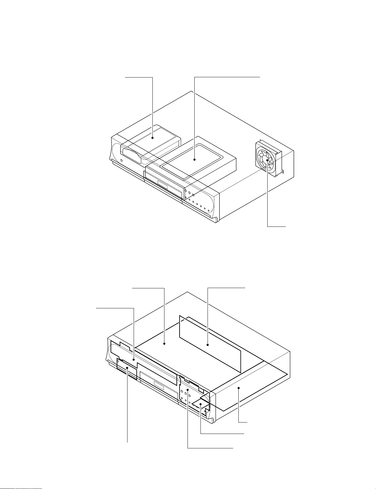
2. LOCATION OF MAIN PARTS AND MECHANISM PARTS
2-1. Location of Main Parts
HDD1 HDD UNIT RAM1 RAM DRIVE
2-2. Standing PC Boards for Servicing
EU05 Mother PC board EU01 Degital PC board
EU03 Front display
PC board
ZG45 FAN
Fig. 1-2-1
EU55 Front jack PC board
EU02 Power PC board
EU57 Battery PC board
EU04 Front switch PC board
Fig. 1-2-2
Page 7
SECTION 2
PART REPLACEMENT AND
ADJUSTMENT PROCEDURES
CAUTIONS BEFORE STARTING SERVICING
Electronic parts are susceptible to static electricity and may easily damaged, so do not forget to take a proper grounding
treatment as required.
Many screws are used inside the unit. To prevent missing, dropping, etc. of the screws, always use a magnetized screw-
driver in servicing. Several kinds of screws are used and some of them need special cautions. That is, take care of the
tapping screws securing molded parts and fine pitch screws used to secure metal parts. If they are used improperly, the
screw holes will be easily damaged and the parts can not be fixed.
ADJUSTMENT PROCEDURES
PART REPLACEMENT AND
1. REPLACEMENT OF MECHANICAL PARTS
1-1. Cabinet Replacement
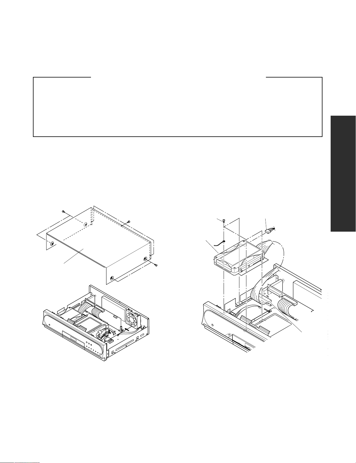
1-1-1. Top Cover
1. Remove seven screws (1), then remove the top cover
(2).
Screws (1)
Screws (1)
Top cover (2)
Screws (1)
1-1-2. HDD
1. Disconnect a connector (1).
2. Remove four screws (2) and a connector (3), then
remove the HDD (4).
Screws (2)
HDD (4)
SECTION 2
Connector (3)
Fig. 2-1-1
Connector (1)
Fig. 2-1-2
Page 8
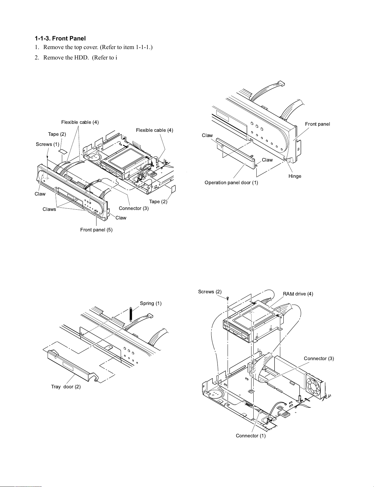
1-1-3. Front Panel
Front panel
Hinge
Claw
Claw
Operation panel door (1)
1. Remove the top cover. (Refer to item 1-1-1.)
2. Remove the HDD. (Refer to item 1-1-2.)
3. Remove five screws (1).
4. Peel off two tapes (2).
5. Disconnect a connector (3) and three flexible cables
(4).
6. Release five claws, then remove the front panel (5).
Flexible cable (4)
Tape (2)
Screws (1)
Flexible cable (4)
1-1-5. Operation panel door
1. Open the operation panel door (1).
2. Release two claws and unhinge the door (1). (Same
operation on the left and right doors.)
Claw
Tape (2)
Claws
Front panel (5)
Connector (3)
Claw
Fig. 2-1-3
1-1-4. Tray door
1. Remove a spring (1).
2. Remove the tray door (2) while slightly bending it
Spring (1)
Fig. 2-1-5
1-1-6. RAM Drive
1. Remove the HDD. (Refer to item 1-1-2.)
2. Remove the front panel. (Refer to item 1-1-3.)
3. Disconnect a connector (1).
4. Remove four screws (2), disconnect a connector (3),
then remove the RAM drive (4).
Screws (2)
RAM drive (4)
Connector (3)
Tray door (2)
Fig. 2-1-4
Connector (1)
Fig. 2-1-6
Page 9

1-1-7. Fan
1. Remove a connector (1) and two screws (2) and the
fan (3).
Fan (3)
1-2. PC Board Replacement
1-2-1. Digital PC Board
1. Lift two board stoppers up in the direction of the
arrow, remove the digital PC board (2) and disconnect
two connectors (3).
Digital PC board (2)
Connector (1)
Screws (2)
Fig. 2-1-7
1-1-8. Rear Panel
1. Disconnect a connector (1) and twelve screws (2),
then remove the rear panel (3).
Real panel (3)
Screws (2)
Connector (3)
PC board stopper (1)
Fig. 2-1-9
1-2-2. Mother PC Board
1. Remove the HDD. (Refer to item 1-1-2.)
2. Remove the front panel. (Refer to item 1-1-3.)
3. Remove the RAM drive. (Refer to item 1-1-6.)
4. Remove the rear panel. (Refer to item 1-1-8.)
5. Remove the digital PC board. (Refer to item 1-2-1.)
6. Lift the connector (1) up in the direction of the arrow.
7. Remove six screws (2), then remove the mother PC
board (3).
Connector (1)
Fig. 2-1-8
Screws (2)
Mother
PC board (3)
Connector (1)
Fig. 2-1-10
Page 10
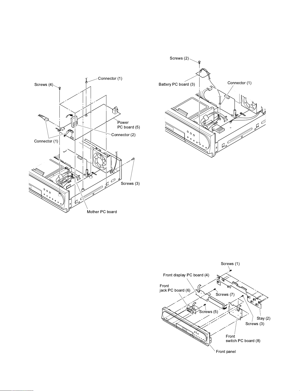
1-2-3. Power PC Board
Screws (2)
Battery PC board (3)
Connector (1)
1. Disconnect three connectors (1).
2. Lift a connector (2) up towards the mother board side,
and remove it.
3. Remove a screw (3), five screws (4) and the power PC
board (5).
Connector (1)
Screws (4)
Power
PC board (5)
Connector (2)
Connector (1)
1-2-4. Battery PC Board
1. Disconnect a connector (1) and remove a screw (2)
and the battery PC board (3).
Fig. 2-1-12
Mother PC board
Fig. 2-1-11
Screws (3)
1-2-5. Front Display, Front Jack and Front Switch
PC Board
1. Remove the front panel. (Refer to item 1-1-3.)
2. Remove nine screws (1), then remove the stay (2).
3. Remove four screws (3), then remove the front display
PC board (4).
4. Remove four screws (5), then remove the front jack
PC board (6).
5. Remove two screws (7), then remove the front switch
PC board (8).
Screws (1)
Front display PC board (4)
Front
jack PC board (6)
Screws (7)
Screws (5)
Stay (2)
Screws (3)
Front panel
Fig. 2-1-13
Front
switch PC board (8)
Page 11
100k
Rated Wattage Type Tolerance
100
m
Temperature
response
Rated
voltage
Tolerance
SECTION 3
SERVICING DIAGRAMS
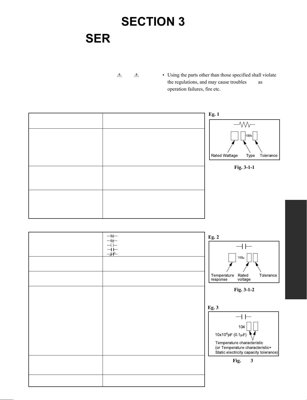
1. CIRCUIT SYMBOLS AND SUPPLEMENTARY EXPLANATION
1-1. Precautions for Part Replacement
• In the schematic diagram, parts marked (ex.
F801) are critical part to meet the safety regulations,
so always use the parts bearing specified part codes
(SN) when replacing them.
1-2. Solid Resistor Indication
Unit None ........... W
K ........... kW
M ........... MW
Tolerance None ........... ±5%
B ........... ±0.1%
C ........... ±0.25%
D ........... ±0.5%
F ........... ±1%
G ........... ±2%
K ........... ±10%
M ........... ±20%
Rated Wattage (1) Chip Parts
None .........1/16W
(2) Other Parts
None ......... 1/6W
Other than above, described in the Circuit Diagram.
Type None ........... Carbon film
S ........... Solid
R ........... Oxide metal film
M ........... Metal film
W ...........Cement
FR ........... Fusible
• Using the parts other than those specified shall violate
the regulations, and may cause troubles such as
operation failures, fire etc.
Eg. 1
Fig. 3-1-1
SERVICING DIAGRAMS
1-3. Capacitance Indication
Symbol
Unit None ........... F
Rated voltage None ........... 50V
Tolerance (1) Ceramic, plastic, and film capacitors of which
Temperature characteristic None ........... SL
(Ceramic capacitor) For others, temperature characteristics are
Static electricity capacity Sometimes described with abbreviated letters as
(Ceramic capacitor) shown in Eg. 3.
+
........... Electrolytic, Special electrolytic
NP
........... Non polarity electrolytic
........... Ceramic, plastic
M
........... Film
........... Trimmer
m ........... mF
p ........... pF
For other than 50V and electrolytic capacitors,
described in the Circuit Diagram.
capacitance are more than 10 pF.
None ........... ±5% or more
B ........... ±0.1%
C ........... ±0.25%
D ........... ±0.5%
F ........... ±1%
G ........... ±2%
(2) Ceramic, plastic, and film capacitors of which
capacitance are 10 pF or less.
None ........... more than ±5 pF
B ........... ±0.1 pF
C ........... ±0.25 pF
(3) Electrolytic, Trimmer
Tolerance is not described.
described. (For capacitors of 0.01 mF and
no indications are described as F.)
Eg. 2
Fig. 3-1-2
Eg. 3
104
4
10x10
pF (0.1mF)
Temperature characteristic
(or Temperature characteristic+
Static electricity capacity tolerance)
Fig. 3-1-3
SECTION 3
Page 12

1-4. Inductor Indication
Type name
10
m
Type Tolerance
Unit None ........... H
m ........... mH
m ...........mH
Tolerance None ........... ±5%
B ........... ±0.1%
C ........... ±0.25%
D ........... ±0.5%
F ........... ±1%
G ........... ±2%
K ........... ±10%
M ........... ±20%
1-5. Waveform and Voltage Measurement
• The waveforms for CD/DVD and RF shown in the
circuit diagrams are obtained when a test disc is
played back.
• All voltage values except the waveforms are expressed
in DC and measured by a digital voltmeter.
1-6. Others
• The parts indicated with "NC" or "KETU" etc. are not
used in the circuits of this model.
Eg. 4
Fig. 3-1-4
Eg. 5
Fig. 3-1-5
Page 13
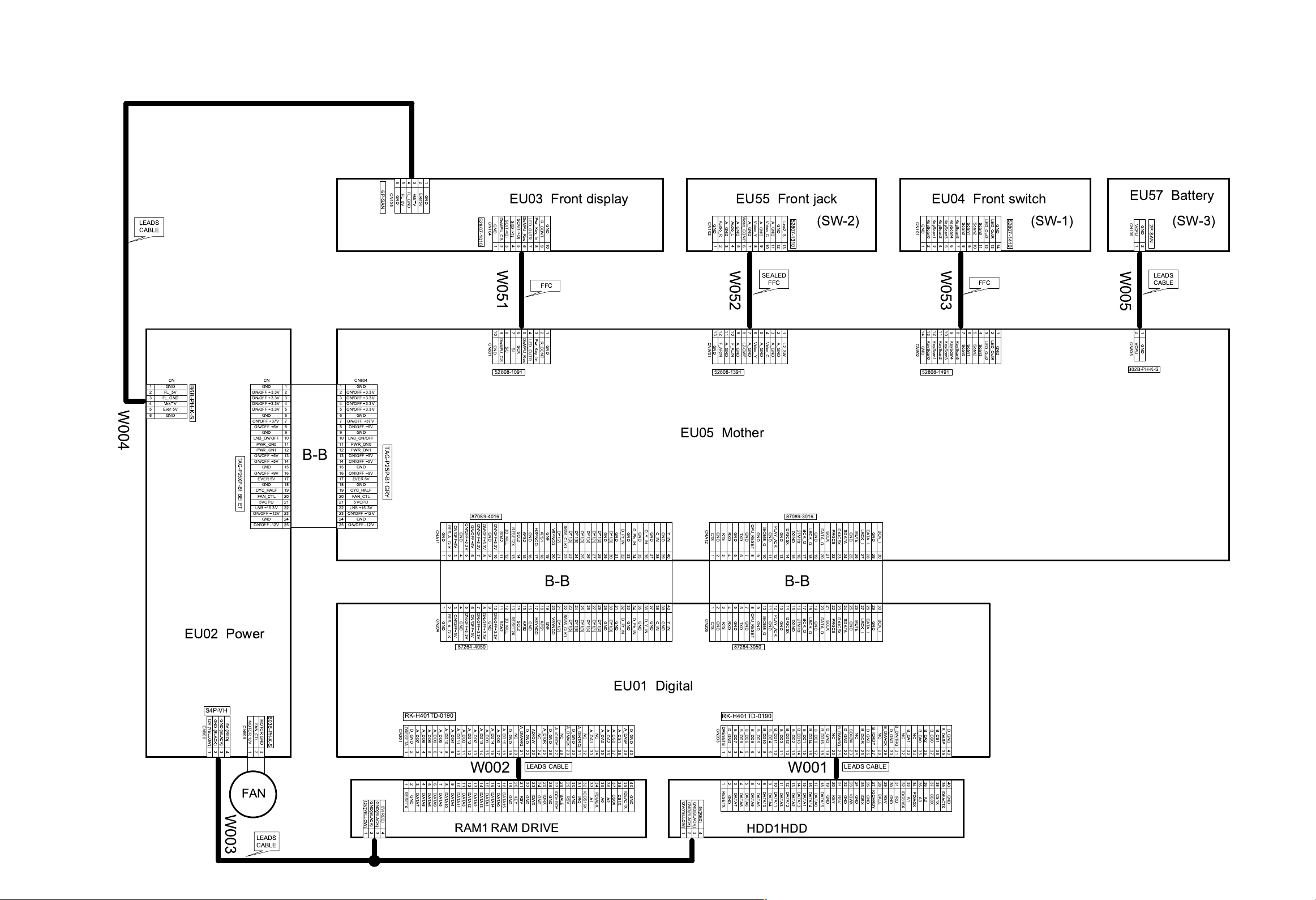
2. PRINTED WIRING BOARD AND SCHEMATIC DIAGRAM
65432
GND
FL_5V
FL_GND
Vkk**V
Ever5V
1
GND
52807-1010
LEADS
CABLE
6P-SAN
CN105
EU03 Front display EU55 Front jack
DisMPU_CS
SCK(T->D)
SO(T->D)
SI(D->T)
CN104
GND GND
123456789
DisMPU_Res
LED_OUTR
Pwr_Key_In
R_CONT
GND
10
CN102
Video_CONP
Audio_R
Audio_L
A_GND A_GND
A_GND A_GND
A_GND A_GND
GND GND
123456789
Video_C
Video_Y
Line2_S
A_GND
A_GND
GND
101112
13
EU04 Front switch
LED_OutR
KeyScan5
Scan0
Scan1
Scan2
Scan3
1011121314
LED_Out2
GND
52807-1410
KeyScan0
KeyScan1
KeyScan2
KeyScan3
52807-1310
(SW-2) (SW-1) (SW-3)
CN101
KeyScan4
GND
123456789
EU57 Battery
CN106
2P-SAN
VCPU
GND
1
2
1
2
3
4
W004
5
6
CN
B6B-PH-K-S
GND
FL_5V
FL_GND
Vkk**V
Ever 5V
GND
EU02 Power
TAG-P25XP-B1 BEI ET
CN
GND
ON/OFF +3.3V
ON/OFF +3.3V
ON/OFF +3.3V
ON/OFF +3.3V
GND
ON/OFF +37V
ON/OFF +6V
GND
LNB_ON/OFF
PWR_ON0
PWR_ON1
ON/OFF +5V
ON/OFF +5V
GND
ON/OFF +9V
EVER 5V
GND
CYC_HALF
FAN_CTL
5VCPU
LNB+15.3V
ON/OFF +12V
GND
ON/OFF -12V
W051
FFC
10
987654321
DisMPU_Res
DisMPU_CS
CN801
CN804
1
2
3
4
5
6
7
8
9
10
11
12
13
B-B
14
15
16
17
18
19
20
21
22
23
24
25
1
2
ON/OFF +3.3V
3
ON/OFF +3.3V
4
ON/OFF +3.3V
5
ON/OFF +3.3V
6
7
ON/OFF +37V
8
ON/OFF +6V
9
10
LNB_ON/OFF
11
12
13
ON/OFF +5V
14
ON/OFF +5V
15
16
ON/OFF +9V
17
18
19
CYC_HALF
20
21
22
LNB+15.3V
23
ON/OFF +12V
24
25
ON/OFF -12V
GND
GND
GND
PWR_ON0
PWR_ON1
GND
EVER 5V
GND
FAN_CTL
5VCPU
GND
TAG-P25P-B1 GRY
RES_A_CLK
ON/OFF+5V
CNA11
GND
GND
123456789
52808-1091
87089-4016
ON/OFF+3.3V
ON/OFF+3.3V
ON/OFF+3.3V
ON/OFF+3.3V
ON/OFF+5V
SDA2
GND
10111213141516171819202122232425262728293031323334353637383940
SO
SI
RESET2X
3D_KILL
SCK
SCL2
LED_OUTR
APS2
GND
Pwr_Key_In
R_CONT
HSYNCO
APS1
GND
GNF
VSYNCO
DY1[7]
R656_CLK1
DY1[5]
DY1[6]
DY1[3]
DY1[4]
DY1[1]
DY1[2]
GND
DY1[0]
GND
D_Pr_IN
GND
D_Pb_IN
GND
D_Y_IN
EU05 Mother
C_IN
Y_IN
GND
GND
B-B
123456789
RES_A_CLK
ON/OFF+5V
CN204
GND
GND
87264-4050
10111213141516171819202122232425262728293031323334353637383940
ON/OFF+3.3V
ON/OFF+3.3V
ON/OFF+3.3V
ON/OFF+3.3V
ON/OFF+5V
GND
SDA2
RESET2X
3D_KILL
SCL2
APS2
GND
HSYNCO
APS1
GNF
VSYNCO
DY1[7]
R656_CLK1
DY1[5]
DY1[6]
DY1[3]
DY1[4]
DY1[1]
DY1[2]
GND
DY1[0]
GND
D_Pr_IN
GND
D_Pb_IN
GND
D_Y_IN
GND
C_IN
GND
Y_IN
W052
131211
10
987654321
CNW01
F_ARIN
F_ALIN
52808-1391
CNA12
GND
GND
RXD
CTS
RTS
123456789
123456789
CN205
GND
GND
RXD
CTS
RTS
87264-3050
SEALED
FFC
Video_C
Video_Y
L2-CMP
TXD
A_GND
A_GND
A_GND
L2_SW
87089-3016
PLAY_ACK
IEC958_O
GND
GND
101112131415161718192021222324252627282930
GND
DA3CSX
DGND
27MHz
BCK_O
LRCK_O
DATA_O
SCLK
GND
GND
CPU_RESET
B-B
101112131415161718192021222324252627282930
CPU_RESET
PLAY_ACK
IEC958_O
GND
GND
GND
TXD
GND
DA3CSX
DGND
27MHz
BCK_O
LRCK_O
DATA_O
SCLK
GND
DA1CSX
PRGCS
DA1CSX
PRGCS
SDATA
SDATA
GND
GND
MUTE
MUTE
W053
FFC
131211
10
14
987654321
KeyScan0
KeyScan1
KeyScan2
KeyScan3
KeyScan4
CN802
GND
KeyScan5
52808-1491
LRCK_I
DATA_I
BCK_I
GND
LRCK_I
DATA_I
BCK_I
GND
Scan0
Scan1
Scan2
Scan3
LED_OutR
LED_Out2
GND
W005
2
1
CN805
VCPU
GND
B02B-PH-K-S
LEADS
CABLE
S4P-VH
12V (YELLOW)
CN806
123
GND (BLACK)
GND (BLACK)
5V (RED)
4
W003
MOTOR 12V
FAN_CTL
CN809
1
2
FAN
LEADS
CABLE
B03B-PH-K-S
MOTOR GND 3
12V(YELLOW)
GND(BLACK)
123
GND(BLACK)
5V(RED)
4
RK-H401TD-0190
DRESETA
D_GND
CN201
A_DD7
A_DD8
A_DD6
123456789
123456789
RESETX
DATA7
DATA8
DATA6
GND
A_DD10
A_DD11
A_DD12
A_DD9
A_DD5
A_DD13
A_DD4
A_DD3
A_DD2
A_DD1
10111213141516171819202122232425262728293031323334353637383940
W002 W001
10111213141516171819202122232425262728293031323334353637383940
DATA10
DATA11
DATA12
DATA4
DATA3
DATA2
DATA13
DATA1
DATA9
DATA5
A_DD14
A_DD0
DATA14
DATA0
A_DMARQ
A_DD15
D_GND
A_DIOR
D_GND
ADIOW
NC
NC
LEADS CABLE LEADS CABLE
DATA15
IOWX
GND
IORX
GND
GND
RSV
KEY
A_IORDY
D_GND
IOCHRDY
GND
NC
BALE
A_DMACK
D_GND
GND
RSV
A_DINTRQ
IRQ
RAM DRIVERAM1
EU01 Digital
A_DA1NCA_DA0
A_DA2
A_CS0
A1
PDIAGX
A0
A_CS1
CS0X
CS1X
A2
NC
IOCS16X
A_DASP
D_GND
IDEACTX
GND
12V(YELLOW)
GND(BLACK)
123
GND(BLACK)
5V(RED)
4
RK-H401TD-0190
DRESETB
D_GND
CN203
B_DD7
B_DD8
B_DD6
B_DD9
123456789
123456789
RESETX
DATA7
DATA8
DATA6
DATA9
GND
HDD1HDD
B_DD10
B_DD11
B_DD12
B_DD5
DATA5
DATA10
B_DD13
B_DD4
B_DD3
B_DD2
B_DD1
10111213141516171819202122232425262728293031323334353637383940
10111213141516171819202122232425262728293031323334353637383940
DATA11
DATA12
DATA13
DATA4
DATA3
DATA2
DATA1
B_DD14
B_DD0
DATA14
DATA0
B_DD15
D_GND
DATA15
GND
NC
KEY
B_DMARQ
D_GND
GND
RSV
BDIOW
IOWX
NC
GND
B_DIOR
IORX
D_GND
GND
B_IORDY
NC
IOCHRDY
BALE
B_DMACK
D_GND
GND
RSV
B_DINTRQ
B_DA1NCB_DA0
NC
IOCS16X
IRQ
A1
PDIAGX
A0
B_DASP
D_GND
B_DA2
B_CS0
B_CS1
IDEACTX
CS0X
CS1X
GND
A2
Fig. 3-2-1
Page 14
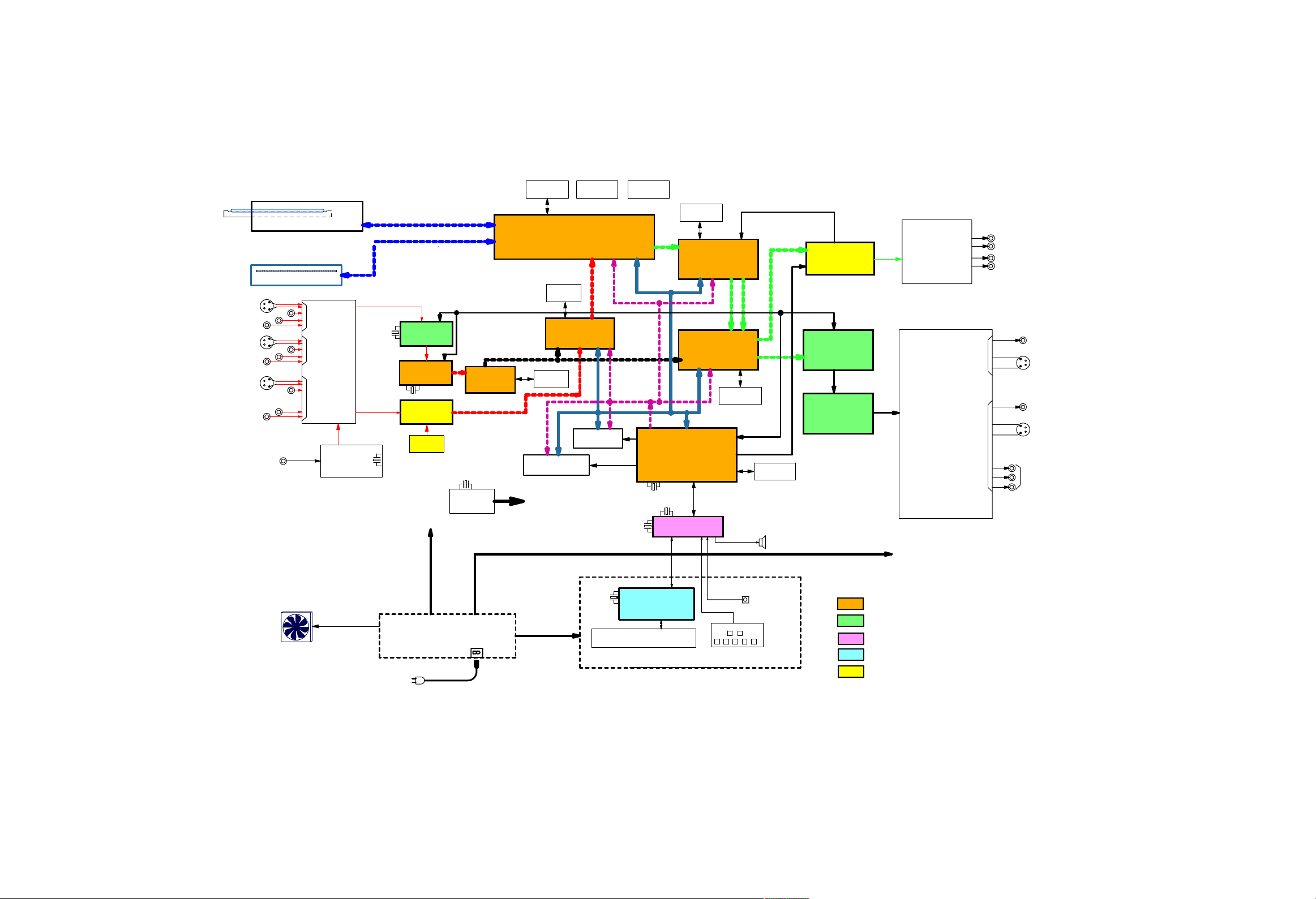
3. BLOCK DIAGRAMS
3-1. Overall Block Diagram
S-in
C_Video-in
Audio-in L/R
S-in
C_Video-in
Audio-in L/R
S-in
C_Video-in
Audio-in L/R
VHF/UHF
DVD RAM/R Drive
80GB Hard DisK Drive
IN_1
IN_2
INPUT
Line Selector
IN_3
V/U Tuner
ENG34509G
20MHz
ICa17
4.0MHz
ICX11
uPD64083
3DYC_DNR
IC200
Video
AD Converter
SAA7118
24.576MHz
Audio
AD Converter
CS5331
ICa16
PLL
PLL1700
IC212
Frame sync
TC200G08AF
12.288MHz
OSC
27MHz
-0031(Z)
8MB
SDRAM
CYGNUS
ATAPI control
TC223G66TB-7002(Z)
16MB
SDRAM
IC223
MPEG2 Encoder
uPD61052
2MB
SDRAM
8MB FLASH ROM
4kB
EEP_ROM
32MB SDRAM
15MHz
12.5MHz
4kB
EEP_ROM
IC247
32.785KHz
4MB
SDRAM
PS & DVD Decoder
ZR36735
IC209
Graphic Processor
TL750
Main MPU
HD6417612
Timer CPU
uPD784225Y
IC221
IC234
8MB
SDRAM
8kB
EEP_ROM
ICa02
Audio DAC
AD1985
Video Encoder
ADV7172
Video Driver
MM1567
ICW07
ICW05
Audio LPF
&Amplifier
ANALOG
CIRCUIT
Audio OUT
VIDEO
ANALOG
CIRCUIT
Video OUT
OUT_1
OUT_2
OUT_1
OUT_2
Lch
Rch
Lch
Rch
Y
Cb
Cr
PROGRESSIVE / COLOR
DIFFERENCE
Video OUT
D1 OUTPUT Terminal
COMPOSIT
Video OUT
S Video
OUT
COMPOSIT
Video OUT
S Video
OUT
DC FAN
POWER_UNIT
AC IN
AC 100V
5MHz
FL_CPU
uPD780204Y
FL_Tube
FRONT UNIT
KEY
R.S
: Digital
: Video/Tuner
: Timer
: Display
: Audio
Fig.3-3-1
Page 15
2 5 6 7 89
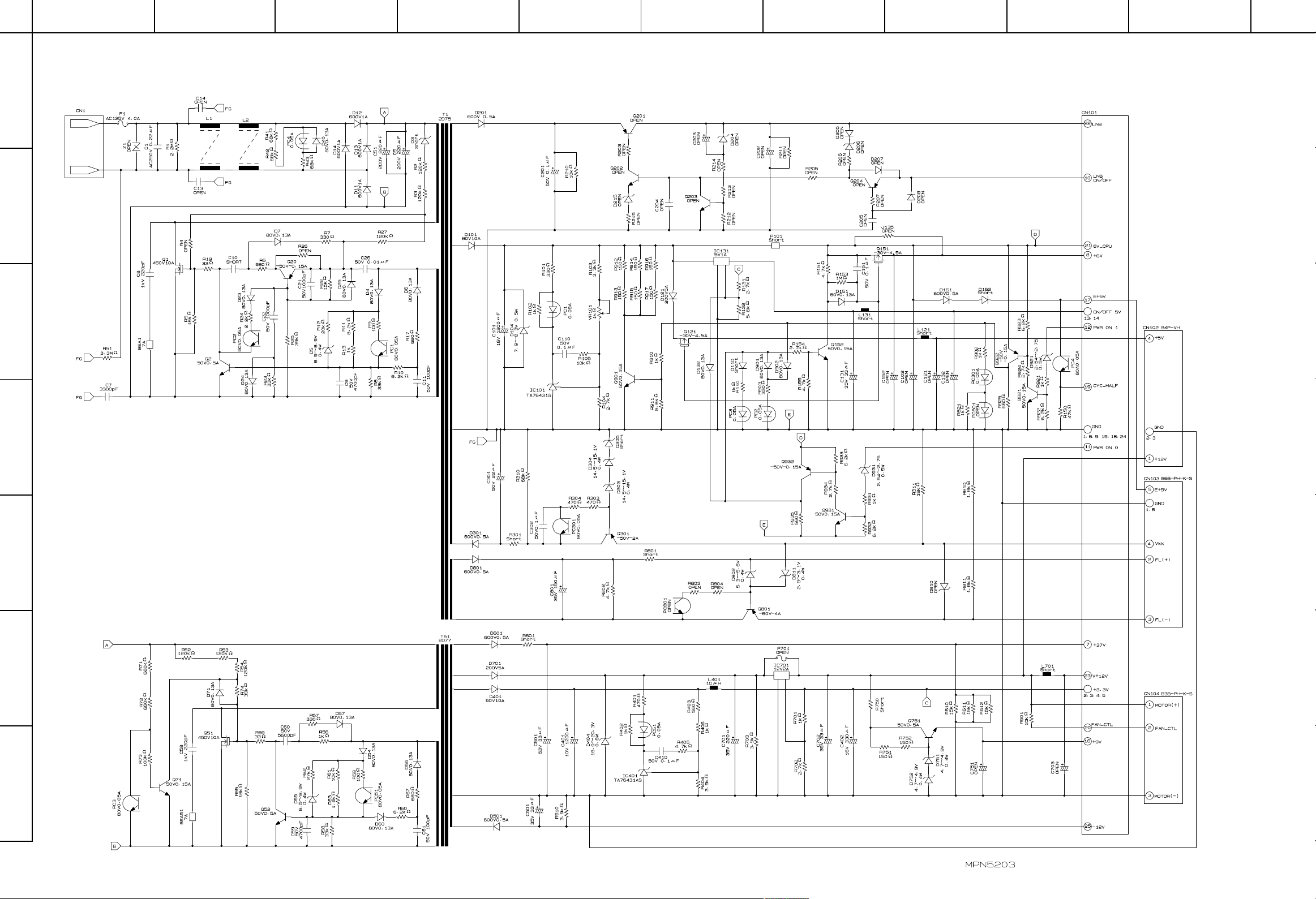
4. CIRCUIT DIAGRAMS
10134
A
B
C
4-1. Power Supply Circuit Diagram
D
E
F
G
Fig. 3-4-1
Page 16
A
B
C
2 5 6 7 89
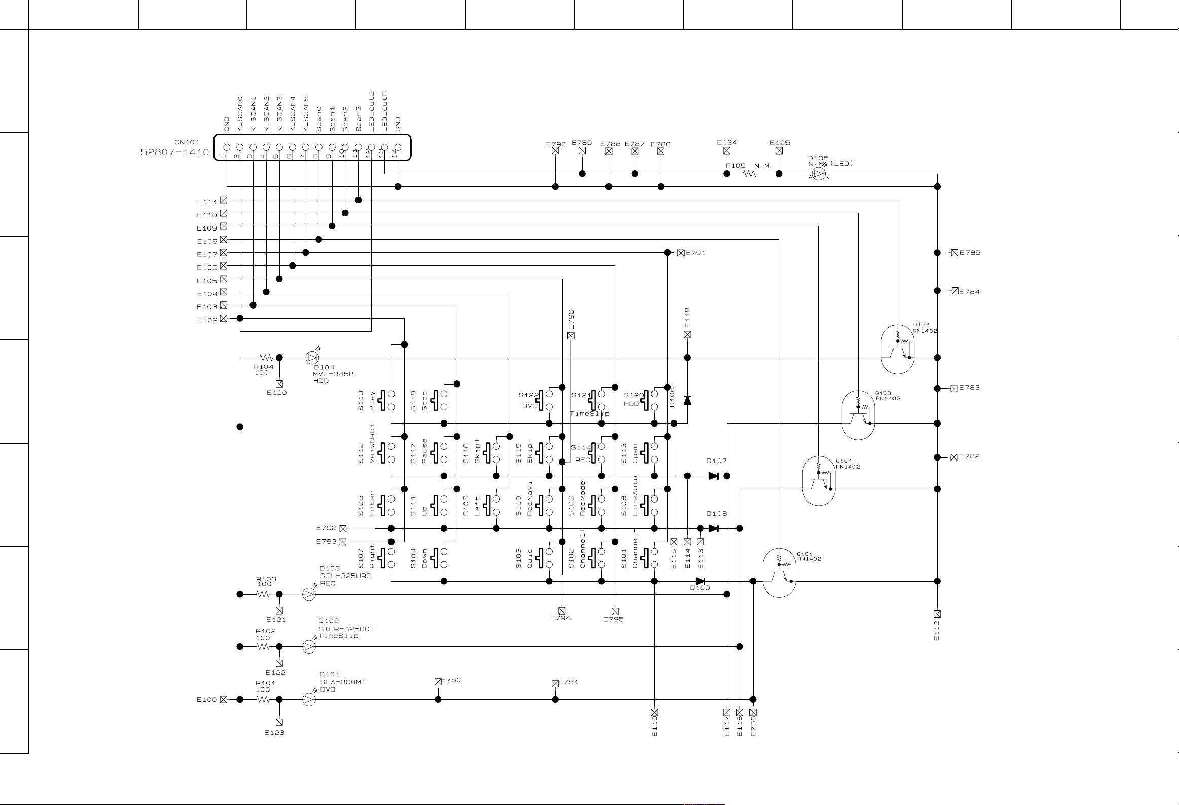
4-2. Front, Switch Circuit Diagram
10134
D
E
F
G
Fig. 3-4-2
Page 17
A
B
C
134
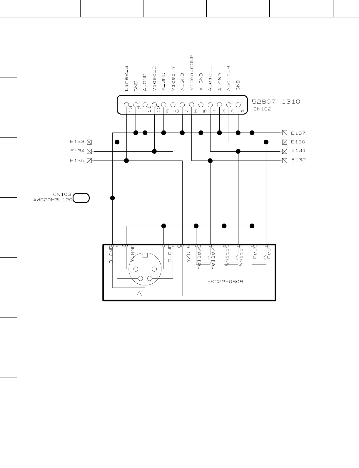
4-3. Front Jack Circuit Diagram
2 5
D
E
F
Fig. 3-4-3
G
Page 18

A
B
C
2 5 6 7 89
4-4. Front Display Circuit Diagram
10134
D
E
F
G
Fig. 3-4-4
Page 19

A
B
C
134
4-5. Battery Circuit Diagram
2 5
D
E
F
Fig. 3-4-5
G
Page 20

A
B
C
2 5 6 7 89
4-6. Mother Circuit Diagram
4-6-1. Timer Circuit Diagram
10134
D
E
F
G
Fig. 3-4-6
Page 21

A
B
C
4-6-2. Audio Circuit Diagram
2 5 6 7 89
10134
D
E
F
G
Fig. 3-4-7
Page 22

4-6-3. Video / Tuner Circuit Diagram
Fig. 3-4-8
Page 23

4-6-3. Video / Tuner Circuit Diagram
Page 24

Page 25

Page 26

Page 27

Page 28

Page 29

Page 30

Page 31

Page 32

Fig. 3-4-8
Page 33

4-7. Digital Circuit Diagram
Fig. 3-4-9
Page 34

4-7. Digital Circuit Diagram
Page 35

Page 36

Page 37

Page 38

Page 39

Page 40

Page 41

Page 42

Page 43

Fig. 3-4-9
Page 44

134
5. PC BOARDS
2 5
A
B
C
5-1. Front Switch PC Board
D
E
F
Fig. 3-5-1 EU04 Front Switch PC Board (Top side)
G
Fig. 3-5-2 EU04 Front Switch PC Board (Bottom side)
Page 45

A
B
C
134
5-2. Front Jack PC Board
2 5
Fig. 3-5-3 EU55 Front Jack PC Board (Top side)
D
E
F
Fig. 3-5-4 EU55 Front Jack PC Board (Bottom side)
5-3. Battery PC Board
Fig. 3-5-5 EU57 Battery PC Board (Top side)
G
Fig. 3-5-6 EU57 Battery PC Board (Bottom side)
Page 46

A
B
C
2 5 6 7 89
5-4. Front Display PC Board
10134
Fig. 3-5-7 EU03 Front Display PC Board (Top Side)
D
E
F
Fig. 3-5-8 EU03 Front Display PC Board (Bottom Side)
G
Page 47

A
B
C
5-5. Mother PC Board
2 5 6 7 89
10134
D
E
F
G
Fig. 3-5-9 EU05 Mother PC Board (Top side)
Page 48

A
B
C
2 5 6 7 89
10134
D
E
F
G
Fig. 3-5-10 EU05 Mother PC Board (Bottom side)
Page 49

A
B
C
5-6. Digital PC Board
2 5 6 7 89
10134
D
E
F
Fig. 3-5-11 EU01 Digtital PC Board (Top side)
G
Fig. 3-5-12 EU01 Digtital PC Board (Bottom side)
Page 50

SECTION 4
PARTS LIST
SAFETY PRECAUTION
The parts identified by ! ( ) mark are critical for safety. Replace only with part number specified.
The mounting position of replacement is to be identical with originals.
The substitute replacement parts which do not have the same safety characteristics as specified in the parts list may create
shock, fire or other hazards.
NOTICE
The part number must be used when ordering parts in order to assist in processing, be sure to include the model number and
description.
ABBREVIATIONS
1. Integrated Circuit (IC)
2. Capacitor (Cap)
• Capacitance Tolerance (for Nominal Capacitance more than 10pF)
Table 4-2-1
Symbol
Tolerance %B± 0.1C± 0.25
Symbol
Tolerance %
• Capacitance Tolerance (for Nominal Capacitance 10pF or less)
Symbol
Tolerance pFB± 0.1C± 0.25
3. Resistor (Res)
• Resistance tolerance
Symbol
Tolerance %B± 0.1C± 0.25
P
+ 100
0
Q
+ 30
– 10
D
± 0.5
T
+ 50
– 10
D
± 0.5
Ex. 10pF G = 10pF ± 2pF
D
± 0.5
F
± 1
U
+ 75
– 10
Table 4-2-2
F
± 1
Table 4-3-1
F
± 1
± 2
+ 20
– 10
± 2
± 2
G
V
G
G
J
± 5
W
+ 100
– 10
J
± 5
K
± 10
X
+ 40
– 20
Ex. 10µF J = 10µF ± 5%
K
± 10
M
± 20
Y
+ 150
– 10
M
± 20
N
± 30
Z
+ 80
– 20
PARTS LIST
SECTION 4
Ex. 470ΩJ = 470Ω± 5%
Page 51

4. EXPLODED VIEWS
4-1. Packing Assembly
ZF10
ZF11
ZF23
ZF01
Fig. 4-4-1
Page 52

4-2. Chassis Assembly
W001
ZG20
EU01
EU05
W051
HDD1
W053
EU02
W052
W002
RAM1
EU57
ZG45
EU03
EU55
ZG26
ZG26
EU04
ZG01
Fig. 4-4-2
Page 53

5. PARTS LIST
LOCATION
NUMBER
- MECHANICAL PARTS -
HDD1 79090004 HDD
! RAM1 79090003 DVD R/RAM DRIVE, RD-X1J
W001 P000363410 Cable,ATAPI 40P,L200
W002 P000363410 Cable,ATAPI 40P,L200
W051 P000363420 Cable,Flexible FFC,10P,L230
W052 P000363430 Cable,Flexible FFC,13P,L250
W053 P000363440 Cable,Flexible FFC,14P,L370
ZF01 P000363450 Remote Control Unit,SE-R0078
! ZF10 P000355060 Owners Manual OP-X2U
! ZF11 P000355070 Owners Manual ST-X2U
! ZF23 79088007 Power Cord
ZG01 P000363460 Front Panel
ZG20 79073097 Cover,Top
ZG26 79073038 Foot Assy Front
ZG45 79070498 Fan D08A12PM03H
PART
NUMBER DESCRIPTION
Page 54

LOCATION
NUMBER
- ELECTRICAL PARTS -
EU01 P000355490 PC Board Assy Main
- INTEGRATED CIRCUITS -
IC301 79040007 IC TC7S08F
IC302 79040007 IC TC7S08F
IC303 79040007 IC TC7S08F
IC304 79040248 IC S-80145CLMC-J16
IC305 79040356 IC W986432DH
IC306 79040398 IC ZR36750
IC307 79040357 IC S-24C02AFJA-TB
IC308 79040357 IC S-24C02AFJA-TB
IC309 79040284 IC MBM29DL324BD
IC310 79040399 IC MM1561JFBE
IC312 79040354 IC TC74VHCT244AFTE
IC313 79040354 IC TC74VHCT244AFTE
IC401 79040282 IC TC94A03F
IC402 79040323 IC M11B11664A-30T
IC502 79040296 IC TA1323F
IC503 79040324 IC BA5813FM-E2
IC504 79040014 IC TA75S01F
IC901 79040249 IC TC7SH08FU
IC902 79040365 IC AD1958YRS
IC903 79040396 IC PCM1742KE2K
IC904 79040396 IC PCM1742KE2K
IC905 79040397 IC MM1575ANRE
- TRANSISTORS -
Q301 79050018 Transistor,Chip 2SA1162
Q302 79050018 Transistor,Chip 2SA1162
Q303 79050018 Transistor,Chip 2SA1162
Q304 79050018 Transistor,Chip 2SA1162
Q305 79050018 Transistor,Chip 2SA1162
Q306 79050018 Transistor,Chip 2SA1162
Q307 79050043 Transistor,Chip RN1402
Q308 79050001 Transistor,Chip RN2402
Q309 79050043 Transistor,Chip RN1402
Q310 79050079 Transistor,Chip 2SA1213-Y
Q311 79050016 Transistor,Chip 2SC2712
Q401 79050085 Transistor,Chip 2SC3326-B
Q501 79050015 Transistor,Chip HN1B01F
Q502 79050015 Transistor,Chip HN1B01F
Q503 79050079 Transistor,Chip 2SA1213-Y
Q504 79050043 Transistor,Chip RN1402
Q505 79050014 Transistor,Chip HN1C03F
Q506 79050085 Transistor,Chip 2SC3326-B
- DIODES -
D501 79060022 Diode,Chip 1SS368
D502 79060022 Diode,Chip 1SS368
D901 79060102 Diode 1SS184
D902 79060102 Diode 1SS184
D903 79060102 Diode 1SS184
- MISCELLANEOUS -
X901 79089003 Oscillator SMD49,27MHz
! EU02 P000355500 PC Board Assy Power
- TRANSISTORS -
Q801 79050098 Transistor FS5KM-18A
! Q802 79040327 IC TA1319AP
! Q803 79050044 Photo Coupler TLP621
! Q804 79050044 Photo Coupler TLP621
Q821 79040146 IC TA76431S
Q822 79050076 Transistor 2SA1585STP-Q
Q823 79050099 Transistor 2SA1020-Y
Q824 79050077 Transistor 2SC1740STP-Q
Q825 79050040 Transistor 2SA1048-Y
Q826 79050077 Transistor 2SC1740STP-Q
Q827 79040288 IC PQ05RD11
Q828 79040289 IC PQ3RD13
Q830 79050008 Transistor RN1201
- DIODES -
! D803 79060087 Diode S1WB(A)60
D805 79060069 Diode HER108G
D806 79060070 Diode HT15G
D807 79060080 Diode AK06
D808 79060029 Diode,Zener 6.8V
D810 79060103 Diode 1ZB220Y
D821 79060017 Diode RU4Z
D822 79060017 Diode RU4Z
D824 79060070 Diode HT15G
D825 79060093 Diode HER153G
PART
NUMBER DESCRIPTION
LOCATION
NUMBER
D826 79060089 Diode HT16G
D827 79060070 Diode HT15G
D828 79060070 Diode HT15G
D829 79060072 Diode 1N4005S
D830 79060080 Diode AK06
D831 79060080 Diode AK06
D832 79060034 Diode,Zener MTZJT-77-10B
D833 79060034 Diode,Zener MTZJT-77-10B
D834 79060005 Diode,Zener UZ11BSB
D835 79060007 Diode,Zener UZ3.0BSB
D836 79060072 Diode 1N4005S
D841 79060072 Diode 1N4005S
D842 79060072 Diode 1N4005S
- CAPACITORS -
! C801 79020196 Cap,Film 0.22MF M 275V
! C802 79020198 Cap,Film 10000pF M 275V
! C803 79020028 Cap,Ceramic 470pF Z 250V
! C804 79020028 Cap,Ceramic 470pF Z 250V
! C811 79020193 Cap,Ceramic 220pF K 250V
- RESISTORS -
! R801 79030055 Res,Oxide Metal 1Mohm J 1/2W
- MISCELLANEOUS -
! F801 79087012 Fuse 1.6A,250V
! F821 79087013 Fuse 3.00A,125V
! F822 79087009 Fuse 3.50A,125V
! F823 79087009 Fuse 3.50A,125V
! P802 79089029 Jack AC Inlet
! RF821 79030015 Res,Fusible 2.2ohm J 1/4W
! RF822 79030125 Res,Fusible 3.9ohm J 1/4W
! RF823 79030015 Res,Fusible 2.2ohm J 1/4W
! RF824 79030015 Res,Fusible 2.2ohm J 1/4W
! T801 79080006 Line Filter 253YOR7
! T802 79010026 Power Transformer SRW3020ED5-210
EU03 -------- PC Board Assy Front
- INTEGRATED CIRCUITS -
IC101 79040394 IC TMP86CK74AFG-3PV7
- TRANSISTORS -
Q101 79050086 Transistor,Chip RN2202
- DIODES -
D101 79060094 Diode,LED SLR-343MC
D103 79060015 Diode 1SS133
- MISCELLANEOUS -
A101 79089167 Display,FL 8-BT-230GNK
BZ101 79089156 Buzzer PKM13EPY
MT101 79089146 Module,RMT GP1U261XK
S103 79089020 Switch Push
S104 79089020 Switch Push
S105 79089020 Switch Push
S106 79089020 Switch Push
S107 79089020 Switch Push
S108 79089020 Switch Push
S110 79089020 Switch Push
S111 79089020 Switch Push
S112 79089020 Switch Push
S117 79089020 Switch Push
S120 79089020 Switch Push
X101 79089095 Oscillator,Ceramic 8MHz
EU04 -------- PC Board Assy Power Switch
- TRANSISTORS -
Q181 79050086 Transistor,Chip RN2202
Q182 79050086 Transistor,Chip RN2202
- DIODES -
D181 79060033 Diode,LED
- MISCELLANEOUS -
S181 79089020 Switch Push
EU05 -------- PC Board Assy Output
- INTEGRATED CIRCUITS -
ICX01 79040401 IC MM1568AJBE
ICY01 79040044 IC NJM4580E
ICY02 79040074 IC TC74HCU04AF
ICY04 79089159 IC TOTX179
ICY05 79040044 IC NJM4580E
ICY06 79040044 IC NJM4580E
- TRANSISTORS -
QX01 79050043 Transistor,Chip RN1402
QX02 79050043 Transistor,Chip RN1402
QX03 79050043 Transistor,Chip RN1402
QX04 79050043 Transistor,Chip RN1402
QY01 79050001 Transistor,Chip RN2402
PART
NUMBER DESCRIPTION
Page 55

LOCATION
NUMBER
QY02 79050014 Transistor,Chip HN1C03F
QY03 79050043 Transistor,Chip RN1402
QY04 79050001 Transistor,Chip RN2402
QY05 79050001 Transistor,Chip RN2402
QY06 79050001 Transistor,Chip RN2402
QY07 79050043 Transistor,Chip RN1402
QY08 79050014 Transistor,Chip HN1C03F
QY09 79050001 Transistor,Chip RN2402
QY10 79050043 Transistor,Chip RN1402
QY11 79050014 Transistor,Chip HN1C03F
QY12 79050001 Transistor,Chip RN2402
QY13 79050012 Transistor,Chip RN4601
QY14 79050012 Transistor,Chip RN4601
- DIODES -
DX06 79060028 Diode,Chip 1SS226
DX07 79060028 Diode,Chip 1SS226
DY01 79060022 Diode,Chip 1SS368
- MISCELLANEOUS -
JX01 79089160 Jack,Video YKC22-0535
JX02 79089176 Plate,Jack Video
JY01 79089175 Plate,Jack Audio
SX01 79089158 Switch,Slide SSAA110200
EU09 -------- PC Board Assy Output RGB
- INTEGRATED CIRCUITS -
ICV01 79040363 IC MM1567AJBE
ICV02 79040029 IC TC74HC4053AF
- TRANSISTORS -
QV01 79050018 Transistor,Chip 2SA1162
QV02 79050031 Transistor,Chip DTA114EKA
QV03 79050078 Transistor,Chip DTC114EKA-T
QV04 79050018 Transistor,Chip 2SA1162
QV05 79050031 Transistor,Chip DTA114EKA
QV06 79050078 Transistor,Chip DTC114EKA-T
QV07 79050016 Transistor,Chip 2SC2712
QV08 79050016 Transistor,Chip 2SC2712
QV09 79050016 Transistor,Chip 2SC2712
- DIODES -
DV07 79060022 Diode,Chip 1SS368
DV08 79060022 Diode,Chip 1SS368
- MISCELLANEOUS -
JV01 79089145 Jack,Scart
PART
NUMBER DESCRIPTION
LOCATION
NUMBER
- MECHANICAL PARTS -
! MD01 79070499 DVD Mechanism Single/CD-R
W302 79080184 Cable,Flexible FFC,19P,L70
W501 79080273 Cable,Flexible FFC,23P,L297
W502 79080192 Cable,Flexible FFC,6P,L110
W503 79080299 Cable,Flexible FFC,8P,L115
W603 79080300 Cable,Flexible FFC,13P,L115
W901 79080301 Cable,Flexible FFC,15P,L70
WV01 P000355540 Cable,Flexible FFC,14P,L180
ZF01 79078087 Remote Control Unit,SE-R0071,SD-520EKE
ZF01 P000355560 Remote Control Unit,SE-R0081,ESE/ESB
! ZF10 79077232 Owners Manual English
! ZF11 79077233 Owners Manual German/French,ESE/EKE
! ZF12 79077218 Manual,Viewer English
! ZF13 79077236 Manual,Viewer Germam/French,ESE/EKE
! ZF23 79088009 Power Cord SD-520ESB
! ZF23 79088010 Power Cord SD-520ESE/EKE
ZG01 P000355520 Front Panel(Black)
ZG01 P000355530 Front Panel(Silver)
ZG03 79071267 Panel,Tray(Silver)
ZG03 79071269 Panel,Tray(Black)
ZG09 79071276 Key,Cursor(Black)
ZG09A 79089157 Switch,Tact RDSY0010
ZG20 79073098 Cover,Top(Black)
ZG20 P000355550 Cover,Top(Silver)
! ZG27 79070469 Label,Caution
- ELECTRICAL PARTS -
EU01 P000363320 PC Board Assy Digital
- INTEGRATED CIRCUITS -
IC200 79040387 IC SAA7118E
IC201 79040308 IC IDT74LVC1G04ADY
IC203 79040388 IC PQ070XZ01ZP
IC204 79040307 IC 74LVC244APW
IC206 79040163 IC MT48LC1M16A1TG
IC207 79040163 IC MT48LC1M16A1TG
IC208 79040307 IC 74LVC244APW
IC209 79040314 IC TL750
IC210 79040163 IC MT48LC1M16A1TG
IC211 79040163 IC MT48LC1M16A1TG
IC212 79040385 IC TC200G08AF
IC213 79040386 IC PST591KMT
IC214 79040308 IC IDT74LVC1G04ADY
IC215 79040164 IC R5510H010C-T1
IC216 79040163 IC MT48LC1M16A1TG
IC217 79040163 IC MT48LC1M16A1TG
IC218 79040307 IC 74LVC244APW
IC219 79040307 IC 74LVC244APW
IC220 79040163 IC MT48LC1M16A1TG
IC221 79040243 IC ZR36735
IC222 79040388 IC PQ070XZ01ZP
IC223 79040389 IC UPD61052
IC224 79040308 IC IDT74LVC1G04ADY
IC225 79040307 IC 74LVC244APW
IC227 79040305 IC HY57V641620HGT
IC228 79040305 IC HY57V641620HGT
IC229 79040308 IC IDT74LVC1G04ADY
IC230 79040390 IC PQ1X331M2ZP
IC231 79040315 IC S-24C04BFJ-TB
IC232 79040103 IC S-24C08AFJA
IC234 79040302 IC HD6417612RF
IC235 79040307 IC 74LVC244APW
IC238 79040391 IC MBM29DL324BE-90TN
IC239 79040392 IC HY57V281620HCT
IC240 79040309 IC IDT74LVC1G08ADY
IC241 79040315 IC S-24C04BFJ-TB
IC242 79040391 IC MBM29DL324BE-90TN
IC243 79040392 IC HY57V281620HCT
IC244 79040306 IC PST594JMT
IC245 79040305 IC HY57V641620HGT
IC247 79040393 IC TC223G66TB-7002
- MISCELLANEOUS -
X200 79089168 Oscillator,Crystal
X201 79089169 Oscillator,Crystal
X202 79089170 Oscillator,Crystal
EU02 P000363330 PC Board Assy Power
PART
NUMBER DESCRIPTION
Page 56

LOCATION
NUMBER
EU03 -------- PC Board Assy Display
- INTEGRATED CIRCUITS -
IC102 79040384 IC UPD780204AGF
IC103 79089172 IC GP1UM281XK
IC104 79050015 Transistor,Chip HN1B01F
IC105 79050015 Transistor,Chip HN1B01F
IC106 79050015 Transistor,Chip HN1B01F
IC107 79050015 Transistor,Chip HN1B01F
- TRANSISTORS -
Q110 79050100 Transistor,Chip RN1402
Q111 79050089 Transistor RN2401
Q112 79050089 Transistor RN2401
- DIODES -
D111 79060033 Diode,LED
- MISCELLANEOUS -
A101 79089171 Display,FL BJ877GNK-A
S123 79089173 Switch,Push
X101 79089141 Oscillator,Ceramic 5MHz
EU04 -------- PC Board Assy Switch
- TRANSISTORS -
Q101 79050100 Transistor,Chip RN1402
Q102 79050100 Transistor,Chip RN1402
Q103 79050100 Transistor,Chip RN1402
Q104 79050100 Transistor,Chip RN1402
- DIODES -
D101 79060077 Diode,LED SLA-360MT
D102 79060099 Diode,LED SLI-325DCT31
D103 79060100 Diode,LED SLI-325URCT31
D104 79060091 Diode,LED LED, MVL-354B-T
D106 79060101 Diode 1SS368
D107 79060101 Diode 1SS368
D108 79060101 Diode 1SS368
D109 79060101 Diode 1SS368
- MISCELLANEOUS -
S101 79089173 Switch,Push
S102 79089173 Switch,Push
S103 79089173 Switch,Push
S104 79089173 Switch,Push
S105 79089173 Switch,Push
S106 79089173 Switch,Push
S107 79089173 Switch,Push
S108 79089173 Switch,Push
S109 79089173 Switch,Push
S110 79089173 Switch,Push
S111 79089173 Switch,Push
S112 79089173 Switch,Push
S113 79089173 Switch,Push
S114 79089173 Switch,Push
S115 79089173 Switch,Push
S116 79089173 Switch,Push
S117 79089173 Switch,Push
S118 79089173 Switch,Push
S119 79089173 Switch,Push
S120 79089173 Switch,Push
S121 79089173 Switch,Push
S122 79089173 Switch,Push
EU05 P000363340 PC Board Assy Mother
- INTEGRATED CIRCUITS -
IC801 79040330 IC UPD78F4225YGC-8
IC802 79040380 IC BD4722G-TR
IC803 79040310 IC IDT74FCT541ASO
ICA01 79040377 IC TC9208N
ICA02 79040383 IC TC74HC138AF
ICA03 79040044 IC NJM4580E
ICA05 79040044 IC NJM4580E
ICA06 79040376 IC M5283P
ICA07 79040044 IC NJM4580E
ICA11 79040044 IC NJM4580E
ICA13 79040044 IC NJM4580E
ICA15 79040287 IC TC74LVX244FT
ICA16 79040227 IC PLL1700E-T
ICA17 79040263 IC CS5331A-T
ICA18 79040379 IC NJM2870F05
ICA19 79040044 IC NJM4580E
ICA20 79040365 IC AD1958YRS
ICA23 79040074 IC TC74HCU04AF
ICA24 79089024 Terminal,Optical TOTX178
ICA25 79040370 IC SN74LS07NS
ICA27 79040379 IC NJM2870F05
ICA30 79040006 IC TC7S04F
PART
NUMBER DESCRIPTION
LOCATION
NUMBER
ICA32 79040044 IC NJM4580E
ICB01 P000363360 IC CXA2064M
ICW05 79040363 IC MM1567AJBE
ICW07 79040139 IC ADV7172
ICX01 79040381 IC MM1503XNRE
ICX03 79040381 IC MM1503XNRE
ICX04 79040381 IC MM1503XNRE
ICX05 79040382 IC MM1140XFFE
ICX06 79040369 IC MM1113XFBE
ICX07 79040381 IC MM1503XNRE
ICX11 79040373 IC UPD64083GF-3BE
ICX13 79040368 IC MM1504XNRE
ICX14 79040367 IC MM1502XNRE
ICX15 79040371 IC BA7046F
ICX16 P000363370 IC NJM2330MV
ICX21 79040378 IC MM1562FFBE
- TRANSISTORS -
Q800 79050089 Transistor RN2401
Q804 79050100 Transistor,Chip RN1402
QA01 79050014 Transistor,Chip HN1C03F
QA02 79050014 Transistor,Chip HN1C03F
QA03 79050012 Transistor,Chip RN4601
QA04 79050001 Transistor,Chip RN2402
QA05 79050001 Transistor,Chip RN2402
QA06 79050001 Transistor,Chip RN2402
QA07 79040379 IC NJM2870F05
QA20 79050085 Transistor,Chip 2SC3326-B
QA21 79050085 Transistor,Chip 2SC3326-B
QA22 79050001 Transistor,Chip RN2402
QA88 79050100 Transistor,Chip RN1402
QB08 79050016 Transistor,Chip 2SC2712
QB10 79040374 IC PQ05DZ1U
QW08 79050018 Transistor,Chip 2SA1162
QW10 79050018 Transistor,Chip 2SA1162
QW12 79050018 Transistor,Chip 2SA1162
QW14 79050018 Transistor,Chip 2SA1162
QW16 79050018 Transistor,Chip 2SA1162
QW18 79050018 Transistor,Chip 2SA1162
QW21 79050016 Transistor,Chip 2SC2712
QW22 79050016 Transistor,Chip 2SC2712
QW24 79050018 Transistor,Chip 2SA1162
QW25 79050018 Transistor,Chip 2SA1162
QW28 79050018 Transistor,Chip 2SA1162
QW29 79050018 Transistor,Chip 2SA1162
QW30 79050016 Transistor,Chip 2SC2712
QW31 79050016 Transistor,Chip 2SC2712
QW32 79050016 Transistor,Chip 2SC2712
QW33 79050016 Transistor,Chip 2SC2712
QW34 79050016 Transistor,Chip 2SC2712
QW35 79050100 Transistor,Chip RN1402
QW36 79050100 Transistor,Chip RN1402
QW39 79050018 Transistor,Chip 2SA1162
QW40 79050100 Transistor,Chip RN1402
QW41 79050100 Transistor,Chip RN1402
QW48 79050016 Transistor,Chip 2SC2712
QX01 79050100 Transistor,Chip RN1402
QX11 79050016 Transistor,Chip 2SC2712
- DIODES -
D801 79060101 Diode 1SS368
D802 79060101 Diode 1SS368
D901 79060028 Diode,Chip 1SS226
D902 79060028 Diode,Chip 1SS226
DA09 79060019 Diode,Chip 1SS355
DA10 79060098 Diode RB521S-30TE-61
DA11 79060098 Diode RB521S-30TE-61
DA12 79060098 Diode RB521S-30TE-61
DA13 79060098 Diode RB521S-30TE-61
DA15 79060019 Diode,Chip 1SS355
DA16 79060019 Diode,Chip 1SS355
DB06 79060096 Diode,Zener MTZJT-7733D
DW01 79060028 Diode,Chip 1SS226
DW03 79060028 Diode,Chip 1SS226
DW05 79060028 Diode,Chip 1SS226
DX04 79060028 Diode,Chip 1SS226
DX09 79060028 Diode,Chip 1SS226
DX10 79060028 Diode,Chip 1SS226
DX11 79060028 Diode,Chip 1SS226
DX12 79060028 Diode,Chip 1SS226
DX13 79060028 Diode,Chip 1SS226
- MISCELLANEOUS -
BZ801 79089086 Buzzer HAS-RP2-14-41-11
JX01 P000363380 Jack,Complex
PART
NUMBER DESCRIPTION
Page 57

LOCATION
NUMBER
! MB01 P000363390 Tuner,V/U ENG36501G
X800 79089135 Oscillator,Ceramic 12.5MHz
X801 P000363400 Oscillator,Crystal
EU55 -------- PC Board Assy Jack
- MISCELLANEOUS -
J101 79089174 Pin Jack Video
EU57 ------- PC Board Assy Battery
- DIODES -
D112 79060078 Diode RB751S-40
PART
NUMBER DESCRIPTION
LOCATION
NUMBER
PART
NUMBER DESCRIPTION
Page 58

 Loading...